EP4191271B1 - Verfahren zur erkennung von anomalien in einem positionierungssystem und positionierungsmaschine für ein positionierungssystem - Google Patents
Verfahren zur erkennung von anomalien in einem positionierungssystem und positionierungsmaschine für ein positionierungssystem Download PDFInfo
- Publication number
- EP4191271B1 EP4191271B1 EP21212030.7A EP21212030A EP4191271B1 EP 4191271 B1 EP4191271 B1 EP 4191271B1 EP 21212030 A EP21212030 A EP 21212030A EP 4191271 B1 EP4191271 B1 EP 4191271B1
- Authority
- EP
- European Patent Office
- Prior art keywords
- indicators
- anomaly
- indicator
- locator
- location
- Prior art date
- Legal status (The legal status is an assumption and is not a legal conclusion. Google has not performed a legal analysis and makes no representation as to the accuracy of the status listed.)
- Active
Links
Images


Classifications
-
- G—PHYSICS
- G01—MEASURING; TESTING
- G01S—RADIO DIRECTION-FINDING; RADIO NAVIGATION; DETERMINING DISTANCE OR VELOCITY BY USE OF RADIO WAVES; LOCATING OR PRESENCE-DETECTING BY USE OF THE REFLECTION OR RERADIATION OF RADIO WAVES; ANALOGOUS ARRANGEMENTS USING OTHER WAVES
- G01S5/00—Position-fixing by co-ordinating two or more direction or position line determinations; Position-fixing by co-ordinating two or more distance determinations
- G01S5/02—Position-fixing by co-ordinating two or more direction or position line determinations; Position-fixing by co-ordinating two or more distance determinations using radio waves
- G01S5/0205—Details
- G01S5/021—Calibration, monitoring or correction
-
- G—PHYSICS
- G01—MEASURING; TESTING
- G01S—RADIO DIRECTION-FINDING; RADIO NAVIGATION; DETERMINING DISTANCE OR VELOCITY BY USE OF RADIO WAVES; LOCATING OR PRESENCE-DETECTING BY USE OF THE REFLECTION OR RERADIATION OF RADIO WAVES; ANALOGOUS ARRANGEMENTS USING OTHER WAVES
- G01S5/00—Position-fixing by co-ordinating two or more direction or position line determinations; Position-fixing by co-ordinating two or more distance determinations
- G01S5/02—Position-fixing by co-ordinating two or more direction or position line determinations; Position-fixing by co-ordinating two or more distance determinations using radio waves
- G01S5/0205—Details
- G01S5/0244—Accuracy or reliability of position solution or of measurements contributing thereto
-
- H—ELECTRICITY
- H04—ELECTRIC COMMUNICATION TECHNIQUE
- H04W—WIRELESS COMMUNICATION NETWORKS
- H04W24/00—Supervisory, monitoring or testing arrangements
- H04W24/04—Arrangements for maintaining operational condition
-
- G—PHYSICS
- G01—MEASURING; TESTING
- G01S—RADIO DIRECTION-FINDING; RADIO NAVIGATION; DETERMINING DISTANCE OR VELOCITY BY USE OF RADIO WAVES; LOCATING OR PRESENCE-DETECTING BY USE OF THE REFLECTION OR RERADIATION OF RADIO WAVES; ANALOGOUS ARRANGEMENTS USING OTHER WAVES
- G01S5/00—Position-fixing by co-ordinating two or more direction or position line determinations; Position-fixing by co-ordinating two or more distance determinations
- G01S5/01—Determining conditions which influence positioning, e.g. radio environment, state of motion or energy consumption
- G01S5/011—Identifying the radio environment
-
- G—PHYSICS
- G01—MEASURING; TESTING
- G01S—RADIO DIRECTION-FINDING; RADIO NAVIGATION; DETERMINING DISTANCE OR VELOCITY BY USE OF RADIO WAVES; LOCATING OR PRESENCE-DETECTING BY USE OF THE REFLECTION OR RERADIATION OF RADIO WAVES; ANALOGOUS ARRANGEMENTS USING OTHER WAVES
- G01S5/00—Position-fixing by co-ordinating two or more direction or position line determinations; Position-fixing by co-ordinating two or more distance determinations
- G01S5/02—Position-fixing by co-ordinating two or more direction or position line determinations; Position-fixing by co-ordinating two or more distance determinations using radio waves
- G01S5/0252—Radio frequency fingerprinting
- G01S5/02521—Radio frequency fingerprinting using a radio-map
- G01S5/02524—Creating or updating the radio-map
- G01S5/02527—Detecting or resolving anomalies in the radio frequency fingerprints of the radio-map
-
- H—ELECTRICITY
- H04—ELECTRIC COMMUNICATION TECHNIQUE
- H04W—WIRELESS COMMUNICATION NETWORKS
- H04W24/00—Supervisory, monitoring or testing arrangements
- H04W24/08—Testing, supervising or monitoring using real traffic
-
- H—ELECTRICITY
- H04—ELECTRIC COMMUNICATION TECHNIQUE
- H04W—WIRELESS COMMUNICATION NETWORKS
- H04W4/00—Services specially adapted for wireless communication networks; Facilities therefor
- H04W4/02—Services making use of location information
-
- H—ELECTRICITY
- H04—ELECTRIC COMMUNICATION TECHNIQUE
- H04W—WIRELESS COMMUNICATION NETWORKS
- H04W64/00—Locating users or terminals or network equipment for network management purposes, e.g. mobility management
Definitions
- This disclosure relates to a method for detecting anomalies in a positioning system and to a positioning engine for a positioning system.
- the disclosure further relates to a computer program product and a computer readable storage medium.
- one key element is to determine a position of a mobile device like a tag based on position information relative to multiple locator devices. Such determination is for example performed in a positioning engine using various mathematical models.
- An object to be achieved is to provide an improved processing concept that allows an efficient detection of anomalies in a positioning system.
- respective location indicators are received for a plurality of locator devices, wherein the location indicators are associated with at least one mobile device.
- "For" a locator device herein includes that the location indicator is either received from this locator device or from the at least one mobile device based on a localization signal transmitted from this locator device to the at least one mobile device.
- a position of the at least one mobile device is determined. For example each location indicator includes one of a direction between the respective locator device and the mobile device, a distance between the respective locator device and the mobile device, and a direction and a distance between the respective locator device and the mobile device.
- the improved processing concept is based on the idea that in addition to the location indicators alone, respective confidence indicators associated with one or more of the location indicators are acquired. Based on these confidence indicators, it can be determined whether a confidence criterion is met and, if the confidence criterion is not met, an anomaly indicator is stored in an anomaly cache. Since the underlying confidence indicator is associated with a specific location indicator, which is furthermore associated with a specific locator device, each anomaly indicator can be associated with the respective locator device. Furthermore, as anomaly indicators may be stored continuously, if the confidence criterion is continuously missed, a history regarding anomalies can be stored in the anomaly cache for each of the locator devices in the positioning system. Furthermore, anomaly alert messages may be generated based on an evaluation of stored anomaly indicators. For example, the confidence criterion may be a configurable threshold of the confidence indicator, e.g. depending on the type of confidence indicator.
- a confidence indicator associated with the at least one of the location indicators is acquired. For each acquired confidence indicator, it is determined whether a confidence criterion is met, and an anomaly indicator is stored in an anomaly cache if the confidence criterion is not met. Therein each anomaly indicator is associated with the locator device for which the location indicator is received. An anomaly alert message is generated for each one of the locator devices based on an evaluation of the anomaly indicators that are stored for the at least one of the locator devices.
- the evaluation of the anomaly indicators may be based on a number of the anomaly indicators that are stored for the at least one of the locator devices. For example, if the number of anomaly indicators stored for one locator device exceeds a predefined number, the anomaly alert message may be generated.
- the evaluation may also be based on a predefined period of time. For example, the number of anomaly indicators that are stored for the at least one of the locator devices within the predefined period of time are evaluated for generating the anomaly alert message.
- the evaluation of the anomaly indicators may be based on an output of a trained machine learning algorithm processing the stored anomaly indicators and/or the confidence indicators associated with the stored anomaly indicators.
- the trained machine learning algorithm may be trained with various training sets of anomaly caches, together with a respective classification of whether or not to generate an anomaly alert message for the anomaly caches.
- the evaluation can be based on the anomaly indicators that are stored for the at least one of the locator devices within a predefined period of time.
- each anomaly indicator is further associated with the mobile device, with which the confidence indicator is associated via the corresponding locator indicator.
- a specific combination of locator device and mobile device may be stored with the anomaly indicator. This may, for example, be used to identify abnormal interaction or collaboration in a specific combination of locator device and mobile device. Furthermore, abnormal behavior of a mobile device may also be identified in this way.
- the confidence indicator may be determined based on one or more of the location indicators and/or values or indicators derived therefrom.
- other signal data associated with the respective location indicator can be evaluated for acquiring the confidence indicator.
- a locus may be defined that is based on the at least one of the location indicators, wherein the locus is associated with the at least one mobile device.
- a distance value between the determined position of the at least one mobile device and the locus is determined.
- the confidence indicator can be determined based on the determined distance value.
- a locus may be related to one or more locator devices respectively their location indicators.
- a locus is a set of all points, commonly a line, a line segment, a curve or a plane, whose location satisfies or is determined by one or more specified conditions.
- the specified conditions are given by the location indicators. It is assumed that the accuracy of the location indicators decreases with a distance between the (estimated) position and the locus. Hence, the confidence indicator is determined according to such a dependency, respectively the determined distance value.
- the confidence criterion may be a threshold distance or derived from such threshold distance, for example.
- the threshold distance may be chosen in the range between 1 m and 7 m, or even in the range between 2 m and 5 m. The exact value may depend on the type and/or technology of the locator device.
- a distance value is determined between the determined position of the at least one mobile device and a known position of the locator device, for which the at least one of the location indicators is received.
- the confidence indicator can be determined based on the determined further distance value. For example, if a distance between the mobile device and the respective locator device is too large, e.g. exceeds a threshold distance, confidence in the respective location indicator for that locator device may be diminished, such that an anomaly indicator may be stored in the anomaly cache in such a case.
- the confidence criterion may be the threshold distance or derived from such threshold distance, for example.
- a weight factor associated with the at least one of the location indicators and/or the locator devices, for which the at least one of the location indicators is received is received or determined.
- the confidence indicator can be determined based on the weight factor.
- the position of the mobile device is determined based on the received location indicators and the weight factor.
- the location indicator is weighted with the weight factor in the process of determining the position of the at least one mobile device, such that a lower weight factor indicates a lower confidence.
- the weight factor may be in the range between 0 and 1.
- the weight factor itself may be calculated based on the location indicator itself or independently of the location indicator, such that only other factors associated with the locator device and/or signal properties of the location indicator are taken into account.
- the confidence criterion may be a threshold weight or derived from such threshold weight, for example.
- the confidence indicator for acquiring the confidence indicator, quality information associated with the at least one of the location indicators is received and the confidence indicator is determined based on the received quality information.
- the confidence criterion may be a quality threshold or derived from such quality threshold, for example.
- the quality information may comprise one or more of the following: a signal strength associated with the at least one of the location indicators; a number of antenna elements of the locator device, for which the at least one of the location indicators is received; a noise value, e.g. a signal-to-noise ratio, SNR, associated with the at least one of the location indicators; and/or a quality value of a reference period of a sine wave associated with the at least one of the location indicators and/or a k-factor of the received signal associated with the at least one of the location indicators.
- SNR signal-to-noise ratio
- the various implementations of the methods may be performed in full or at least in part in a positioning engine for a positioning system.
- a positioning engine for a positioning system is provided.
- the positioning engine is configured for receiving, for a plurality of locator devices, respective location indicators associated with at least one mobile device. For example, each location indicator indicates a position of the at least one mobile device relative to the locator device, for which the location indicator is received.
- the positioning engine is further configured for determining a position of the at least one mobile device based on the received location indicators, and for acquiring, for at least one of the received location indicators, a confidence indicator associated with the at least one of the location indicators.
- the positioning engine is further able to determine, for each acquired confidence indicator, whether a confidence criterion is met.
- An anomaly indicator is stored in an anomaly cache, e.g. within the positioning engine, if the confidence criterion is not met.
- each anomaly indicator is associated with the locator device, for which the location indicator is received.
- the positioning engine generates an anomaly alert message for at least one of the locator devices based on an evaluation of the anomaly indicators that are stored for the at least one of the locator devices.
- the positioning engine may comprise a communication module, e.g. for communicating with the locator devices and other communication partners, e.g. for providing the anomaly alert messages. Furthermore, the positioning engine may comprise a processing unit and a memory for the various determination and storage actions.
- the positioning engine may be a local positioning engine being located in the same area respectively the same local network as the locator devices or even being part of one of the locator devices.
- the positioning engine may also be implemented as a service component in a network cloud, e.g. over the internet.
- the positioning engine respectively its function may be distributed between a locator device and a service component in a network cloud. For example, receiving of the location indicators and determining the position of a mobile device may be performed in part being implemented in a locator device, while the remaining functions relating to the confidence indicators etc. may be implemented in a service component in a network cloud. Other implementations should not be excluded by these examples.
- a computer program product comprises instructions that may be stored in a preferably non-transitory computer-readable storage medium, the instructions enabling a computer system with one or more processors to execute a method according to one of the implementations described above.
- the computer system may be implemented within a positioning engine and/or a locator device and may be distributed.
- a computer system may have one or more processors and a storage medium having computer program instructions stored therein, enabling the one or more processors to execute a method according to one of the implementations described above.
- Figure 1 shows a flow diagram of an example implementation of a method 100 for detecting anomalies in a positioning system.
- FIG. 2 An example of such a positioning system is shown in Figure 2 , in which a room or area with four locator devices ANC1, ANC2, ANC3, ANC4 is depicted together with a positioning engine LPE.
- a positioning engine LPE In the present example three mobile devices TG1, TG2 and TG3 are located in this room or area.
- the positioning engine LPE is in communication with the locator devices ANC1 to ANC4 and/or the mobile devices TG1 to TG3.
- the chosen numbers for the locator devices and mobile devices should serve only as an example and other numbers of locator devices and mobile devices could be chosen as well.
- the mobile devices can be tags that transmit or receive a radio frequency, RF, signal like a Bluetooth direction finding signal, which includes a constant tone extension packet, CTE.
- RF radio frequency
- Other RF signals like Wi-Fi signals, ultra-wideband, UWB, or cellular signals could be used as an alternative, for example.
- Such signals are transmitted between the mobile devices and the locator devices.
- the respective RF signals transmitted between one of the locator devices and one of the mobile devices can be used to determine a direction, a distance, or a direction and a distance between that locator device and that mobile device. If a direction is determined, both an angle of arrival, AoA, and an angle of departure, AoD, can be determined. The determination is performed either in the locator device or the mobile device, depending on the technology used.
- location indicators that, for example, indicate a position of the respective mobile device relative to the respective locator device.
- Corresponding methods for determining such location indicators are known to the skilled person and therefore not described in more detail here.
- step 101 respective ones of such location indicators associated with at least one of the mobile devices TG1, TG2, TG3 are received from one or more of the locator devices ANC1, ANC2, ANC3, ANC4 or from the at least one of the mobile devices.
- the location indicators are received in the positioning engine LPE.
- a position of the at least one mobile device is determined based on the received location indicators. Also this step may be performed in the positioning engine LPE. For determining the position, a lower limit of locator devices is two if direction is included in the location indicator, and four if only a distance is included in the location indicator.
- a confidence indicator is acquired for at least one of the location indicators received.
- the confidence indicator is associated with the at least one of the location indicators. For example, for each of the location indicators received, an associated confidence indicator is acquired.
- Each confidence indicator in general, can be taken as a measure or indicator of how trustworthy the associated location indicator is, being the basis for optionally discarding or flagging any results based on this location indicator.
- each acquired confidence indicator it is determined whether a confidence criterion is met. If the confidence criterion is not met, an anomaly indicator is stored in an anomaly cache.
- Each anomaly indicator is associated with a locator device, e.g. the locator device, for which the location indicator is received or to which the location indicator is linked via its relation to a mobile device. This association can easily be made due to the association of the location indicator and the confidence indicator.
- the anomaly indicator is further associated with the mobile device with which the confidence indicator is associated via the corresponding location indicator. Further information, like timestamps or the like, can also be stored with the anomaly indicator in the anomaly cache.
- anomaly cache CCH An example of such an anomaly cache CCH is shown in Figure 3 .
- anomaly indicators for the locator device ANC3 in combination with each of the mobile devices TG1, TG2 and TG3 are stored. Other combinations are not excluded.
- anomaly indicators may be based on the situation that the locator device ANC3 is hidden or obstructed by an obstacle OB, such that the respective confidence indicators for location indicators related to the locator device ANC3 do not meet the confidence criterion set in the positioning system.
- step 105 the anomaly indicators are evaluated, e.g. for one or more of the locator devices. Based on that evaluation, an anomaly alert message for the one or more locator devices may be generated.
- an anomaly alert message may be generated for locator device ANC3 as a certain number of anomaly indicators for that locator device ANC3 is exceeded.
- the evaluation may further be based on a predefined period of time, during which respective anomaly indicators are stored for the locator device. For example, only anomaly indicators that have been stored during the predefined period of time are taken into account, if a defined number of anomaly indicators being stored in the anomaly cache has to be exceeded.
- the evaluation of the anomaly indicators can also be based on an output of a trained machine learning algorithm processing the stored anomaly indicators and/or the confidence indicators associated with the stored anomaly indicators.
- the training data for the machine learning algorithm enable the algorithm to decide whether stored anomaly indicators lead to the necessity of generating an anomaly alert message or not.
- the method 100 can be performed continuously, such that the method starts over with step 101 by receiving further location indicators.
- the determined position(s) of the mobile device(s) TG1, TG2, TG3 may be provided to a customer CUST. Furthermore, the alarm message ALM, if any, may be provided to the customer CUST.
- acquiring the confidence indicator may comprise receiving quality information associated with the at least one of the location indicators and determining the confidence indicator based on the received quality information.
- quality information may include some measure or indicator about the quality of the RF signal transmitted between the locator device and the mobile device.
- the quality information may also include a quality value associated with the respective locator device, like a known accuracy of the locator device and/or a quality of the antenna array employed by the locator device.
- the number of antenna elements of the antenna array of the locator device can be used for assessing quality information. For example, antenna arrays with a higher number of antenna elements are rated with a higher quality than those with a lower number of antenna elements.
- the confidence criterion may be a quality threshold or derived from such quality threshold, for example.
- acquiring the confidence indicator may comprise receiving or determining a weight factor associated with a location indicator and/or the locator device for which this location indicator is received, and determining the confidence indicator based on the weight factor. For example, the position of the mobile device associated with the location indicator is determined based on the respective location indicators and the weight factor. For example, such a weight factor may be derived from quality information as described above. However, the quality information in such a case need not be evaluated directly but only the resulting weight factor is used for the determination of the confidence indicator. A weight factor may also be determined based on a distance of the estimated position of the mobile device and the respective locator device, assuming that higher distances reduce the accuracy of the corresponding location indicator.
- the confidence criterion may be a threshold weight or derived from such threshold weight, for example.
- Another way of acquiring the confidence indicator is evaluating the location indicator itself with respect to the determined position of the mobile device. This will be described in the following.
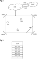
- a spherical coordinate system is a coordinate system for three-dimensional space where the position of a point is specified by three numbers: the radial distance r of that point from a fixed origin, its polar angle ⁇ measured from a fixed zenith direction, and the azimuthal angle ⁇ of its orthogonal projection on a reference plane that passes through the origin and is orthogonal to the zenith, measured from a fixed reference direction on that plane.
- the spherical coordinates vary at the following range: r ⁇ 0 0 ⁇ ⁇ ⁇ ⁇ 0 ⁇ ⁇ ⁇ 2 ⁇ or ⁇ ⁇ ⁇ ⁇ ⁇ ⁇ ⁇
- locator device ANC4 is shown that measures a direction between itself and the mobile device TG1. That direction is a location indicator as used in this disclosure.
- such a locator device after the appropriate coordinate transformations, provides two angles ⁇ and ⁇ which are the spherical coordinates of the target, except of the "r". These two angles are measured with respect to global coordinate axes that have been transferred to the position of the locator device without changing its orientation.
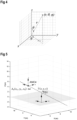
- Directional vector ⁇ i ideally defines completely a 3D straight line which contains the locator device ANC4 and the mobile device TG1, provided that no error has occurred.
- the actual ground truth position of the mobile device TG1 may deviate from the estimated X ⁇ output of the mobile device TG1 if one or more of the location indicators are inaccurate. While some inaccuracies may not be prevented, faulty measurements and therefore faulty location indicators may severely influence the estimated position.
- the deviation from the actual position can be determined for each location indicator.
- the dashed line indicating the directional vector ⁇ indicates where the mobile device TG1 would be, if the location indicator was fully correct.
- the dashed line resembles a locus of the directional vector, i.e. possible positions in view of the location indicator.
- Such loci can also be shown for the other locator devices of the positioning system.
- locator device ANC3 If we look carefully at the example room with the five locator devices ANC1 to ANC5, we will observe that with respect to the estimated position, called a draft estimation in Figures 6A and 6B , of the mobile device TG1, the straight line locus, which is defined by locator device ANC3, behaves as an outlier. Although locator device ANC3 with the corresponding line locus may have its own contribution on the determination of the estimated position, together with the other locator devices, it nevertheless can be seen that the locus of locator device ANC3 has a large distance from the estimated position of the mobile device TG1, which is determined using a LS solution based on all the loci. Therefore locator device ANC3 is suspicious for being an outlier.
- a distance between the estimated position of the mobile device TG1 and the line locus of locator device ANC3 can be determined with known methods of linear algebra.
- the resulting distance value can be used to determine the confidence indicator. For example, if the distance value and/or the resulting confidence indicator exceeds a threshold value, the anomaly indicator may be generated and stored in the anomaly cache for locator device ANC3.
- the confidence criterion in such case may be a threshold distance or derived from such threshold distance, for example.
- the distance value determined this way may also be used to determine a weight factor for this locator device. For example, higher distance values lead to a lower weight factor for the corresponding locator device, respectively locus.
- the LS algorithm of equation (6) may be extended to a weighted LS, WLS, algorithm for refining the estimated position. Further details on such weight factors, loci, distances to loci and their application in a WLS algorithm can be found in u-blox application EP 21197751.7, filed on September 20, 2021 .
- the improved processing concept may come into effect if one or more locator devices are misaligned, actively or by mistake, or are overloaded by rogue tags or other mobile devices. Also in a situation where a locator device is hacked and starts sending fake data, the improved processing concept may detect this situation and generate the corresponding alert message. The same applies if the locator device is dead and/or bricked because of repeated crashes or the like. For example, as shown in Figure 2 , a temporary obstacle can block the antenna of the locator device, e.g. leading to a decrease of the signal quality and/or accuracy.
- Various embodiments of the improved processing concept can be implemented in the form of logic in software or hardware or a combination of both.
- the logic may be stored in a computer readable or machine-readable storage medium as a set of instructions adapted to direct one or more processors of a (distributed) computer system to perform a set of steps disclosed in embodiments of the improved processing concept.
- the logic may form part of a computer program product adapted to direct an information-processing device to automatically perform a set of steps disclosed in embodiments of the improved processing concept.
Landscapes
- Engineering & Computer Science (AREA)
- Physics & Mathematics (AREA)
- General Physics & Mathematics (AREA)
- Radar, Positioning & Navigation (AREA)
- Remote Sensing (AREA)
- Computer Networks & Wireless Communication (AREA)
- Signal Processing (AREA)
- Position Fixing By Use Of Radio Waves (AREA)
Claims (15)
- Verfahren zum Erkennen von Anomalien in einem Positionierungssystem, wobei das Verfahren umfasst- Empfangen (101), für eine Vielzahl von Ortungsvorrichtungen (ANC1, ANC2, ANC3, ANC4), von jeweiligen Standortindikatoren, die mindestens einem Mobilgerät (TG1, TG2, TG3) zugeordnet sind;- Bestimmen (102) einer Position des mindestens einen Mobilgeräts (TG1, TG2, TG3) auf der Grundlage der empfangenen Standortindikatoren;- Erfassen (103), für mindestens einen der empfangenen Standortindikatoren, eines Vertrauensindikators, der dem mindestens einen der Standortindikatoren zugeordnet ist;- Bestimmen (104) für jeden erfassten Vertrauensindikator, ob ein Vertrauenskriterium erfüllt ist, und Speichern eines Anomalie-Indikators in einem Anomalie-Cache (CCH), wenn das Vertrauenskriterium nicht erfüllt ist, wobei jeder Anomalie-Indikator der Ortungsvorrichtung zugeordnet ist, für die der Standortindikator empfangen wird; und- Erzeugen (105) einer Anomalie-Warnmeldung für mindestens eine der Ortungsvorrichtungen auf der Grundlage einer Auswertung der Anomalie-Indikatoren, die für die mindestens eine der Ortungsvorrichtungen gespeichert sind.
- Verfahren nach Anspruch 1, wobei jeder Standortindikator eines der folgenden Elemente enthält:- eine Richtung zwischen der jeweiligen Ortungsvorrichtung (ANC1, ANC2, ANC3, ANC4) und dem Mobilgerät (TG1, TG2, TG3) ;- eine Entfernung zwischen der jeweiligen Ortungsvorrichtung (ANC1, ANC2, ANC3, ANC4) und dem Mobilgerät (TG1, TG2, TG3) ;- eine Richtung und ein Abstand zwischen der jeweiligen Ortungsvorrichtung (ANC1, ANC2, ANC3, ANC4) und dem Mobilgerät (TG1, TG2, TG3).
- Verfahren nach Anspruch 1 oder 2, wobei das Erfassen des Vertrauensindikators umfasst- Definieren eines Lokus, der auf dem mindestens einen der Standortindikatoren basiert, wobei der Lokus dem mindestens einen Mobilgerät (TG1, TG2, TG3) zugeordnet ist;- Bestimmen eines Abstandswertes zwischen der bestimmten Position des mindestens einen Mobilgeräts und dem Lokus; und- Bestimmen des Vertrauensindikators auf der Grundlage des bestimmten Abstandswertes.
- Verfahren nach einem der Ansprüche 1 bis 3, wobei das Erfassen des Vertrauensindikators umfasst- Bestimmen eines weiteren Abstandswertes zwischen der bestimmten Position des mindestens einen Mobilgeräts und einer bekannten Position der Ortungsvorrichtung, für die der mindestens eine der Standortindikatoren empfangen wird; und- Bestimmen des Vertrauensindikators auf der Grundlage des bestimmten weiteren Abstandswertes.
- Verfahren nach einem der Ansprüche 1 bis 4, wobei das Erfassen des Vertrauensindikators umfasst- Empfangen oder Bestimmen eines Gewichtungsfaktors, der dem mindestens einen der Standortindikatoren und/oder der Ortungsvorrichtung, für die der mindestens eine der Standortindikatoren empfangen wird, zugeordnet ist; und- Bestimmen des Vertrauensindikators auf der Grundlage des Gewichtungsfaktors; und- Bestimmen der Position des mindestens einen Mobilgeräts (TG1, TG2, TG3) basierend auf den empfangenen Standortindikatoren und dem Gewichtungsfaktor.
- Verfahren nach einem der Ansprüche 1 bis 5, wobei das Erfassen des Vertrauensindikators umfasst- Empfangen von Qualitätsinformationen, die dem mindestens einen der Standortindikatoren zugeordnet sind, wobei die Qualitätsinformationen mindestens eines der folgenden Merkmale umfassen:- eine Signalstärke, die dem mindestens einen der Standortindikatoren zugeordnet ist;- eine Anzahl von Antennenelementen der Ortungsvorrichtung, für die der mindestens eine der Standortindikatoren empfangen wird;- einen Rauschwert, insbesondere ein Signal-RauschVerhältnis, der dem mindestens einen der Standortindikatoren zugeordnet ist;- einen Qualitätswert einer Referenzperiode einer Sinuswelle, die dem mindestens einen der Standortindikatoren zugeordnet ist; und- Bestimmen des Vertrauensindikators auf der Grundlage der empfangenen Qualitätsinformationen.
- Verfahren nach einem der Ansprüche 1 bis 6, wobei jeder Anomalie-Indikator ferner dem Mobilgerät zugeordnet ist, dem der Vertrauensindikator über den entsprechenden Standortindikator zugeordnet ist.
- Verfahren nach einem der Ansprüche 1 bis 7, wobei das Erzeugen der Anomalie-Warnmeldung ferner auf einer Auswertung der Anomalie-Indikatoren basiert, die für die mindestens eine der Ortungsvorrichtungen innerhalb eines vordefinierten Zeitraums gespeichert sind.
- Verfahren nach einem der Ansprüche 1 bis 8, wobei die Auswertung der Anomalie-Indikatoren auf mindestens einem der folgenden basiert:- einer Anzahl der Anomalie-Indikatoren, die für die mindestens eine der Ortungsvorrichtungen gespeichert sind;- einer Ausgabe eines trainierten Algorithmus für maschinelles Lernen, der die gespeicherten Anomalie-Indikatoren und/oder die mit den gespeicherten Anomalie-Indikatoren verbundenen Vertrauensindikatoren verarbeitet.
- Eine Positionsbestimmungsvorrichtung (LPE) für ein Positionsbestimmungssystem, wobei die Positionsbestimmungsvorrichtung (LPE) eingerichtet ist zum:- Empfangen, für eine Vielzahl von Ortungsvorrichtungen (ANC1, ANC2, ANC3, ANC4), von jeweiligen Standortindikatoren, die mindestens einem Mobilgerät (TG1, TG2, TG3) zugeordnet sind;- Bestimmen einer Position des mindestens einen Mobilgeräts (TG1, TG2, TG3) basierend auf den empfangenen Standortindikatoren;- Erfassen, für mindestens einen der empfangenen Standortindikatoren, eines Vertrauensindikators, der dem mindestens einen der Standortindikatoren zugeordnet ist;- Bestimmen, für jeden erfassten Vertrauensindikator, ob ein Vertrauenskriterium erfüllt ist, und Speichern eines Anomalie-Indikators in einem Anomalie-Cache, wenn das Vertrauenskriterium nicht erfüllt ist, wobei jeder Anomalie-Indikator der Ortungsvorrichtung zugeordnet ist, für die der Standortindikator empfangen wird; und- Erzeugen einer Anomalie-Warnmeldung für mindestens eine der Ortungsvorrichtungen auf der Grundlage einer Auswertung der Anomalie-Indikatoren, die für die mindestens eine der Ortungsvorrichtungen gespeichert sind.
- Positionsbestimmungsvorrichtung (LPE) nach Anspruch 10, wobei die Positionsbestimmungsvorrichtung (LPE) zum Erfassen des Vertrauensindikators ferner eingerichtet ist zum- Definieren eines Lokus, der auf dem mindestens einen der Standortindikatoren basiert, wobei der Lokus dem mindestens einen Mobilgerät (TG1, TG2, TG3) zugeordnet ist;- Bestimmen eines Abstandswertes zwischen der bestimmten Position des mindestens einen Mobilgeräts und dem Lokus; und- Bestimmen des Vertrauensindikators auf der Grundlage des bestimmten Abstandswertes.
- Positionsbestimmungsvorrichtung (LPE) nach Anspruch 10 oder 11, wobei die Positionsbestimmungsvorrichtung (LPE) zum Erfassen des Vertrauensindikators ferner eingerichtet ist zum- Empfangen von Qualitätsinformationen, die dem mindestens einen der Standortindikatoren zugeordnet sind, wobei die Qualitätsinformationen mindestens eines der folgenden Merkmale umfassen:- eine Signalstärke, die dem mindestens einen der Standortindikatoren zugeordnet ist;- eine Anzahl von Antennenelementen der Ortungsvorrichtung, für die der mindestens eine der Standortindikatoren empfangen wird;- einen Rauschwert, insbesondere ein Signal-RauschVerhältnis, der dem mindestens einen der Standortindikatoren zugeordnet ist;- einen Qualitätswert einer Referenzperiode einer Sinuswelle, die dem mindestens einen der Standortindikatoren zugeordnet ist; und- Bestimmen des Vertrauensindikators auf der Grundlage der empfangenen Qualitätsinformationen.
- Positionsbestimmungsvorrichtung (LPE) nach einem der Ansprüche 10 bis 12, wobei die Positionsbestimmungsvorrichtung (LPE) ferner eingerichtet ist, die Anomalie-Warnmeldung auf der Grundlage einer Auswertung der Anomalie-Indikatoren zu erzeugen, die für die mindestens eine der Ortungsvorrichtungen innerhalb einer vordefinierten Zeitspanne gespeichert sind.
- Computerprogrammprodukt, das Anweisungen enthält, die, wenn sie auf einem Prozessor ausgeführt werden, den Prozessor veranlassen, das Verfahren nach einem der Ansprüche 1 bis 9 durchzuführen.
- Computerlesbares Speichermedium, das das Computerprogrammprodukt nach Anspruch 14 enthält.
Priority Applications (3)
| Application Number | Priority Date | Filing Date | Title |
|---|---|---|---|
| EP21212030.7A EP4191271B1 (de) | 2021-12-02 | 2021-12-02 | Verfahren zur erkennung von anomalien in einem positionierungssystem und positionierungsmaschine für ein positionierungssystem |
| US17/988,108 US12386013B2 (en) | 2021-12-02 | 2022-11-16 | Method for detecting anomalies in a positioning system and positioning engine for a positioning system |
| CN202211541087.4A CN116233899A (zh) | 2021-12-02 | 2022-12-02 | 用于检测定位系统中的异常的方法和定位系统的定位引擎 |
Applications Claiming Priority (1)
| Application Number | Priority Date | Filing Date | Title |
|---|---|---|---|
| EP21212030.7A EP4191271B1 (de) | 2021-12-02 | 2021-12-02 | Verfahren zur erkennung von anomalien in einem positionierungssystem und positionierungsmaschine für ein positionierungssystem |
Publications (2)
| Publication Number | Publication Date |
|---|---|
| EP4191271A1 EP4191271A1 (de) | 2023-06-07 |
| EP4191271B1 true EP4191271B1 (de) | 2024-05-22 |
Family
ID=78821599
Family Applications (1)
| Application Number | Title | Priority Date | Filing Date |
|---|---|---|---|
| EP21212030.7A Active EP4191271B1 (de) | 2021-12-02 | 2021-12-02 | Verfahren zur erkennung von anomalien in einem positionierungssystem und positionierungsmaschine für ein positionierungssystem |
Country Status (3)
| Country | Link |
|---|---|
| US (1) | US12386013B2 (de) |
| EP (1) | EP4191271B1 (de) |
| CN (1) | CN116233899A (de) |
Cited By (1)
| Publication number | Priority date | Publication date | Assignee | Title |
|---|---|---|---|---|
| US20230388153A1 (en) * | 2022-05-25 | 2023-11-30 | U-Blox Ag | Method for providing at least one estimated parameter of a wireless communication channel and radio receiver device |
Families Citing this family (1)
| Publication number | Priority date | Publication date | Assignee | Title |
|---|---|---|---|---|
| CN121122027B (zh) * | 2025-11-14 | 2026-02-13 | 浙江大华技术股份有限公司 | 设备位置异常的校正方法以及存储介质 |
Family Cites Families (6)
| Publication number | Priority date | Publication date | Assignee | Title |
|---|---|---|---|---|
| KR101713035B1 (ko) * | 2013-05-26 | 2017-03-07 | 인텔 아이피 코포레이션 | 모바일 디바이스의 위치를 추정하는 장치, 시스템 및 방법 |
| EP3092830B2 (de) * | 2014-01-10 | 2020-02-19 | Signify Holding B.V. | Rückkoppelung in einem positionierungssystem |
| JP6477363B2 (ja) * | 2015-08-27 | 2019-03-06 | 横河電機株式会社 | 位置情報オーサリングシステム、位置情報オーサリング装置、および位置情報オーサリング方法 |
| US20230236283A1 (en) * | 2020-04-14 | 2023-07-27 | Pozyx N.V. | Improved Method and System for Positioning |
| CN111852456B (zh) * | 2020-07-29 | 2023-04-07 | 中国矿业大学 | 基于因子图的鲁棒uwb井下锚杆钻孔定位方法 |
| EP4378232A4 (de) * | 2021-07-27 | 2025-04-16 | Telefonaktiebolaget LM Ericsson (publ) | Netzwerkknoten, benutzergerät und verfahren zur bestimmung der zuverlässigkeit von positionen eines benutzergeräts |
-
2021
- 2021-12-02 EP EP21212030.7A patent/EP4191271B1/de active Active
-
2022
- 2022-11-16 US US17/988,108 patent/US12386013B2/en active Active
- 2022-12-02 CN CN202211541087.4A patent/CN116233899A/zh active Pending
Cited By (2)
| Publication number | Priority date | Publication date | Assignee | Title |
|---|---|---|---|---|
| US20230388153A1 (en) * | 2022-05-25 | 2023-11-30 | U-Blox Ag | Method for providing at least one estimated parameter of a wireless communication channel and radio receiver device |
| US12328205B2 (en) * | 2022-05-25 | 2025-06-10 | U-Blox Ag | Method for providing at least one estimated parameter of a wireless communication channel and radio receiver device |
Also Published As
| Publication number | Publication date |
|---|---|
| EP4191271A1 (de) | 2023-06-07 |
| US12386013B2 (en) | 2025-08-12 |
| CN116233899A (zh) | 2023-06-06 |
| US20230176167A1 (en) | 2023-06-08 |
Similar Documents
| Publication | Publication Date | Title |
|---|---|---|
| US20230384462A1 (en) | System and method for tracking and forecasting the positions of marine vessels | |
| US12080060B2 (en) | Method and system for indoor multipath ghosts recognition | |
| US10175348B2 (en) | Use of range-rate measurements in a fusion tracking system via projections | |
| EP2769233B1 (de) | Drahtloses positionierungssystem auf ankunftszeitbasis | |
| US12386013B2 (en) | Method for detecting anomalies in a positioning system and positioning engine for a positioning system | |
| US9660740B2 (en) | Signal strength distribution establishing method and wireless positioning system | |
| US20160139238A1 (en) | System and method for rfid indoor localization | |
| US20070164897A1 (en) | Single scan track initiation for radars having rotating, electronically scanned antennas | |
| Garip et al. | Interloc: An interference-aware rssi-based localization and sybil attack detection mechanism for vehicular ad hoc networks | |
| CN106454747B (zh) | 手机终端的无线定位方法 | |
| JP2010038895A (ja) | 測位システム、測位方法及び測位プログラム | |
| EP1532464A1 (de) | Fehlerabschützung bezüglich des orts einer zieleinrichtung, betreibbar zur bewegung in einer drahtlosen umgebung | |
| JP2008510138A (ja) | スプーフィングによる信号の矛盾の検出器 | |
| AU2016264465A1 (en) | Method, system, and computer program product for GNSS receiver signal health and security analysis | |
| Almaaitah et al. | 3D passive tag localization schemes for indoor RFID applications | |
| Swaszek et al. | Using range information to detect spoofing in platoons of vehicles | |
| US12429549B2 (en) | Cooperative positioning method and apparatus | |
| EP4152039B1 (de) | Verfahren und positionierungs-engine zur bestimmung einer position einer mobilen vorrichtung | |
| US20200033439A1 (en) | Multi-algorithm trilateration system | |
| EP2887748B1 (de) | Verfahren zur bestimmung der positionen mobiler empfängereinheiten in geschlossenen räumen | |
| EP4386423A1 (de) | Positionierungsverfahren, positionierungsvorrichtung und system | |
| Zhang et al. | Multi-static sonar distributed quantized detection fusion method based on NP criterion | |
| US20060221864A1 (en) | Method and apparatus for determining a best technique to use when locating a node | |
| CN118741612B (zh) | 临近空间平台的移动消息安全验证方法及装置 | |
| CN112770260B (zh) | 基于地理围栏的定位方法及装置、定位终端及存储介质 |
Legal Events
| Date | Code | Title | Description |
|---|---|---|---|
| PUAI | Public reference made under article 153(3) epc to a published international application that has entered the european phase |
Free format text: ORIGINAL CODE: 0009012 |
|
| STAA | Information on the status of an ep patent application or granted ep patent |
Free format text: STATUS: THE APPLICATION HAS BEEN PUBLISHED |
|
| AK | Designated contracting states |
Kind code of ref document: A1 Designated state(s): AL AT BE BG CH CY CZ DE DK EE ES FI FR GB GR HR HU IE IS IT LI LT LU LV MC MK MT NL NO PL PT RO RS SE SI SK SM TR |
|
| STAA | Information on the status of an ep patent application or granted ep patent |
Free format text: STATUS: REQUEST FOR EXAMINATION WAS MADE |
|
| 17P | Request for examination filed |
Effective date: 20231024 |
|
| RBV | Designated contracting states (corrected) |
Designated state(s): AL AT BE BG CH CY CZ DE DK EE ES FI FR GB GR HR HU IE IS IT LI LT LU LV MC MK MT NL NO PL PT RO RS SE SI SK SM TR |
|
| GRAP | Despatch of communication of intention to grant a patent |
Free format text: ORIGINAL CODE: EPIDOSNIGR1 |
|
| STAA | Information on the status of an ep patent application or granted ep patent |
Free format text: STATUS: GRANT OF PATENT IS INTENDED |
|
| INTG | Intention to grant announced |
Effective date: 20240111 |
|
| GRAS | Grant fee paid |
Free format text: ORIGINAL CODE: EPIDOSNIGR3 |
|
| GRAA | (expected) grant |
Free format text: ORIGINAL CODE: 0009210 |
|
| STAA | Information on the status of an ep patent application or granted ep patent |
Free format text: STATUS: THE PATENT HAS BEEN GRANTED |
|
| AK | Designated contracting states |
Kind code of ref document: B1 Designated state(s): AL AT BE BG CH CY CZ DE DK EE ES FI FR GB GR HR HU IE IS IT LI LT LU LV MC MK MT NL NO PL PT RO RS SE SI SK SM TR |
|
| REG | Reference to a national code |
Ref country code: GB Ref legal event code: FG4D |
|
| REG | Reference to a national code |
Ref country code: CH Ref legal event code: EP |
|
| REG | Reference to a national code |
Ref country code: DE Ref legal event code: R096 Ref document number: 602021013537 Country of ref document: DE |
|
| REG | Reference to a national code |
Ref country code: IE Ref legal event code: FG4D |
|
| REG | Reference to a national code |
Ref country code: LT Ref legal event code: MG9D |
|
| REG | Reference to a national code |
Ref country code: NL Ref legal event code: MP Effective date: 20240522 |
|
| PG25 | Lapsed in a contracting state [announced via postgrant information from national office to epo] |
Ref country code: IS Free format text: LAPSE BECAUSE OF FAILURE TO SUBMIT A TRANSLATION OF THE DESCRIPTION OR TO PAY THE FEE WITHIN THE PRESCRIBED TIME-LIMIT Effective date: 20240922 |
|
| PG25 | Lapsed in a contracting state [announced via postgrant information from national office to epo] |
Ref country code: BG Free format text: LAPSE BECAUSE OF FAILURE TO SUBMIT A TRANSLATION OF THE DESCRIPTION OR TO PAY THE FEE WITHIN THE PRESCRIBED TIME-LIMIT Effective date: 20240522 |
|
| PG25 | Lapsed in a contracting state [announced via postgrant information from national office to epo] |
Ref country code: HR Free format text: LAPSE BECAUSE OF FAILURE TO SUBMIT A TRANSLATION OF THE DESCRIPTION OR TO PAY THE FEE WITHIN THE PRESCRIBED TIME-LIMIT Effective date: 20240522 Ref country code: FI Free format text: LAPSE BECAUSE OF FAILURE TO SUBMIT A TRANSLATION OF THE DESCRIPTION OR TO PAY THE FEE WITHIN THE PRESCRIBED TIME-LIMIT Effective date: 20240522 |
|
| PG25 | Lapsed in a contracting state [announced via postgrant information from national office to epo] |
Ref country code: GR Free format text: LAPSE BECAUSE OF FAILURE TO SUBMIT A TRANSLATION OF THE DESCRIPTION OR TO PAY THE FEE WITHIN THE PRESCRIBED TIME-LIMIT Effective date: 20240823 |
|
| PG25 | Lapsed in a contracting state [announced via postgrant information from national office to epo] |
Ref country code: PT Free format text: LAPSE BECAUSE OF FAILURE TO SUBMIT A TRANSLATION OF THE DESCRIPTION OR TO PAY THE FEE WITHIN THE PRESCRIBED TIME-LIMIT Effective date: 20240923 |
|
| REG | Reference to a national code |
Ref country code: AT Ref legal event code: MK05 Ref document number: 1689198 Country of ref document: AT Kind code of ref document: T Effective date: 20240522 |
|
| PG25 | Lapsed in a contracting state [announced via postgrant information from national office to epo] |
Ref country code: NL Free format text: LAPSE BECAUSE OF FAILURE TO SUBMIT A TRANSLATION OF THE DESCRIPTION OR TO PAY THE FEE WITHIN THE PRESCRIBED TIME-LIMIT Effective date: 20240522 |
|
| PG25 | Lapsed in a contracting state [announced via postgrant information from national office to epo] |
Ref country code: ES Free format text: LAPSE BECAUSE OF FAILURE TO SUBMIT A TRANSLATION OF THE DESCRIPTION OR TO PAY THE FEE WITHIN THE PRESCRIBED TIME-LIMIT Effective date: 20240522 |
|
| PG25 | Lapsed in a contracting state [announced via postgrant information from national office to epo] |
Ref country code: AT Free format text: LAPSE BECAUSE OF FAILURE TO SUBMIT A TRANSLATION OF THE DESCRIPTION OR TO PAY THE FEE WITHIN THE PRESCRIBED TIME-LIMIT Effective date: 20240522 |
|
| PG25 | Lapsed in a contracting state [announced via postgrant information from national office to epo] |
Ref country code: PL Free format text: LAPSE BECAUSE OF FAILURE TO SUBMIT A TRANSLATION OF THE DESCRIPTION OR TO PAY THE FEE WITHIN THE PRESCRIBED TIME-LIMIT Effective date: 20240522 |
|
| PG25 | Lapsed in a contracting state [announced via postgrant information from national office to epo] |
Ref country code: LV Free format text: LAPSE BECAUSE OF FAILURE TO SUBMIT A TRANSLATION OF THE DESCRIPTION OR TO PAY THE FEE WITHIN THE PRESCRIBED TIME-LIMIT Effective date: 20240522 |
|
| PG25 | Lapsed in a contracting state [announced via postgrant information from national office to epo] |
Ref country code: PT Free format text: LAPSE BECAUSE OF FAILURE TO SUBMIT A TRANSLATION OF THE DESCRIPTION OR TO PAY THE FEE WITHIN THE PRESCRIBED TIME-LIMIT Effective date: 20240923 Ref country code: PL Free format text: LAPSE BECAUSE OF FAILURE TO SUBMIT A TRANSLATION OF THE DESCRIPTION OR TO PAY THE FEE WITHIN THE PRESCRIBED TIME-LIMIT Effective date: 20240522 Ref country code: NO Free format text: LAPSE BECAUSE OF FAILURE TO SUBMIT A TRANSLATION OF THE DESCRIPTION OR TO PAY THE FEE WITHIN THE PRESCRIBED TIME-LIMIT Effective date: 20240822 Ref country code: NL Free format text: LAPSE BECAUSE OF FAILURE TO SUBMIT A TRANSLATION OF THE DESCRIPTION OR TO PAY THE FEE WITHIN THE PRESCRIBED TIME-LIMIT Effective date: 20240522 Ref country code: LV Free format text: LAPSE BECAUSE OF FAILURE TO SUBMIT A TRANSLATION OF THE DESCRIPTION OR TO PAY THE FEE WITHIN THE PRESCRIBED TIME-LIMIT Effective date: 20240522 Ref country code: IS Free format text: LAPSE BECAUSE OF FAILURE TO SUBMIT A TRANSLATION OF THE DESCRIPTION OR TO PAY THE FEE WITHIN THE PRESCRIBED TIME-LIMIT Effective date: 20240922 Ref country code: HR Free format text: LAPSE BECAUSE OF FAILURE TO SUBMIT A TRANSLATION OF THE DESCRIPTION OR TO PAY THE FEE WITHIN THE PRESCRIBED TIME-LIMIT Effective date: 20240522 Ref country code: GR Free format text: LAPSE BECAUSE OF FAILURE TO SUBMIT A TRANSLATION OF THE DESCRIPTION OR TO PAY THE FEE WITHIN THE PRESCRIBED TIME-LIMIT Effective date: 20240823 Ref country code: FI Free format text: LAPSE BECAUSE OF FAILURE TO SUBMIT A TRANSLATION OF THE DESCRIPTION OR TO PAY THE FEE WITHIN THE PRESCRIBED TIME-LIMIT Effective date: 20240522 Ref country code: ES Free format text: LAPSE BECAUSE OF FAILURE TO SUBMIT A TRANSLATION OF THE DESCRIPTION OR TO PAY THE FEE WITHIN THE PRESCRIBED TIME-LIMIT Effective date: 20240522 Ref country code: BG Free format text: LAPSE BECAUSE OF FAILURE TO SUBMIT A TRANSLATION OF THE DESCRIPTION OR TO PAY THE FEE WITHIN THE PRESCRIBED TIME-LIMIT Effective date: 20240522 Ref country code: AT Free format text: LAPSE BECAUSE OF FAILURE TO SUBMIT A TRANSLATION OF THE DESCRIPTION OR TO PAY THE FEE WITHIN THE PRESCRIBED TIME-LIMIT Effective date: 20240522 Ref country code: RS Free format text: LAPSE BECAUSE OF FAILURE TO SUBMIT A TRANSLATION OF THE DESCRIPTION OR TO PAY THE FEE WITHIN THE PRESCRIBED TIME-LIMIT Effective date: 20240822 |
|
| PG25 | Lapsed in a contracting state [announced via postgrant information from national office to epo] |
Ref country code: DK Free format text: LAPSE BECAUSE OF FAILURE TO SUBMIT A TRANSLATION OF THE DESCRIPTION OR TO PAY THE FEE WITHIN THE PRESCRIBED TIME-LIMIT Effective date: 20240522 |
|
| PG25 | Lapsed in a contracting state [announced via postgrant information from national office to epo] |
Ref country code: EE Free format text: LAPSE BECAUSE OF FAILURE TO SUBMIT A TRANSLATION OF THE DESCRIPTION OR TO PAY THE FEE WITHIN THE PRESCRIBED TIME-LIMIT Effective date: 20240522 |
|
| PG25 | Lapsed in a contracting state [announced via postgrant information from national office to epo] |
Ref country code: CZ Free format text: LAPSE BECAUSE OF FAILURE TO SUBMIT A TRANSLATION OF THE DESCRIPTION OR TO PAY THE FEE WITHIN THE PRESCRIBED TIME-LIMIT Effective date: 20240522 |
|
| PG25 | Lapsed in a contracting state [announced via postgrant information from national office to epo] |
Ref country code: RO Free format text: LAPSE BECAUSE OF FAILURE TO SUBMIT A TRANSLATION OF THE DESCRIPTION OR TO PAY THE FEE WITHIN THE PRESCRIBED TIME-LIMIT Effective date: 20240522 Ref country code: SK Free format text: LAPSE BECAUSE OF FAILURE TO SUBMIT A TRANSLATION OF THE DESCRIPTION OR TO PAY THE FEE WITHIN THE PRESCRIBED TIME-LIMIT Effective date: 20240522 |
|
| PG25 | Lapsed in a contracting state [announced via postgrant information from national office to epo] |
Ref country code: SK Free format text: LAPSE BECAUSE OF FAILURE TO SUBMIT A TRANSLATION OF THE DESCRIPTION OR TO PAY THE FEE WITHIN THE PRESCRIBED TIME-LIMIT Effective date: 20240522 Ref country code: RO Free format text: LAPSE BECAUSE OF FAILURE TO SUBMIT A TRANSLATION OF THE DESCRIPTION OR TO PAY THE FEE WITHIN THE PRESCRIBED TIME-LIMIT Effective date: 20240522 Ref country code: EE Free format text: LAPSE BECAUSE OF FAILURE TO SUBMIT A TRANSLATION OF THE DESCRIPTION OR TO PAY THE FEE WITHIN THE PRESCRIBED TIME-LIMIT Effective date: 20240522 Ref country code: DK Free format text: LAPSE BECAUSE OF FAILURE TO SUBMIT A TRANSLATION OF THE DESCRIPTION OR TO PAY THE FEE WITHIN THE PRESCRIBED TIME-LIMIT Effective date: 20240522 Ref country code: CZ Free format text: LAPSE BECAUSE OF FAILURE TO SUBMIT A TRANSLATION OF THE DESCRIPTION OR TO PAY THE FEE WITHIN THE PRESCRIBED TIME-LIMIT Effective date: 20240522 |
|
| PG25 | Lapsed in a contracting state [announced via postgrant information from national office to epo] |
Ref country code: IT Free format text: LAPSE BECAUSE OF FAILURE TO SUBMIT A TRANSLATION OF THE DESCRIPTION OR TO PAY THE FEE WITHIN THE PRESCRIBED TIME-LIMIT Effective date: 20240522 |
|
| REG | Reference to a national code |
Ref country code: DE Ref legal event code: R097 Ref document number: 602021013537 Country of ref document: DE |
|
| PLBE | No opposition filed within time limit |
Free format text: ORIGINAL CODE: 0009261 |
|
| STAA | Information on the status of an ep patent application or granted ep patent |
Free format text: STATUS: NO OPPOSITION FILED WITHIN TIME LIMIT |
|
| PG25 | Lapsed in a contracting state [announced via postgrant information from national office to epo] |
Ref country code: SI Free format text: LAPSE BECAUSE OF FAILURE TO SUBMIT A TRANSLATION OF THE DESCRIPTION OR TO PAY THE FEE WITHIN THE PRESCRIBED TIME-LIMIT Effective date: 20240522 |
|
| 26N | No opposition filed |
Effective date: 20250225 |
|
| PG25 | Lapsed in a contracting state [announced via postgrant information from national office to epo] |
Ref country code: MC Free format text: LAPSE BECAUSE OF FAILURE TO SUBMIT A TRANSLATION OF THE DESCRIPTION OR TO PAY THE FEE WITHIN THE PRESCRIBED TIME-LIMIT Effective date: 20240522 |
|
| REG | Reference to a national code |
Ref country code: CH Ref legal event code: PL |
|
| PG25 | Lapsed in a contracting state [announced via postgrant information from national office to epo] |
Ref country code: LU Free format text: LAPSE BECAUSE OF NON-PAYMENT OF DUE FEES Effective date: 20241202 |
|
| PG25 | Lapsed in a contracting state [announced via postgrant information from national office to epo] |
Ref country code: SE Free format text: LAPSE BECAUSE OF FAILURE TO SUBMIT A TRANSLATION OF THE DESCRIPTION OR TO PAY THE FEE WITHIN THE PRESCRIBED TIME-LIMIT Effective date: 20240522 |
|
| REG | Reference to a national code |
Ref country code: BE Ref legal event code: MM Effective date: 20241231 |
|
| PG25 | Lapsed in a contracting state [announced via postgrant information from national office to epo] |
Ref country code: BE Free format text: LAPSE BECAUSE OF NON-PAYMENT OF DUE FEES Effective date: 20241231 |
|
| PG25 | Lapsed in a contracting state [announced via postgrant information from national office to epo] |
Ref country code: CH Free format text: LAPSE BECAUSE OF NON-PAYMENT OF DUE FEES Effective date: 20241231 |
|
| PG25 | Lapsed in a contracting state [announced via postgrant information from national office to epo] |
Ref country code: IE Free format text: LAPSE BECAUSE OF NON-PAYMENT OF DUE FEES Effective date: 20241202 |
|
| PGFP | Annual fee paid to national office [announced via postgrant information from national office to epo] |
Ref country code: DE Payment date: 20251211 Year of fee payment: 5 |
|
| PGFP | Annual fee paid to national office [announced via postgrant information from national office to epo] |
Ref country code: GB Payment date: 20251219 Year of fee payment: 5 |
|
| PGFP | Annual fee paid to national office [announced via postgrant information from national office to epo] |
Ref country code: FR Payment date: 20251229 Year of fee payment: 5 |