EP4191127A1 - Beleuchtungsvorrichtung für motorradscheinwerfer - Google Patents
Beleuchtungsvorrichtung für motorradscheinwerfer Download PDFInfo
- Publication number
- EP4191127A1 EP4191127A1 EP21211988.7A EP21211988A EP4191127A1 EP 4191127 A1 EP4191127 A1 EP 4191127A1 EP 21211988 A EP21211988 A EP 21211988A EP 4191127 A1 EP4191127 A1 EP 4191127A1
- Authority
- EP
- European Patent Office
- Prior art keywords
- light
- light guide
- illumination device
- guide elements
- segmented
- Prior art date
- Legal status (The legal status is an assumption and is not a legal conclusion. Google has not performed a legal analysis and makes no representation as to the accuracy of the status listed.)
- Pending
Links
- 238000005286 illumination Methods 0.000 title claims abstract description 65
- 238000000265 homogenisation Methods 0.000 claims abstract description 37
- 238000009826 distribution Methods 0.000 claims description 26
- 230000004913 activation Effects 0.000 claims description 7
- 230000001678 irradiating effect Effects 0.000 claims description 7
- 230000003287 optical effect Effects 0.000 claims description 4
- 230000009849 deactivation Effects 0.000 claims description 3
- 230000007423 decrease Effects 0.000 claims description 3
- 238000001746 injection moulding Methods 0.000 claims description 3
- 238000000465 moulding Methods 0.000 claims description 3
- 230000011218 segmentation Effects 0.000 claims description 3
- 102100034527 AP-1 complex subunit gamma-like 2 Human genes 0.000 claims description 2
- 101710082919 AP-1 complex subunit gamma-like 2 Proteins 0.000 claims description 2
- 229920001296 polysiloxane Polymers 0.000 description 2
- 230000004075 alteration Effects 0.000 description 1
- 230000000694 effects Effects 0.000 description 1
- 238000002156 mixing Methods 0.000 description 1
- 238000012634 optical imaging Methods 0.000 description 1
- 235000013550 pizza Nutrition 0.000 description 1
- 239000004033 plastic Substances 0.000 description 1
- 229920003023 plastic Polymers 0.000 description 1
- 230000005855 radiation Effects 0.000 description 1
- 230000007704 transition Effects 0.000 description 1
- 239000012780 transparent material Substances 0.000 description 1
Images


Classifications
-
- F—MECHANICAL ENGINEERING; LIGHTING; HEATING; WEAPONS; BLASTING
- F21—LIGHTING
- F21S—NON-PORTABLE LIGHTING DEVICES; SYSTEMS THEREOF; VEHICLE LIGHTING DEVICES SPECIALLY ADAPTED FOR VEHICLE EXTERIORS
- F21S41/00—Illuminating devices specially adapted for vehicle exteriors, e.g. headlamps
- F21S41/10—Illuminating devices specially adapted for vehicle exteriors, e.g. headlamps characterised by the light source
- F21S41/14—Illuminating devices specially adapted for vehicle exteriors, e.g. headlamps characterised by the light source characterised by the type of light source
- F21S41/141—Light emitting diodes [LED]
- F21S41/143—Light emitting diodes [LED] the main emission direction of the LED being parallel to the optical axis of the illuminating device
-
- B—PERFORMING OPERATIONS; TRANSPORTING
- B62—LAND VEHICLES FOR TRAVELLING OTHERWISE THAN ON RAILS
- B62J—CYCLE SADDLES OR SEATS; AUXILIARY DEVICES OR ACCESSORIES SPECIALLY ADAPTED TO CYCLES AND NOT OTHERWISE PROVIDED FOR, e.g. ARTICLE CARRIERS OR CYCLE PROTECTORS
- B62J6/00—Arrangement of optical signalling or lighting devices on cycles; Mounting or supporting thereof; Circuits therefor
- B62J6/02—Headlights
- B62J6/022—Headlights specially adapted for motorcycles or the like
- B62J6/023—Headlights specially adapted for motorcycles or the like responsive to the lean angle of the cycle, e.g. changing intensity or switching sub-lights when cornering
-
- F—MECHANICAL ENGINEERING; LIGHTING; HEATING; WEAPONS; BLASTING
- F21—LIGHTING
- F21S—NON-PORTABLE LIGHTING DEVICES; SYSTEMS THEREOF; VEHICLE LIGHTING DEVICES SPECIALLY ADAPTED FOR VEHICLE EXTERIORS
- F21S41/00—Illuminating devices specially adapted for vehicle exteriors, e.g. headlamps
- F21S41/20—Illuminating devices specially adapted for vehicle exteriors, e.g. headlamps characterised by refractors, transparent cover plates, light guides or filters
- F21S41/25—Projection lenses
- F21S41/265—Composite lenses; Lenses with a patch-like shape
-
- B—PERFORMING OPERATIONS; TRANSPORTING
- B60—VEHICLES IN GENERAL
- B60Q—ARRANGEMENT OF SIGNALLING OR LIGHTING DEVICES, THE MOUNTING OR SUPPORTING THEREOF OR CIRCUITS THEREFOR, FOR VEHICLES IN GENERAL
- B60Q1/00—Arrangement of optical signalling or lighting devices, the mounting or supporting thereof or circuits therefor
- B60Q1/02—Arrangement of optical signalling or lighting devices, the mounting or supporting thereof or circuits therefor the devices being primarily intended to illuminate the way ahead or to illuminate other areas of way or environments
- B60Q1/04—Arrangement of optical signalling or lighting devices, the mounting or supporting thereof or circuits therefor the devices being primarily intended to illuminate the way ahead or to illuminate other areas of way or environments the devices being headlights
- B60Q1/06—Arrangement of optical signalling or lighting devices, the mounting or supporting thereof or circuits therefor the devices being primarily intended to illuminate the way ahead or to illuminate other areas of way or environments the devices being headlights adjustable, e.g. remotely-controlled from inside vehicle
- B60Q1/08—Arrangement of optical signalling or lighting devices, the mounting or supporting thereof or circuits therefor the devices being primarily intended to illuminate the way ahead or to illuminate other areas of way or environments the devices being headlights adjustable, e.g. remotely-controlled from inside vehicle automatically
- B60Q1/12—Arrangement of optical signalling or lighting devices, the mounting or supporting thereof or circuits therefor the devices being primarily intended to illuminate the way ahead or to illuminate other areas of way or environments the devices being headlights adjustable, e.g. remotely-controlled from inside vehicle automatically due to steering position
-
- F—MECHANICAL ENGINEERING; LIGHTING; HEATING; WEAPONS; BLASTING
- F21—LIGHTING
- F21S—NON-PORTABLE LIGHTING DEVICES; SYSTEMS THEREOF; VEHICLE LIGHTING DEVICES SPECIALLY ADAPTED FOR VEHICLE EXTERIORS
- F21S41/00—Illuminating devices specially adapted for vehicle exteriors, e.g. headlamps
- F21S41/10—Illuminating devices specially adapted for vehicle exteriors, e.g. headlamps characterised by the light source
- F21S41/14—Illuminating devices specially adapted for vehicle exteriors, e.g. headlamps characterised by the light source characterised by the type of light source
- F21S41/141—Light emitting diodes [LED]
- F21S41/151—Light emitting diodes [LED] arranged in one or more lines
- F21S41/153—Light emitting diodes [LED] arranged in one or more lines arranged in a matrix
-
- F—MECHANICAL ENGINEERING; LIGHTING; HEATING; WEAPONS; BLASTING
- F21—LIGHTING
- F21S—NON-PORTABLE LIGHTING DEVICES; SYSTEMS THEREOF; VEHICLE LIGHTING DEVICES SPECIALLY ADAPTED FOR VEHICLE EXTERIORS
- F21S41/00—Illuminating devices specially adapted for vehicle exteriors, e.g. headlamps
- F21S41/20—Illuminating devices specially adapted for vehicle exteriors, e.g. headlamps characterised by refractors, transparent cover plates, light guides or filters
- F21S41/24—Light guides
-
- F—MECHANICAL ENGINEERING; LIGHTING; HEATING; WEAPONS; BLASTING
- F21—LIGHTING
- F21S—NON-PORTABLE LIGHTING DEVICES; SYSTEMS THEREOF; VEHICLE LIGHTING DEVICES SPECIALLY ADAPTED FOR VEHICLE EXTERIORS
- F21S41/00—Illuminating devices specially adapted for vehicle exteriors, e.g. headlamps
- F21S41/20—Illuminating devices specially adapted for vehicle exteriors, e.g. headlamps characterised by refractors, transparent cover plates, light guides or filters
- F21S41/25—Projection lenses
-
- F—MECHANICAL ENGINEERING; LIGHTING; HEATING; WEAPONS; BLASTING
- F21—LIGHTING
- F21S—NON-PORTABLE LIGHTING DEVICES; SYSTEMS THEREOF; VEHICLE LIGHTING DEVICES SPECIALLY ADAPTED FOR VEHICLE EXTERIORS
- F21S41/00—Illuminating devices specially adapted for vehicle exteriors, e.g. headlamps
- F21S41/60—Illuminating devices specially adapted for vehicle exteriors, e.g. headlamps characterised by a variable light distribution
- F21S41/65—Illuminating devices specially adapted for vehicle exteriors, e.g. headlamps characterised by a variable light distribution by acting on light sources
- F21S41/663—Illuminating devices specially adapted for vehicle exteriors, e.g. headlamps characterised by a variable light distribution by acting on light sources by switching light sources
-
- G—PHYSICS
- G02—OPTICS
- G02B—OPTICAL ELEMENTS, SYSTEMS OR APPARATUS
- G02B6/00—Light guides; Structural details of arrangements comprising light guides and other optical elements, e.g. couplings
- G02B6/0001—Light guides; Structural details of arrangements comprising light guides and other optical elements, e.g. couplings specially adapted for lighting devices or systems
- G02B6/0011—Light guides; Structural details of arrangements comprising light guides and other optical elements, e.g. couplings specially adapted for lighting devices or systems the light guides being planar or of plate-like form
- G02B6/0033—Means for improving the coupling-out of light from the light guide
- G02B6/0035—Means for improving the coupling-out of light from the light guide provided on the surface of the light guide or in the bulk of it
- G02B6/004—Scattering dots or dot-like elements, e.g. microbeads, scattering particles, nanoparticles
- G02B6/0043—Scattering dots or dot-like elements, e.g. microbeads, scattering particles, nanoparticles provided on the surface of the light guide
-
- G—PHYSICS
- G02—OPTICS
- G02B—OPTICAL ELEMENTS, SYSTEMS OR APPARATUS
- G02B6/00—Light guides; Structural details of arrangements comprising light guides and other optical elements, e.g. couplings
- G02B6/0001—Light guides; Structural details of arrangements comprising light guides and other optical elements, e.g. couplings specially adapted for lighting devices or systems
- G02B6/0011—Light guides; Structural details of arrangements comprising light guides and other optical elements, e.g. couplings specially adapted for lighting devices or systems the light guides being planar or of plate-like form
- G02B6/0075—Arrangements of multiple light guides
-
- F—MECHANICAL ENGINEERING; LIGHTING; HEATING; WEAPONS; BLASTING
- F21—LIGHTING
- F21V—FUNCTIONAL FEATURES OR DETAILS OF LIGHTING DEVICES OR SYSTEMS THEREOF; STRUCTURAL COMBINATIONS OF LIGHTING DEVICES WITH OTHER ARTICLES, NOT OTHERWISE PROVIDED FOR
- F21V2200/00—Use of light guides, e.g. fibre optic devices, in lighting devices or systems
-
- F—MECHANICAL ENGINEERING; LIGHTING; HEATING; WEAPONS; BLASTING
- F21—LIGHTING
- F21W—INDEXING SCHEME ASSOCIATED WITH SUBCLASSES F21K, F21L, F21S and F21V, RELATING TO USES OR APPLICATIONS OF LIGHTING DEVICES OR SYSTEMS
- F21W2102/00—Exterior vehicle lighting devices for illuminating purposes
- F21W2102/10—Arrangement or contour of the emitted light
- F21W2102/13—Arrangement or contour of the emitted light for high-beam region or low-beam region
- F21W2102/135—Arrangement or contour of the emitted light for high-beam region or low-beam region the light having cut-off lines, i.e. clear borderlines between emitted regions and dark regions
-
- F—MECHANICAL ENGINEERING; LIGHTING; HEATING; WEAPONS; BLASTING
- F21—LIGHTING
- F21W—INDEXING SCHEME ASSOCIATED WITH SUBCLASSES F21K, F21L, F21S and F21V, RELATING TO USES OR APPLICATIONS OF LIGHTING DEVICES OR SYSTEMS
- F21W2107/00—Use or application of lighting devices on or in particular types of vehicles
- F21W2107/10—Use or application of lighting devices on or in particular types of vehicles for land vehicles
- F21W2107/13—Use or application of lighting devices on or in particular types of vehicles for land vehicles for cycles
- F21W2107/17—Use or application of lighting devices on or in particular types of vehicles for land vehicles for cycles for motorcycles
Definitions
- the present invention relates to an illumination device for a motorcycle headlamp, wherein the illumination device is configured to create a segmented light pattern.
- Illumination devices that allow an irradiation of a segmented light pattern are known from prior art.
- document AT 513341 A1 discloses an illumination device for radiation of a segmented light pattern. This illumination device is designed for use in cars. Contrary to motorcycles, vehicle headlamp for cars are usually less constrained by size requirements and do not need to have any adaptions for lateral inclinations of a car. Usually, the lateral inclinations of cars are minor.
- each segment covers a wider spatial angle. Having a wider spatial angle for a given segments leads to problems regarding visible differences of the light intensity in the light pattern. In detail, darker vertical gaps can be seen in areas wherein segments are adjacent to each other.
- an illumination device of the above-mentioned kind wherein the illumination device comprises a plurality of light sources, wherein at least some of these light sources are configured to be activated independently from each other, a segmented light guide unit, comprising a plurality of light guide elements and a light homogenization body, wherein each light guide element has a distal end comprising a light entry surface that is configured to receive light from at least one of the plurality of light sources, and wherein each light guide element fully extends towards the homogenization body, said extension following at least partially along a main beam direction of the illumination device, wherein the light guide elements are arranged in at least four columns but no more than twelve columns and least three rows in order to enable a segmentation of the light pattern, wherein the cross section of each light guide element continuously increases along its extension starting from its entry surface towards the light homogenization body, said cross section being measured in a plane that is oriented orthogonal to the main beam direction, wherein the segmented light guide unit is created as a single pieced
- a light guide element in the meaning of the present invention is an element that is configured to guide light along a specific path that is defined by the shape of the light guide element.
- a light guide element has a surface for receiving light and guides the light within the light guide element by way of reflection, in particular total reflection along the side walls, along its extension.
- the light guide elements can direct the light towards the homogenization body.
- the projection lens can project the light pattern in a frontal space, for instance a street. All the positional explanations refer to a mounted state of the illumination device from a perspective watching in line with the main beam direction.
- the light guide elements and/or the light homogenization body can be made of silicone and/or optical plastics.
- a 2-Photon Polymerisation can be used for producing the silicone parts.
- a motorcycle is typically a two-wheeled single-track motor vehicle, but generally speaking a two-wheeled or three-wheeled motor vehicle that is designed to incline/bank along its longitudinal axis when cornering. Possible bank angles of 45° are common.
- the rounded protrusion extends along between 30% and 80% of the length of the fourth edge. This length is measured based on the shortest distance between the corners of the edge.
- Such protrusions allow for an optimal overlap of the light of neighbouring segments to avoid visible vertical lines between these segments since their lateral outer surfaces form larger fields of views of the individual segments, due to different angle of total internal reflection.
- the protrusion increases the size of the light entrance surface between 5% and 30%.
- Such protrusions allow for an optimal overlap of the light of neighbouring segments to avoid visible vertical lines between these segments.
- the extent of the protrusion continuously decreases in a curved shape along the extension of the respective light guide element towards the light homogenization body. This allows for a smooth transition into the homogenization body and affects the homogenization positively.
- the protrusion even ends prior to reaching the light homogenization body.
- each light guide element of the segmented light guide unit is assigned to a specific segment of the light pattern that can be irradiated by the illumination device, wherein neighbouring light guide elements are assigned to neighbouring segments.
- each row of the light guide element of the segmented light guide unit including the light sources assigned to these rows can be activated and deactivated independently of each other, wherein the illumination device is configured to be controlled based on a measured bank angle of the motorcycle, wherein the rows are tilted with regard to another and activation and deactivation of the rows is performed based on the measured bank angle of the motorcycle, in particular in order to add additional light irradiation into an area of a low beam distribution.
- This allows for a maximum resolution of the illumination device while optimizing the behaviour of the illumination device when cornering, thus avoiding glaring while maintaining optimal road illumination.
- the low beam module can be supported by the high beam module by selective activation of segments, in particular rows of the illumination device.
- the illumination device is configured to enable the irradiation of a high beam light distribution.
- This high beam light distribution can be irradiated when the bike is in an upright position and typically rides straight ahead. When the bike is runs straight ahead, a high beam light distribution can be radiated.
- the bike leans into curves for instance only one side of the one/two/three circular sector (like slices of pizza) can be activated in dependence of the bank angle. This is where the "rounded protrusion" is in particular useful:
- the light segments of the singe light guide elements will smoothly overlap from the centre to periphery along a radial direction.
- cornering a homogeneous low-beam distribution is generated and the cut-off line is aligned with the horizon at different bank angles.
- the light guide elements are part of a second group of light guide elements, said second group of light guide elements having a defined geometric shape of the light entry surface, said light entry surface being limited by four corners connected by four side edges, namely a left edge, a right edge, a lower edge and an upper edge, wherein all four side edges are straight.
- the light entry surface of each light guide element of the second group has essentially a quadratic shape.
- the number of light guide elements of the first group amounts to at least 33% of the total number of light guide elements of the segmented light guide unit.
- the projection lens has an optical axis and a Petzval area, wherein the segmented light guide unit and the projection lens are arranged to each other in such a way that the collective light exit surface of the segmented light guide unit is positioned in the Petzval area of the projection lens.
- the single projection lens can also be replaced by a lens system with several lens elements of different geometry and of distinct transparent materials.
- an achromatic doublet is used to reduce chromatic aberrations.
- the segmented light guide unit and the projection lens are coaxially arranged with the main beam direction of the illumination device.
- the present invention also relates to a motorcycle headlamp comprising an illumination device according to the present invention, wherein the vehicle headlamp further comprises a low beam light module for irradiating a low beam light distribution.
- the optic body is developed into a single collective projection lens, said collective projection lens being configured to project light emitted from the illumination device and the low beam light module.
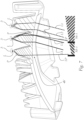
- Fig. 1 shows an perspective view of a motorcycle headlamp 2 according to the present invention.
- the motorcycle headlamp 2 comprises an illumination device 1.
- the headlamp 2 can typically comprise further elements like a housing, a clear view screen closing the housing, adjusting devices, screws etc. which are not shown in the figures.
- the illumination device 1 is configured to create a segmented light pattern and comprises: A plurality of light sources 3, wherein at least some of these light sources 3 are configured to be activated independently from each other and a segmented light guide unit 4, comprising a plurality of light guide elements 4a (see also Fig. 2 to Fig. 4 ) and a light homogenization body 4b.
- Each light guide element 4a has a distal end comprising a light entry surface 4a' (see for instance Fig. 2 ) that is configured to receive light L (see Fig. 7 ) from at least one of the plurality of light sources 3.
- the invention also relates to a motorcycle headlamp 2 comprising an illumination device 1 according to the present invention, wherein the vehicle headlamp 2 further comprises a low beam light module 6 for irradiating a low beam light distribution.
- the optic body 5 can be developed into a single collective projection lens, said collective projection lens being configured to project light emitted from the illumination device 1 and the low beam light module 6.
- each light guide element 4a fully extends towards the homogenization body 4b, said extension following at least partially along a main beam direction x of the illumination device 1, wherein the light guide elements 4a are arranged in at least four columns C but no more than twelve columns C and at least three rows R1 to R7 in order to enable a segmentation of the light pattern.
- the cross section of each light guide element 4a continuously increases along its extension starting from its entry surface 4a' towards the light homogenization body 4b, said cross section being measured in a plane that is oriented orthogonal to the main beam direction x.
- the segmented light guide unit 4 is created as a single pieced component by way of molding, in particular injection molding of the plurality of light guide elements 4a together with the light homogenization body 4b.
- the light homogenization body 4b extends along the main beam direction x in order to allow at least partial homogenization of light received from the light guide elements 4a and wherein the light homogenization body 4b comprises a collective light exit surface 4b' for irradiating light L1, L2, L3, L4 received by the light guide elements 4a.
- the light guide elements 4a arranged in the outer left and the outer right column C of contain two light entry surfaces 4a' each. This allows to align two light sources with a wider segment of the light distribution such that a high light intensity can be achieved despite the wider spatial angle of the respective segment.
- Fig. 1 shows that the illumination device 1 further comprises a low beam optics 6A, for example collimators, a low beam bezel 6B having a cut-off edge 6C and aligned almost horizontally, and a projection lens 5, which is configured to receive the light emitted from the collective light exit surface 4b' of the light homogenization body 4b and to project the segmented light pattern.
- a low beam optics 6A for example collimators
- a low beam bezel 6B having a cut-off edge 6C and aligned almost horizontally
- a projection lens 5 which is configured to receive the light emitted from the collective light exit surface 4b' of the light homogenization body 4b and to project the segmented light pattern.
- said light entry surface is limited by four corners G1a, G1b, G1c, G1d connected by four side edges, namely a left edge Glad, a right edge G1bc, a lower edge Glab and an upper edge G1dc, wherein three out of these four side edges are straight, and wherein the fourth edge differs from the three straight edges by having a rounded protrusion P, said rounded protrusion P increasing the light entrance surface 4a', wherein said fourth edge is either the left or the right edge of the respective light guide element 4a1.
- the rounded protrusion P extends along between 30% and 80% of the length GL of the fourth edge.
- the protrusion P can increase the size of the light entrance surface 4a' between 5% and 30%.
- the extent of the protrusion P can continuously decrease along the extension of the respective light guide element 4a towards the light homogenization body 4b (see for instance Fig. 4 ).
- the protrusion P ends prior to reaching the light homogenization body 4b.
- Each light guide element 4a of the segmented light guide unit 4 is assigned to a specific segment of the light pattern that can be irradiated by the illumination device 1, wherein neighbouring light guide elements 4a are assigned to neighbouring segments, see for instance the segments S3-1 and S-4-1 shown in Fig. 7 .
- neighbouring light guide elements 4a are assigned to neighbouring segments, see for instance the segments S3-1 and S-4-1 shown in Fig. 7 .
- the light L irradiated by the light sources 3 enters the light guide elements 4a, travels towards the homogenization body 4b and leaves the body 4b at its collective light exit surface 4b'.
- the light rays L1 and L2 are ending up (after projection by the projection lens 5 that is not shown in Fig.
- each row R1 to R7 of the light guide element 4a of the segmented light guide unit 4 including the light sources 3 assigned to these rows R1 to R7 can be activated and deactivated independently of each other, wherein the illumination device 1 is configured to be controlled based on a measured bank angle of the motorcycle, wherein the rows are tilted with regard to another and activation and deactivation of the rows R1 to R7 is performed based on the measured bank angle of the motorcycle, in particular in order to add additional light irradiation into an area of a low beam distribution.
- the illumination device 1 is configured to enable the irradiation of a high beam light distribution.
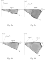
- Fig. 6b shows a scenario wherein the illumination device 1 according to the present invention is tilted due to cornering.
- a motorcycle comprising said illumination device 1 is tilted to the right side by an angle a1 (corresponding with a certain bank angle of the motorcycle).
- the low beam distribution irradiated by a low beam light module 6 will be tilted correspondingly.
- the illumination device 1 can be used to illumination the area that cannot be illuminated by the low beam light module 6 when cornering. It is worth noting that the upper row R1 can be split in two halves, a right and a left half, wherein depending on the inclination (i.e.
- the upper row R1 can be configured to follow the cut-off line and irradiate light upwards for said cut-off line (referred to as HDG-a1 to HDG-a4 in Fig.
- the distribution of the following rows R2 and R5 is elevated upwards followed by the next rows R3 and R6 etc.
- Fig. 8a to 8d show different angles a1 to a4 and corresponding light distributions that can be irradiated by a illumination 1 device in order to support the low beam light module 6 and to complete the low beam distribution despite cornering of the motorcycle.
- Fig. 8a to 8d show different angles a1 to a4 and corresponding light distributions that can be irradiated by a illumination 1 device in order to support the low beam light module 6 and to complete the low beam distribution despite cornering of the motorcycle.
- Fig. 8a the left half of a first row R1 is activated and in Fig. 8b a second row R2 is activated in addition to the left half of the first row R1.
- Fig. 8c shows an additional activation of a third row R3
- Fig. 8d shows an additional activation of a fourth row R4.
- Fig. 8a to 8d also clearly shows slight inhomogeneities between inner and outer segments of the light distribution that correspond to the columns C which occur when no protrusions P are used. These inhomogeneities can be fully compensated by implementation of the protrusions P as described in the present invention.
- the light guide elements 4a can be part of a second group G2 of light guide elements 4a, said second group G2 of light guide elements having a defined geometric shape of the light entry surface 4a', said light entry surface being limited by four corners G2a, G2b, G2c, G2d connected by four side edges, namely a left edge G2ad, a right edge G2bc, a lower edge G2ab and an upper edge G2dc, wherein all four side edges are straight.
- the light entry surface 4a' of each light guide element 4a of the second group G2 has essentially a quadratic shape.
- the number of light guide elements 4a of the first group G1 can amount to at least 33% of the total number of light guide elements 4a of the segmented light guide unit 4.
- the projection lens 5 has an optical axis and a Petzval area, wherein the segmented light guide unit 4 and the projection lens are arranged to each other in such a way that the collective light exit surface 4b' of the segmented light guide unit 4 is positioned in the Petzval area of the projection lens 5.
- the segmented light guide unit 4 and the projection lens 5 are coaxially arranged with the main beam direction x of the illumination device 1.
Landscapes
- Engineering & Computer Science (AREA)
- General Engineering & Computer Science (AREA)
- Physics & Mathematics (AREA)
- Optics & Photonics (AREA)
- Microelectronics & Electronic Packaging (AREA)
- Mechanical Engineering (AREA)
- General Physics & Mathematics (AREA)
- Mathematical Physics (AREA)
- Non-Portable Lighting Devices Or Systems Thereof (AREA)
- Planar Illumination Modules (AREA)
Priority Applications (5)
| Application Number | Priority Date | Filing Date | Title |
|---|---|---|---|
| EP21211988.7A EP4191127A1 (de) | 2021-12-02 | 2021-12-02 | Beleuchtungsvorrichtung für motorradscheinwerfer |
| US17/994,613 US11738819B2 (en) | 2021-12-02 | 2022-11-28 | Illumination device for motorcycle headlamp |
| JP2022191346A JP7383781B2 (ja) | 2021-12-02 | 2022-11-30 | オートバイ用ヘッドランプのための照明装置 |
| KR1020220165327A KR20230083239A (ko) | 2021-12-02 | 2022-12-01 | 모터사이클 헤드램프용 조명 장치 |
| CN202211534990.8A CN116221648A (zh) | 2021-12-02 | 2022-12-02 | 用于摩托车前照灯的照明设备 |
Applications Claiming Priority (1)
| Application Number | Priority Date | Filing Date | Title |
|---|---|---|---|
| EP21211988.7A EP4191127A1 (de) | 2021-12-02 | 2021-12-02 | Beleuchtungsvorrichtung für motorradscheinwerfer |
Publications (1)
| Publication Number | Publication Date |
|---|---|
| EP4191127A1 true EP4191127A1 (de) | 2023-06-07 |
Family
ID=78821055
Family Applications (1)
| Application Number | Title | Priority Date | Filing Date |
|---|---|---|---|
| EP21211988.7A Pending EP4191127A1 (de) | 2021-12-02 | 2021-12-02 | Beleuchtungsvorrichtung für motorradscheinwerfer |
Country Status (5)
| Country | Link |
|---|---|
| US (1) | US11738819B2 (de) |
| EP (1) | EP4191127A1 (de) |
| JP (1) | JP7383781B2 (de) |
| KR (1) | KR20230083239A (de) |
| CN (1) | CN116221648A (de) |
Citations (7)
| Publication number | Priority date | Publication date | Assignee | Title |
|---|---|---|---|---|
| WO2014019912A1 (de) * | 2012-08-03 | 2014-02-06 | Automotive Lighting Reutlingen Gmbh | Lichtleitelement und lichtmodul |
| DE102013200442B3 (de) * | 2013-01-15 | 2014-02-13 | Automotive Lighting Reutlingen Gmbh | Lichtmodul für einen Kraftfahrzeugscheinwerfer, der zur Erzeugung streifenförmiger Lichtverteilungen eingerichtet ist |
| AT513341A1 (de) | 2012-09-03 | 2014-03-15 | Zizala Lichtsysteme Gmbh | Leuchteinheit für einen Scheinwerfer |
| DE102013211878A1 (de) * | 2013-06-24 | 2014-12-24 | Bayerische Motoren Werke Aktiengesellschaft | Scheinwerfer für ein Motorrad |
| EP3339720A1 (de) * | 2016-12-19 | 2018-06-27 | Automotive Lighting Reutlingen GmbH | Primäroptikbaugruppe zum einsatz in einer kraftfahrzeugbeleuchtungseinrichtung und kraftfahrzeugbeleuchtungseinrichtung mit einer solchen primäroptikbaugruppe |
| EP3527876A1 (de) * | 2018-02-19 | 2019-08-21 | ZKW Group GmbH | Kraftfahrzeugscheinwerfer mit lichtleitelementen angeordnet in matrixform |
| DE102018209061A1 (de) * | 2018-06-07 | 2019-12-12 | Osram Gmbh | Optische anordnung für ein fahrzeug, scheinwerfer, fahrzeug und verfahren für die optische anordnung |
Family Cites Families (6)
| Publication number | Priority date | Publication date | Assignee | Title |
|---|---|---|---|---|
| JP2013193562A (ja) * | 2012-03-19 | 2013-09-30 | Yamaha Motor Co Ltd | リーン姿勢で旋回する車両用のサブヘッドライトユニット及びサブヘッドライトシステム、並びにリーン姿勢で旋回する車両 |
| AT518090B1 (de) * | 2015-12-21 | 2017-10-15 | Zkw Group Gmbh | Scheinwerfer für ein Fahrzeug |
| KR102322461B1 (ko) * | 2017-08-08 | 2021-11-05 | 에스엘 주식회사 | 차량용 헤드 램프 |
| FR3074257B1 (fr) * | 2017-11-27 | 2020-11-13 | Valeo Vision | Module lumineux pour l’eclairage et/ou la signalisation d’un vehicule automobile |
| FR3084755B1 (fr) * | 2018-08-02 | 2020-12-18 | Valeo Vision | Piece optique comprenant un bloc avec un dioptre formant plieuse pour deux faisceaux |
| CN215863191U (zh) * | 2018-08-22 | 2022-02-18 | 亮锐控股有限公司 | 用于汽车照明的包括光导的光学设备 |
-
2021
- 2021-12-02 EP EP21211988.7A patent/EP4191127A1/de active Pending
-
2022
- 2022-11-28 US US17/994,613 patent/US11738819B2/en active Active
- 2022-11-30 JP JP2022191346A patent/JP7383781B2/ja active Active
- 2022-12-01 KR KR1020220165327A patent/KR20230083239A/ko unknown
- 2022-12-02 CN CN202211534990.8A patent/CN116221648A/zh active Pending
Patent Citations (7)
| Publication number | Priority date | Publication date | Assignee | Title |
|---|---|---|---|---|
| WO2014019912A1 (de) * | 2012-08-03 | 2014-02-06 | Automotive Lighting Reutlingen Gmbh | Lichtleitelement und lichtmodul |
| AT513341A1 (de) | 2012-09-03 | 2014-03-15 | Zizala Lichtsysteme Gmbh | Leuchteinheit für einen Scheinwerfer |
| DE102013200442B3 (de) * | 2013-01-15 | 2014-02-13 | Automotive Lighting Reutlingen Gmbh | Lichtmodul für einen Kraftfahrzeugscheinwerfer, der zur Erzeugung streifenförmiger Lichtverteilungen eingerichtet ist |
| DE102013211878A1 (de) * | 2013-06-24 | 2014-12-24 | Bayerische Motoren Werke Aktiengesellschaft | Scheinwerfer für ein Motorrad |
| EP3339720A1 (de) * | 2016-12-19 | 2018-06-27 | Automotive Lighting Reutlingen GmbH | Primäroptikbaugruppe zum einsatz in einer kraftfahrzeugbeleuchtungseinrichtung und kraftfahrzeugbeleuchtungseinrichtung mit einer solchen primäroptikbaugruppe |
| EP3527876A1 (de) * | 2018-02-19 | 2019-08-21 | ZKW Group GmbH | Kraftfahrzeugscheinwerfer mit lichtleitelementen angeordnet in matrixform |
| DE102018209061A1 (de) * | 2018-06-07 | 2019-12-12 | Osram Gmbh | Optische anordnung für ein fahrzeug, scheinwerfer, fahrzeug und verfahren für die optische anordnung |
Also Published As
| Publication number | Publication date |
|---|---|
| JP2023082688A (ja) | 2023-06-14 |
| US11738819B2 (en) | 2023-08-29 |
| US20230174183A1 (en) | 2023-06-08 |
| KR20230083239A (ko) | 2023-06-09 |
| JP7383781B2 (ja) | 2023-11-20 |
| CN116221648A (zh) | 2023-06-06 |
Similar Documents
| Publication | Publication Date | Title |
|---|---|---|
| US10232763B1 (en) | Solid state adaptive headlight | |
| JP6594560B2 (ja) | 車両用の投光器 | |
| US10851958B2 (en) | Motor vehicle lighting module, and lighting and/or signalling device provided with such a module | |
| RU2566678C2 (ru) | Осветительный узел | |
| US9732925B2 (en) | Headlight lens with two tunnel sections for separate light entry surfaces for a vehicle headlight | |
| US9453628B2 (en) | Headlight lens for a vehicle headlight | |
| CN107636386B (zh) | 车辆用灯具 | |
| US9719645B2 (en) | Motor vehicle headlight having a complex headlight lens | |
| JP7004849B2 (ja) | 自動車投光装置のライトモジュール | |
| US11280463B2 (en) | Projection apparatus, lighting module and motor vehicle headlamp consisting of micro-optical systems | |
| RU2762067C1 (ru) | Фара дальнего света | |
| JP7256017B2 (ja) | 2つの成形層を装備した一次光学素子を備える光モジュール | |
| CN110778977B (zh) | 包括多个光源的矩阵阵列和双焦点光学系统的发光模块 | |
| CN112204301B (zh) | 用于前照灯的前场光模块 | |
| CN109488986B (zh) | 用于机动车辆的光模块和设置有这种模块的照明和/或信号指示装置 | |
| EP4191127A1 (de) | Beleuchtungsvorrichtung für motorradscheinwerfer | |
| JP2019149369A (ja) | 自動車両用の光学モジュール | |
| US10107466B2 (en) | Headlight lens for a vehicle headlight | |
| US11719403B2 (en) | Primary optics for motorcycle headlamp | |
| KR102629481B1 (ko) | 위치 천이되는 복수의 패턴들로 구성되는 쉴드를 포함하는 렌즈복합체를 포함하는 자동차 헤드라이트용 조명 모듈 | |
| KR20210037250A (ko) | 차량용 헤드램프 | |
| CN114263889B (zh) | 高分辨率车辆前照灯 |
Legal Events
| Date | Code | Title | Description |
|---|---|---|---|
| PUAI | Public reference made under article 153(3) epc to a published international application that has entered the european phase |
Free format text: ORIGINAL CODE: 0009012 |
|
| STAA | Information on the status of an ep patent application or granted ep patent |
Free format text: STATUS: THE APPLICATION HAS BEEN PUBLISHED |
|
| AK | Designated contracting states |
Kind code of ref document: A1 Designated state(s): AL AT BE BG CH CY CZ DE DK EE ES FI FR GB GR HR HU IE IS IT LI LT LU LV MC MK MT NL NO PL PT RO RS SE SI SK SM TR |
|
| STAA | Information on the status of an ep patent application or granted ep patent |
Free format text: STATUS: REQUEST FOR EXAMINATION WAS MADE |
|
| 17P | Request for examination filed |
Effective date: 20231130 |
|
| RBV | Designated contracting states (corrected) |
Designated state(s): AL AT BE BG CH CY CZ DE DK EE ES FI FR GB GR HR HU IE IS IT LI LT LU LV MC MK MT NL NO PL PT RO RS SE SI SK SM TR |
|
| GRAP | Despatch of communication of intention to grant a patent |
Free format text: ORIGINAL CODE: EPIDOSNIGR1 |
|
| STAA | Information on the status of an ep patent application or granted ep patent |
Free format text: STATUS: GRANT OF PATENT IS INTENDED |
|
| INTG | Intention to grant announced |
Effective date: 20240910 |