EP4191114B1 - Kopplungsvorrichtung - Google Patents
Kopplungsvorrichtung Download PDFInfo
- Publication number
- EP4191114B1 EP4191114B1 EP21212584.3A EP21212584A EP4191114B1 EP 4191114 B1 EP4191114 B1 EP 4191114B1 EP 21212584 A EP21212584 A EP 21212584A EP 4191114 B1 EP4191114 B1 EP 4191114B1
- Authority
- EP
- European Patent Office
- Prior art keywords
- piece
- adapter piece
- coupling device
- adapter
- tubular
- Prior art date
- Legal status (The legal status is an assumption and is not a legal conclusion. Google has not performed a legal analysis and makes no representation as to the accuracy of the status listed.)
- Active
Links
Images
Classifications
-
- F—MECHANICAL ENGINEERING; LIGHTING; HEATING; WEAPONS; BLASTING
- F28—HEAT EXCHANGE IN GENERAL
- F28F—DETAILS OF HEAT-EXCHANGE AND HEAT-TRANSFER APPARATUS, OF GENERAL APPLICATION
- F28F9/00—Casings; Header boxes; Auxiliary supports for elements; Auxiliary members within casings
- F28F9/02—Header boxes; End plates
- F28F9/0246—Arrangements for connecting header boxes with flow lines
- F28F9/0256—Arrangements for coupling connectors with flow lines
- F28F9/0258—Arrangements for coupling connectors with flow lines of quick acting type, e.g. with snap action
-
- F—MECHANICAL ENGINEERING; LIGHTING; HEATING; WEAPONS; BLASTING
- F16—ENGINEERING ELEMENTS AND UNITS; GENERAL MEASURES FOR PRODUCING AND MAINTAINING EFFECTIVE FUNCTIONING OF MACHINES OR INSTALLATIONS; THERMAL INSULATION IN GENERAL
- F16L—PIPES; JOINTS OR FITTINGS FOR PIPES; SUPPORTS FOR PIPES, CABLES OR PROTECTIVE TUBING; MEANS FOR THERMAL INSULATION IN GENERAL
- F16L37/00—Couplings of the quick-acting type
- F16L37/08—Couplings of the quick-acting type in which the connection between abutting or axially overlapping ends is maintained by locking members
- F16L37/084—Couplings of the quick-acting type in which the connection between abutting or axially overlapping ends is maintained by locking members combined with automatic locking
- F16L37/098—Couplings of the quick-acting type in which the connection between abutting or axially overlapping ends is maintained by locking members combined with automatic locking by means of flexible hooks
- F16L37/0985—Couplings of the quick-acting type in which the connection between abutting or axially overlapping ends is maintained by locking members combined with automatic locking by means of flexible hooks the flexible hook extending radially inwardly from an outer part and engaging a bead, recess or the like on an inner part
-
- F—MECHANICAL ENGINEERING; LIGHTING; HEATING; WEAPONS; BLASTING
- F01—MACHINES OR ENGINES IN GENERAL; ENGINE PLANTS IN GENERAL; STEAM ENGINES
- F01P—COOLING OF MACHINES OR ENGINES IN GENERAL; COOLING OF INTERNAL-COMBUSTION ENGINES
- F01P11/00—Component parts, details, or accessories not provided for in, or of interest apart from, groups F01P1/00 - F01P9/00
- F01P11/04—Arrangements of liquid pipes or hoses
Definitions
- the invention relates to a coupling device according to the generic term of claim 1.
- EP 2 946 136 A1 which discloses the preamble of claim 1, discloses a coupling device with a metallic pipe of a heat exchanger and a metallic adapter.
- the pipe and the adapter are connected to each other by brazing, which is disadvantageously time-consuming and cost-intensive.
- a VDA-Connector can then be fitted to the adapter.
- the VDA-Connector is a connector standardized by the German Association of the Automotive Industry for devices in a motor vehicle.
- EP 2 293 004 A2 discloses a coupling assembly for a vehicle air-conditioning unit comprises a tubular component and a coupling component for coupling the tubular component to a connecting part.
- US 2018 / 0 283 589 A1 relates to a male portion of a quick VDA-connector for connecting a metallic hose to another component or to another hose.
- US 2015 / 0 176 729 A1 discloses a hydraulic tube for a vehicle with a pipe having a pipe rib, and with a connector fitted around the pipe such that the pipe extends through opposite ends of the connector.
- FR 2 819 573 A1 discloses a coupling device with a male piece, a female piece and a bayonet joint.
- the bayonet joint connects the female piece and the male piece like a bayonet via a bayonet joint.
- a coupling device for connecting a heat exchanger to a standardized connector.
- the standardized connector is a VDA-Connector standardized by the German Association of the Automotive Industry for devices in a motor vehicle.
- the coupling device thereby comprises a tubular piece and a hollow cylindrical adapter piece.
- the tubular piece is inserted into the adapter piece i.e. the adapter piece is slid onto the tubular piece along a mounting axis to a predetermined distance and the tubular piece is axially and preferably detachable fixed to the adapter piece.
- the coupling device comprises a form-fitting unit and the form-fitting unit non-rotarably fixes the adapter piece to the tubular piece.
- the terms “radial” and “axial” and “circumferential” always refer to the mounting axis.
- the tubular piece and the adapter piece are non-rotarably fixed and a material connection between the tubular piece and the adapter piece can be avoided. This can simplify the manufacture of the coupling device and reduce manufacturing costs. Moreover, material-non-bondable materials can be used for the tubular piece and the adapter piece.
- the tubular piece may be formed from metal and the adapter piece may be formed from plastic.
- the form-fitting unit may comprise a first form-fitting element and a second form-fitting element.
- the first form-fitting element may be formed on the tubular piece, and the second form-fitting element may be formed on the adapter piece.
- the first form-fitting element and the second form-fitting element may be axially insertable into one another and can be non-rotatably fixed to one another in a rotationally fixed manner in a circumferential direction surrounding the mounting axis. In this way, during assembly of the coupling device, the form-fitting elements can be inserted into one another and subsequently non-rotatably fixed the adapter piece to the tubular piece.
- the tubular piece comprises an outer stop projection and the adapter piece comprises an inner stop recess.
- the stop projection is formed externally on the tubular piece and the stop recess is formed internally in the adapter piece.
- the stop projection and the stop recess are each formed to surround the mounting axis at least in certain regions. The stop projection thereby engages radially in the stop recess and, as a result, the adapter piece lies on the tubular piece axially in one direction. In other words, the stop projection and the stop recess form an axial stop for the adapter piece on the rotor piece.
- the tubular piece transversely to the mounting axis, contains an outer contour lying on the outside of the stop projection and the adapter piece contains an inner contour lying on the inside of the stop recess.
- the outer contour and the inner contour fits tightly to each other and are rotationally asymmetrical.
- the inner contour and the outer contour enable the stop projection and the stop recess and, correspondingly, the tubular piece and the adapter piece to be non-rotatably fixed to one another in a circumferential direction surrounding the mounting axis.
- first form-fitting element may be represented by the outer contour of the tubular piece at the stop projection and the second form-fitting element may be represented by the inner contour of the adapter piece at the stop recess.
- the outer contour of the tubular piece at the stop projection and the inner contour of the adapter piece at the stop recess may each be polygonal.
- the tubular piece comprises a locking groove and the adapter piece comprises at least one locking element.
- the locking groove is formed on the outside of the tubular piece and surrounds at least in regions the mounting axis.
- the at least one locking element is axially aligned and is radially resiliently formed on the adapter piece.
- the at least one locking element engages radially in the locking groove and the adapter piece is axially and preferably detachable fixed to the tubular piece.
- a radially inwardly directed projection may be formed at the end of the at least one locking element. The projection may engage radially in the locking groove, and thereby the at least one locking element may be securely fixed in the locking groove.
- a plurality of locking elements may be formed on the adapter piece and may be arranged side by side in a circumferential direction surrounding the mounting axis.
- the plurality of locking elements may be formed, for example, on the longitudinal end of the adapter piece by axially aligned cuts.
- the coupling device may comprise a hollow cylindrical standardized connector.
- the adapter piece is then inserted into the standardized connector along the mounting axis.
- the standardized connector can then be axially and preferably detachable fixed to the adapter piece.
- the standardized connector may be a VDA-Connector, as already described above.
- An outer contour of the adapter piece can be adapted to an inner contour of the standardized connector in such a way that the adapter piece and the standardized connector can be axially fixed to each other.
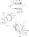
- Fig. 1 shows a sectional view of a coupling device 1 according to the invention with a tubular piece 2 and a hollow cylindrical adapter piece 3.
- the tubular piece 2 is insertable into the adapter piece 3 along a mounting axis MA.
- the tubular piece 2 is made of metal and the adapter piece 3 is made of plastic.
- Fig. 2 shows a view of the tubular piece 2 and Fig. 3 shows a view of the adapter piece 3.
- the tubular piece 2 contains a locking groove 4 and the adapter piece 3 contains a plurality of locking elements 5.
- the locking groove 4 is formed on the outside of the tubular piece 2 and surrounds the mounting axis MA.
- the locking elements 5 are arranged side by side on the adapter piece 3 in a circumferential direction UR surrounding the mounting axis MA, and are separated by a plurality of axially aligned cuts 6. As a result, the locking elements 5 are axially aligned and are radial resilient. As shown in Fig. 1 , the locking elements 5 engage radially in the locking groove 4 and axially and preferably detachable fix the adapter piece 3 to the tubular piece 2.
- the tubular piece 2 also contains a stop projection 7 surrounding the mounting axis MA and the adapter piece 3 contains a stop recess 8 surrounding the mounting axis MA.
- the stop projection 7 is formed on the outside of the tubular piece 2 and the stop recess 8 is formed on the inside of the adapter piece 3. As shown in Fig. 1 , the stop projection 7 and the stop recess 8 abut axially on one another, so that the stop projection 7 and the stop recess 8 form an axial stop for the adapter piece 3 on the tubular piece 2.
- the tubular piece 2 contains a polygonal outer contour 9 at the stop projection 7 and the adapter piece 3 contains a polygonal inner contour 10 at the stop recess 8.
- the outer contour 9 and the inner contour 10 are adjacent to each other and are rotationally asymmetrical.
- the outer contour 9 and the inner contour 10 prevent the adapter piece 3 from rotating against the tubular piece 3.
- the tubular piece 2 and the adapter piece 3 are non-rotatably fixed to each other.
- the outer contour 9 of the tubular piece 2 at the stop projection 7 forms a first form-fitting element 11 of a form-fitting unit 13
- the inner contour 10 of the adapter piece 3 at the stop recess 8 forms a second form-fitting element 12 of the form-fitting unit 13.
- the tubular piece 2 and the adapter piece 3 are non-rotatably fixed and a conventionally necessary material-boding between the tubular piece 2 and the adapter piece 3 can be avoided. This can simplify the manufacture of the coupling device 1.
- the coupling device 1 is provided for connecting a heat exchanger of a motor vehicle to a standardized connector.
- the tubular piece 2 may form a part of the heat exchanger and the adapter piece 3 may be adapted with its outer contour to an inner contour of the standardized connector.
- the standardized connector may in particular be a VDA-Connector as described above.
Landscapes
- Engineering & Computer Science (AREA)
- General Engineering & Computer Science (AREA)
- Mechanical Engineering (AREA)
- Physics & Mathematics (AREA)
- Thermal Sciences (AREA)
- Quick-Acting Or Multi-Walled Pipe Joints (AREA)
Claims (8)
- Kopplungsvorrichtung (1) zum Anschluss eines Wärmetauschers an einen Normstecker,- wobei die Kopplungsvorrichtung (1) ein Rohrstück (2) und ein hohlzylindrisches Adapterstück (3) umfasst,- wobei das Rohrstück (2) entlang einer Montageachse (MA) bis zu einem vorbestimmten Abstand in das Adapterstück (3) eingesetzt und axial am Adapterstück (3) befestigt ist,- wobei die Kopplungsvorrichtung (1) eine Formschlusseinheit (13) enthält und die Formschlusseinheit (13) das Adapterstück (3) drehfest an dem Rohrstück (2) befestigt,- wobei das Rohrstück (2) einen äußeren Anschlagvorsprung (7) enthält, der die Montageachse (MA) zumindest teilweise umgibt,- wobei das Adapterstück (3) eine innere Anschlagaussparung (8) enthält, die die Montageachse (MA) zumindest teilweise umgibt, und- wobei der Anschlagvorsprung (7) radial in die Anschlagaussparung (8) eingreift und dadurch das Adapterstück (3) axial an dem Rohrstück (2) anliegt,dadurch gekennzeichnet,- dass das Rohrstück (2) eine quer zur Montageachse (MA) angeordnete und außen am Anschlagvorsprung (7) liegende Außenkontur (9) enthält,- dass das Adapterstück (3) eine quer zur Montageachse (MA) angeordnete und innen an der Anschlagaussparung (8) liegende Innenkontur (10) enthält,- dass die Außenkontur (9) und die Innenkontur (10) aneinanderstoßen und rotationsasymmetrisch sind.
- Kopplungsvorrichtung nach Anspruch 1,
dadurch gekennzeichnet,
dass das Rohrstück (2) aus Metall hergestellt ist und das Adapterstück (3) aus Kunststoff hergestellt ist. - Kopplungsvorrichtung nach Anspruch 1 oder 2,
dadurch gekennzeichnet,- dass die Formschlusseinheit (13) ein erstes Formschlusselement (11) und ein zweites Formschlusselement (12) umfasst,- dass das erste Formschlusselement (11) an dem Rohrstück (2) gebildet ist und das zweite Formschlusselement (12) an dem Adapterstück (3) gebildet ist, und- dass das erste Formschlusselement (11) und das zweite Formschlusselement (13) entlang der Montageachse (MA) ineinander einsetzbar sind und in einer die Montageachse (MA) umgebenden Umfangsrichtung (UR) formschlüssig ineinandergreifen. - Kopplungsvorrichtung nach Anspruch 3,
dadurch gekennzeichnet,
dass das erste Formschlusselement (11) durch die Außenkontur (9) des Rohrstücks (2) an dem Anschlagvorsprung (7) gebildet ist und das zweite Formschlusselement (12) durch die Innenkontur (10) des Adapterstücks (3) an der Anschlagaussparung (8) gebildet ist. - Kopplungsvorrichtung nach einem der Ansprüche 1 bis 4,
dadurch gekennzeichnet,
dass die Außenkontur (9) des Rohrstücks (2) am Anschlagvorsprung (7) und die Innenkontur (10) des Adapterstücks (3) an der Anschlagaussparung (8) jeweils polygonal sind. - Kopplungsvorrichtung nach einem der vorstehenden Ansprüche,
dadurch gekennzeichnet,- dass das Rohrstück (2) eine die Montageachse (MA) zumindest bereichsweise umlaufende äußere Verriegelungsnut (4) enthält und das Adapterstück (3) mindestens ein axial ausgerichtetes federndes Verriegelungselement (5) enthält, und- dass das mindestens eine Verriegelungselement (5) des Adapterstücks (3) radial in die Verriegelungsnut (4) des Rohrstücks (2) eingreift und dadurch das Adapterstück (3) axial an dem Rohrstück (2) befestigt ist. - Kopplungsvorrichtung nach einem der vorstehenden Ansprüche und ein hohlzylindrischer Normstecker, dadurch gekennzeichnet, dass das Adapterstück (3) entlang der Montageachse (MA) in den Normstecker eingesetzt ist und- dass der Normstecker axial an dem Adapterstück (3) befestigt ist.
- Kopplungsvorrichtung nach Anspruch 7,
dadurch gekennzeichnet,
dass eine Außenkontur des Adapterstücks (3) an eine Innenkontur des Normsteckers derart angepasst ist, sodass das Adapterstück (3) und der Normstecker axial aneinander befestigt werden können.
Priority Applications (1)
| Application Number | Priority Date | Filing Date | Title |
|---|---|---|---|
| EP21212584.3A EP4191114B1 (de) | 2021-12-06 | 2021-12-06 | Kopplungsvorrichtung |
Applications Claiming Priority (1)
| Application Number | Priority Date | Filing Date | Title |
|---|---|---|---|
| EP21212584.3A EP4191114B1 (de) | 2021-12-06 | 2021-12-06 | Kopplungsvorrichtung |
Publications (2)
| Publication Number | Publication Date |
|---|---|
| EP4191114A1 EP4191114A1 (de) | 2023-06-07 |
| EP4191114B1 true EP4191114B1 (de) | 2024-07-24 |
Family
ID=78822641
Family Applications (1)
| Application Number | Title | Priority Date | Filing Date |
|---|---|---|---|
| EP21212584.3A Active EP4191114B1 (de) | 2021-12-06 | 2021-12-06 | Kopplungsvorrichtung |
Country Status (1)
| Country | Link |
|---|---|
| EP (1) | EP4191114B1 (de) |
Family Cites Families (5)
| Publication number | Priority date | Publication date | Assignee | Title |
|---|---|---|---|---|
| FR2819573B1 (fr) * | 2001-01-17 | 2003-04-04 | Pafex France | Raccord d'accouplement rapide |
| DE102009036463B4 (de) * | 2009-07-13 | 2023-01-26 | Valeo Klimasysteme Gmbh | Fahrzeug-Klimaanlage und Verfahren zur Kopplung eines Rohrelements einer Fahrzeug-Klimaanlage |
| FR3001024B1 (fr) | 2013-01-17 | 2015-12-25 | Delphi Automotive Systems Lux | Dispositif de connexion rapide. |
| KR101519275B1 (ko) * | 2013-12-20 | 2015-05-11 | 현대자동차주식회사 | 차량용 유압튜브 |
| FR3064713B1 (fr) * | 2017-03-30 | 2020-07-17 | Akwel Sweden Ab | Procede de fabrication d'un agencement fluidique et agencement fluidique associe |
-
2021
- 2021-12-06 EP EP21212584.3A patent/EP4191114B1/de active Active
Also Published As
| Publication number | Publication date |
|---|---|
| EP4191114A1 (de) | 2023-06-07 |
Similar Documents
| Publication | Publication Date | Title |
|---|---|---|
| US6474698B2 (en) | Connection piece for a heat exchanger | |
| KR100362825B1 (ko) | 신속접속기 | |
| US5857718A (en) | Arrangement for connecting a metal pipe to a receiving sleeve | |
| US20080036202A1 (en) | Hose coupling with molded seal insert | |
| KR20060106894A (ko) | 파이프조인트장치 및 그의 제조방법 | |
| US11788657B2 (en) | Liquid line with a plastic corrugated hose | |
| WO2019145749A1 (en) | A coolant line of a refrigerant circuit and method of manufacturing thereof | |
| EP1692426B1 (de) | Schnellverbindungsrohrkupplung | |
| JPH07110092A (ja) | 2つの流体導管を接続するプラグイン方式継手 | |
| US20060119098A1 (en) | Pipe Joint Structures and Methods of Manufacturing Such Stuctures | |
| US20030080564A1 (en) | Pipe joint assembly and method for assembling the same | |
| EP4191114B1 (de) | Kopplungsvorrichtung | |
| US7086668B2 (en) | Coupling assembly | |
| EP1070899B1 (de) | Verbindungsstruktur | |
| US6439619B1 (en) | Pipe flange clocking | |
| WO2008077013A2 (en) | Connection of tubes for air conditioning and seal adapted thereto | |
| EP0174070B1 (de) | Geformte Kupplungseinrichtung für flüssiges (oder gasförmiges) Medium | |
| EP1741967A1 (de) | Schnellkupplungsvorrichtung für kraftfahrzeugleitungen | |
| EP1602870A1 (de) | Kupplung zur Verbindung eines Rohrs mit einem Schlauch | |
| CN114222871A (zh) | 传动轴及其制造方法 | |
| US6186559B1 (en) | Tube coupling assembly | |
| US11472467B2 (en) | Steering shaft for a motor vehicle and method for the production thereof | |
| EP1298376B1 (de) | Anordnung und Verfahren zum Verbinden eines Anschlussstückes mit einem Verbundschlauch | |
| EP3875826B1 (de) | Kupplungsanordnung für eine klimaanlage eines fahrzeugs | |
| GB2138527A (en) | Improvements in or relating to branched elastomeric hose |
Legal Events
| Date | Code | Title | Description |
|---|---|---|---|
| PUAI | Public reference made under article 153(3) epc to a published international application that has entered the european phase |
Free format text: ORIGINAL CODE: 0009012 |
|
| STAA | Information on the status of an ep patent application or granted ep patent |
Free format text: STATUS: THE APPLICATION HAS BEEN PUBLISHED |
|
| AK | Designated contracting states |
Kind code of ref document: A1 Designated state(s): AL AT BE BG CH CY CZ DE DK EE ES FI FR GB GR HR HU IE IS IT LI LT LU LV MC MK MT NL NO PL PT RO RS SE SI SK SM TR |
|
| STAA | Information on the status of an ep patent application or granted ep patent |
Free format text: STATUS: REQUEST FOR EXAMINATION WAS MADE |
|
| 17P | Request for examination filed |
Effective date: 20230912 |
|
| RBV | Designated contracting states (corrected) |
Designated state(s): AL AT BE BG CH CY CZ DE DK EE ES FI FR GB GR HR HU IE IS IT LI LT LU LV MC MK MT NL NO PL PT RO RS SE SI SK SM TR |
|
| GRAP | Despatch of communication of intention to grant a patent |
Free format text: ORIGINAL CODE: EPIDOSNIGR1 |
|
| STAA | Information on the status of an ep patent application or granted ep patent |
Free format text: STATUS: GRANT OF PATENT IS INTENDED |
|
| INTG | Intention to grant announced |
Effective date: 20240313 |
|
| GRAS | Grant fee paid |
Free format text: ORIGINAL CODE: EPIDOSNIGR3 |
|
| GRAA | (expected) grant |
Free format text: ORIGINAL CODE: 0009210 |
|
| STAA | Information on the status of an ep patent application or granted ep patent |
Free format text: STATUS: THE PATENT HAS BEEN GRANTED |
|
| AK | Designated contracting states |
Kind code of ref document: B1 Designated state(s): AL AT BE BG CH CY CZ DE DK EE ES FI FR GB GR HR HU IE IS IT LI LT LU LV MC MK MT NL NO PL PT RO RS SE SI SK SM TR |
|
| REG | Reference to a national code |
Ref country code: GB Ref legal event code: FG4D |
|
| REG | Reference to a national code |
Ref country code: CH Ref legal event code: EP |
|
| REG | Reference to a national code |
Ref country code: DE Ref legal event code: R096 Ref document number: 602021016089 Country of ref document: DE |
|
| REG | Reference to a national code |
Ref country code: IE Ref legal event code: FG4D |
|
| REG | Reference to a national code |
Ref country code: LT Ref legal event code: MG9D |
|
| REG | Reference to a national code |
Ref country code: NL Ref legal event code: MP Effective date: 20240724 |
|
| PG25 | Lapsed in a contracting state [announced via postgrant information from national office to epo] |
Ref country code: PT Free format text: LAPSE BECAUSE OF FAILURE TO SUBMIT A TRANSLATION OF THE DESCRIPTION OR TO PAY THE FEE WITHIN THE PRESCRIBED TIME-LIMIT Effective date: 20241125 |
|
| REG | Reference to a national code |
Ref country code: AT Ref legal event code: MK05 Ref document number: 1706568 Country of ref document: AT Kind code of ref document: T Effective date: 20240724 |
|
| PG25 | Lapsed in a contracting state [announced via postgrant information from national office to epo] |
Ref country code: NL Free format text: LAPSE BECAUSE OF FAILURE TO SUBMIT A TRANSLATION OF THE DESCRIPTION OR TO PAY THE FEE WITHIN THE PRESCRIBED TIME-LIMIT Effective date: 20240724 |
|
| PG25 | Lapsed in a contracting state [announced via postgrant information from national office to epo] |
Ref country code: PT Free format text: LAPSE BECAUSE OF FAILURE TO SUBMIT A TRANSLATION OF THE DESCRIPTION OR TO PAY THE FEE WITHIN THE PRESCRIBED TIME-LIMIT Effective date: 20241125 Ref country code: NL Free format text: LAPSE BECAUSE OF FAILURE TO SUBMIT A TRANSLATION OF THE DESCRIPTION OR TO PAY THE FEE WITHIN THE PRESCRIBED TIME-LIMIT Effective date: 20240724 |
|
| PG25 | Lapsed in a contracting state [announced via postgrant information from national office to epo] |
Ref country code: NO Free format text: LAPSE BECAUSE OF FAILURE TO SUBMIT A TRANSLATION OF THE DESCRIPTION OR TO PAY THE FEE WITHIN THE PRESCRIBED TIME-LIMIT Effective date: 20241024 |
|
| PG25 | Lapsed in a contracting state [announced via postgrant information from national office to epo] |
Ref country code: FI Free format text: LAPSE BECAUSE OF FAILURE TO SUBMIT A TRANSLATION OF THE DESCRIPTION OR TO PAY THE FEE WITHIN THE PRESCRIBED TIME-LIMIT Effective date: 20240724 Ref country code: GR Free format text: LAPSE BECAUSE OF FAILURE TO SUBMIT A TRANSLATION OF THE DESCRIPTION OR TO PAY THE FEE WITHIN THE PRESCRIBED TIME-LIMIT Effective date: 20241025 Ref country code: PL Free format text: LAPSE BECAUSE OF FAILURE TO SUBMIT A TRANSLATION OF THE DESCRIPTION OR TO PAY THE FEE WITHIN THE PRESCRIBED TIME-LIMIT Effective date: 20240724 |
|
| PG25 | Lapsed in a contracting state [announced via postgrant information from national office to epo] |
Ref country code: BG Free format text: LAPSE BECAUSE OF FAILURE TO SUBMIT A TRANSLATION OF THE DESCRIPTION OR TO PAY THE FEE WITHIN THE PRESCRIBED TIME-LIMIT Effective date: 20240724 |
|
| PG25 | Lapsed in a contracting state [announced via postgrant information from national office to epo] |
Ref country code: LV Free format text: LAPSE BECAUSE OF FAILURE TO SUBMIT A TRANSLATION OF THE DESCRIPTION OR TO PAY THE FEE WITHIN THE PRESCRIBED TIME-LIMIT Effective date: 20240724 |
|
| PG25 | Lapsed in a contracting state [announced via postgrant information from national office to epo] |
Ref country code: AT Free format text: LAPSE BECAUSE OF FAILURE TO SUBMIT A TRANSLATION OF THE DESCRIPTION OR TO PAY THE FEE WITHIN THE PRESCRIBED TIME-LIMIT Effective date: 20240724 Ref country code: IS Free format text: LAPSE BECAUSE OF FAILURE TO SUBMIT A TRANSLATION OF THE DESCRIPTION OR TO PAY THE FEE WITHIN THE PRESCRIBED TIME-LIMIT Effective date: 20241124 |
|
| PG25 | Lapsed in a contracting state [announced via postgrant information from national office to epo] |
Ref country code: HR Free format text: LAPSE BECAUSE OF FAILURE TO SUBMIT A TRANSLATION OF THE DESCRIPTION OR TO PAY THE FEE WITHIN THE PRESCRIBED TIME-LIMIT Effective date: 20240724 |
|
| PG25 | Lapsed in a contracting state [announced via postgrant information from national office to epo] |
Ref country code: RS Free format text: LAPSE BECAUSE OF FAILURE TO SUBMIT A TRANSLATION OF THE DESCRIPTION OR TO PAY THE FEE WITHIN THE PRESCRIBED TIME-LIMIT Effective date: 20241024 Ref country code: ES Free format text: LAPSE BECAUSE OF FAILURE TO SUBMIT A TRANSLATION OF THE DESCRIPTION OR TO PAY THE FEE WITHIN THE PRESCRIBED TIME-LIMIT Effective date: 20240724 |
|
| PG25 | Lapsed in a contracting state [announced via postgrant information from national office to epo] |
Ref country code: RS Free format text: LAPSE BECAUSE OF FAILURE TO SUBMIT A TRANSLATION OF THE DESCRIPTION OR TO PAY THE FEE WITHIN THE PRESCRIBED TIME-LIMIT Effective date: 20241024 Ref country code: PL Free format text: LAPSE BECAUSE OF FAILURE TO SUBMIT A TRANSLATION OF THE DESCRIPTION OR TO PAY THE FEE WITHIN THE PRESCRIBED TIME-LIMIT Effective date: 20240724 Ref country code: NO Free format text: LAPSE BECAUSE OF FAILURE TO SUBMIT A TRANSLATION OF THE DESCRIPTION OR TO PAY THE FEE WITHIN THE PRESCRIBED TIME-LIMIT Effective date: 20241024 Ref country code: LV Free format text: LAPSE BECAUSE OF FAILURE TO SUBMIT A TRANSLATION OF THE DESCRIPTION OR TO PAY THE FEE WITHIN THE PRESCRIBED TIME-LIMIT Effective date: 20240724 Ref country code: IS Free format text: LAPSE BECAUSE OF FAILURE TO SUBMIT A TRANSLATION OF THE DESCRIPTION OR TO PAY THE FEE WITHIN THE PRESCRIBED TIME-LIMIT Effective date: 20241124 Ref country code: HR Free format text: LAPSE BECAUSE OF FAILURE TO SUBMIT A TRANSLATION OF THE DESCRIPTION OR TO PAY THE FEE WITHIN THE PRESCRIBED TIME-LIMIT Effective date: 20240724 Ref country code: GR Free format text: LAPSE BECAUSE OF FAILURE TO SUBMIT A TRANSLATION OF THE DESCRIPTION OR TO PAY THE FEE WITHIN THE PRESCRIBED TIME-LIMIT Effective date: 20241025 Ref country code: FI Free format text: LAPSE BECAUSE OF FAILURE TO SUBMIT A TRANSLATION OF THE DESCRIPTION OR TO PAY THE FEE WITHIN THE PRESCRIBED TIME-LIMIT Effective date: 20240724 Ref country code: ES Free format text: LAPSE BECAUSE OF FAILURE TO SUBMIT A TRANSLATION OF THE DESCRIPTION OR TO PAY THE FEE WITHIN THE PRESCRIBED TIME-LIMIT Effective date: 20240724 Ref country code: BG Free format text: LAPSE BECAUSE OF FAILURE TO SUBMIT A TRANSLATION OF THE DESCRIPTION OR TO PAY THE FEE WITHIN THE PRESCRIBED TIME-LIMIT Effective date: 20240724 Ref country code: AT Free format text: LAPSE BECAUSE OF FAILURE TO SUBMIT A TRANSLATION OF THE DESCRIPTION OR TO PAY THE FEE WITHIN THE PRESCRIBED TIME-LIMIT Effective date: 20240724 |
|
| PG25 | Lapsed in a contracting state [announced via postgrant information from national office to epo] |
Ref country code: SM Free format text: LAPSE BECAUSE OF FAILURE TO SUBMIT A TRANSLATION OF THE DESCRIPTION OR TO PAY THE FEE WITHIN THE PRESCRIBED TIME-LIMIT Effective date: 20240724 Ref country code: DK Free format text: LAPSE BECAUSE OF FAILURE TO SUBMIT A TRANSLATION OF THE DESCRIPTION OR TO PAY THE FEE WITHIN THE PRESCRIBED TIME-LIMIT Effective date: 20240724 Ref country code: RO Free format text: LAPSE BECAUSE OF FAILURE TO SUBMIT A TRANSLATION OF THE DESCRIPTION OR TO PAY THE FEE WITHIN THE PRESCRIBED TIME-LIMIT Effective date: 20240724 |
|
| PG25 | Lapsed in a contracting state [announced via postgrant information from national office to epo] |
Ref country code: EE Free format text: LAPSE BECAUSE OF FAILURE TO SUBMIT A TRANSLATION OF THE DESCRIPTION OR TO PAY THE FEE WITHIN THE PRESCRIBED TIME-LIMIT Effective date: 20240724 |
|
| PG25 | Lapsed in a contracting state [announced via postgrant information from national office to epo] |
Ref country code: CZ Free format text: LAPSE BECAUSE OF FAILURE TO SUBMIT A TRANSLATION OF THE DESCRIPTION OR TO PAY THE FEE WITHIN THE PRESCRIBED TIME-LIMIT Effective date: 20240724 |
|
| REG | Reference to a national code |
Ref country code: DE Ref legal event code: R097 Ref document number: 602021016089 Country of ref document: DE |
|
| PG25 | Lapsed in a contracting state [announced via postgrant information from national office to epo] |
Ref country code: SK Free format text: LAPSE BECAUSE OF FAILURE TO SUBMIT A TRANSLATION OF THE DESCRIPTION OR TO PAY THE FEE WITHIN THE PRESCRIBED TIME-LIMIT Effective date: 20240724 Ref country code: IT Free format text: LAPSE BECAUSE OF FAILURE TO SUBMIT A TRANSLATION OF THE DESCRIPTION OR TO PAY THE FEE WITHIN THE PRESCRIBED TIME-LIMIT Effective date: 20240724 |
|
| PLBE | No opposition filed within time limit |
Free format text: ORIGINAL CODE: 0009261 |
|
| STAA | Information on the status of an ep patent application or granted ep patent |
Free format text: STATUS: NO OPPOSITION FILED WITHIN TIME LIMIT |
|
| 26N | No opposition filed |
Effective date: 20250425 |
|
| PG25 | Lapsed in a contracting state [announced via postgrant information from national office to epo] |
Ref country code: MC Free format text: LAPSE BECAUSE OF FAILURE TO SUBMIT A TRANSLATION OF THE DESCRIPTION OR TO PAY THE FEE WITHIN THE PRESCRIBED TIME-LIMIT Effective date: 20240724 |
|
| REG | Reference to a national code |
Ref country code: CH Ref legal event code: PL |
|
| PG25 | Lapsed in a contracting state [announced via postgrant information from national office to epo] |
Ref country code: LU Free format text: LAPSE BECAUSE OF NON-PAYMENT OF DUE FEES Effective date: 20241206 |
|
| PG25 | Lapsed in a contracting state [announced via postgrant information from national office to epo] |
Ref country code: SE Free format text: LAPSE BECAUSE OF FAILURE TO SUBMIT A TRANSLATION OF THE DESCRIPTION OR TO PAY THE FEE WITHIN THE PRESCRIBED TIME-LIMIT Effective date: 20240724 |
|
| REG | Reference to a national code |
Ref country code: BE Ref legal event code: MM Effective date: 20241231 |
|
| PG25 | Lapsed in a contracting state [announced via postgrant information from national office to epo] |
Ref country code: BE Free format text: LAPSE BECAUSE OF NON-PAYMENT OF DUE FEES Effective date: 20241231 |
|
| PG25 | Lapsed in a contracting state [announced via postgrant information from national office to epo] |
Ref country code: FR Free format text: LAPSE BECAUSE OF NON-PAYMENT OF DUE FEES Effective date: 20241231 |
|
| PG25 | Lapsed in a contracting state [announced via postgrant information from national office to epo] |
Ref country code: CH Free format text: LAPSE BECAUSE OF NON-PAYMENT OF DUE FEES Effective date: 20241231 |
|
| PG25 | Lapsed in a contracting state [announced via postgrant information from national office to epo] |
Ref country code: IE Free format text: LAPSE BECAUSE OF NON-PAYMENT OF DUE FEES Effective date: 20241206 |
|
| P01 | Opt-out of the competence of the unified patent court (upc) registered |
Free format text: CASE NUMBER: UPC_APP_8059_4191114/2025 Effective date: 20250926 |
|
| PGFP | Annual fee paid to national office [announced via postgrant information from national office to epo] |
Ref country code: DE Payment date: 20251211 Year of fee payment: 5 |
|
| PG25 | Lapsed in a contracting state [announced via postgrant information from national office to epo] |
Ref country code: CY Free format text: LAPSE BECAUSE OF FAILURE TO SUBMIT A TRANSLATION OF THE DESCRIPTION OR TO PAY THE FEE WITHIN THE PRESCRIBED TIME-LIMIT; INVALID AB INITIO Effective date: 20211206 |