EP4191014A2 - Outside-mount window blind consisting of a frame with a control device for adjusting the position of the slats - Google Patents
Outside-mount window blind consisting of a frame with a control device for adjusting the position of the slats Download PDFInfo
- Publication number
- EP4191014A2 EP4191014A2 EP22207827.1A EP22207827A EP4191014A2 EP 4191014 A2 EP4191014 A2 EP 4191014A2 EP 22207827 A EP22207827 A EP 22207827A EP 4191014 A2 EP4191014 A2 EP 4191014A2
- Authority
- EP
- European Patent Office
- Prior art keywords
- cam
- slats
- chain
- slot
- blind
- Prior art date
- Legal status (The legal status is an assumption and is not a legal conclusion. Google has not performed a legal analysis and makes no representation as to the accuracy of the status listed.)
- Granted
Links
Images






Classifications
-
- E—FIXED CONSTRUCTIONS
- E06—DOORS, WINDOWS, SHUTTERS, OR ROLLER BLINDS IN GENERAL; LADDERS
- E06B—FIXED OR MOVABLE CLOSURES FOR OPENINGS IN BUILDINGS, VEHICLES, FENCES OR LIKE ENCLOSURES IN GENERAL, e.g. DOORS, WINDOWS, BLINDS, GATES
- E06B9/00—Screening or protective devices for wall or similar openings, with or without operating or securing mechanisms; Closures of similar construction
-
- E—FIXED CONSTRUCTIONS
- E06—DOORS, WINDOWS, SHUTTERS, OR ROLLER BLINDS IN GENERAL; LADDERS
- E06B—FIXED OR MOVABLE CLOSURES FOR OPENINGS IN BUILDINGS, VEHICLES, FENCES OR LIKE ENCLOSURES IN GENERAL, e.g. DOORS, WINDOWS, BLINDS, GATES
- E06B9/00—Screening or protective devices for wall or similar openings, with or without operating or securing mechanisms; Closures of similar construction
- E06B9/24—Screens or other constructions affording protection against light, especially against sunshine; Similar screens for privacy or appearance; Slat blinds
- E06B9/26—Lamellar or like blinds, e.g. venetian blinds
- E06B9/28—Lamellar or like blinds, e.g. venetian blinds with horizontal lamellae, e.g. non-liftable
- E06B9/30—Lamellar or like blinds, e.g. venetian blinds with horizontal lamellae, e.g. non-liftable liftable
- E06B9/302—Lamellar or like blinds, e.g. venetian blinds with horizontal lamellae, e.g. non-liftable liftable without ladder-tape, e.g. with lazy-tongs, with screw spindle
-
- E—FIXED CONSTRUCTIONS
- E06—DOORS, WINDOWS, SHUTTERS, OR ROLLER BLINDS IN GENERAL; LADDERS
- E06B—FIXED OR MOVABLE CLOSURES FOR OPENINGS IN BUILDINGS, VEHICLES, FENCES OR LIKE ENCLOSURES IN GENERAL, e.g. DOORS, WINDOWS, BLINDS, GATES
- E06B9/00—Screening or protective devices for wall or similar openings, with or without operating or securing mechanisms; Closures of similar construction
- E06B9/24—Screens or other constructions affording protection against light, especially against sunshine; Similar screens for privacy or appearance; Slat blinds
- E06B9/26—Lamellar or like blinds, e.g. venetian blinds
- E06B9/28—Lamellar or like blinds, e.g. venetian blinds with horizontal lamellae, e.g. non-liftable
- E06B9/30—Lamellar or like blinds, e.g. venetian blinds with horizontal lamellae, e.g. non-liftable liftable
- E06B9/32—Operating, guiding, or securing devices therefor
- E06B9/322—Details of operating devices, e.g. pulleys, brakes, spring drums, drives
-
- E—FIXED CONSTRUCTIONS
- E06—DOORS, WINDOWS, SHUTTERS, OR ROLLER BLINDS IN GENERAL; LADDERS
- E06B—FIXED OR MOVABLE CLOSURES FOR OPENINGS IN BUILDINGS, VEHICLES, FENCES OR LIKE ENCLOSURES IN GENERAL, e.g. DOORS, WINDOWS, BLINDS, GATES
- E06B9/00—Screening or protective devices for wall or similar openings, with or without operating or securing mechanisms; Closures of similar construction
- E06B9/24—Screens or other constructions affording protection against light, especially against sunshine; Similar screens for privacy or appearance; Slat blinds
- E06B9/26—Lamellar or like blinds, e.g. venetian blinds
- E06B9/28—Lamellar or like blinds, e.g. venetian blinds with horizontal lamellae, e.g. non-liftable
- E06B9/30—Lamellar or like blinds, e.g. venetian blinds with horizontal lamellae, e.g. non-liftable liftable
- E06B9/32—Operating, guiding, or securing devices therefor
- E06B9/327—Guides for raisable lamellar blinds with horizontal lamellae
-
- E—FIXED CONSTRUCTIONS
- E06—DOORS, WINDOWS, SHUTTERS, OR ROLLER BLINDS IN GENERAL; LADDERS
- E06B—FIXED OR MOVABLE CLOSURES FOR OPENINGS IN BUILDINGS, VEHICLES, FENCES OR LIKE ENCLOSURES IN GENERAL, e.g. DOORS, WINDOWS, BLINDS, GATES
- E06B9/00—Screening or protective devices for wall or similar openings, with or without operating or securing mechanisms; Closures of similar construction
- E06B9/56—Operating, guiding or securing devices or arrangements for roll-type closures; Spring drums; Tape drums; Counterweighting arrangements therefor
- E06B9/58—Guiding devices
-
- E—FIXED CONSTRUCTIONS
- E06—DOORS, WINDOWS, SHUTTERS, OR ROLLER BLINDS IN GENERAL; LADDERS
- E06B—FIXED OR MOVABLE CLOSURES FOR OPENINGS IN BUILDINGS, VEHICLES, FENCES OR LIKE ENCLOSURES IN GENERAL, e.g. DOORS, WINDOWS, BLINDS, GATES
- E06B9/00—Screening or protective devices for wall or similar openings, with or without operating or securing mechanisms; Closures of similar construction
- E06B9/24—Screens or other constructions affording protection against light, especially against sunshine; Similar screens for privacy or appearance; Slat blinds
- E06B9/26—Lamellar or like blinds, e.g. venetian blinds
- E06B9/28—Lamellar or like blinds, e.g. venetian blinds with horizontal lamellae, e.g. non-liftable
- E06B9/30—Lamellar or like blinds, e.g. venetian blinds with horizontal lamellae, e.g. non-liftable liftable
- E06B9/32—Operating, guiding, or securing devices therefor
- E06B9/322—Details of operating devices, e.g. pulleys, brakes, spring drums, drives
- E06B2009/3222—Cordless, i.e. user interface without cords
Definitions
- the invention relates to the guiding of outside-mount window slats of the blind, mounted in particular on inclined windows, with a control device for adjusting their position, i.e. sliding and rotation.
- the slats of the outside-mount window blinds there are basically two systems used.
- the first system so called roller shutters, consists of a storage box arranged in the upper part of the frame in which the individual slats are wound and connected together and they are dropped or raised in the slots of the said side frames.
- the disadvantage of this system is that the slats cannot be individually positioned and they are therefore either pulled down, because of complete shading at night or for safety reasons, or pulled up partially to let some light through, or rolled up to the top position into the storage box when it is desired to keep the window uncovered.
- Such a system is described, for example, in CZ 1993-636 A1 .
- rails are arranged along the sides of the window opening only for guiding the side pins of the slats, the blinds are terminated at the bottom by a massive rail on which the lowering or raising belts are anchored, which pass through the individual slats and which are wound on winding wheels arranged at the top of the assembly.
- the slats are also connected via string ladders, which can also be operated and which can tilt the slats.
- the disadvantage of this system is the relatively low rigidity, which can threaten the compactness of the assembly by strong wind. Furthermore, this system works on the principle of gravity and therefore cannot be used for tilted windows. The slats can be pushed by the bottom rail to the stacking position at the top of the window. Such a system is described, for example, in EP 2669462 A1 , AT 007694 U1 , AT 501293 B1 or DE 29913131 U1 .
- the aim of the invention is to provide an outside-mount window blind consisting of a frame with a control device for adjusting the position of the slats, i.e. a system for both sliding and rotating the slats, where the system has a compact structure which can reliably withstand heavy weather and which would also provide suitable shading for buildings and would be able to reduce the temperature inside without additional air-conditioning means.
- the outside-mount window blind consisting of a frame with a control device for adjusting the position of the slats according to the invention, which is characterised by the fact that the slots are two, made as an side chain slot and a central cam slot, whereas below these slots there is space for the links of a chain in the chain slot and for a cam of a control arm for the position of the slats of the blind in the cam slot, whereas in the cam slot the control arm is placed with the through a cam pin of the cam, whereas the control arm is at its ends provided with at least one arm opening for a chain connecting pin which also connects chain links, whereas the slat of the blind is fixed to the control arm and perpendicular lateral slots protrude from the cam slot at regular intervals and below the cam slot, two flexible little sheets are arranged opposite to the lateral slots, whereas two flexible little sheets are fixed by their fixing parts in the base of the guide rail, the press arms of the flexible little sheets are preloaded towards the bottom surface
- the slat of the blind is arranged such, that on the chain connecting pin put in the chain links and in one of arm openings and on the supporting pin in the other arm opening, the holder is arranged on which the slat is fixed.
- control arms provided with recesses at the edges of their fingers to allow the control arms to fit tightly when the slats of the blind are in the stacked position.
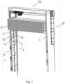
- Fig. 1 shows an outside-mount window blind according to the invention, where all slats of the blind are stacked in a basic position
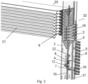
- Fig. 2 shows a detail of the internal arrangement of the control device from Fig. 1
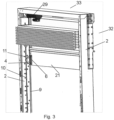
- Fig. 3 is a view of the droping the slats in the initial phase
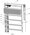
- Fig. 4 is a view of the dropping in the advanced phase
- Fig. 5 is a view of the slats in the final phase of droping, when the slats are in the maximum open position
- Fig. 6 is a view of the slats in the final stage of lowering, but the slats are in the half-open position
- Fig. 1 shows an outside-mount window blind according to the invention, where all slats of the blind are stacked in a basic position
- Fig. 2 shows a detail of the internal arrangement of the control device from Fig. 1
- Fig. 3 is a view of the droping the slats
- FIG. 7 is a detail of the control arm of the slats
- Fig. 8 is a detail of the cam of arm from Fig. 7
- Fig. 9 is a schematic section of the frame according to the line A-A of Fig. 1 with elements of the control device
- Fig. 10 is the chain and control arm assembly corresponding to the arrangement in Fig. 9
- Fig. 11 shows a situation where all the slats in the horizontal position are dropped to the fully shaded position
- Fig. 12 shows a situation where all slats in the vertical position are pulled up to the fully stacked position
- Fig. 13 to 18 show the individual stages of controlling the position of the slats by the arms from Figures 7 and 8 .
- FIG. 1 shows the basic frame 32 for guiding the oitside-mount window slats 21 of the blind 33 operated by the control device 1 for sliding and rotating them. All slats 21 of the blind 33 are here stacked in a packet in the upper base position.
- the basic elements of the device are arranged in two vertical parallel and mirror-symmetrical guide rails 2, each of which is provided with a central cam slot 10 and a side chain slot 9 which, when mounted, is closer to the window glass.
- the control arm 4 of the slats 21 is partially visible, and perpendicular lateral slots 11 project from the cam slots 10 at regular intervals therefrom.
- Fig. 2 shows in detail that each slat 21 has a holder 6 on both sides which is fixed to the control arm 4. Furthermore, the links of the chain 3 in the stacked position and also the control arms 4 in the stacked position are shown. At the side of each guide rails 2 a worm 5, driven via a distribution shaft and an angular motor gearbox is arranged. Flexible little sheets 7, 8, the function of which will be discussed later, are also visible. This worm drive 29 of the worm 5 can be seen in Fig. 3 and is located under the transverse connecting beam.
- Chain connecting pins 16 protrude from the chain 3, and the worm 5 always catches one pin 16 and thus always moves this one pin downwardly when the slats 21 are moved downwardly, and conversely, when the direction of rotation of the worm is reversed, it pulls the chain 3 with the slats 21 upwardly by these chain connecting pins 16.
- Fig. 3 shows the stacked slats 21 and the assembly of stlats 21 of the blind 33 in a state in which the first slat 21 is rotated by the control device 1 to the fully shading position, i.e. perpendicular to the stacked position.
- the mechanism for droping and rotating the slats 21 will be described in detail later.
- the holder 6 on which the slats 21 of the blind 33 are fixed is also clearly visible, and this holder 6 is arranged on the arm 4 via the chain connecting pin 16 and the supporting pin 14. This can be clearly seen in Fig. 10 .
- the slat 21 may be fixed directly on the arm 4, or preferably the slat 21 of the blind 33 may be arranged such that on the chain connecting pin 16 put in the chain links 17, 18 and in one of arm openings 22 and on the supporting pin 14 in the other arm opening 22, the holder 6 is arranged on which the slat 21 is fixed - see Fig. 10 .
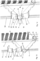
- Fig. 4 shows the situation in the droping phase of the slats 21, when several slats 21 of the blind 33 are lowered to the fully shaded position.
- Both the chain slot 9 and the cam slot 10 can be seen here, as well as perpendicular lateral slots 11 which are arranged at regular intervals.
- slats 21 can also be brought into any slightly open position within the range of 90° where the slats 21 are tilted and when they are shading partially.
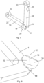
- Fig. 7 shows a detail of the control arm 4. This serves to fix the holder 6 for the slat 21 of the blind 33 and to connect it to the chain 3, thereby also ensuring the rotation of the slat 21 of the blind 33.
- the control arm 4 is substantially V-shaped, consisting of two fingers 31 and at its ends is the control arm 4 provided with chain openings 15 for pins 14, 16 and are provided with recesses 23. The recesses 23 serve to allow stacked control arms 4 to fit tightly together in the stacked position of the blind 33.
- the control arm 4 is provided with a cam 12 mounted on a cam pin 13.
- the cam 12 is cylindrical and its upper face is provided with two wedge sectors 19 and one rectangular flat sector 20 of the full thickness of the cam 12.
- Fig. 9 is a schematic section of the guide rail 2 according to line A-A of Fig. 1 .
- the guide rail 2 consists of a base 27 and a guide rail cover 28.
- the chain 3 is guided in the chain slot 9 of the guide rail 2, the chain 3 consists of a base guide chain links 17 which connect connecting chain links 18 arranged above.
- Through the chain openings 15 of the chain links the chain connecting pins 16 are put in.
- On the chain connecting pin 16 the control arm 4 is put in by one of its arm openings 22, and the cam pin 13 is guided in the cam slot 10.
- In the base 27 of the guide rail 2 there is a storage slot 26 for the fixing parts 24 of the flexible little sheets 7, 8 mentioned in Fig. 2 .
- Fig. 10 is an assembly of two chain links and the control arm 4 corresponding spatially to the arrangement of Fig. 9 .
- the chain 3 consists of guide chain links 17 and connecting chain links 18, the connecting chain link 18 is closer to the control arm 4.
- a chain connecting pin 16 which connects both chain links 17, 18 and also carries at one end the blind slat holder 6 of the slat 21 of the blind 33.
- a supporting pin 14 is arranged for the other end of the blind slat holder 6.
- the wedge sectors 19 of the cam 12 are oriented opposite the fingers 31 of the control arm 4. This is very important for explanation why the cams 12 do not interfere when droping the slats 21 to the shading position or, conversely, when pulling the slats 21 to the stacked position. If the cams 12 were not provided with these wedge sectors 19, the cam would lift and pass under one of the flexible little sheets 7, 8, but against the following flexible little sheet, or stop 25 thereof, preloaded towards the bottom surface of the cam slot 10, the cam 12 and the slat 21 would strike and could not continue in straight direction. This is explained with reference to Figs. 11 and 12 , wherein Fig.
- Fig. 12 shows a situation in which all slats 21 of the blind 33 in the vertical position are pulled up to a fully stacked position.
- the cam 12 of the control arm 4 is oriented so that it has in the indicated direction of movement the wedge sector 19 oriented upwards.
- the lower flexible little sheet 7 is easily passed under by the cam 12, since the press arm 30 is raised from the cam slot 10 and the press arm 30' of the upper flexible sheet 8 is raised due to this wedge sector 19.
- This situation is the same for all the cams 12 of the other slats 21, and therefore, all of them, thus easily rise to the fully stacked position.
- Figs. 13 to 18 show the various stages of operation of the slats 21 of the blind 33. This detailed description follows Fig. 1 to 6 , starting from the situation shown in Fig. 4 .
- the slats 21, originally stacked in the upper part of the frame 32, are after turnover from the horizontal to the vertical position by the worm 5 droped due to the pull of the chain 3, and all of them drop down.
- the most important components of the control device 1 are the control arms 4 with cams 12, wherein the cam 12 is moved by its cam pin 13 in the cam slot 10, under the surface of the guide rail 2.
- the fixing parts 24 of the flexible little sheets 7, 8 are arranged in the storage slots 26, and these, by means of their press arms 30, 30', elastically abut from below the cam slot 10 and are centred relative thereto.
- the press arms 30, 30' of the flexible little sheets 7, 8 are terminated by stops 25 which project away from the guide rail 2 and have the same orientation as the fixing parts 24 of the flexible little sheets 7, 8.
- the basic mechanism for controlling the rotation of the slats 21 of the blind 33 is the interaction between the cam 12, respectively its shaped parts such as the wedge sector 19 and the flat sector 20, and flexible little sheets 7, 8, respectively their stops 25.
- the cam 12 is cylindrical and its upper face is provided with two wedge sectors 19 and one rectangular flat sector 20 which has the full thickness of the cam 12.
- the wedge sectors 19 decrease in thickness from the upper face to the lower face, thereby forming a sharp ramped wedge.
- Fig. 17 shows a situation in which, during the further movement of the chain 3, the cam 12, together with the entire control arm 4 and together with the slat 21 of the blind 33, continues to rotate and, after the complete exit of the lateral slot 11 back into the cam slot 10, the slat 21 reaches a complete horizontal position.
- the cam 12, having already left the lateral slot 11 and rotated, is now oriented with respect to the stop 25 of the upper flexible little sheet 8 by its wedge sector 19, as shown in Fig. 17 .
- phase staged rotation will be the most common operation in practice when adjusting the position of the dropped slats 21 of the blind 33, i.e. in the basic position of the vertically rotated slats 21.
Landscapes
- Engineering & Computer Science (AREA)
- Structural Engineering (AREA)
- Architecture (AREA)
- Civil Engineering (AREA)
- Blinds (AREA)
- Operating, Guiding And Securing Of Roll- Type Closing Members (AREA)
Abstract
Description
- The invention relates to the guiding of outside-mount window slats of the blind, mounted in particular on inclined windows, with a control device for adjusting their position, i.e. sliding and rotation.
- By the construction of the slats of the outside-mount window blinds, there are basically two systems used. In both systems, frames with slots for guiding side pins of the slats are usually arranged on both sides of the blinds assembly. The first system, so called roller shutters, consists of a storage box arranged in the upper part of the frame in which the individual slats are wound and connected together and they are dropped or raised in the slots of the said side frames. The disadvantage of this system is that the slats cannot be individually positioned and they are therefore either pulled down, because of complete shading at night or for safety reasons, or pulled up partially to let some light through, or rolled up to the top position into the storage box when it is desired to keep the window uncovered. Such a system is described, for example, in
CZ 1993-636 A1 - In the second system, rails are arranged along the sides of the window opening only for guiding the side pins of the slats, the blinds are terminated at the bottom by a massive rail on which the lowering or raising belts are anchored, which pass through the individual slats and which are wound on winding wheels arranged at the top of the assembly.
- The slats are also connected via string ladders, which can also be operated and which can tilt the slats. The disadvantage of this system is the relatively low rigidity, which can threaten the compactness of the assembly by strong wind. Furthermore, this system works on the principle of gravity and therefore cannot be used for tilted windows. The slats can be pushed by the bottom rail to the stacking position at the top of the window. Such a system is described, for example, in
EP 2669462 A1 ,AT 007694 U1 AT 501293 B1 DE 29913131 U1 . - The aim of the invention is to provide an outside-mount window blind consisting of a frame with a control device for adjusting the position of the slats, i.e. a system for both sliding and rotating the slats, where the system has a compact structure which can reliably withstand heavy weather and which would also provide suitable shading for buildings and would be able to reduce the temperature inside without additional air-conditioning means.
- The above mentioned deficiencies are eliminated by the outside-mount window blind consisting of a frame with a control device for adjusting the position of the slats according to the invention, which is characterised by the fact that the slots are two, made as an side chain slot and a central cam slot, whereas below these slots there is space for the links of a chain in the chain slot and for a cam of a control arm for the position of the slats of the blind in the cam slot, whereas in the cam slot the control arm is placed with the through a cam pin of the cam, whereas the control arm is at its ends provided with at least one arm opening for a chain connecting pin which also connects chain links, whereas the slat of the blind is fixed to the control arm and perpendicular lateral slots protrude from the cam slot at regular intervals and below the cam slot, two flexible little sheets are arranged opposite to the lateral slots, whereas two flexible little sheets are fixed by their fixing parts in the base of the guide rail, the press arms of the flexible little sheets are preloaded towards the bottom surface of the cam slot and are oriented with their stops facing each other, wherein the cam is provided with two wedge sectors thickness of them decreases from the upper to the lower surface of the cam and one rectangular flat sector of the full thickness of the cam, whereby the wedge sectors are oriented against the fingers of the control arm and on the side of each of the guide rails a driving worm for engagement with the chain connecting pin of the chain links and the control arm is arranged.
- In a preferred embodiment, on the control arm the slat of the blind is arranged such, that on the chain connecting pin put in the chain links and in one of arm openings and on the supporting pin in the other arm opening, the holder is arranged on which the slat is fixed.
- In another preferred embodiment are the control arms provided with recesses at the edges of their fingers to allow the control arms to fit tightly when the slats of the blind are in the stacked position.
- The invention will be explained by use to drawings, where
Fig. 1 shows an outside-mount window blind according to the invention, where all slats of the blind are stacked in a basic position,Fig. 2 shows a detail of the internal arrangement of the control device fromFig. 1 ,Fig. 3 is a view of the droping the slats in the initial phase,Fig. 4 is a view of the dropping in the advanced phase,Fig. 5 is a view of the slats in the final phase of droping, when the slats are in the maximum open position,Fig. 6 is a view of the slats in the final stage of lowering, but the slats are in the half-open position,Fig. 7 is a detail of the control arm of the slats,Fig. 8 is a detail of the cam of arm fromFig. 7 ,Fig. 9 is a schematic section of the frame according to the line A-A ofFig. 1 with elements of the control device,Fig. 10 is the chain and control arm assembly corresponding to the arrangement inFig. 9 ,Fig. 11 shows a situation where all the slats in the horizontal position are dropped to the fully shaded position,Fig. 12 shows a situation where all slats in the vertical position are pulled up to the fully stacked position,Fig. 13 to 18 show the individual stages of controlling the position of the slats by the arms fromFigures 7 and 8 . - Outside-mount window blind 33 with
frame 32 is used for tilted roof windows.Fig. 1 shows thebasic frame 32 for guiding the oitside-mount window slats 21 of the blind 33 operated by thecontrol device 1 for sliding and rotating them. Allslats 21 of the blind 33 are here stacked in a packet in the upper base position. The basic elements of the device are arranged in two vertical parallel and mirror-symmetrical guide rails 2, each of which is provided with acentral cam slot 10 and aside chain slot 9 which, when mounted, is closer to the window glass. Thecontrol arm 4 of theslats 21 is partially visible, and perpendicularlateral slots 11 project from thecam slots 10 at regular intervals therefrom. -
Fig. 2 shows in detail that eachslat 21 has aholder 6 on both sides which is fixed to thecontrol arm 4. Furthermore, the links of thechain 3 in the stacked position and also thecontrol arms 4 in the stacked position are shown. At the side of each guide rails 2 aworm 5, driven via a distribution shaft and an angular motor gearbox is arranged. Flexiblelittle sheets worm drive 29 of theworm 5 can be seen inFig. 3 and is located under the transverse connecting beam.Chain connecting pins 16 protrude from thechain 3, and theworm 5 always catches onepin 16 and thus always moves this one pin downwardly when theslats 21 are moved downwardly, and conversely, when the direction of rotation of the worm is reversed, it pulls thechain 3 with theslats 21 upwardly by thesechain connecting pins 16. -
Fig. 3 shows thestacked slats 21 and the assembly ofstlats 21 of the blind 33 in a state in which thefirst slat 21 is rotated by thecontrol device 1 to the fully shading position, i.e. perpendicular to the stacked position. The mechanism for droping and rotating theslats 21 will be described in detail later. Theholder 6 on which theslats 21 of the blind 33 are fixed is also clearly visible, and thisholder 6 is arranged on thearm 4 via thechain connecting pin 16 and the supporting pin 14. This can be clearly seen inFig. 10 . Theslat 21 may be fixed directly on thearm 4, or preferably theslat 21 of the blind 33 may be arranged such that on thechain connecting pin 16 put in thechain links arm openings 22 and on the supporting pin 14 in the other arm opening 22, theholder 6 is arranged on which theslat 21 is fixed - seeFig. 10 . -
Fig. 4 shows the situation in the droping phase of theslats 21, whenseveral slats 21 of the blind 33 are lowered to the fully shaded position. Both thechain slot 9 and thecam slot 10 can be seen here, as well as perpendicularlateral slots 11 which are arranged at regular intervals. When all of thestacked slats 21 of the blind 33 are shifted to a fully shading position, the shading will be completed, so all theslats 21 are in fully shading vertical position. - This can be clearly seen in
Fig. 5 , where all theslats 21 of the blind 33 are already drpped in the final droping phase. Prior to the droping position shown here, allslats 21 were in the fully shaded position. Here they are shown already in the maximum open position, when the most light is let in. How this change of position is achieved will again be explained later. - In
Fig. 6 , it can be seen that theslats 21 can also be brought into any slightly open position within the range of 90° where theslats 21 are tilted and when they are shading partially. -
Fig. 7 shows a detail of thecontrol arm 4. This serves to fix theholder 6 for theslat 21 of the blind 33 and to connect it to thechain 3, thereby also ensuring the rotation of theslat 21 of the blind 33. Thecontrol arm 4 is substantially V-shaped, consisting of twofingers 31 and at its ends is thecontrol arm 4 provided withchain openings 15 forpins 14, 16 and are provided withrecesses 23. Therecesses 23 serve to allowstacked control arms 4 to fit tightly together in the stacked position of the blind 33. On the peak, thecontrol arm 4 is provided with acam 12 mounted on acam pin 13. - As can be seen in detail in
Fig. 8 , thecam 12 is cylindrical and its upper face is provided with twowedge sectors 19 and one rectangularflat sector 20 of the full thickness of thecam 12. -
Fig. 9 is a schematic section of theguide rail 2 according to line A-A ofFig. 1 . Theguide rail 2 consists of abase 27 and aguide rail cover 28. Thechain 3 is guided in thechain slot 9 of theguide rail 2, thechain 3 consists of a baseguide chain links 17 which connect connectingchain links 18 arranged above. Through thechain openings 15 of the chain links thechain connecting pins 16 are put in. On thechain connecting pin 16 thecontrol arm 4 is put in by one of itsarm openings 22, and thecam pin 13 is guided in thecam slot 10. In thebase 27 of theguide rail 2 there is astorage slot 26 for thefixing parts 24 of the flexiblelittle sheets Fig. 2 . -
Fig. 10 is an assembly of two chain links and thecontrol arm 4 corresponding spatially to the arrangement ofFig. 9 . Thechain 3 consists ofguide chain links 17 and connectingchain links 18, the connectingchain link 18 is closer to thecontrol arm 4. In thechain openings 15 and in one of thearm openings 22 there is achain connecting pin 16 which connects bothchain links blind slat holder 6 of theslat 21 of the blind 33. In the other arm opening 22, a supporting pin 14 is arranged for the other end of theblind slat holder 6. - As can be seen in
Fig. 7 and 8 , thewedge sectors 19 of thecam 12 are oriented opposite thefingers 31 of thecontrol arm 4. This is very important for explanation why thecams 12 do not interfere when droping theslats 21 to the shading position or, conversely, when pulling theslats 21 to the stacked position. If thecams 12 were not provided with thesewedge sectors 19, the cam would lift and pass under one of the flexiblelittle sheets cam slot 10, thecam 12 and theslat 21 would strike and could not continue in straight direction. This is explained with reference toFigs. 11 and 12 , whereinFig. 11 represents a situation in which all theslats 21 in the horizontal position are dropped to a fully shaded position. When dropped in the direction of the arrow, thecam 12 of thecontrol arm 4 is oriented such, it has in the indicated direction of movement thewedge sector 19 oriented downwardly. The upper flexiblelittle sheet 8 is easily passed under by thecam 12, since the arm 30' of thesheet 8 is raised from thecam slot 10 and thepress arm 30 of the lower flexiblelittle sheet 7 is raised due thiswedge sector 19. This situation is the same for all thecams 12 ofother slats 21 of the blind 33, and therefore they all descend easily to a completely shaded position. -
Fig. 12 , on the other hand, shows a situation in which allslats 21 of the blind 33 in the vertical position are pulled up to a fully stacked position. When pulling in the direction of the arrow, thecam 12 of thecontrol arm 4 is oriented so that it has in the indicated direction of movement thewedge sector 19 oriented upwards. The lower flexiblelittle sheet 7 is easily passed under by thecam 12, since thepress arm 30 is raised from thecam slot 10 and the press arm 30' of the upperflexible sheet 8 is raised due to thiswedge sector 19. This situation is the same for all thecams 12 of theother slats 21, and therefore, all of them, thus easily rise to the fully stacked position. -
Figs. 13 to 18 show the various stages of operation of theslats 21 of the blind 33. This detailed description followsFig. 1 to 6 , starting from the situation shown inFig. 4 . Theslats 21, originally stacked in the upper part of theframe 32, are after turnover from the horizontal to the vertical position by theworm 5 droped due to the pull of thechain 3, and all of them drop down. - How the
slats 21 of the blind 33 are rotated from the vertical to the horizontal position will be explained by analogous movement in reverse alignment from the vertical to the horizontal position, as illustrated inFigs. 5 and6 , wherein theslats 21 can be rotated between these extreme positions, thereby regulating light entrance. - The most important components of the
control device 1 are thecontrol arms 4 withcams 12, wherein thecam 12 is moved by itscam pin 13 in thecam slot 10, under the surface of theguide rail 2. In thebase 27 of theguide rail 2, the fixingparts 24 of the flexiblelittle sheets storage slots 26, and these, by means of theirpress arms 30, 30', elastically abut from below thecam slot 10 and are centred relative thereto. Thepress arms 30, 30' of the flexiblelittle sheets stops 25 which project away from theguide rail 2 and have the same orientation as the fixingparts 24 of the flexiblelittle sheets slats 21 of the blind 33 is the interaction between thecam 12, respectively its shaped parts such as thewedge sector 19 and theflat sector 20, and flexiblelittle sheets - As noted in description of
Fig. 8 , thecam 12 is cylindrical and its upper face is provided with twowedge sectors 19 and one rectangularflat sector 20 which has the full thickness of thecam 12. Thewedge sectors 19 decrease in thickness from the upper face to the lower face, thereby forming a sharp ramped wedge. - Thus, if the
cam 12 comes into contact with the flexiblelittle sheets wedge sector 19, then, due to this wedge, thepress arm 30 of the flexiblelittle sheet 7 with thestop 25 is easily lifted, thecam 12 passes under it and continues to move without being forced to rotate, and thus to rotate theentire control arm 4, and thus theholder 6, and thus theslat 21 itself. In this movement, one of the flexiblelittle sheet press arm 30 of the lower flexiblelittle sheet 7 is at an angle and therefore the chamfer of thewedge sector 19 is not so important, but the other flexiblelittle sheet 8, which by itsstop 25 abuts to the surface of thecam slot 10, must be, by this wedge, actively lifted and passed under. In this way theindividual slats 21 are allowed to slide down one after the other into their basic shaded position without changing their vertical orientation. The above-described situation is illustrated inFig. 13 , at the moment, when by moving from above, thecam 12 has easily passed under the upper flexiblelittle sheet 8, and then has lifted the lower flexiblelittle sheet 7 and passed it under. - However, if the
cam 12 comes into contact with flexiblelittle sheets flat sector 20, the first flexiblelittle sheet 7 is easily lifted, because thepress arm 30 of the flexiblelittle sheet 7 is at an angle and therefore the thickness of theflat sector 20 does not interfere while lifting, however, in the case of the second flexiblelittle sheet 8, which with itsstop 25 abuts the surface of thecam slot 10, theflat sector 20 hits thisstop 25 and cannot continue to move. This can be seen inFig. 14 . - As can be seen in
Fig. 15 , as a result of the continued tension of thechain 3, thecam 12 is forced to drive completely into thelateral slot 11 which is at a level between thestops 25 of the flexiblelittle sheets control arm 4 is connected to thechain 3 at one end, thecontrol arm 4 is rotated, thereby rotating theholder 6 of theslats 21 of the blind 33, and also theslats 21 themselves. Thelateral slot 11 is not visible here, as it is completely hidden by thecontrol arm 4. Theslats 21 are partially changed from a vertical position to an inclined position, as can be seen in the partial rotation inFig. 6 . -
Fig. 17 then shows a situation in which, during the further movement of thechain 3, thecam 12, together with theentire control arm 4 and together with theslat 21 of the blind 33, continues to rotate and, after the complete exit of thelateral slot 11 back into thecam slot 10, theslat 21 reaches a complete horizontal position. Thecam 12, having already left thelateral slot 11 and rotated, is now oriented with respect to thestop 25 of the upper flexiblelittle sheet 8 by itswedge sector 19, as shown inFig. 17 . - In
Fig. 18 , it can be seen that rotation of thecam 12 by itswedge sector 19 easily lifts thestop 25 of the upper flexiblelittle sheet 8 and thecam 12 passes under this upper flexiblelittle sheet 8 and continues in thecam slot 10 further upwards, with theslats 21 already rotated to a horizontal position. - The above phase staged rotation will be the most common operation in practice when adjusting the position of the dropped
slats 21 of the blind 33, i.e. in the basic position of the vertically rotatedslats 21. -
- 1 control device
- 2 guide rail
- 3 chain
- 4 control arm
- 5 worm
- 6 blinds slat holder
- 7 lower flexible little sheet
- 8 upper flexible little sheet
- 9 chain slot
- 10 cam slot
- 11 lateral slot
- 12 cam
- 13 cam pin
- 14 supporting pin
- 15 chain opening
- 16 chain connecting pin
- 17 guide chain link
- 18 connecting chain link
- 19 wedge sector
- 20 flat sector
- 21 slat of blinds
- 22 arm opening
- 23 recess
- 24 fixing part of the little sheet
- 25 stop of the little sheet
- 26 storage slot
- 27 base of the guide rail
- 28 guide rail cover
- 29 worm drive
- 30 press arm of the lower flexible little sheet
- 30' press arm of the upper flexible little sheet
- 31 finger
- 32 frame
- 33 blind
Claims (3)
- Outside-mount window blind consisting of a frame with a control device for adjusting the position of the slats consisting of two vertical parallel mirror-symmetrical guide rails, wherein between them slats of the blind are arranged, whereas each of the rails is provided with slots, and the pulling means are accommodated in each slot, characterized in that the slots are two, made as an side chain slot (9) and a central cam slot (10), whereas below these slots (9, 10) there is space for the links of a chain (3) in the chain slot (9) and for a cam (12) of a control arm (4) for the position of the slats (21) of the blind (33) in the cam slot (10), whereas in the cam slot (10) the control arm (4) is placed with the through a cam pin (13) of the cam (12), whereas the control arm (4) is at its ends provided with at least one arm opening (22) for a chain connecting pin (16) which also connects chain links (17, 18), whereas the slat (21) of the blind (33) is fixed to the control arm (4) and perpendicular lateral slots (11) protrude from the cam slot (10) at regular intervals and below the cam slot (10), two flexible little sheets (7, 8) are arranged opposite to the lateral slots (11), whereas two flexible little sheets (7, 8) are fixed by their fixing parts (24) in the base (27) of the guide rail (2), the press arms (30, 30') of the flexible little sheets (7, 8) are preloaded towards the bottom surface of the cam slot (10) and are oriented with their stops (25) facing each other, wherein the cam (12) is provided with two wedge sectors (19) thickness of them decreases from the upper to the lower surface of the cam (12) and one rectangular flat sector (20) of the full thickness of the cam (12), whereby the wedge sectors (19) are oriented against the fingers (31) of the control arm (4) and on the side of each of the guide rails (2) a driving worm (5) for engagement with the chain connecting pin (16) of the chain links (17, 18) and the control arm (4) is arranged.
- Outside-mount window blind according to claim 1, characterized in that on the control arm (4) the slat 21 of the blind (33) is arranged such, that on the chain connecting pin (16) put in the chain links (17, 18) and in one of arm openings (22) and on the supporting pin (14) in the other arm opening (22), the holder (6) is arranged on which the slat (21) is fixed.
- Outside-mount window blind according to claim 1 or 2, characterized in that the control arms (4) are provided with recesses (23) at the edges of their fingers (31) to allow the control arms (4) to fit tightly when the slats (21) of the blind (33) are in the stacked position.
Applications Claiming Priority (1)
| Application Number | Priority Date | Filing Date | Title |
|---|---|---|---|
| CZ2021-550A CZ309968B6 (en) | 2021-12-06 | 2021-12-06 | A shutter consisting of a frame with control device to position the slats |
Publications (4)
| Publication Number | Publication Date |
|---|---|
| EP4191014A2 true EP4191014A2 (en) | 2023-06-07 |
| EP4191014A3 EP4191014A3 (en) | 2023-06-14 |
| EP4191014C0 EP4191014C0 (en) | 2025-06-18 |
| EP4191014B1 EP4191014B1 (en) | 2025-06-18 |
Family
ID=84358652
Family Applications (1)
| Application Number | Title | Priority Date | Filing Date |
|---|---|---|---|
| EP22207827.1A Active EP4191014B1 (en) | 2021-12-06 | 2022-11-16 | Window blind for mounting to the outside of a window |
Country Status (2)
| Country | Link |
|---|---|
| EP (1) | EP4191014B1 (en) |
| CZ (1) | CZ309968B6 (en) |
Citations (4)
| Publication number | Priority date | Publication date | Assignee | Title |
|---|---|---|---|---|
| DE29913131U1 (en) | 1999-07-27 | 2000-12-07 | Hüppe Form Sonnenschutzsysteme GmbH, 26133 Oldenburg | Slatted blind |
| AT7694U1 (en) | 2004-06-03 | 2005-07-25 | Klotzner Christian | GUIDANCE FOR THE CLAMPS OF A DEPENDABLE CLOSURE OF A WINDOW OR DOOR |
| AT501293B1 (en) | 2005-06-06 | 2006-08-15 | Schlotterer Rolladen Systeme G | DEVICE FOR LAMINATING A WALL OPENING, IN PARTICULAR FOR A WINDOW OR DOOR |
| EP2669462A1 (en) | 2012-06-01 | 2013-12-04 | Baumann Hüppe AG | Holding device for venetian blinds |
Family Cites Families (9)
| Publication number | Priority date | Publication date | Assignee | Title |
|---|---|---|---|---|
| US3717195A (en) * | 1971-05-14 | 1973-02-20 | G Larranaga | Automatic metal louvered safety blind |
| IL109652A (en) * | 1994-05-15 | 1997-06-10 | Yedidia Hagai | Louvered movable window shutter |
| IL123347A (en) * | 1998-02-17 | 2001-09-13 | Tristeck Ltd | Roll-up shutter |
| DK200500025U3 (en) * | 2005-01-19 | 2005-06-10 | Art Andersen As | System comprising slats with scissors |
| JP6314397B2 (en) * | 2013-09-27 | 2018-04-25 | オイレスEco株式会社 | Opening / closing device |
| US20150368962A1 (en) * | 2014-06-18 | 2015-12-24 | Stephen J. Motosko | Storm protection system |
| DE202015009567U1 (en) * | 2015-01-02 | 2018-04-27 | D&M Kg | External Blinds |
| EP3488068A1 (en) * | 2016-07-20 | 2019-05-29 | Navus Consulting CC | Slat for a blind and blind formed therefrom |
| US10794112B2 (en) * | 2018-06-22 | 2020-10-06 | Mckeon Rolling Steel Door Co., Inc. | Slatted door with increased impact resistance |
-
2021
- 2021-12-06 CZ CZ2021-550A patent/CZ309968B6/en unknown
-
2022
- 2022-11-16 EP EP22207827.1A patent/EP4191014B1/en active Active
Patent Citations (4)
| Publication number | Priority date | Publication date | Assignee | Title |
|---|---|---|---|---|
| DE29913131U1 (en) | 1999-07-27 | 2000-12-07 | Hüppe Form Sonnenschutzsysteme GmbH, 26133 Oldenburg | Slatted blind |
| AT7694U1 (en) | 2004-06-03 | 2005-07-25 | Klotzner Christian | GUIDANCE FOR THE CLAMPS OF A DEPENDABLE CLOSURE OF A WINDOW OR DOOR |
| AT501293B1 (en) | 2005-06-06 | 2006-08-15 | Schlotterer Rolladen Systeme G | DEVICE FOR LAMINATING A WALL OPENING, IN PARTICULAR FOR A WINDOW OR DOOR |
| EP2669462A1 (en) | 2012-06-01 | 2013-12-04 | Baumann Hüppe AG | Holding device for venetian blinds |
Also Published As
| Publication number | Publication date |
|---|---|
| CZ309968B6 (en) | 2024-03-13 |
| EP4191014C0 (en) | 2025-06-18 |
| EP4191014A3 (en) | 2023-06-14 |
| CZ2021550A3 (en) | 2023-07-05 |
| EP4191014B1 (en) | 2025-06-18 |
Similar Documents
| Publication | Publication Date | Title |
|---|---|---|
| CA2240206C (en) | Tilting mechanism for a venetian blind | |
| KR101822678B1 (en) | Horizontal Shade | |
| US4846244A (en) | Window shutter | |
| IL109652A (en) | Louvered movable window shutter | |
| EP2540951B1 (en) | Venetian blind with twistable lamellae | |
| MXPA04002278A (en) | Garage door movement apparatus. | |
| EP0428591B1 (en) | Venetian blind assembly for a window in an inclined roof | |
| HK1047966A1 (en) | Folding blinds for windows and doors | |
| EP4191014B1 (en) | Window blind for mounting to the outside of a window | |
| WO2014002326A1 (en) | Blind apparatus | |
| US12024943B2 (en) | Stackable coverings with overpowered lift systems and related systems with hold-down brackets | |
| DK165260B (en) | JALOUSI TO ROOF WINDOW | |
| KR101133448B1 (en) | Apparatus for shading installed at outside window | |
| EP0369068A1 (en) | Venetian blind assembly | |
| CN220101143U (en) | Shutter external linkage manipulator mechanism | |
| JPH0321432Y2 (en) | ||
| KR940004904Y1 (en) | Electric blind drive | |
| JP2713614B2 (en) | Blind shutter opening and closing device | |
| JPH0431991Y2 (en) | ||
| JPH0776505B2 (en) | Thin plate lifting blinds | |
| JP2713613B2 (en) | Blind shutter link device | |
| CN111305738A (en) | Transmission for hollow built-in shutters and hollow glass windows | |
| KR20200144419A (en) | Chain Type Overhead Door | |
| RU2744129C1 (en) | A gate | |
| JP3042311U (en) | Screen device |
Legal Events
| Date | Code | Title | Description |
|---|---|---|---|
| PUAI | Public reference made under article 153(3) epc to a published international application that has entered the european phase |
Free format text: ORIGINAL CODE: 0009012 |
|
| STAA | Information on the status of an ep patent application or granted ep patent |
Free format text: STATUS: THE APPLICATION HAS BEEN PUBLISHED |
|
| PUAL | Search report despatched |
Free format text: ORIGINAL CODE: 0009013 |
|
| AK | Designated contracting states |
Kind code of ref document: A2 Designated state(s): AL AT BE BG CH CY CZ DE DK EE ES FI FR GB GR HR HU IE IS IT LI LT LU LV MC ME MK MT NL NO PL PT RO RS SE SI SK SM TR |
|
| AK | Designated contracting states |
Kind code of ref document: A3 Designated state(s): AL AT BE BG CH CY CZ DE DK EE ES FI FR GB GR HR HU IE IS IT LI LT LU LV MC ME MK MT NL NO PL PT RO RS SE SI SK SM TR |
|
| RIC1 | Information provided on ipc code assigned before grant |
Ipc: E06B 9/327 20060101ALI20230509BHEP Ipc: E06B 9/322 20060101ALI20230509BHEP Ipc: E06B 9/302 20060101AFI20230509BHEP |
|
| STAA | Information on the status of an ep patent application or granted ep patent |
Free format text: STATUS: REQUEST FOR EXAMINATION WAS MADE |
|
| 17P | Request for examination filed |
Effective date: 20231213 |
|
| GRAP | Despatch of communication of intention to grant a patent |
Free format text: ORIGINAL CODE: EPIDOSNIGR1 |
|
| STAA | Information on the status of an ep patent application or granted ep patent |
Free format text: STATUS: GRANT OF PATENT IS INTENDED |
|
| INTG | Intention to grant announced |
Effective date: 20250114 |
|
| GRAS | Grant fee paid |
Free format text: ORIGINAL CODE: EPIDOSNIGR3 |
|
| GRAA | (expected) grant |
Free format text: ORIGINAL CODE: 0009210 |
|
| STAA | Information on the status of an ep patent application or granted ep patent |
Free format text: STATUS: THE PATENT HAS BEEN GRANTED |
|
| AK | Designated contracting states |
Kind code of ref document: B1 Designated state(s): AL AT BE BG CH CY CZ DE DK EE ES FI FR GB GR HR HU IE IS IT LI LT LU LV MC ME MK MT NL NO PL PT RO RS SE SI SK SM TR |
|
| REG | Reference to a national code |
Ref country code: GB Ref legal event code: FG4D |
|
| REG | Reference to a national code |
Ref country code: CH Ref legal event code: EP |
|
| REG | Reference to a national code |
Ref country code: DE Ref legal event code: R096 Ref document number: 602022016047 Country of ref document: DE |
|
| REG | Reference to a national code |
Ref country code: CH Ref legal event code: EP |
|
| REG | Reference to a national code |
Ref country code: IE Ref legal event code: FG4D |
|
| U01 | Request for unitary effect filed |
Effective date: 20250707 |
|
| U07 | Unitary effect registered |
Designated state(s): AT BE BG DE DK EE FI FR IT LT LU LV MT NL PT RO SE SI Effective date: 20250714 |
|
| PG25 | Lapsed in a contracting state [announced via postgrant information from national office to epo] |
Ref country code: NO Free format text: LAPSE BECAUSE OF FAILURE TO SUBMIT A TRANSLATION OF THE DESCRIPTION OR TO PAY THE FEE WITHIN THE PRESCRIBED TIME-LIMIT Effective date: 20250918 Ref country code: GR Free format text: LAPSE BECAUSE OF FAILURE TO SUBMIT A TRANSLATION OF THE DESCRIPTION OR TO PAY THE FEE WITHIN THE PRESCRIBED TIME-LIMIT Effective date: 20250919 |
|
| PG25 | Lapsed in a contracting state [announced via postgrant information from national office to epo] |
Ref country code: HR Free format text: LAPSE BECAUSE OF FAILURE TO SUBMIT A TRANSLATION OF THE DESCRIPTION OR TO PAY THE FEE WITHIN THE PRESCRIBED TIME-LIMIT Effective date: 20250618 |
|
| PG25 | Lapsed in a contracting state [announced via postgrant information from national office to epo] |
Ref country code: RS Free format text: LAPSE BECAUSE OF FAILURE TO SUBMIT A TRANSLATION OF THE DESCRIPTION OR TO PAY THE FEE WITHIN THE PRESCRIBED TIME-LIMIT Effective date: 20250918 |
|
| U20 | Renewal fee for the european patent with unitary effect paid |
Year of fee payment: 4 Effective date: 20251118 |
|
| PG25 | Lapsed in a contracting state [announced via postgrant information from national office to epo] |
Ref country code: IS Free format text: LAPSE BECAUSE OF FAILURE TO SUBMIT A TRANSLATION OF THE DESCRIPTION OR TO PAY THE FEE WITHIN THE PRESCRIBED TIME-LIMIT Effective date: 20251018 |
|
| PG25 | Lapsed in a contracting state [announced via postgrant information from national office to epo] |
Ref country code: SM Free format text: LAPSE BECAUSE OF FAILURE TO SUBMIT A TRANSLATION OF THE DESCRIPTION OR TO PAY THE FEE WITHIN THE PRESCRIBED TIME-LIMIT Effective date: 20250618 |
|
| PG25 | Lapsed in a contracting state [announced via postgrant information from national office to epo] |
Ref country code: CZ Free format text: LAPSE BECAUSE OF FAILURE TO SUBMIT A TRANSLATION OF THE DESCRIPTION OR TO PAY THE FEE WITHIN THE PRESCRIBED TIME-LIMIT Effective date: 20250618 |
|
| PG25 | Lapsed in a contracting state [announced via postgrant information from national office to epo] |
Ref country code: PL Free format text: LAPSE BECAUSE OF FAILURE TO SUBMIT A TRANSLATION OF THE DESCRIPTION OR TO PAY THE FEE WITHIN THE PRESCRIBED TIME-LIMIT Effective date: 20250618 |
|
| PG25 | Lapsed in a contracting state [announced via postgrant information from national office to epo] |
Ref country code: SK Free format text: LAPSE BECAUSE OF FAILURE TO SUBMIT A TRANSLATION OF THE DESCRIPTION OR TO PAY THE FEE WITHIN THE PRESCRIBED TIME-LIMIT Effective date: 20250618 |
|
| PG25 | Lapsed in a contracting state [announced via postgrant information from national office to epo] |
Ref country code: ES Free format text: LAPSE BECAUSE OF FAILURE TO SUBMIT A TRANSLATION OF THE DESCRIPTION OR TO PAY THE FEE WITHIN THE PRESCRIBED TIME-LIMIT Effective date: 20250618 |
|
| PLBE | No opposition filed within time limit |
Free format text: ORIGINAL CODE: 0009261 |
|
| STAA | Information on the status of an ep patent application or granted ep patent |
Free format text: STATUS: NO OPPOSITION FILED WITHIN TIME LIMIT |
|
| REG | Reference to a national code |
Ref country code: CH Ref legal event code: L10 Free format text: ST27 STATUS EVENT CODE: U-0-0-L10-L00 (AS PROVIDED BY THE NATIONAL OFFICE) Effective date: 20260430 |