EP4190959A1 - Clothing treatment device - Google Patents
Clothing treatment device Download PDFInfo
- Publication number
- EP4190959A1 EP4190959A1 EP21859915.7A EP21859915A EP4190959A1 EP 4190959 A1 EP4190959 A1 EP 4190959A1 EP 21859915 A EP21859915 A EP 21859915A EP 4190959 A1 EP4190959 A1 EP 4190959A1
- Authority
- EP
- European Patent Office
- Prior art keywords
- magnet
- housing
- clothing treatment
- barrel
- fixed
- Prior art date
- Legal status (The legal status is an assumption and is not a legal conclusion. Google has not performed a legal analysis and makes no representation as to the accuracy of the status listed.)
- Granted
Links
Images


Classifications
-
- D—TEXTILES; PAPER
- D06—TREATMENT OF TEXTILES OR THE LIKE; LAUNDERING; FLEXIBLE MATERIALS NOT OTHERWISE PROVIDED FOR
- D06F—LAUNDERING, DRYING, IRONING, PRESSING OR FOLDING TEXTILE ARTICLES
- D06F37/00—Details specific to washing machines covered by groups D06F21/00 - D06F25/00
- D06F37/02—Rotary receptacles, e.g. drums
- D06F37/12—Rotary receptacles, e.g. drums adapted for rotation or oscillation about a vertical axis
-
- A—HUMAN NECESSITIES
- A61—MEDICAL OR VETERINARY SCIENCE; HYGIENE
- A61L—METHODS OR APPARATUS FOR STERILISING MATERIALS OR OBJECTS IN GENERAL; DISINFECTION, STERILISATION OR DEODORISATION OF AIR; CHEMICAL ASPECTS OF BANDAGES, DRESSINGS, ABSORBENT PADS OR SURGICAL ARTICLES; MATERIALS FOR BANDAGES, DRESSINGS, ABSORBENT PADS OR SURGICAL ARTICLES
- A61L2/00—Disinfection or sterilisation of materials or objects, in general; Accessories therefor
- A61L2/02—Disinfection or sterilisation of materials or objects, in general; Accessories therefor using physical processes
- A61L2/08—Radiation
- A61L2/10—Ultraviolet [UV] radiation
-
- D—TEXTILES; PAPER
- D06—TREATMENT OF TEXTILES OR THE LIKE; LAUNDERING; FLEXIBLE MATERIALS NOT OTHERWISE PROVIDED FOR
- D06F—LAUNDERING, DRYING, IRONING, PRESSING OR FOLDING TEXTILE ARTICLES
- D06F17/00—Washing machines having receptacles, stationary for washing purposes, wherein the washing action is effected solely by circulation or agitation of the washing liquid
- D06F17/06—Washing machines having receptacles, stationary for washing purposes, wherein the washing action is effected solely by circulation or agitation of the washing liquid by rotary impellers
- D06F17/10—Impellers
-
- F—MECHANICAL ENGINEERING; LIGHTING; HEATING; WEAPONS; BLASTING
- F21—LIGHTING
- F21V—FUNCTIONAL FEATURES OR DETAILS OF LIGHTING DEVICES OR SYSTEMS THEREOF; STRUCTURAL COMBINATIONS OF LIGHTING DEVICES WITH OTHER ARTICLES, NOT OTHERWISE PROVIDED FOR
- F21V33/00—Structural combinations of lighting devices with other articles, not otherwise provided for
- F21V33/0004—Personal or domestic articles
- F21V33/0044—Household appliances, e.g. washing machines or vacuum cleaners
-
- H—ELECTRICITY
- H02—GENERATION; CONVERSION OR DISTRIBUTION OF ELECTRIC POWER
- H02K—DYNAMO-ELECTRIC MACHINES
- H02K35/00—Generators with reciprocating, oscillating or vibrating coil system, magnet, armature or other part of the magnetic circuit
- H02K35/02—Generators with reciprocating, oscillating or vibrating coil system, magnet, armature or other part of the magnetic circuit with moving magnets and stationary coil systems
-
- H—ELECTRICITY
- H02—GENERATION; CONVERSION OR DISTRIBUTION OF ELECTRIC POWER
- H02K—DYNAMO-ELECTRIC MACHINES
- H02K7/00—Arrangements for handling mechanical energy structurally associated with dynamo-electric machines, e.g. structural association with mechanical driving motors or auxiliary dynamo-electric machines
- H02K7/18—Structural association of electric generators with mechanical driving motors, e.g. with turbines
- H02K7/1807—Rotary generators
- H02K7/1853—Rotary generators driven by intermittent forces
-
- D—TEXTILES; PAPER
- D06—TREATMENT OF TEXTILES OR THE LIKE; LAUNDERING; FLEXIBLE MATERIALS NOT OTHERWISE PROVIDED FOR
- D06F—LAUNDERING, DRYING, IRONING, PRESSING OR FOLDING TEXTILE ARTICLES
- D06F23/00—Washing machines with receptacles, e.g. perforated, having a rotary movement, e.g. oscillatory movement, the receptacle serving both for washing and for centrifugally separating water from the laundry
- D06F23/04—Washing machines with receptacles, e.g. perforated, having a rotary movement, e.g. oscillatory movement, the receptacle serving both for washing and for centrifugally separating water from the laundry and rotating or oscillating about a vertical axis
-
- D—TEXTILES; PAPER
- D06—TREATMENT OF TEXTILES OR THE LIKE; LAUNDERING; FLEXIBLE MATERIALS NOT OTHERWISE PROVIDED FOR
- D06F—LAUNDERING, DRYING, IRONING, PRESSING OR FOLDING TEXTILE ARTICLES
- D06F39/00—Details of washing machines not specific to a single type of machines covered by groups D06F9/00 - D06F27/00
-
- F—MECHANICAL ENGINEERING; LIGHTING; HEATING; WEAPONS; BLASTING
- F21—LIGHTING
- F21Y—INDEXING SCHEME ASSOCIATED WITH SUBCLASSES F21K, F21L, F21S and F21V, RELATING TO THE FORM OR THE KIND OF THE LIGHT SOURCES OR OF THE COLOUR OF THE LIGHT EMITTED
- F21Y2115/00—Light-generating elements of semiconductor light sources
- F21Y2115/10—Light-emitting diodes [LED]
-
- Y—GENERAL TAGGING OF NEW TECHNOLOGICAL DEVELOPMENTS; GENERAL TAGGING OF CROSS-SECTIONAL TECHNOLOGIES SPANNING OVER SEVERAL SECTIONS OF THE IPC; TECHNICAL SUBJECTS COVERED BY FORMER USPC CROSS-REFERENCE ART COLLECTIONS [XRACs] AND DIGESTS
- Y02—TECHNOLOGIES OR APPLICATIONS FOR MITIGATION OR ADAPTATION AGAINST CLIMATE CHANGE
- Y02B—CLIMATE CHANGE MITIGATION TECHNOLOGIES RELATED TO BUILDINGS, e.g. HOUSING, HOUSE APPLIANCES OR RELATED END-USER APPLICATIONS
- Y02B40/00—Technologies aiming at improving the efficiency of home appliances, e.g. induction cooking or efficient technologies for refrigerators, freezers or dish washers
Definitions
- the present disclosure belongs to the technical field of clothing treatment apparatus, and specifically provides a clothing treatment apparatus.
- an electric brush can be selected in the prior art to realize the transmission of electric energy between a moving object and a stationary object.
- the possibility of electric leakage will be greatly increased when using the electric brush for transmission.
- the most advanced technologies include those similar to wireless charging technology, but such technologies need a built-in rechargeable battery, and the overall cost is expensive. In the event of cost control, it is obviously also not suitable to direct apply such technologies to the field of washing machine for illumination.
- the present disclosure provides a clothing treatment apparatus, which includes a rotary part and a stationary part, and the rotary part is rotatably arranged in the stationary part, wherein the clothing treatment apparatus further includes a magnet supply module, a magnet induction power generation module and a light emitting lamp;
- the magnetic induction power generation module further includes a second housing, which is fixed on the inner side of the barrel; the coil is wound on an outer side of the second housing, the magnetic conductor is fixed on an inner side of the second housing, and the barrel cover seals the second housing in the barrel.
- the barrel cover and the barrel are connected by threads; and/or the barrel cover is snap-fit with the second housing.
- the second housing includes a winding part, a hollow hole and a lampstand; the coil is wound on the winding part, the magnetic conductor is arranged in the hollow hole, and the light emitting lamp is arranged in the lampstand.
- the barrel is provided with a light output hole, and the inner side of the barrel is further provided with a transparent glass; the transparent glass covers the light output hole, and a top end of the lampstand abuts against the transparent glass.
- the magnetic conductor is an iron core.
- the magnet supply module includes a permanent magnet.
- the magnet supply module further includes a third housing, and the permanent magnet is fixed inside the third housing.
- the magnet supply module and/or the magnet induction power generation module are each provided in plural; and/or the light emitting lamp is an ultraviolet sterilization lamp or an LED illumination lamp.
- the clothing treatment apparatus is a pulsator washing machine; correspondingly, the rotary part is a pulsator, and the stationary part is an inner tub; and/or the clothing treatment apparatus is a drum washing machine; correspondingly, the rotary part is an inner cylinder, and the stationary part is an outer cylinder.
- the clothing treatment apparatus includes a rotary part and a stationary part, and the rotary part is rotatably arranged in the stationary part; the clothing treatment apparatus further includes a magnet supply module, a magnet induction power generation module and a light emitting lamp; the magnet induction power generation module is fixed on one of the rotary part or the stationary part, and the magnet supply module is fixed on the other of the rotary part or the stationary part at a position corresponding to that of the magnet induction power generation module; the magnet induction power generation module includes a first housing, a coil and a magnetic conductor; the first housing includes a barrel and a barrel cover, the barrel is fixed on the rotary part or the stationary part, and the coil is fixed on an inner side of the barrel; the magnetic conductor is fixed on an inner side of the coil and is arranged corresponding to the magnet supply module, and the barrel cover encloses the coil and the magnetic conductor inside the barrel; the light emitting lamp is electrically connected with the
- the clothing treatment apparatus of the present disclosure can generate electric energy through the relative movement of the magnet supply module and the magnet induction power generation module, so that the light emitting lamp lights up.
- the clothing treatment apparatus of the present disclosure does not need an external power supply, and it only makes the magnetic field be close to and away from the magnetic conductor so that the magnetic conductor generates a varying magnetic field; thus, the fixed coil can also cut magnetic lines of force to generate electric energy, so that it is unnecessary to connect a power supply into the interior, and thus there will be no electric wires near the rotary part, thus solving the problem that it is difficult for the clothing treatment apparatus to separately arrange an external power supply for the light emitting lamp.
- 1 magnet supply module; 11: permanent magnet; 12: third housing; 2: magnet induction power generation module; 21: first housing; 211: barrel; 2111: light output hole; 2112: transparent glass; 212: barrel cover; 22: second housing; 221: winding part; 222: hollow hole; 223: lampstand; 23: coil; 24: magnetic conductor; 3: light emitting lamp; 4: rotary part; 5: stationary part.
- connection may be a fixed connection, or may also be a detachable connection, or an integral connection; it may be a mechanical connection, or an electrical connection; it may be a direct connection, or an indirect connection implemented through an intermediate medium, or it may be internal communication between two elements.
- connection may be a fixed connection, or may also be a detachable connection, or an integral connection; it may be a mechanical connection, or an electrical connection; it may be a direct connection, or an indirect connection implemented through an intermediate medium, or it may be internal communication between two elements.
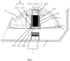
- the clothing treatment apparatus of the present disclosure includes a rotary part 4 and a stationary part 5, and the rotary part 4 is rotatably arranged in the stationary part 5; the clothing treatment apparatus further includes a magnet supply module 1, a magnet induction power generation module 2 and a light emitting lamp 3; the magnet induction power generation module 2 is fixed on the rotary part 4, and the magnet supply module 1 is fixed on the stationary part 5 at a position corresponding to that of the magnet induction power generation module 2; of course, the positions of the magnet induction power generation module 2 and the magnet supply module 1 can be reversed, as long as a relative movement between the two can be achieved to realize power generation, thus further supplying power for the light emitting lamp 3.
- the magnet supply module 1 includes a permanent magnet 11 and a third housing 12; the third housing 12 is fixed on an inner tub of the stationary part 5, and the permanent magnet 11 is fixed on the third housing 12, thus generating a lasting magnetic field.
- the magnet supply module 1 can also have only one permanent magnet 11, which is directly embedded and fixed on the inner tub of the stationary part 5.
- the magnet supply module 1 can also be an electromagnet; since the magnet supply module 1 is fixed on the stationary part 5, the stationary part 5 alone can be easily connected to the power supply, so the electromagnet is also feasible.
- the magnet induction power generation module 2 includes a first housing 21, a coil 23 and a magnetic conductor 24.
- the first housing 21 includes a barrel 211 and a barrel cover 212.
- the barrel 211 is fixed on a pulsator of the rotary part 4, the coil 23 is fixed on an inner side of the barrel 211, and the magnetic conductor 24 is fixed on an inner side of the coil 23 and is arranged corresponding to the magnet supply module 1; that is, when the pulsator rotates, the magnetic conductor 24 can enter and leave the magnetic field of the magnet supply module 1 and generate an induction magnetic field by itself.
- the barrel cover 212 encloses the coil 23 and the magnetic conductor 24 inside the barrel 211, and the light emitting lamp 3 is electrically connected with the coil 23 and fixed on the first housing 21.
- the magnetic conductor 24 can be an iron core; of course, it can also be other members or devices, as long as it is an object that can generate a varying magnetic field by itself as the permanent magnet 11 becomes close to or away from the magnetic conductor 24.
- the magnet induction power generation module 2 when the pulsator starts to rotate, the magnet induction power generation module 2 will also rotate therewith, whereas the permanent magnet 11 is fixed on the inner tub and cannot move. At this time, the magnet induction power generation module 2 will become close to the permanent magnet 11 once and away from the permanent magnet 11 once every time the pulsator rotates by one turn; correspondingly, the magnetic conductor 24 will increase its own magnetic field when it is close to the permanent magnet 11, and will decrease its own magnetic field when it is away from the permanent magnet 11. Each time the pulsator rotates by one turn, the magnetic conductor 24 will complete one time of change in the magnitude of the magnetic field. The constant change of the magnetic field will cause the magnetic lines of force to move relative to the coil 23, which realizes cutting of the magnetic lines of force by the coil 23, thus generating the current and lighting up the light emitting lamp 3.
- the advantage of the above arrangement is that it is simple and easy to implement, and it can realize the illumination inside the pulsator washing machine without providing a separate wiring, thus solving the problem of wiring for an external power supply.
- the design of the permanent magnet 11 and the magnetic conductor 24 elaborately solves the conduction between magnetic fields, making the overall structure simpler and more feasible.
- the split arrangement of the barrel 211 and the barrel cover 212 enables the operator to assemble very easily, and in the subsequent maintenance process, after the pulsator is removed, it is also very easy to replace the entirety of the combination of the barrel 211 and the barrel cover 212 by unscrewing or separately replace damaged parts such as the coil 23 and the magnetic conductor 24 in the barrel 211, thus reducing the subsequent maintenance cost.
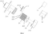
- the magnet induction power generation module 2 further includes a second housing 22, which is fixed on the inner side of the barrel 211; the coil 23 is wound on an outer side of the second housing 22, the magnetic conductor 24 is fixed on an inner side of the second housing 22, and the barrel cover 212 seals the second housing 22 in the barrel 211.
- the barrel cover 212 is snap-fit with the second housing 22, and the barrel cover 212 is connected with the barrel 211 through threads.
- the second housing 22 includes a winding part 221, a hollow hole 222 and a lampstand 223.
- the coil 23 is wound on the winding part 221, the magnetic conductor 24 is arranged in the hollow hole 222, and the light emitting lamp 3 is arranged in the lampstand 223.
- the barrel 211 is provided with a light output hole 2111, and the inner side of the barrel 211 is further provided with a transparent glass 2112.
- the transparent glass 2112 covers the light output hole 2111, and a top end of the lampstand 223 abuts against the transparent glass 2112.
- the transparent glass 2112 can be quartz glass, transparent plastic glass or other glass that is advantageous for light transmission and has a sufficient strength, as long as it can ensure smooth passage of light.
- the second housing 22 is arranged to have the light emitting lamp 3, the coil 23 and the magnetic conductor 24 all integrated thereon; then the second housing 22 is snap-fit on the barrel cover 212 (of course, it can also be connected through other conventional connection means such as thread), and the barrel cover 212 and the connected second housing 22 are inserted together into the barrel 211 before being connected and fixed by threads, which will make the roles of the barrel 211, the barrel cover 212 and the second housing 22 completely independent and separate from each other.
- the barrel 211 and the barrel cover 212 are only responsible for the overall fixation and waterproofing.
- the second housing 22 has the light emitting lamp 3, the coil 23 and the magnetic conductor 24 integrated thereon, which can be completely independently subcontracted to different manufacturers in the early processing stage.
- the overall removal and replacement of the internal parts can also be easily completed, and there is no need to replace the external barrel 211 and barrel cover 212.
- a waterproof structure such as a sealing ring, can still be arranged between the second housing 22 and the barrel 211 to achieve multi-layer waterproof, so that the overall structure has better waterproof performance and longer service life.
- the barrel 211 and the barrel cover 212 are designed to be waterproof, the internal structure is designed to be easily disassembled and assembled, and the second housing 22 is designed to be able to integrate all of the coil 23, the magnetic conductor 24 and the light emitting lamp 3 together to realize the overall insertion and removal into/from the barrel 211, making their maintenance steps as convenient as the daily removal of household bulbs. Due to the high integration of the internal structure, the combined parts of the second housing 22 with the coil 23, the magnetic conductor 24 and the light emitting lamp 3 can also achieve the unification of the inner core. It is only necessary to adjust the barrel 211 and the barrel cover 212 according to different structure models of the washing machine to achieve the universality of the internal power generation structure, and the internal structures subsequently provided for the market can be unified, which can achieve great cost reduction.
- the light emitting lamp 3 can be an illumination lamp such as an LED lamp, or an ultraviolet sterilization lamp for sterilization purpose, or a combination of the two for function switching, or other functional lamps, such as a mosquito killing lamp, all of which do not deviate from the principle of the present disclosure, and therefore will fall within the scope of protection of the present disclosure.
- an illumination lamp such as an LED lamp, or an ultraviolet sterilization lamp for sterilization purpose, or a combination of the two for function switching, or other functional lamps, such as a mosquito killing lamp, all of which do not deviate from the principle of the present disclosure, and therefore will fall within the scope of protection of the present disclosure.
- the positions for fixing the light emitting lamp 3 are various.
- the light emitting lamp 3 can be fixed on either of the first housing 21, the second housing 22 or the pulsator.
- the magnet induction power generation module 2 is arranged on the inner tub, the magnet supply module 1 will be arranged on the pulsator; at this time, the light emitting lamp 3 can also be arranged on the inner tub of the stationary part 5.
- magnet induction power generation module 2 and one magnet supply module 1 are shown exemplarily in FIG. 1 , it is obvious that the numbers of the two can be set at will, and they do not have to be set with the numbers thereof corresponding to each other.
- three magnet supply modules 1 can be arranged at a bottom of the inner tub in a circular path, but five magnet induction power generation modules 2 can be arranged on the pulsator. As the pulsator rotates, it is obvious that the magnet induction power generation modules 2 can still generate electricity to light up the light emitting lamp 3. These do not deviate from the principle of the present disclosure, so they will fall within the scope of protection of the present disclosure.
- the clothing treatment apparatus of the present disclosure can obviously be other apparatuses.
- it can also be a drum washing machine, etc.;
- the rotary part 4 is an inner cylinder, and the stationary part 5 is an outer cylinder;
- the fixing method thereof is also similar to the pulsator washing machine, and the principle is the same, so a repeated description will be omitted herein.
- the innovation of the present disclosure further lies in that when facing such problems, the first condition for those skilled in the art is to arrange a wire on the periphery of the rotary part 4.
- the wire is arranged near the periphery of the rotary part 4, there will be more wires passing to the vicinity of the rotary part 4 through an operation panel; especially for the drum washing machine, these wires are usually clamped on the long-term stationary housing or outer cylinder on the outer side the rotary part 4 through buckles.
- Such a method has no significant influence in a short term.
- the washing machine is an electronic product for long term use and has a long service life, circuit safety and quality problems thereof cannot be ignored.
- This method does not need wiring on the outer side of the rotary part 4, thus solving the problem that more wires are easily rolled into the rotary part 4, saving electric energy, and also avoiding the problem that the electrical connection between the rotating drum and the stationary external power supply is difficult, which provides a new direction for solving the problem of internal illumination of the washing machine.
Landscapes
- Engineering & Computer Science (AREA)
- Textile Engineering (AREA)
- General Engineering & Computer Science (AREA)
- Health & Medical Sciences (AREA)
- Power Engineering (AREA)
- Epidemiology (AREA)
- General Health & Medical Sciences (AREA)
- Public Health (AREA)
- Veterinary Medicine (AREA)
- Animal Behavior & Ethology (AREA)
- Life Sciences & Earth Sciences (AREA)
- Accessory Of Washing/Drying Machine, Commercial Washing/Drying Machine, Other Washing/Drying Machine (AREA)
- Detail Structures Of Washing Machines And Dryers (AREA)
Abstract
Description
- The present disclosure belongs to the technical field of clothing treatment apparatus, and specifically provides a clothing treatment apparatus.
- In the process of washing clothing by a washing machine, if an outdoor environment is dark, for example, when the washing machine is arranged in a corner with insufficient light, it is very difficult for the operator to see a washing condition of the clothing inside the washing machine. Especially for some special clothing, such as woolen sweater, the material of the clothing itself is fragile and cannot withstand a large beating force. In the washing process of the clothing, the operator often wants to see clearly the specific washing status of the clothing inside the washing machine so as to adjust washing parameters, thus enabling the washing machine to adapt to the washing of different clothing.
- In the prior art, since an interior of the washing machine is rotating, it is very difficult to install an electric lamp on an inner cylinder, and it is also necessary to separately arrange an external power supply for the light emitting lamp. In view of this, the washing machines in the prior art are usually not provided with a light source in the cylinder. It is not that those skilled in the art do not want to set it, but it is because arranging the external power supply separately for the light emitting lamp is too difficult, and the cost is too high.
- At present, an electric brush can be selected in the prior art to realize the transmission of electric energy between a moving object and a stationary object. However, due to the large amount of water inside the washing machine itself, the possibility of electric leakage will be greatly increased when using the electric brush for transmission. Obviously, it is not feasible to use the electric brush for transmission on the washing machine, which is a device that attaches great importance to safety. The most advanced technologies include those similar to wireless charging technology, but such technologies need a built-in rechargeable battery, and the overall cost is expensive. In the event of cost control, it is obviously also not suitable to direct apply such technologies to the field of washing machine for illumination.
- Accordingly, there is a need for a new clothing treatment apparatus in the art to solve the problem that it is difficult to arrange an external power supply due to internal rotation of the existing clothing treatment apparatuses.
- In order to solve the above problem in the prior art, that is, to solve the problem that it is difficult to arrange an external power supply due to internal rotation of the existing clothing treatment apparatuses, the present disclosure provides a clothing treatment apparatus, which includes a rotary part and a stationary part, and the rotary part is rotatably arranged in the stationary part, wherein the clothing treatment apparatus further includes a magnet supply module, a magnet induction power generation module and a light emitting lamp;
- the magnet induction power generation module is fixed on one of the rotary part or the stationary part, and the magnet supply module is fixed on the other of the rotary part or the stationary part at a position corresponding to that of the magnet induction power generation module;
- the magnet induction power generation module includes a first housing, a coil and a magnetic conductor; the first housing includes a barrel and a barrel cover, the barrel is fixed on the rotary part or the stationary part, and the coil is fixed on an inner side of the barrel; the magnetic conductor is fixed on an inner side of the coil and is arranged corresponding to the magnet supply module, and the barrel cover encloses the coil and the magnetic conductor inside the barrel; and
- the light emitting lamp is electrically connected with the coil and is fixed on the first housing, or fixed on the rotary part or the stationary part together with the magnet induction power generation module; the magnet supply module generates a magnetic field, and when the rotary part rotates relative to the stationary part, the magnet induction power generation module and the magnet supply module reciprocate in a path close to or away from each other, thus generating electric energy internally, and further supplying power for the light emitting lamp.
- In a preferred technical solution of the above clothing treatment apparatus, the magnetic induction power generation module further includes a second housing, which is fixed on the inner side of the barrel; the coil is wound on an outer side of the second housing, the magnetic conductor is fixed on an inner side of the second housing, and the barrel cover seals the second housing in the barrel.
- In a preferred technical solution of the above clothing treatment apparatus, the barrel cover and the barrel are connected by threads; and/or the barrel cover is snap-fit with the second housing.
- In a preferred technical solution of the above clothing treatment apparatus, the second housing includes a winding part, a hollow hole and a lampstand; the coil is wound on the winding part, the magnetic conductor is arranged in the hollow hole, and the light emitting lamp is arranged in the lampstand.
- In a preferred technical solution of the above clothing treatment apparatus, the barrel is provided with a light output hole, and the inner side of the barrel is further provided with a transparent glass; the transparent glass covers the light output hole, and a top end of the lampstand abuts against the transparent glass.
- In a preferred technical solution of the above clothing treatment apparatus, the magnetic conductor is an iron core.
- In a preferred technical solution of the above clothing treatment apparatus, the magnet supply module includes a permanent magnet.
- In a preferred technical solution of the above clothing treatment apparatus, the magnet supply module further includes a third housing, and the permanent magnet is fixed inside the third housing.
- In a preferred technical solution of the above clothing treatment apparatus, the magnet supply module and/or the magnet induction power generation module are each provided in plural; and/or the light emitting lamp is an ultraviolet sterilization lamp or an LED illumination lamp.
- In a preferred technical solution of the above clothing treatment apparatus, the clothing treatment apparatus is a pulsator washing machine; correspondingly, the rotary part is a pulsator, and the stationary part is an inner tub; and/or the clothing treatment apparatus is a drum washing machine; correspondingly, the rotary part is an inner cylinder, and the stationary part is an outer cylinder.
- It can be understood by those in the art that in the technical solutions of the present disclosure, the clothing treatment apparatus includes a rotary part and a stationary part, and the rotary part is rotatably arranged in the stationary part; the clothing treatment apparatus further includes a magnet supply module, a magnet induction power generation module and a light emitting lamp; the magnet induction power generation module is fixed on one of the rotary part or the stationary part, and the magnet supply module is fixed on the other of the rotary part or the stationary part at a position corresponding to that of the magnet induction power generation module; the magnet induction power generation module includes a first housing, a coil and a magnetic conductor; the first housing includes a barrel and a barrel cover, the barrel is fixed on the rotary part or the stationary part, and the coil is fixed on an inner side of the barrel; the magnetic conductor is fixed on an inner side of the coil and is arranged corresponding to the magnet supply module, and the barrel cover encloses the coil and the magnetic conductor inside the barrel; the light emitting lamp is electrically connected with the coil and is fixed on the first housing, or fixed on the rotary part or the stationary part together with the magnet induction power generation module; the magnet supply module generates a magnetic field, and when the rotary part rotates relative to the stationary part, the magnet induction power generation module and the magnet supply module reciprocate in a path close to or away from each other, thus generating electric energy internally, and further supplying power for the light emitting lamp.
- Through the above arrangement, the clothing treatment apparatus of the present disclosure can generate electric energy through the relative movement of the magnet supply module and the magnet induction power generation module, so that the light emitting lamp lights up. The clothing treatment apparatus of the present disclosure does not need an external power supply, and it only makes the magnetic field be close to and away from the magnetic conductor so that the magnetic conductor generates a varying magnetic field; thus, the fixed coil can also cut magnetic lines of force to generate electric energy, so that it is unnecessary to connect a power supply into the interior, and thus there will be no electric wires near the rotary part, thus solving the problem that it is difficult for the clothing treatment apparatus to separately arrange an external power supply for the light emitting lamp.
- The clothing treatment apparatus of the present disclosure will be described below with reference to the accompanying drawings and in connection with a pulsator washing machine. In the drawings:
-
FIG. 1 is a schematic view showing an internal structure between a pulsator and an inner tub of a pulsator washing machine; -
FIG. 2 is a schematic view showing the position of a magnet induction power generation module installed on the pulsator; -
FIG. 3 is an exploded view of the magnet induction power generation module and a magnet supply module; and -
FIG. 4 shows the magnet induction power generation module and the magnet supply module after completion of assembly. - 1: magnet supply module; 11: permanent magnet; 12: third housing; 2: magnet induction power generation module; 21: first housing; 211: barrel; 2111: light output hole; 2112: transparent glass; 212: barrel cover; 22: second housing; 221: winding part; 222: hollow hole; 223: lampstand; 23: coil; 24: magnetic conductor; 3: light emitting lamp; 4: rotary part; 5: stationary part.
- Preferred embodiments of the present disclosure will be described below with reference to the accompanying drawings. It should be understood by those skilled in the art that these embodiments are only used to explain the technical principle of the present disclosure, and are not intended to limit the scope of protection of the present disclosure. Those skilled in the art can make adjustments thereto as required so as to adapt to specific application scenes. For example, although an illumination lamp is used as an example of the light emitting lamp in the specification for description, obviously, the light emitting lamp of the present disclosure can also be other functional lamps such as an ultraviolet sterilization lamp or a mosquito killing lamp, so as to meet other needs of users.
- It should be noted that in the description of the present disclosure, terms indicating directional or positional relationships, such as "center", "above", "below", "left", "right", "vertical", "horizontal", "inner", "outer" and the like, are based on the directional or positional relationships shown in the accompanying drawings. They are only used for ease of description, and do not indicate or imply that the device or element must have a specific orientation, or be constructed or operated in a specific orientation; therefore, they should not be considered as limitations to the present disclosure. In addition, terms "first", "second" and "third" are only used for descriptive purposes, and should not be interpreted as indicating or implying relative importance.
- In addition, it should also be noted that in the description of the present disclosure, unless otherwise clearly specified and defined, terms "install", "connect" and "connection" should be understood in a broad sense; for example, the connection may be a fixed connection, or may also be a detachable connection, or an integral connection; it may be a mechanical connection, or an electrical connection; it may be a direct connection, or an indirect connection implemented through an intermediate medium, or it may be internal communication between two elements. For those skilled in the art, the specific meaning of the above terms in the present disclosure can be interpreted according to specific situations.
- Referring to
FIGS. 1 to 4 , in order to solve the problem that it is difficult for the existing clothing treatment apparatuses to separately arrange an external power supply for the light emitting lamp, in a possible embodiment, the clothing treatment apparatus of the present disclosure includes arotary part 4 and astationary part 5, and therotary part 4 is rotatably arranged in thestationary part 5; the clothing treatment apparatus further includes a magnet supply module 1, a magnet inductionpower generation module 2 and alight emitting lamp 3; the magnet inductionpower generation module 2 is fixed on therotary part 4, and the magnet supply module 1 is fixed on thestationary part 5 at a position corresponding to that of the magnet inductionpower generation module 2; of course, the positions of the magnet inductionpower generation module 2 and the magnet supply module 1 can be reversed, as long as a relative movement between the two can be achieved to realize power generation, thus further supplying power for thelight emitting lamp 3. - As shown in
FIGS. 1 and3 , the magnet supply module 1 includes apermanent magnet 11 and athird housing 12; thethird housing 12 is fixed on an inner tub of thestationary part 5, and thepermanent magnet 11 is fixed on thethird housing 12, thus generating a lasting magnetic field. Of course, the magnet supply module 1 can also have only onepermanent magnet 11, which is directly embedded and fixed on the inner tub of thestationary part 5. Alternatively, the magnet supply module 1 can also be an electromagnet; since the magnet supply module 1 is fixed on thestationary part 5, thestationary part 5 alone can be easily connected to the power supply, so the electromagnet is also feasible. - Referring further to
FIGS. 1 and3 , the magnet inductionpower generation module 2 includes afirst housing 21, acoil 23 and amagnetic conductor 24. Thefirst housing 21 includes abarrel 211 and abarrel cover 212. Thebarrel 211 is fixed on a pulsator of therotary part 4, thecoil 23 is fixed on an inner side of thebarrel 211, and themagnetic conductor 24 is fixed on an inner side of thecoil 23 and is arranged corresponding to the magnet supply module 1; that is, when the pulsator rotates, themagnetic conductor 24 can enter and leave the magnetic field of the magnet supply module 1 and generate an induction magnetic field by itself. Thebarrel cover 212 encloses thecoil 23 and themagnetic conductor 24 inside thebarrel 211, and thelight emitting lamp 3 is electrically connected with thecoil 23 and fixed on thefirst housing 21. Themagnetic conductor 24 can be an iron core; of course, it can also be other members or devices, as long as it is an object that can generate a varying magnetic field by itself as thepermanent magnet 11 becomes close to or away from themagnetic conductor 24. - The overall working process is described as follows: when the pulsator starts to rotate, the magnet induction
power generation module 2 will also rotate therewith, whereas thepermanent magnet 11 is fixed on the inner tub and cannot move. At this time, the magnet inductionpower generation module 2 will become close to thepermanent magnet 11 once and away from thepermanent magnet 11 once every time the pulsator rotates by one turn; correspondingly, themagnetic conductor 24 will increase its own magnetic field when it is close to thepermanent magnet 11, and will decrease its own magnetic field when it is away from thepermanent magnet 11. Each time the pulsator rotates by one turn, themagnetic conductor 24 will complete one time of change in the magnitude of the magnetic field. The constant change of the magnetic field will cause the magnetic lines of force to move relative to thecoil 23, which realizes cutting of the magnetic lines of force by thecoil 23, thus generating the current and lighting up thelight emitting lamp 3. - The advantage of the above arrangement is that it is simple and easy to implement, and it can realize the illumination inside the pulsator washing machine without providing a separate wiring, thus solving the problem of wiring for an external power supply. The design of the
permanent magnet 11 and themagnetic conductor 24 elaborately solves the conduction between magnetic fields, making the overall structure simpler and more feasible. The split arrangement of thebarrel 211 and thebarrel cover 212 enables the operator to assemble very easily, and in the subsequent maintenance process, after the pulsator is removed, it is also very easy to replace the entirety of the combination of thebarrel 211 and thebarrel cover 212 by unscrewing or separately replace damaged parts such as thecoil 23 and themagnetic conductor 24 in thebarrel 211, thus reducing the subsequent maintenance cost. Moreover, according to the design of thebarrel 211 and thebarrel cover 212 of the present disclosure, convenient installation can be realized by only adding a few threaded holes on the basis of the original pulsator structure design. There is no major change in the overall structure of the washing machine, which makes the clothing treatment apparatus of the present disclosure compatible with the original production line in the production process without making major changes. Since there is very little modification to the original structure, an optional installation can be provided to the users to achieve price classification, thus enabling the users to have more choices. - With continued reference to
FIGS. 1 and3 below, in another possible embodiment, the magnet inductionpower generation module 2 further includes asecond housing 22, which is fixed on the inner side of thebarrel 211; thecoil 23 is wound on an outer side of thesecond housing 22, themagnetic conductor 24 is fixed on an inner side of thesecond housing 22, and the barrel cover 212 seals thesecond housing 22 in thebarrel 211. Thebarrel cover 212 is snap-fit with thesecond housing 22, and thebarrel cover 212 is connected with thebarrel 211 through threads. Thesecond housing 22 includes a windingpart 221, ahollow hole 222 and alampstand 223. Thecoil 23 is wound on the windingpart 221, themagnetic conductor 24 is arranged in thehollow hole 222, and thelight emitting lamp 3 is arranged in thelampstand 223. Thebarrel 211 is provided with alight output hole 2111, and the inner side of thebarrel 211 is further provided with atransparent glass 2112. Thetransparent glass 2112 covers thelight output hole 2111, and a top end of thelampstand 223 abuts against thetransparent glass 2112. Thetransparent glass 2112 can be quartz glass, transparent plastic glass or other glass that is advantageous for light transmission and has a sufficient strength, as long as it can ensure smooth passage of light. - The above arrangement has the following advantage: the
second housing 22 is arranged to have thelight emitting lamp 3, thecoil 23 and themagnetic conductor 24 all integrated thereon; then thesecond housing 22 is snap-fit on the barrel cover 212 (of course, it can also be connected through other conventional connection means such as thread), and thebarrel cover 212 and the connectedsecond housing 22 are inserted together into thebarrel 211 before being connected and fixed by threads, which will make the roles of thebarrel 211, thebarrel cover 212 and thesecond housing 22 completely independent and separate from each other. Thebarrel 211 and thebarrel cover 212 are only responsible for the overall fixation and waterproofing. Thesecond housing 22 has thelight emitting lamp 3, thecoil 23 and themagnetic conductor 24 integrated thereon, which can be completely independently subcontracted to different manufacturers in the early processing stage. In the subsequent maintenance stage, if it is only the internal parts such as thelight emitting lamp 3 that are damaged, the overall removal and replacement of the internal parts can also be easily completed, and there is no need to replace theexternal barrel 211 andbarrel cover 212. At the same time, since thesecond housing 22 is inserted into thebarrel 211, a waterproof structure, such as a sealing ring, can still be arranged between thesecond housing 22 and thebarrel 211 to achieve multi-layer waterproof, so that the overall structure has better waterproof performance and longer service life. - To sum up, due to the relative movement of the
rotary part 4 and thestationary part 5, wiring is difficult in the prior art, whereas the present disclosure elaborately takes advantage of the relative movement of therotary part 4 and thestationary part 5 and the change of magnetic field caused by the conduction of the magnet, so that thecoil 23 in the magnet inductionpower generation module 2 can cut the magnetic lines of force to realize power generation and supply power for the light emitting lamp, which elaborately converts the obstruction into a power source and dispenses with the need for wiring. In addition, in order to save processing cost and later maintenance cost and rationalize the structure layout, thebarrel 211 and thebarrel cover 212 are designed to be waterproof, the internal structure is designed to be easily disassembled and assembled, and thesecond housing 22 is designed to be able to integrate all of thecoil 23, themagnetic conductor 24 and thelight emitting lamp 3 together to realize the overall insertion and removal into/from thebarrel 211, making their maintenance steps as convenient as the daily removal of household bulbs. Due to the high integration of the internal structure, the combined parts of thesecond housing 22 with thecoil 23, themagnetic conductor 24 and thelight emitting lamp 3 can also achieve the unification of the inner core. It is only necessary to adjust thebarrel 211 and thebarrel cover 212 according to different structure models of the washing machine to achieve the universality of the internal power generation structure, and the internal structures subsequently provided for the market can be unified, which can achieve great cost reduction. - It should be noted that the above embodiments are only used to illustrate the principle of the present disclosure and are not intended to limit the scope of protection of the present disclosure. Without departing from the principle of the present disclosure, those skilled in the art can adjust the above structure so that the present disclosure can be applied to more specific application scenes.
- For example, in an alternative embodiment, the
light emitting lamp 3 can be an illumination lamp such as an LED lamp, or an ultraviolet sterilization lamp for sterilization purpose, or a combination of the two for function switching, or other functional lamps, such as a mosquito killing lamp, all of which do not deviate from the principle of the present disclosure, and therefore will fall within the scope of protection of the present disclosure. - For example, in another alternative embodiment, the positions for fixing the
light emitting lamp 3 are various. For example, when the specific embodiment is the structure inFIG. 1 , thelight emitting lamp 3 can be fixed on either of thefirst housing 21, thesecond housing 22 or the pulsator. Correspondingly, if the magnet inductionpower generation module 2 is arranged on the inner tub, the magnet supply module 1 will be arranged on the pulsator; at this time, thelight emitting lamp 3 can also be arranged on the inner tub of thestationary part 5. Those skilled in the art can select suitable installation positions according to actual needs, all of which do not deviate from the principle of the present disclosure, and therefore fall within the scope of protection of the present disclosure. - For example, in another alternative embodiment, although only one magnet induction
power generation module 2 and one magnet supply module 1 are shown exemplarily inFIG. 1 , it is obvious that the numbers of the two can be set at will, and they do not have to be set with the numbers thereof corresponding to each other. For example, three magnet supply modules 1 can be arranged at a bottom of the inner tub in a circular path, but five magnet inductionpower generation modules 2 can be arranged on the pulsator. As the pulsator rotates, it is obvious that the magnet inductionpower generation modules 2 can still generate electricity to light up thelight emitting lamp 3. These do not deviate from the principle of the present disclosure, so they will fall within the scope of protection of the present disclosure. - Finally, it should be noted that although the present disclosure is described by taking a pulsator washing machine as an example, the clothing treatment apparatus of the present disclosure can obviously be other apparatuses. For example, it can also be a drum washing machine, etc.; correspondingly, the
rotary part 4 is an inner cylinder, and thestationary part 5 is an outer cylinder; the fixing method thereof is also similar to the pulsator washing machine, and the principle is the same, so a repeated description will be omitted herein. - It should be noted that the innovation of the present disclosure further lies in that when facing such problems, the first condition for those skilled in the art is to arrange a wire on the periphery of the
rotary part 4. However, as long as the wire is arranged near the periphery of therotary part 4, there will be more wires passing to the vicinity of therotary part 4 through an operation panel; especially for the drum washing machine, these wires are usually clamped on the long-term stationary housing or outer cylinder on the outer side therotary part 4 through buckles. Such a method has no significant influence in a short term. However, since the washing machine is an electronic product for long term use and has a long service life, circuit safety and quality problems thereof cannot be ignored. Under long-term vibration conditions, the buckles usually fall off, which makes it impossible for the wires to fully fit the outer side any longer. Once the wires are rolled into rotation by therotary part 4, they will cause serious electric leakage accidents and even fire. In view of this, although it is very necessary to illuminate therotary part 4 of the drum washing machine, for safety reasons, those skilled in the art have not yet developed a wiring method with high safety performance to solve this problem. In view of the facts that thelight emitting lamp 3 itself does not need much electric energy to maintain its brightness, and that the more wires arranged outside therotary part 4, the higher the risk, the inventor creatively proposed the above solution to solve the power supply problem of thelight emitting lamp 3. After many tests, the inventor found that the electric energy generated by cutting the magnetic lines of force by thecoil 23 is enough to maintain the illumination of thelight emitting lamp 3. This method does not need wiring on the outer side of therotary part 4, thus solving the problem that more wires are easily rolled into therotary part 4, saving electric energy, and also avoiding the problem that the electrical connection between the rotating drum and the stationary external power supply is difficult, which provides a new direction for solving the problem of internal illumination of the washing machine. - Hitherto, the technical solutions of the present disclosure have been described in connection with the preferred embodiments shown in the accompanying drawings, but it is easily understood by those skilled in the art that the scope of protection of the present disclosure is obviously not limited to these specific embodiments. Without departing from the principles of the present disclosure, those skilled in the art can make equivalent changes or replacements to relevant technical features, and all the technical solutions after these changes or replacements will fall within the scope of protection of the present disclosure.
Claims (10)
- A clothing treatment apparatus, comprising a rotary part and a stationary part, the rotary part being rotatably arranged in the stationary part, wherein the clothing treatment apparatus further comprises a magnet supply module, a magnet induction power generation module and a light emitting lamp;the magnet induction power generation module is fixed on one of the rotary part or the stationary part, and the magnet supply module is fixed on the other of the rotary part or the stationary part at a position corresponding to that of the magnet induction power generation module;the magnet induction power generation module comprises a first housing, a coil and a magnetic conductor; the first housing comprises a barrel and a barrel cover, the barrel is fixed on the rotary part or the stationary part, and the coil is fixed on an inner side of the barrel; the magnetic conductor is fixed on an inner side of the coil and is arranged corresponding to the magnet supply module, and the barrel cover encloses the coil and the magnetic conductor inside the barrel;the light emitting lamp is electrically connected with the coil and is fixed on the first housing, or fixed on the rotary part or the stationary part together with the magnet induction power generation module; andthe magnet supply module generates a magnetic field, and when the rotary part rotates relative to the stationary part, the magnet induction power generation module and the magnet supply module reciprocate in a path close to or away from each other, thus generating electric energy internally, and further supplying power for the light emitting lamp.
- The clothing treatment apparatus according to claim 1, wherein the magnetic induction power generation module further comprises a second housing, which is fixed on the inner side of the barrel; the coil is wound on an outer side of the second housing, the magnetic conductor is fixed on an inner side of the second housing, and the barrel cover seals the second housing in the barrel.
- The clothing treatment apparatus according to claim 2, wherein the barrel cover and the barrel are connected by threads; and/or
the barrel cover is snap-fit with the second housing. - The clothing treatment apparatus according to claim 2, wherein the second housing comprises a winding part, a hollow hole and a lampstand; the coil is wound on the winding part, the magnetic conductor is arranged in the hollow hole, and the light emitting lamp is arranged in the lampstand.
- The clothing treatment apparatus according to claim 4, wherein the barrel is provided with a light output hole, and the inner side of the barrel is further provided with a transparent glass; the transparent glass covers the light output hole, and a top end of the lampstand abuts against the transparent glass.
- The clothing treatment apparatus according to claim 1, wherein the magnetic conductor is an iron core.
- The clothing treatment apparatus according to claim 1, wherein the magnet supply module comprises a permanent magnet.
- The clothing treatment apparatus according to claim 7, wherein the magnet supply module further comprises a third housing, and the permanent magnet is fixed inside the third housing.
- The clothing treatment apparatus according to claim 1, wherein the magnet supply module and/or the magnet induction power generation module are each provided in plural; and/or
the light emitting lamp is an ultraviolet sterilization lamp or an LED illumination lamp. - The clothing treatment apparatus according to claim 1, wherein the clothing treatment apparatus is a pulsator washing machine; correspondingly, the rotary part is a pulsator, and the stationary part is an inner tub; and/or
the clothing treatment apparatus is a drum washing machine; correspondingly, the rotary part is an inner cylinder, and the stationary part is an outer cylinder.
Applications Claiming Priority (2)
| Application Number | Priority Date | Filing Date | Title |
|---|---|---|---|
| CN202010898189.6A CN112080901B (en) | 2020-08-31 | 2020-08-31 | Laundry treatment equipment |
| PCT/CN2021/105400 WO2022042075A1 (en) | 2020-08-31 | 2021-07-09 | Clothing treatment device |
Publications (4)
| Publication Number | Publication Date |
|---|---|
| EP4190959A1 true EP4190959A1 (en) | 2023-06-07 |
| EP4190959A4 EP4190959A4 (en) | 2023-09-06 |
| EP4190959B1 EP4190959B1 (en) | 2025-12-31 |
| EP4190959C0 EP4190959C0 (en) | 2025-12-31 |
Family
ID=73731776
Family Applications (1)
| Application Number | Title | Priority Date | Filing Date |
|---|---|---|---|
| EP21859915.7A Active EP4190959B1 (en) | 2020-08-31 | 2021-07-09 | CLOTHING TREATMENT DEVICE |
Country Status (3)
| Country | Link |
|---|---|
| EP (1) | EP4190959B1 (en) |
| CN (1) | CN112080901B (en) |
| WO (1) | WO2022042075A1 (en) |
Cited By (1)
| Publication number | Priority date | Publication date | Assignee | Title |
|---|---|---|---|---|
| US12002104B2 (en) | 2013-03-10 | 2024-06-04 | State Farm Mutual Automobile Insurance Company | Dynamic auto insurance policy quote creation based on tracked user data |
Families Citing this family (6)
| Publication number | Priority date | Publication date | Assignee | Title |
|---|---|---|---|---|
| CN113089267A (en) * | 2019-12-23 | 2021-07-09 | 青岛海尔洗衣机有限公司 | Clothes treating apparatus |
| CN113417117B (en) * | 2020-03-03 | 2023-08-04 | 青岛海尔洗衣机有限公司 | Clothes treating apparatus |
| CN113389015B (en) * | 2020-03-12 | 2023-05-12 | 青岛海尔洗衣机有限公司 | Clothes treating apparatus |
| CN113550124B (en) * | 2020-04-03 | 2023-10-10 | 天津海尔洗涤电器有限公司 | Laundry treatment equipment |
| CN112080901B (en) * | 2020-08-31 | 2024-02-13 | 青岛海尔洗衣机有限公司 | Laundry treatment equipment |
| CN115341355A (en) * | 2021-05-14 | 2022-11-15 | 青岛海尔滚筒洗衣机有限公司 | Washing machine |
Family Cites Families (10)
| Publication number | Priority date | Publication date | Assignee | Title |
|---|---|---|---|---|
| EP2604740B1 (en) * | 2011-12-16 | 2015-12-16 | Electrolux Home Products Corporation N.V. | Laundry machine with lighting apparatus for drum lighting |
| CN106012406B (en) * | 2016-07-08 | 2019-01-18 | 中山东菱威力电器有限公司 | A kind of washing machine having ultraviolet radiation for sterilizing and disinfecting function |
| CN206739072U (en) * | 2017-05-22 | 2017-12-12 | 陈亮 | Radio-frequency lamp |
| KR20200092043A (en) * | 2019-01-24 | 2020-08-03 | 엘지이노텍 주식회사 | Apparatus for sterilization |
| CN211112730U (en) * | 2019-08-02 | 2020-07-28 | 青岛海尔洗衣机有限公司 | Drum washing machine |
| CN211112754U (en) * | 2019-08-02 | 2020-07-28 | 青岛海尔洗衣机有限公司 | laundry treatment equipment |
| CN113417117B (en) * | 2020-03-03 | 2023-08-04 | 青岛海尔洗衣机有限公司 | Clothes treating apparatus |
| CN212247526U (en) * | 2020-04-10 | 2020-12-29 | 湖北开特汽车电子电器系统股份有限公司 | Sterilizing wave wheel disc of washing machine |
| CN113930944A (en) * | 2020-06-29 | 2022-01-14 | 青岛海尔洗衣机有限公司 | Washing machine |
| CN112080901B (en) * | 2020-08-31 | 2024-02-13 | 青岛海尔洗衣机有限公司 | Laundry treatment equipment |
-
2020
- 2020-08-31 CN CN202010898189.6A patent/CN112080901B/en active Active
-
2021
- 2021-07-09 WO PCT/CN2021/105400 patent/WO2022042075A1/en not_active Ceased
- 2021-07-09 EP EP21859915.7A patent/EP4190959B1/en active Active
Cited By (1)
| Publication number | Priority date | Publication date | Assignee | Title |
|---|---|---|---|---|
| US12002104B2 (en) | 2013-03-10 | 2024-06-04 | State Farm Mutual Automobile Insurance Company | Dynamic auto insurance policy quote creation based on tracked user data |
Also Published As
| Publication number | Publication date |
|---|---|
| EP4190959B1 (en) | 2025-12-31 |
| CN112080901B (en) | 2024-02-13 |
| CN112080901A (en) | 2020-12-15 |
| EP4190959C0 (en) | 2025-12-31 |
| EP4190959A4 (en) | 2023-09-06 |
| WO2022042075A1 (en) | 2022-03-03 |
Similar Documents
| Publication | Publication Date | Title |
|---|---|---|
| EP4190959B1 (en) | CLOTHING TREATMENT DEVICE | |
| CN211112730U (en) | Drum washing machine | |
| CN211395032U (en) | laundry treatment equipment | |
| CN211112754U (en) | laundry treatment equipment | |
| CN112391785A (en) | Drum washing machine | |
| CN105916264A (en) | LED ground embedded lamp and circuit thereof | |
| CN206708847U (en) | A kind of LED with rotating monitoring function | |
| CN211395033U (en) | laundry treatment equipment | |
| CN211395006U (en) | drum washing machine | |
| CN112709051A (en) | Clothes treating apparatus | |
| CN113493998B (en) | Clothes processing equipment | |
| CN113417117B (en) | Clothes treating apparatus | |
| CN113389015B (en) | Clothes treating apparatus | |
| KR101914335B1 (en) | Waterproof lamp of open form | |
| CN112709050A (en) | Clothes treating apparatus | |
| CN113550124B (en) | Laundry treatment equipment | |
| CN113622156A (en) | drum washing machine | |
| CN112709039A (en) | Drum washing machine | |
| WO2021223613A1 (en) | Control method for washing machine | |
| CN103363402A (en) | Lighting device for anechoic chamber | |
| JP7474837B2 (en) | Clothes processing equipment | |
| CN207778101U (en) | A kind of lighting device | |
| WO2021143646A1 (en) | Clothing treatment device | |
| WO2020233448A1 (en) | Laundry treatment apparatus | |
| CN106016093B (en) | Waterproof barrel lamp |
Legal Events
| Date | Code | Title | Description |
|---|---|---|---|
| STAA | Information on the status of an ep patent application or granted ep patent |
Free format text: STATUS: THE INTERNATIONAL PUBLICATION HAS BEEN MADE |
|
| PUAI | Public reference made under article 153(3) epc to a published international application that has entered the european phase |
Free format text: ORIGINAL CODE: 0009012 |
|
| STAA | Information on the status of an ep patent application or granted ep patent |
Free format text: STATUS: REQUEST FOR EXAMINATION WAS MADE |
|
| 17P | Request for examination filed |
Effective date: 20230301 |
|
| AK | Designated contracting states |
Kind code of ref document: A1 Designated state(s): AL AT BE BG CH CY CZ DE DK EE ES FI FR GB GR HR HU IE IS IT LI LT LU LV MC MK MT NL NO PL PT RO RS SE SI SK SM TR |
|
| REG | Reference to a national code |
Ref country code: DE Ref legal event code: R079 Free format text: PREVIOUS MAIN CLASS: D06F0039000000 Ipc: A61L0002100000 Ref document number: 602021045675 Country of ref document: DE |
|
| RIC1 | Information provided on ipc code assigned before grant |
Ipc: D06F 23/04 20060101ALN20230720BHEP Ipc: D06F 39/00 20200101ALN20230720BHEP Ipc: D06F 37/12 20060101ALI20230720BHEP Ipc: D06F 17/10 20060101ALI20230720BHEP Ipc: F21V 33/00 20060101ALI20230720BHEP Ipc: H02K 35/02 20060101ALI20230720BHEP Ipc: A61L 2/10 20060101AFI20230720BHEP |
|
| A4 | Supplementary search report drawn up and despatched |
Effective date: 20230804 |
|
| DAV | Request for validation of the european patent (deleted) | ||
| DAX | Request for extension of the european patent (deleted) | ||
| GRAP | Despatch of communication of intention to grant a patent |
Free format text: ORIGINAL CODE: EPIDOSNIGR1 |
|
| STAA | Information on the status of an ep patent application or granted ep patent |
Free format text: STATUS: GRANT OF PATENT IS INTENDED |
|
| RIC1 | Information provided on ipc code assigned before grant |
Ipc: A61L 2/10 20060101AFI20250716BHEP Ipc: H02K 35/02 20060101ALI20250716BHEP Ipc: F21V 33/00 20060101ALI20250716BHEP Ipc: D06F 17/10 20060101ALI20250716BHEP Ipc: D06F 37/12 20060101ALI20250716BHEP Ipc: H02K 7/18 20060101ALI20250716BHEP Ipc: D06F 39/00 20200101ALN20250716BHEP Ipc: D06F 23/04 20060101ALN20250716BHEP |
|
| INTG | Intention to grant announced |
Effective date: 20250819 |
|
| GRAS | Grant fee paid |
Free format text: ORIGINAL CODE: EPIDOSNIGR3 |
|
| GRAA | (expected) grant |
Free format text: ORIGINAL CODE: 0009210 |
|
| STAA | Information on the status of an ep patent application or granted ep patent |
Free format text: STATUS: THE PATENT HAS BEEN GRANTED |
|
| AK | Designated contracting states |
Kind code of ref document: B1 Designated state(s): AL AT BE BG CH CY CZ DE DK EE ES FI FR GB GR HR HU IE IS IT LI LT LU LV MC MK MT NL NO PL PT RO RS SE SI SK SM TR |
|
| REG | Reference to a national code |
Ref country code: CH Ref legal event code: F10 Free format text: ST27 STATUS EVENT CODE: U-0-0-F10-F00 (AS PROVIDED BY THE NATIONAL OFFICE) Effective date: 20251231 Ref country code: GB Ref legal event code: FG4D |
|
| REG | Reference to a national code |
Ref country code: DE Ref legal event code: R096 Ref document number: 602021045675 Country of ref document: DE |
|
| REG | Reference to a national code |
Ref country code: IE Ref legal event code: FG4D |
|
| U01 | Request for unitary effect filed |
Effective date: 20260115 |
|
| U07 | Unitary effect registered |
Designated state(s): AT BE BG DE DK EE FI FR IT LT LU LV MT NL PT RO SE SI Effective date: 20260126 |
|
| PG25 | Lapsed in a contracting state [announced via postgrant information from national office to epo] |
Ref country code: NO Free format text: LAPSE BECAUSE OF FAILURE TO SUBMIT A TRANSLATION OF THE DESCRIPTION OR TO PAY THE FEE WITHIN THE PRESCRIBED TIME-LIMIT Effective date: 20260331 |
|
| PG25 | Lapsed in a contracting state [announced via postgrant information from national office to epo] |
Ref country code: HR Free format text: LAPSE BECAUSE OF FAILURE TO SUBMIT A TRANSLATION OF THE DESCRIPTION OR TO PAY THE FEE WITHIN THE PRESCRIBED TIME-LIMIT Effective date: 20251231 |
|
| PG25 | Lapsed in a contracting state [announced via postgrant information from national office to epo] |
Ref country code: RS Free format text: LAPSE BECAUSE OF FAILURE TO SUBMIT A TRANSLATION OF THE DESCRIPTION OR TO PAY THE FEE WITHIN THE PRESCRIBED TIME-LIMIT Effective date: 20260331 |
|
| PG25 | Lapsed in a contracting state [announced via postgrant information from national office to epo] |
Ref country code: SM Free format text: LAPSE BECAUSE OF FAILURE TO SUBMIT A TRANSLATION OF THE DESCRIPTION OR TO PAY THE FEE WITHIN THE PRESCRIBED TIME-LIMIT Effective date: 20251231 |
|
| PG25 | Lapsed in a contracting state [announced via postgrant information from national office to epo] |
Ref country code: ES Free format text: LAPSE BECAUSE OF FAILURE TO SUBMIT A TRANSLATION OF THE DESCRIPTION OR TO PAY THE FEE WITHIN THE PRESCRIBED TIME-LIMIT Effective date: 20251231 |
|
| PG25 | Lapsed in a contracting state [announced via postgrant information from national office to epo] |
Ref country code: PL Free format text: LAPSE BECAUSE OF FAILURE TO SUBMIT A TRANSLATION OF THE DESCRIPTION OR TO PAY THE FEE WITHIN THE PRESCRIBED TIME-LIMIT Effective date: 20251231 |
|
| PG25 | Lapsed in a contracting state [announced via postgrant information from national office to epo] |
Ref country code: IS Free format text: LAPSE BECAUSE OF FAILURE TO SUBMIT A TRANSLATION OF THE DESCRIPTION OR TO PAY THE FEE WITHIN THE PRESCRIBED TIME-LIMIT Effective date: 20260430 |
|
| PG25 | Lapsed in a contracting state [announced via postgrant information from national office to epo] |
Ref country code: CZ Free format text: LAPSE BECAUSE OF FAILURE TO SUBMIT A TRANSLATION OF THE DESCRIPTION OR TO PAY THE FEE WITHIN THE PRESCRIBED TIME-LIMIT Effective date: 20251231 |
|
| PG25 | Lapsed in a contracting state [announced via postgrant information from national office to epo] |
Ref country code: SK Free format text: LAPSE BECAUSE OF FAILURE TO SUBMIT A TRANSLATION OF THE DESCRIPTION OR TO PAY THE FEE WITHIN THE PRESCRIBED TIME-LIMIT Effective date: 20251231 |