EP4190944A1 - Anode for alkaline water electrolysis and method for producing same - Google Patents
Anode for alkaline water electrolysis and method for producing same Download PDFInfo
- Publication number
- EP4190944A1 EP4190944A1 EP21850577.4A EP21850577A EP4190944A1 EP 4190944 A1 EP4190944 A1 EP 4190944A1 EP 21850577 A EP21850577 A EP 21850577A EP 4190944 A1 EP4190944 A1 EP 4190944A1
- Authority
- EP
- European Patent Office
- Prior art keywords
- nickel
- electrically conductive
- conductive substrate
- alkaline water
- water electrolysis
- Prior art date
- Legal status (The legal status is an assumption and is not a legal conclusion. Google has not performed a legal analysis and makes no representation as to the accuracy of the status listed.)
- Pending
Links
- 238000005868 electrolysis reaction Methods 0.000 title claims abstract description 79
- XLYOFNOQVPJJNP-UHFFFAOYSA-N water Substances O XLYOFNOQVPJJNP-UHFFFAOYSA-N 0.000 title claims abstract description 60
- 238000004519 manufacturing process Methods 0.000 title claims description 37
- PXHVJJICTQNCMI-UHFFFAOYSA-N Nickel Chemical compound [Ni] PXHVJJICTQNCMI-UHFFFAOYSA-N 0.000 claims abstract description 133
- 239000003054 catalyst Substances 0.000 claims abstract description 80
- 239000000758 substrate Substances 0.000 claims abstract description 67
- 229910052759 nickel Inorganic materials 0.000 claims abstract description 53
- 229910052744 lithium Inorganic materials 0.000 claims abstract description 50
- WHXSMMKQMYFTQS-UHFFFAOYSA-N Lithium Chemical compound [Li] WHXSMMKQMYFTQS-UHFFFAOYSA-N 0.000 claims abstract description 41
- XEEYBQQBJWHFJM-UHFFFAOYSA-N Iron Chemical compound [Fe] XEEYBQQBJWHFJM-UHFFFAOYSA-N 0.000 claims abstract description 37
- FAPWRFPIFSIZLT-UHFFFAOYSA-M Sodium chloride Chemical compound [Na+].[Cl-] FAPWRFPIFSIZLT-UHFFFAOYSA-M 0.000 claims abstract description 22
- 235000002639 sodium chloride Nutrition 0.000 claims abstract description 21
- 239000011780 sodium chloride Substances 0.000 claims abstract description 21
- 239000002131 composite material Substances 0.000 claims abstract description 19
- 229910052782 aluminium Inorganic materials 0.000 claims abstract description 16
- XAGFODPZIPBFFR-UHFFFAOYSA-N aluminium Chemical compound [Al] XAGFODPZIPBFFR-UHFFFAOYSA-N 0.000 claims abstract description 13
- 229910045601 alloy Inorganic materials 0.000 claims abstract description 11
- 239000000956 alloy Substances 0.000 claims abstract description 11
- 239000007864 aqueous solution Substances 0.000 claims description 43
- 239000002243 precursor Substances 0.000 claims description 43
- 229910052760 oxygen Inorganic materials 0.000 claims description 31
- QVGXLLKOCUKJST-UHFFFAOYSA-N atomic oxygen Chemical compound [O] QVGXLLKOCUKJST-UHFFFAOYSA-N 0.000 claims description 30
- 239000001301 oxygen Substances 0.000 claims description 30
- 238000007669 thermal treatment Methods 0.000 claims description 29
- 239000011248 coating agent Substances 0.000 claims description 19
- 238000000576 coating method Methods 0.000 claims description 19
- GNRSAWUEBMWBQH-UHFFFAOYSA-N oxonickel Chemical compound [Ni]=O GNRSAWUEBMWBQH-UHFFFAOYSA-N 0.000 claims description 14
- 238000002441 X-ray diffraction Methods 0.000 claims description 12
- 229910000480 nickel oxide Inorganic materials 0.000 claims description 12
- 229910052742 iron Inorganic materials 0.000 claims description 9
- 230000000717 retained effect Effects 0.000 abstract description 9
- 230000003197 catalytic effect Effects 0.000 abstract description 6
- 239000000203 mixture Substances 0.000 description 22
- -1 platinum group metals Chemical class 0.000 description 20
- 239000001257 hydrogen Substances 0.000 description 16
- 229910052739 hydrogen Inorganic materials 0.000 description 16
- UFHFLCQGNIYNRP-UHFFFAOYSA-N Hydrogen Chemical compound [H][H] UFHFLCQGNIYNRP-UHFFFAOYSA-N 0.000 description 15
- KRKNYBCHXYNGOX-UHFFFAOYSA-N citric acid Chemical compound OC(=O)CC(O)(C(O)=O)CC(O)=O KRKNYBCHXYNGOX-UHFFFAOYSA-N 0.000 description 15
- 239000000463 material Substances 0.000 description 15
- 238000006243 chemical reaction Methods 0.000 description 12
- IIPYXGDZVMZOAP-UHFFFAOYSA-N lithium nitrate Chemical compound [Li+].[O-][N+]([O-])=O IIPYXGDZVMZOAP-UHFFFAOYSA-N 0.000 description 12
- 238000011282 treatment Methods 0.000 description 12
- KWYUFKZDYYNOTN-UHFFFAOYSA-M Potassium hydroxide Chemical compound [OH-].[K+] KWYUFKZDYYNOTN-UHFFFAOYSA-M 0.000 description 10
- 239000013076 target substance Substances 0.000 description 10
- 239000003513 alkali Substances 0.000 description 9
- 238000002484 cyclic voltammetry Methods 0.000 description 9
- 238000000034 method Methods 0.000 description 8
- 239000000243 solution Substances 0.000 description 8
- 239000002585 base Substances 0.000 description 7
- 230000000694 effects Effects 0.000 description 7
- 229910052751 metal Inorganic materials 0.000 description 7
- 239000002184 metal Substances 0.000 description 7
- 239000000126 substance Substances 0.000 description 7
- VEXZGXHMUGYJMC-UHFFFAOYSA-N Hydrochloric acid Chemical compound Cl VEXZGXHMUGYJMC-UHFFFAOYSA-N 0.000 description 6
- WMFOQBRAJBCJND-UHFFFAOYSA-M Lithium hydroxide Chemical compound [Li+].[OH-] WMFOQBRAJBCJND-UHFFFAOYSA-M 0.000 description 6
- HEMHJVSKTPXQMS-UHFFFAOYSA-M Sodium hydroxide Chemical compound [OH-].[Na+] HEMHJVSKTPXQMS-UHFFFAOYSA-M 0.000 description 6
- 230000015572 biosynthetic process Effects 0.000 description 6
- 239000003792 electrolyte Substances 0.000 description 6
- 238000003486 chemical etching Methods 0.000 description 5
- 229910001416 lithium ion Inorganic materials 0.000 description 5
- 238000005259 measurement Methods 0.000 description 5
- KBJMLQFLOWQJNF-UHFFFAOYSA-N nickel(ii) nitrate Chemical compound [Ni+2].[O-][N+]([O-])=O.[O-][N+]([O-])=O KBJMLQFLOWQJNF-UHFFFAOYSA-N 0.000 description 5
- 238000002203 pretreatment Methods 0.000 description 5
- 238000005979 thermal decomposition reaction Methods 0.000 description 5
- BNGXYYYYKUGPPF-UHFFFAOYSA-M (3-methylphenyl)methyl-triphenylphosphanium;chloride Chemical compound [Cl-].CC1=CC=CC(C[P+](C=2C=CC=CC=2)(C=2C=CC=CC=2)C=2C=CC=CC=2)=C1 BNGXYYYYKUGPPF-UHFFFAOYSA-M 0.000 description 4
- 238000004458 analytical method Methods 0.000 description 4
- 230000000052 comparative effect Effects 0.000 description 4
- 238000000354 decomposition reaction Methods 0.000 description 4
- MVFCKEFYUDZOCX-UHFFFAOYSA-N iron(2+);dinitrate Chemical compound [Fe+2].[O-][N+]([O-])=O.[O-][N+]([O-])=O MVFCKEFYUDZOCX-UHFFFAOYSA-N 0.000 description 4
- KWGKDLIKAYFUFQ-UHFFFAOYSA-M lithium chloride Chemical compound [Li+].[Cl-] KWGKDLIKAYFUFQ-UHFFFAOYSA-M 0.000 description 4
- 229910044991 metal oxide Inorganic materials 0.000 description 4
- 230000003647 oxidation Effects 0.000 description 4
- 238000007254 oxidation reaction Methods 0.000 description 4
- MYMOFIZGZYHOMD-UHFFFAOYSA-N Dioxygen Chemical compound O=O MYMOFIZGZYHOMD-UHFFFAOYSA-N 0.000 description 3
- 229910001030 Iron–nickel alloy Inorganic materials 0.000 description 3
- MQRWBMAEBQOWAF-UHFFFAOYSA-N acetic acid;nickel Chemical compound [Ni].CC(O)=O.CC(O)=O MQRWBMAEBQOWAF-UHFFFAOYSA-N 0.000 description 3
- 125000004429 atom Chemical group 0.000 description 3
- 238000009835 boiling Methods 0.000 description 3
- 150000001768 cations Chemical class 0.000 description 3
- 230000006866 deterioration Effects 0.000 description 3
- 238000011161 development Methods 0.000 description 3
- 230000008030 elimination Effects 0.000 description 3
- 238000003379 elimination reaction Methods 0.000 description 3
- XLYOFNOQVPJJNP-UHFFFAOYSA-M hydroxide Chemical compound [OH-] XLYOFNOQVPJJNP-UHFFFAOYSA-M 0.000 description 3
- 239000013067 intermediate product Substances 0.000 description 3
- 150000004706 metal oxides Chemical class 0.000 description 3
- 238000002156 mixing Methods 0.000 description 3
- 229940078494 nickel acetate Drugs 0.000 description 3
- 150000002823 nitrates Chemical class 0.000 description 3
- 229910000510 noble metal Inorganic materials 0.000 description 3
- 239000002245 particle Substances 0.000 description 3
- BASFCYQUMIYNBI-UHFFFAOYSA-N platinum Chemical compound [Pt] BASFCYQUMIYNBI-UHFFFAOYSA-N 0.000 description 3
- 239000005518 polymer electrolyte Substances 0.000 description 3
- 230000002441 reversible effect Effects 0.000 description 3
- 239000007787 solid Substances 0.000 description 3
- 238000012360 testing method Methods 0.000 description 3
- LFQSCWFLJHTTHZ-UHFFFAOYSA-N Ethanol Chemical compound CCO LFQSCWFLJHTTHZ-UHFFFAOYSA-N 0.000 description 2
- HBBGRARXTFLTSG-UHFFFAOYSA-N Lithium ion Chemical compound [Li+] HBBGRARXTFLTSG-UHFFFAOYSA-N 0.000 description 2
- 229910021586 Nickel(II) chloride Inorganic materials 0.000 description 2
- KDLHZDBZIXYQEI-UHFFFAOYSA-N Palladium Chemical compound [Pd] KDLHZDBZIXYQEI-UHFFFAOYSA-N 0.000 description 2
- 239000004743 Polypropylene Substances 0.000 description 2
- 239000002253 acid Substances 0.000 description 2
- VSCWAEJMTAWNJL-UHFFFAOYSA-K aluminium trichloride Chemical compound Cl[Al](Cl)Cl VSCWAEJMTAWNJL-UHFFFAOYSA-K 0.000 description 2
- 238000001354 calcination Methods 0.000 description 2
- 239000010406 cathode material Substances 0.000 description 2
- PPQREHKVAOVYBT-UHFFFAOYSA-H dialuminum;tricarbonate Chemical compound [Al+3].[Al+3].[O-]C([O-])=O.[O-]C([O-])=O.[O-]C([O-])=O PPQREHKVAOVYBT-UHFFFAOYSA-H 0.000 description 2
- 229910001882 dioxygen Inorganic materials 0.000 description 2
- 238000010828 elution Methods 0.000 description 2
- 239000004744 fabric Substances 0.000 description 2
- 239000000835 fiber Substances 0.000 description 2
- 239000002803 fossil fuel Substances 0.000 description 2
- 239000007789 gas Substances 0.000 description 2
- 238000009616 inductively coupled plasma Methods 0.000 description 2
- XIXADJRWDQXREU-UHFFFAOYSA-M lithium acetate Chemical compound [Li+].CC([O-])=O XIXADJRWDQXREU-UHFFFAOYSA-M 0.000 description 2
- XGZVUEUWXADBQD-UHFFFAOYSA-L lithium carbonate Chemical compound [Li+].[Li+].[O-]C([O-])=O XGZVUEUWXADBQD-UHFFFAOYSA-L 0.000 description 2
- 229910052808 lithium carbonate Inorganic materials 0.000 description 2
- XKPJKVVZOOEMPK-UHFFFAOYSA-M lithium;formate Chemical compound [Li+].[O-]C=O XKPJKVVZOOEMPK-UHFFFAOYSA-M 0.000 description 2
- 239000012528 membrane Substances 0.000 description 2
- 239000002135 nanosheet Substances 0.000 description 2
- QMMRZOWCJAIUJA-UHFFFAOYSA-L nickel dichloride Chemical compound Cl[Ni]Cl QMMRZOWCJAIUJA-UHFFFAOYSA-L 0.000 description 2
- 229910001453 nickel ion Inorganic materials 0.000 description 2
- HZPNKQREYVVATQ-UHFFFAOYSA-L nickel(2+);diformate Chemical compound [Ni+2].[O-]C=O.[O-]C=O HZPNKQREYVVATQ-UHFFFAOYSA-L 0.000 description 2
- 229910000008 nickel(II) carbonate Inorganic materials 0.000 description 2
- ZULUUIKRFGGGTL-UHFFFAOYSA-L nickel(ii) carbonate Chemical compound [Ni+2].[O-]C([O-])=O ZULUUIKRFGGGTL-UHFFFAOYSA-L 0.000 description 2
- 229920002492 poly(sulfone) Polymers 0.000 description 2
- 229920001155 polypropylene Polymers 0.000 description 2
- 239000000843 powder Substances 0.000 description 2
- 238000010248 power generation Methods 0.000 description 2
- 238000007788 roughening Methods 0.000 description 2
- 229910052707 ruthenium Inorganic materials 0.000 description 2
- 230000001629 suppression Effects 0.000 description 2
- 229910021642 ultra pure water Inorganic materials 0.000 description 2
- 239000012498 ultrapure water Substances 0.000 description 2
- 229910018632 Al0.05O2 Inorganic materials 0.000 description 1
- ZAMOUSCENKQFHK-UHFFFAOYSA-N Chlorine atom Chemical compound [Cl] ZAMOUSCENKQFHK-UHFFFAOYSA-N 0.000 description 1
- 229910020521 Co—Zn Inorganic materials 0.000 description 1
- 229910002254 LaCoO3 Inorganic materials 0.000 description 1
- 229910002340 LaNiO3 Inorganic materials 0.000 description 1
- 229910014149 LixNiO2 Inorganic materials 0.000 description 1
- ZSBXGIUJOOQZMP-JLNYLFASSA-N Matrine Chemical compound C1CC[C@H]2CN3C(=O)CCC[C@@H]3[C@@H]3[C@H]2N1CCC3 ZSBXGIUJOOQZMP-JLNYLFASSA-N 0.000 description 1
- 229910002651 NO3 Inorganic materials 0.000 description 1
- 229920000557 Nafion® Polymers 0.000 description 1
- 229910017709 Ni Co Inorganic materials 0.000 description 1
- 229910003310 Ni-Al Inorganic materials 0.000 description 1
- 229910003267 Ni-Co Inorganic materials 0.000 description 1
- 229910003271 Ni-Fe Inorganic materials 0.000 description 1
- 229910003296 Ni-Mo Inorganic materials 0.000 description 1
- 229910005949 NiCo2O4 Inorganic materials 0.000 description 1
- NHNBFGGVMKEFGY-UHFFFAOYSA-N Nitrate Chemical compound [O-][N+]([O-])=O NHNBFGGVMKEFGY-UHFFFAOYSA-N 0.000 description 1
- 229910003262 Ni‐Co Inorganic materials 0.000 description 1
- 229910018605 Ni—Zn Inorganic materials 0.000 description 1
- 239000002033 PVDF binder Substances 0.000 description 1
- 229910052777 Praseodymium Inorganic materials 0.000 description 1
- 239000007868 Raney catalyst Substances 0.000 description 1
- 229910000564 Raney nickel Inorganic materials 0.000 description 1
- KJTLSVCANCCWHF-UHFFFAOYSA-N Ruthenium Chemical compound [Ru] KJTLSVCANCCWHF-UHFFFAOYSA-N 0.000 description 1
- UCKMPCXJQFINFW-UHFFFAOYSA-N Sulphide Chemical compound [S-2] UCKMPCXJQFINFW-UHFFFAOYSA-N 0.000 description 1
- 239000004098 Tetracycline Substances 0.000 description 1
- 229910009972 Ti2Ni Inorganic materials 0.000 description 1
- RTAQQCXQSZGOHL-UHFFFAOYSA-N Titanium Chemical compound [Ti] RTAQQCXQSZGOHL-UHFFFAOYSA-N 0.000 description 1
- 238000000833 X-ray absorption fine structure spectroscopy Methods 0.000 description 1
- QCWXUUIWCKQGHC-UHFFFAOYSA-N Zirconium Chemical compound [Zr] QCWXUUIWCKQGHC-UHFFFAOYSA-N 0.000 description 1
- QXZUUHYBWMWJHK-UHFFFAOYSA-N [Co].[Ni] Chemical compound [Co].[Ni] QXZUUHYBWMWJHK-UHFFFAOYSA-N 0.000 description 1
- PNEYBMLMFCGWSK-UHFFFAOYSA-N aluminium oxide Inorganic materials [O-2].[O-2].[O-2].[Al+3].[Al+3] PNEYBMLMFCGWSK-UHFFFAOYSA-N 0.000 description 1
- 229940118662 aluminum carbonate Drugs 0.000 description 1
- 239000010405 anode material Substances 0.000 description 1
- 229910052787 antimony Inorganic materials 0.000 description 1
- WATWJIUSRGPENY-UHFFFAOYSA-N antimony atom Chemical compound [Sb] WATWJIUSRGPENY-UHFFFAOYSA-N 0.000 description 1
- 238000013459 approach Methods 0.000 description 1
- 239000010425 asbestos Substances 0.000 description 1
- 239000011230 binding agent Substances 0.000 description 1
- 230000003115 biocidal effect Effects 0.000 description 1
- WUKWITHWXAAZEY-UHFFFAOYSA-L calcium difluoride Chemical compound [F-].[F-].[Ca+2] WUKWITHWXAAZEY-UHFFFAOYSA-L 0.000 description 1
- 229910001634 calcium fluoride Inorganic materials 0.000 description 1
- 239000001506 calcium phosphate Substances 0.000 description 1
- 229910000389 calcium phosphate Inorganic materials 0.000 description 1
- 235000011010 calcium phosphates Nutrition 0.000 description 1
- 229910010293 ceramic material Inorganic materials 0.000 description 1
- 239000013626 chemical specie Substances 0.000 description 1
- 239000000460 chlorine Substances 0.000 description 1
- 229910052801 chlorine Inorganic materials 0.000 description 1
- UBEWDCMIDFGDOO-UHFFFAOYSA-N cobalt(II,III) oxide Inorganic materials [O-2].[O-2].[O-2].[O-2].[Co+2].[Co+3].[Co+3] UBEWDCMIDFGDOO-UHFFFAOYSA-N 0.000 description 1
- 239000004020 conductor Substances 0.000 description 1
- 238000011109 contamination Methods 0.000 description 1
- 238000007796 conventional method Methods 0.000 description 1
- 238000005260 corrosion Methods 0.000 description 1
- 230000007797 corrosion Effects 0.000 description 1
- 239000013078 crystal Substances 0.000 description 1
- 230000007423 decrease Effects 0.000 description 1
- 238000013461 design Methods 0.000 description 1
- 238000010586 diagram Methods 0.000 description 1
- 238000009792 diffusion process Methods 0.000 description 1
- HTXDPTMKBJXEOW-UHFFFAOYSA-N dioxoiridium Chemical compound O=[Ir]=O HTXDPTMKBJXEOW-UHFFFAOYSA-N 0.000 description 1
- 238000001035 drying Methods 0.000 description 1
- 230000005611 electricity Effects 0.000 description 1
- 239000010411 electrocatalyst Substances 0.000 description 1
- 238000005516 engineering process Methods 0.000 description 1
- 230000002708 enhancing effect Effects 0.000 description 1
- 230000007613 environmental effect Effects 0.000 description 1
- 238000005530 etching Methods 0.000 description 1
- 238000001704 evaporation Methods 0.000 description 1
- RAQDACVRFCEPDA-UHFFFAOYSA-L ferrous carbonate Chemical compound [Fe+2].[O-]C([O-])=O RAQDACVRFCEPDA-UHFFFAOYSA-L 0.000 description 1
- 229920002313 fluoropolymer Polymers 0.000 description 1
- 150000002431 hydrogen Chemical class 0.000 description 1
- 150000004679 hydroxides Chemical class 0.000 description 1
- 229910010272 inorganic material Inorganic materials 0.000 description 1
- 239000011147 inorganic material Substances 0.000 description 1
- 239000003014 ion exchange membrane Substances 0.000 description 1
- 229910052741 iridium Inorganic materials 0.000 description 1
- GKOZUEZYRPOHIO-UHFFFAOYSA-N iridium atom Chemical compound [Ir] GKOZUEZYRPOHIO-UHFFFAOYSA-N 0.000 description 1
- 229910000457 iridium oxide Inorganic materials 0.000 description 1
- FBAFATDZDUQKNH-UHFFFAOYSA-M iron chloride Chemical compound [Cl-].[Fe] FBAFATDZDUQKNH-UHFFFAOYSA-M 0.000 description 1
- 229910000306 iron group oxide Inorganic materials 0.000 description 1
- 150000002602 lanthanoids Chemical group 0.000 description 1
- 239000007788 liquid Substances 0.000 description 1
- 150000002641 lithium Chemical class 0.000 description 1
- 229910000000 metal hydroxide Inorganic materials 0.000 description 1
- 150000004692 metal hydroxides Chemical class 0.000 description 1
- 239000007769 metal material Substances 0.000 description 1
- 150000002739 metals Chemical class 0.000 description 1
- 229910052750 molybdenum Inorganic materials 0.000 description 1
- DDTIGTPWGISMKL-UHFFFAOYSA-N molybdenum nickel Chemical compound [Ni].[Mo] DDTIGTPWGISMKL-UHFFFAOYSA-N 0.000 description 1
- 230000007935 neutral effect Effects 0.000 description 1
- 239000004745 nonwoven fabric Substances 0.000 description 1
- 229920000620 organic polymer Polymers 0.000 description 1
- 229910052763 palladium Inorganic materials 0.000 description 1
- 229910052698 phosphorus Inorganic materials 0.000 description 1
- 238000007750 plasma spraying Methods 0.000 description 1
- 238000007747 plating Methods 0.000 description 1
- 229910052697 platinum Inorganic materials 0.000 description 1
- 231100000572 poisoning Toxicity 0.000 description 1
- 230000000607 poisoning effect Effects 0.000 description 1
- 230000010287 polarization Effects 0.000 description 1
- 229920002037 poly(vinyl butyral) polymer Polymers 0.000 description 1
- 229920005597 polymer membrane Polymers 0.000 description 1
- 229920000915 polyvinyl chloride Polymers 0.000 description 1
- 239000004800 polyvinyl chloride Substances 0.000 description 1
- 229920002981 polyvinylidene fluoride Polymers 0.000 description 1
- 239000011369 resultant mixture Substances 0.000 description 1
- 229910052895 riebeckite Inorganic materials 0.000 description 1
- 229910001925 ruthenium oxide Inorganic materials 0.000 description 1
- WOCIAKWEIIZHES-UHFFFAOYSA-N ruthenium(iv) oxide Chemical compound O=[Ru]=O WOCIAKWEIIZHES-UHFFFAOYSA-N 0.000 description 1
- 150000003839 salts Chemical group 0.000 description 1
- 238000002798 spectrophotometry method Methods 0.000 description 1
- 229910052596 spinel Inorganic materials 0.000 description 1
- 239000011029 spinel Substances 0.000 description 1
- 230000006641 stabilisation Effects 0.000 description 1
- 238000011105 stabilization Methods 0.000 description 1
- 230000000087 stabilizing effect Effects 0.000 description 1
- 239000010935 stainless steel Substances 0.000 description 1
- 229910001220 stainless steel Inorganic materials 0.000 description 1
- 238000000629 steam reforming Methods 0.000 description 1
- 238000003860 storage Methods 0.000 description 1
- 230000002195 synergetic effect Effects 0.000 description 1
- 229960002180 tetracycline Drugs 0.000 description 1
- 229930101283 tetracycline Natural products 0.000 description 1
- 235000019364 tetracycline Nutrition 0.000 description 1
- 150000003522 tetracyclines Chemical class 0.000 description 1
- 239000010936 titanium Substances 0.000 description 1
- 229910052719 titanium Inorganic materials 0.000 description 1
- 238000010792 warming Methods 0.000 description 1
- 229910052726 zirconium Inorganic materials 0.000 description 1
Images


Classifications
-
- C—CHEMISTRY; METALLURGY
- C25—ELECTROLYTIC OR ELECTROPHORETIC PROCESSES; APPARATUS THEREFOR
- C25B—ELECTROLYTIC OR ELECTROPHORETIC PROCESSES FOR THE PRODUCTION OF COMPOUNDS OR NON-METALS; APPARATUS THEREFOR
- C25B11/00—Electrodes; Manufacture thereof not otherwise provided for
- C25B11/04—Electrodes; Manufacture thereof not otherwise provided for characterised by the material
-
- B—PERFORMING OPERATIONS; TRANSPORTING
- B01—PHYSICAL OR CHEMICAL PROCESSES OR APPARATUS IN GENERAL
- B01J—CHEMICAL OR PHYSICAL PROCESSES, e.g. CATALYSIS OR COLLOID CHEMISTRY; THEIR RELEVANT APPARATUS
- B01J23/00—Catalysts comprising metals or metal oxides or hydroxides, not provided for in group B01J21/00
- B01J23/70—Catalysts comprising metals or metal oxides or hydroxides, not provided for in group B01J21/00 of the iron group metals or copper
- B01J23/76—Catalysts comprising metals or metal oxides or hydroxides, not provided for in group B01J21/00 of the iron group metals or copper combined with metals, oxides or hydroxides provided for in groups B01J23/02 - B01J23/36
- B01J23/78—Catalysts comprising metals or metal oxides or hydroxides, not provided for in group B01J21/00 of the iron group metals or copper combined with metals, oxides or hydroxides provided for in groups B01J23/02 - B01J23/36 with alkali- or alkaline earth metals
-
- C—CHEMISTRY; METALLURGY
- C25—ELECTROLYTIC OR ELECTROPHORETIC PROCESSES; APPARATUS THEREFOR
- C25B—ELECTROLYTIC OR ELECTROPHORETIC PROCESSES FOR THE PRODUCTION OF COMPOUNDS OR NON-METALS; APPARATUS THEREFOR
- C25B1/00—Electrolytic production of inorganic compounds or non-metals
- C25B1/01—Products
- C25B1/02—Hydrogen or oxygen
- C25B1/04—Hydrogen or oxygen by electrolysis of water
-
- C—CHEMISTRY; METALLURGY
- C25—ELECTROLYTIC OR ELECTROPHORETIC PROCESSES; APPARATUS THEREFOR
- C25B—ELECTROLYTIC OR ELECTROPHORETIC PROCESSES FOR THE PRODUCTION OF COMPOUNDS OR NON-METALS; APPARATUS THEREFOR
- C25B11/00—Electrodes; Manufacture thereof not otherwise provided for
- C25B11/04—Electrodes; Manufacture thereof not otherwise provided for characterised by the material
- C25B11/051—Electrodes formed of electrocatalysts on a substrate or carrier
- C25B11/052—Electrodes comprising one or more electrocatalytic coatings on a substrate
-
- C—CHEMISTRY; METALLURGY
- C25—ELECTROLYTIC OR ELECTROPHORETIC PROCESSES; APPARATUS THEREFOR
- C25B—ELECTROLYTIC OR ELECTROPHORETIC PROCESSES FOR THE PRODUCTION OF COMPOUNDS OR NON-METALS; APPARATUS THEREFOR
- C25B11/00—Electrodes; Manufacture thereof not otherwise provided for
- C25B11/04—Electrodes; Manufacture thereof not otherwise provided for characterised by the material
- C25B11/051—Electrodes formed of electrocatalysts on a substrate or carrier
- C25B11/055—Electrodes formed of electrocatalysts on a substrate or carrier characterised by the substrate or carrier material
- C25B11/057—Electrodes formed of electrocatalysts on a substrate or carrier characterised by the substrate or carrier material consisting of a single element or compound
- C25B11/061—Metal or alloy
-
- C—CHEMISTRY; METALLURGY
- C25—ELECTROLYTIC OR ELECTROPHORETIC PROCESSES; APPARATUS THEREFOR
- C25B—ELECTROLYTIC OR ELECTROPHORETIC PROCESSES FOR THE PRODUCTION OF COMPOUNDS OR NON-METALS; APPARATUS THEREFOR
- C25B11/00—Electrodes; Manufacture thereof not otherwise provided for
- C25B11/04—Electrodes; Manufacture thereof not otherwise provided for characterised by the material
- C25B11/051—Electrodes formed of electrocatalysts on a substrate or carrier
- C25B11/073—Electrodes formed of electrocatalysts on a substrate or carrier characterised by the electrocatalyst material
- C25B11/075—Electrodes formed of electrocatalysts on a substrate or carrier characterised by the electrocatalyst material consisting of a single catalytic element or catalytic compound
- C25B11/077—Electrodes formed of electrocatalysts on a substrate or carrier characterised by the electrocatalyst material consisting of a single catalytic element or catalytic compound the compound being a non-noble metal oxide
-
- Y—GENERAL TAGGING OF NEW TECHNOLOGICAL DEVELOPMENTS; GENERAL TAGGING OF CROSS-SECTIONAL TECHNOLOGIES SPANNING OVER SEVERAL SECTIONS OF THE IPC; TECHNICAL SUBJECTS COVERED BY FORMER USPC CROSS-REFERENCE ART COLLECTIONS [XRACs] AND DIGESTS
- Y02—TECHNOLOGIES OR APPLICATIONS FOR MITIGATION OR ADAPTATION AGAINST CLIMATE CHANGE
- Y02E—REDUCTION OF GREENHOUSE GAS [GHG] EMISSIONS, RELATED TO ENERGY GENERATION, TRANSMISSION OR DISTRIBUTION
- Y02E60/00—Enabling technologies; Technologies with a potential or indirect contribution to GHG emissions mitigation
- Y02E60/30—Hydrogen technology
- Y02E60/36—Hydrogen production from non-carbon containing sources, e.g. by water electrolysis
-
- Y—GENERAL TAGGING OF NEW TECHNOLOGICAL DEVELOPMENTS; GENERAL TAGGING OF CROSS-SECTIONAL TECHNOLOGIES SPANNING OVER SEVERAL SECTIONS OF THE IPC; TECHNICAL SUBJECTS COVERED BY FORMER USPC CROSS-REFERENCE ART COLLECTIONS [XRACs] AND DIGESTS
- Y02—TECHNOLOGIES OR APPLICATIONS FOR MITIGATION OR ADAPTATION AGAINST CLIMATE CHANGE
- Y02P—CLIMATE CHANGE MITIGATION TECHNOLOGIES IN THE PRODUCTION OR PROCESSING OF GOODS
- Y02P20/00—Technologies relating to chemical industry
- Y02P20/10—Process efficiency
- Y02P20/133—Renewable energy sources, e.g. sunlight
Definitions
- the present invention relates to an alkaline water electrolysis anode and a method for producing the same.
- Hydrogen is secondary energy which is suitable for storage and transportation and has small environmental load, and therefore a hydrogen energy system using hydrogen as an energy carrier has been attracting attention.
- hydrogen is mainly produced by steam reforming of fossil fuel, or the like.
- water electrolysis using renewable energy, such as solar power generation and wind power generation, is important in generic technology. Water electrolysis is low cost, suitable for enlargement of scale, and therefore is a predominant technique for hydrogen production.
- alkaline water electrolysis in which a high-concentration alkali aqueous solution is used for an electrolyte.
- solid polymer electrolyte water electrolysis in which a solid polymer electrolyte (SPE) membrane is used for an electrolyte.
- SPE solid polymer electrolyte
- the upper limit of the operation temperature is controlled to about 80 to about 90°C.
- the electrolytic cell voltage has been improved to 2 V or less at a current density of 0.6 Acm -2 by the development of constitutional materials and various piping materials for an electrolytic cell, which are high-temperature resistant and resistant to a high-concentration alkali aqueous solution, and the development of a low-resistivity separator and an electrode which has an enlarged surface area and has a catalyst applied thereon.
- Non-Patent Literatures 1 and 2 A nickel-based material which is stable in a high-concentration alkali aqueous solution is used as an alkaline water electrolysis anode, and it has been reported that in the case of alkaline water electrolysis using a stable power source, a nickel-based anode has a life of several decades or longer (Non-Patent Literatures 1 and 2).
- Non-Patent Literature 3 when renewable energy is used as a power source, severe conditions, such as sudden start/shutdown and abrupt load fluctuation, are frequent, and therefore deterioration in performance of the nickel-based anode has been problematic.
- a current generated by the battery reaction leaks through piping that connects cells in the case of, for example, an electrolytic stack obtained by combining a plurality of cells, such as an anode chamber and a cathode chamber.
- Examples of the countermeasure for preventing such leakage of a current include a method of allowing a minute current to flow continuously during shutdown.
- special power source control is needed, and oxygen and hydrogen are generated at all times, and therefore there is a problem that excessive labor has to be done in terms of operation management.
- platinum group metals platinum group metal oxides, valve metal oxides, iron group oxides, lanthanide group metal oxides, and the like have been utilized as a catalyst for oxygen generation anode (anode catalyst) which is used for alkaline water electrolysis.
- alloy-based anode catalysts using nickel as a base such as Ni-Co and Ni-Fe; nickel having an enlarged surface area; spinel-based anode catalysts, such as Co 3 O 4 and NiCo 2 O 4 ; perovskite-based electrically conductive oxides (ceramic materials), such as LaCoO 3 and LaNiO 3 ; noble metal oxides; oxides containing a lanthanide group metal and a noble metal; and the like have also been known (Non-Patent Literature 3).
- Non-Patent Literature 4 A catalyst material having high activity and durability is designed using a layered structure, generation of Ni 3+ , and a particular electronic structure derived from high electron conductivity.
- the amount of cations mixing between the 3a site and 3b site can be controlled by adjusting the thermal treatment conditions in the air or in oxygen. From the results of Rietvelt analysis and ICP, it has been found that the lattice constant changes in proportion to the amount of Li by Vegard's law. In addition, it has been known that a sample in which the amount of cations mixed is largest exhibits high durability in an oxygen generation test in a KOH solution. Deterioration of a catalyst is considered to be caused by elimination of Li from a crystal, and the deterioration of the catalyst can be suppressed by increasing the amount of cations mixed.
- Non-Patent Literature 5 LiNi 0.8 Al 0.2 O 2 having a layered rock salt type structure exhibits high oxygen generation activity. It is presumed that Al plays a role of stabilizing the structure during polarization due to a synergistic effect with Ni.
- the layered rock salt structure has been developed by a thermal treatment in an oxygen gas. Attention is paid on Al 3+ doping because of stabilization of Ni 3+ in the LiNiO 2 layer and suppression of mixing of Ni 2+ in the Li + layer.
- LiNi 0.8 Fe 0.2 O 2 having a layered rock salt type structure exhibits high oxygen generation activity (Non-Patent Literature 6).
- the present invention has been completed in view of such problems of the conventional techniques, and an object of the present invention is to provide an alkaline water electrolysis anode such that even when electric power having a large output fluctuation, such as renewable energy, is used as a power source, the electrolysis performance is unlikely to be deteriorated and excellent catalytic activity is retained stably over a long period of time.
- another object of the present invention is to provide a method for producing the alkaline water electrolysis anode.
- the decomposition temperature of lithium nitrate is about 430°C
- the decomposition temperature of nickel acetate is about 373°C.
- the thermal treatment temperature is set to 450°C or higher, thereby each component can more surely be decomposed.
- the thermal treatment temperature is set in such a way as to exceed 600°C, the oxidation of the electrically conductive substrate easily progresses, and the electrode resistance increases to bring about an increase in the voltage loss in some cases.
- the thermal treatment time may appropriately be set taking the reaction rate, the productivity, the oxidation resistance at the surface of the intermediate layer, and the like into consideration.
- the alkaline water electrolysis anode of the present invention can be used as an oxygen generation anode at the time when alkaline water is electrolyzed. That is, use of the anode of the present invention can form an electrolytic cell, such as an alkaline water electrolytic cell.
- the types, constitution, and the like of the cathode and separator to be used together with the above-described anode are not particularly limited, and a cathode and a separator which are used in conventional alkaline water electrolysis can be used.
- the cathode material includes porous nickel having a large surface area, a Ni-Mo-based material, and the like.
- the cathode material includes Raney nickel-based materials, such as Ni-Al, Ni-Zn, and Ni-Co-Zn; sulfide-based materials, such as Ni-S; and hydrogen absorbing alloy-based materials, such as Ti 2 Ni; and the like.
- the catalyst preferably has characteristics of low hydrogen overpotential, high stability against short-circuit, high poisoning resistance, and the like.
- metals such as platinum, palladium, ruthenium, and iridium, and oxides thereof are preferable.
- asbestos, non-woven fabric, an ion-exchange membrane, a porous polymer membrane, and a composite membrane of an inorganic substance and an organic polymer, and the like can be used.
- an ion-permeable separator such that organic fiber cloth is incorporated in a mixture of a hydrophilic inorganic material, such as a calcium phosphate compound and calcium fluoride, and an organic binding material, such as polysulfone, polypropylene, and polyvinylidene fluoride, can be used.
- Lithium nitrate, nickel nitrate, iron nitrate, and aluminum nitrate were dissolved in an aqueous citric acid solution obtained by dissolving citric acid in ultrapure water such that the respective nitrates formed a predetermined composition, and thus an aqueous solution of a precursor was prepared.
- the prepared aqueous solution of the precursor was evaporated to dryness to obtain the precursor.
- the obtained precursor was calcined at 800°C for 15 hours to obtain a target substance in the form of a powder.
- a solution obtained by dissolving part of the obtained standard substance in an acid was used as a sample, and the composition was analyzed by inductively coupled plasma (ICP) emission spectrophotometry.
- ICP inductively coupled plasma
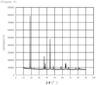
- Figure 4 is a graph showing X-ray diffraction patterns of Li(Ni 0.8 Fe 0.2 ) 0.9 Al 0.1 O 2 having a layered rock salt type structure. This X-ray diffraction was analyzed by Rietvelt analysis to ascertain that the ratio (I (003) /I (104) ) of the diffraction peak intensity I (003) of the (003) plane to the diffraction peak intensity I (104) of the (104) plane is 1.76.
- a target substance (catalyst) whose composition is represented by "Li(Ni 0.8 Fe 0.2 ) 0.95 Al 0.05 O 2 " was prepared in the same manner as in Production Example 1 described above except that the composition of the aqueous solution of the precursor was adjusted. In addition, it was ascertained that the value of I (003) /I (104) of the prepared target substance is 1.76. Further, a three-electrode cell was prepared and electrolysis operation was performed in the same manner as in Production Example 1 described above. As a result, the current value at 1.6 V was 7 mA/cm 2 . The measurement result (cyclic voltammogram) of the cyclic voltammetry is shown in Figure 5 .
- a target substance (catalyst) whose composition is represented by "LiNi 0.8 Al 0.2 O 2 " was prepared in the same manner as in Production Example 1 described above except that the composition of the aqueous solution of the precursor was adjusted. In addition, it was ascertained that the value of I (003) /I (104) of the prepared target substance is within the range of 0.1 to 1.9. Further, a three-electrode cell was prepared and electrolysis operation was performed in the same manner as in Production Example 1 described above. As a result, the current value at 1.6 V was 5 mA/cm 2 .
- a nickel expanded mesh (10 cm ⁇ 10 cm, LW ⁇ 3.7 SW ⁇ 0.9 ST ⁇ 0.8 T) on which a chemical etching treatment was performed by immersing the nickel expanded mesh for 6 minutes in 17.5% hydrochloric acid heated to near the boiling point was prepared as an anode substrate.
- This expanded mesh was subjected to a blast treatment (0.3 MPa) with alumina particles of 60 mesh, and was then immersed for 6 minutes in 20% hydrochloric acid heated to near the boiling point to perform a chemical etching treatment.
- An aqueous solution containing components to be a precursor of a lithium-containing nickel oxide was coated, with a brush, on the surface of the anode substrate after the chemical etching treatment, and was then dried at 80°C for 15 minutes.
- Lithium nitrate, nickel nitrate, iron nitrate, and aluminum nitrate were dissolved in an aqueous citric acid solution such that the respective nitrates formed a predetermined composition, and thus an aqueous solution of a precursor was obtained.
- the obtained aqueous solution of the precursor was coated, with a brush, on the surface of the intermediate layer of the intermediate product obtained above and then dried at 80°C for 15 minutes. Subsequently, the intermediate product was subjected to a thermal treatment at 600°C for 15 minutes in a pure oxygen atmosphere.
- a small-sized zero-gap type electrolytic cell using a neutral separator was prepared using: the obtained anode; a separator (trade name "Zirfon” manufactured by AGFA-Gevaert NV); and an active cathode having a catalyst layer containing Ru and Pr oxide and formed thereon.
- the area of the electrodes was set to 19 cm 2 .
- An electrolyte (25% KOH aqueous solution) was supplied to the anode chamber and the cathode chamber forming the electrolytic cell to perform electrolysis in each chamber at a current density of 6 kA/m 2 for 6 hours in each chamber.
- the overpotential on that occasion was 250 mV.
- An anode was produced in the same manner as in Example 1 described above except that the composition of the catalyst layer was changed to "LiNi 0.8 Fei 0.2 O 2 .” Further, electrolysis was performed in the same manner as in Example 1 described above to find that the overpotential was 350 mV.
- the alkaline water electrolysis anode of the present invention is suitable as, for example, an alkaline water electrolysis anode that forms electrolysis equipment or the like in which electric power having a large output fluctuation, such as renewable energy, is used as a power source.
Abstract
The present invention provides an alkaline water electrolysis anode such that even when electric power having a large output fluctuation, such as renewable energy, is used as a power source, the electrolysis performance is unlikely to be deteriorated and excellent catalytic activity is retained stably over a long period of time. The alkaline water electrolysis anode is an alkaline water electrolysis anode 10 provided with an electrically conductive substrate 2 at least a surface of which contains nickel or a nickel base alloy and a catalyst layer 6 disposed on the surface of the electrically conductive substrate 2, the catalyst layer 6 containing a lithium composite oxide having a rock salt type structure, wherein the lithium composite oxide contains lithium (Li), nickel (Ni), iron (Fe), and aluminum (Al), and has an atom ratio of Li/Ni/Fe/Al/O of (0.4 to 1.1)/(0.4 to 0.8)/(0.05 to 0.2)/(0.05 to 0.2)/2.0.
Description
- The present invention relates to an alkaline water electrolysis anode and a method for producing the same.
- Hydrogen is secondary energy which is suitable for storage and transportation and has small environmental load, and therefore a hydrogen energy system using hydrogen as an energy carrier has been attracting attention. Currently, hydrogen is mainly produced by steam reforming of fossil fuel, or the like. However, from the viewpoint of problems of global warming and exhaustion of fossil fuel, hydrogen production by water electrolysis using renewable energy, such as solar power generation and wind power generation, is important in generic technology. Water electrolysis is low cost, suitable for enlargement of scale, and therefore is a predominant technique for hydrogen production.
- Among the elements which are used for water electrolysis, many of anode materials have an oxygen generation overpotential of exceeding 0.3 V under actual operation conditions. It can be said that there is room for significant improvement in the oxygen generation overpotential as compared to the fact that hydrogen generation and chlorine generation overpotentials utilized in current electrolysis industry are around 0.1 V. Note that when electric power having a large output fluctuation, such as renewable energy, is used as a power source for water electrolysis, an anode capable of stably retaining excellent catalytic activity over a long period of time is in the development stage and has not yet been put into practical use.
- Current practical water electrolysis is largely divided into two. One is alkaline water electrolysis, in which a high-concentration alkali aqueous solution is used for an electrolyte. The other is solid polymer electrolyte water electrolysis, in which a solid polymer electrolyte (SPE) membrane is used for an electrolyte. When large-scale hydrogen production is performed by water electrolysis, it is said that alkaline water electrolysis, in which an inexpensive material, such as an iron group metal including nickel and the like, is used, is more suitable than solid polymer electrolyte water electrolysis, in which an electrode using a large amount of an expensive noble metal is used.
- With respect to the high-concentration alkali aqueous solution, electric conductivity becomes high as the temperature increases, but corrosiveness also becomes high. Therefore, the upper limit of the operation temperature is controlled to about 80 to about 90°C. The electrolytic cell voltage has been improved to 2 V or less at a current density of 0.6 Acm-2 by the development of constitutional materials and various piping materials for an electrolytic cell, which are high-temperature resistant and resistant to a high-concentration alkali aqueous solution, and the development of a low-resistivity separator and an electrode which has an enlarged surface area and has a catalyst applied thereon.
- A nickel-based material which is stable in a high-concentration alkali aqueous solution is used as an alkaline water electrolysis anode, and it has been reported that in the case of alkaline water electrolysis using a stable power source, a nickel-based anode has a life of several decades or longer (Non-Patent Literatures 1 and 2). However, when renewable energy is used as a power source, severe conditions, such as sudden start/shutdown and abrupt load fluctuation, are frequent, and therefore deterioration in performance of the nickel-based anode has been problematic (Non-Patent Literature 3).
- Both of the reaction of producing a nickel oxide and the reaction of reducing the produced nickel oxide progress on a metal surface. Therefore, elimination of an electrode catalyst formed on the metal surface is facilitated with the progress of these reactions. When the electric power for electrolysis is not supplied, the electrolysis stops, and the nickel-based anode is retained at a potential lower than the oxygen generation potential (1.23 V vs. RHE) and higher than the potential of a hydrogen generation cathode, which is a counter electrode, (0.00 V vs. RHE). In the electrolytic cell, electromotive force due to various chemical species is generated, so that the anode potential is retained low, and the reaction of reducing the nickel oxide is facilitated by the progress of a battery reaction. The RHE is the abbreviation of Reversible Hydrogen Electrode.
- A current generated by the battery reaction leaks through piping that connects cells in the case of, for example, an electrolytic stack obtained by combining a plurality of cells, such as an anode chamber and a cathode chamber. Examples of the countermeasure for preventing such leakage of a current include a method of allowing a minute current to flow continuously during shutdown. However, to allow a minute current to flow continuously during shutdown, special power source control is needed, and oxygen and hydrogen are generated at all times, and therefore there is a problem that excessive labor has to be done in terms of operation management. In addition, preventing a battery reaction by removing liquid immediately after shutdown for the purpose of intentionally avoiding a reverse current state is possible, but it cannot be said that such measure is always an adequate approach when operation with electric power having a large output fluctuation, such as renewable energy, is supposed.
- In the past, platinum group metals, platinum group metal oxides, valve metal oxides, iron group oxides, lanthanide group metal oxides, and the like have been utilized as a catalyst for oxygen generation anode (anode catalyst) which is used for alkaline water electrolysis. As other anode catalysts, alloy-based anode catalysts using nickel as a base, such as Ni-Co and Ni-Fe; nickel having an enlarged surface area; spinel-based anode catalysts, such as Co3O4 and NiCo2O4; perovskite-based electrically conductive oxides (ceramic materials), such as LaCoO3 and LaNiO3; noble metal oxides; oxides containing a lanthanide group metal and a noble metal; and the like have also been known (Non-Patent Literature 3).
- In recent years, as the oxygen generation anode which is used for high-concentration alkaline water electrolysis, an alkaline water electrolysis anode obtained by forming a lithium-containing nickel oxide catalyst layer containing lithium and nickel in a predetermined molar ratio on the surface of a nickel substrate (Patent Literature 1) and an alkaline water electrolysis anode obtained by forming a catalyst layer containing a nickel-cobalt-based oxide, and an iridium oxide or a ruthenium oxide on the surface of a nickel substrate (Patent Literature 2) have been proposed.
- It has been reported that the oxygen gas overpotential of a layered rock salt type LiNiO2 catalyst decreases with the addition of Li and the activity becomes highest at the time when the composition is represented by Li0.5Ni0.5O (Non-Patent Literature 4). A catalyst material having high activity and durability is designed using a layered structure, generation of Ni3+, and a particular electronic structure derived from high electron conductivity. It is considered that by doping Li+ into NiO, mobility of Li, a local structure, and an electronic state of an active site (Ni) are adjusted, which enables mixing of Ni into the 3a site of Li and suppression of elution by diffusion paths of Li+, and thereby high oxygen generation activity is retained when the composition is represented by Li0.5Ni0.5O (
Figure 2 ) . - The amount of cations mixing between the 3a site and 3b site can be controlled by adjusting the thermal treatment conditions in the air or in oxygen. From the results of Rietvelt analysis and ICP, it has been found that the lattice constant changes in proportion to the amount of Li by Vegard's law. In addition, it has been known that a sample in which the amount of cations mixed is largest exhibits high durability in an oxygen generation test in a KOH solution. Deterioration of a catalyst is considered to be caused by elimination of Li from a crystal, and the deterioration of the catalyst can be suppressed by increasing the amount of cations mixed. Further, it has been known by operando XAFS measurement during the electrolysis reaction that the layered salt structure of LixNiO2, which is a basic crystalline structure, is retained even after the elimination of Li. Material design to prevent the elution of Li into an electrolyte is important in utilizing a Li-containing metal oxide.
- Furthermore, it has been reported that LiNi0.8Al0.2O2 having a layered rock salt type structure exhibits high oxygen generation activity (Non-Patent Literature 5). It is presumed that Al plays a role of stabilizing the structure during polarization due to a synergistic effect with Ni. The layered rock salt structure has been developed by a thermal treatment in an oxygen gas. Attention is paid on Al3+ doping because of stabilization of Ni3+ in the LiNiO2 layer and suppression of mixing of Ni2+ in the Li+ layer. Moreover, it has been reported that LiNi0.8Fe0.2O2 having a layered rock salt type structure exhibits high oxygen generation activity (Non-Patent Literature 6).
- In addition, a method for producing an anode being such that a nanosheet material containing a NiFe hydroxide and a Ce oxide is formed on a nickel form and being used for electrolysis of water (Patent Literature 3) and a method for producing an anode such that a nanosheet material containing a NiFe hydroxide, Co, Mo, and P is formed on a nickel form (Patent Literature 4) have been proposed. Note that it has been disclosed that a material obtained by forming a NiFe hydroxide on a nickel form is applicable to a sensor for an ampicillin-, nitrate ion-, or tetracycline-based antibiotic (
Patent Literatures 5 and 6). -
- Patent Literature 1:
Japanese Patent Laid-Open No. 2015-86420 - Patent Literature 2:
Japanese Patent Laid-Open No. 2017-190476 - Patent Literature 3:
Chinese Patent Application Publication No. 108447703 - Patent Literature 4:
Chinese Patent Application Publication No. 110344078 - Patent Literature 5:
Chinese Patent Application Publication No. 109254049 - Patent Literature 6:
Chinese Patent Application Publication No. 108107101 -
- Non-Patent Literature 1: P.W.T.Lu, S.Srinivasan, J.Electrochem.Soc.,125,1416(1978)
- Non-Patent Literature 2: C.T.Bowen, Int.J.Hydrogen Energy,9,59(1984)
- Non-Patent Literature 3: S. Mitsushima et al., Electrocatalysis, 8, 422(2017)
- Non-Patent Literature 4: Fu, G.; Wen, X.; Xi, S.; Chen, Z.; Li, W.; Zhang, J.; Anton, T.; Wu, R. Qi, D.; Du, Y.; Cheng, J.; Kelvin, H. L. Z. Tuning the Electronic Structure of NiO via Li Doping for the Fast Oxygen Evolution Reaction. Chem Mater, 2019, 31, 419-428
- Non-Patent Literature 5: Gupta, A.; Chemelewski, W. D.; Buddie Mullins, C.; Goodenough, J. B., High-rate oxygen evolution reaction on Al-doped LiNiO2. Adv Mater 2015, 27 (39), 6063-7
- Non-Patent Literature 6: Zhu, K.; Wu, T.; Zhu, Y.; Li, X.; Li, M.; Lu, R.; Wang, J.; Zhu, X.; Yang, W., Layered Fe-Substituted LiNiO2 Electrocatalysts for High-Efficiency Oxygen Evolution Reaction. ACS Energy Letters 2017, 2 (7), 1654-1660
- However, there has been a problem that even in the alkaline water electrolysis anodes proposed in
Patent Literatures 1 and 2, when electric power having a large output fluctuation, such as renewable energy, is used as a power source, the performance is likely to be lowered, making it difficult to use the anodes stably over a long period of time. In addition, it cannot necessarily be said that even LiNi0.8Al0.2O2 reported inNon-Patent Literature 5 and LiNi0.8Fe0.2O2 reported inNon-Patent Literature 6 are sufficiently highly active, and there has been still room for further improvement. Note that both of the production methods proposed inPatent Literatures 3 and 4 are complicated and cannot necessarily be said to be practical. - The present invention has been completed in view of such problems of the conventional techniques, and an object of the present invention is to provide an alkaline water electrolysis anode such that even when electric power having a large output fluctuation, such as renewable energy, is used as a power source, the electrolysis performance is unlikely to be deteriorated and excellent catalytic activity is retained stably over a long period of time. In addition, another object of the present invention is to provide a method for producing the alkaline water electrolysis anode.
- As a result of diligent studies in order to solve the problems, the present inventors have found that by doping aluminum (Al) and iron (Fe) into a lithium-containing nickel oxide (LiNiO2) having a layered rock salt type structure, these synergistically act to stabilize Ni3+, and thereby a highly active catalyst is obtained, and have completed the present invention.
- That is, according to the present invention, an alkaline water electrolysis anode described below is provided.
- [1] An alkaline water electrolysis anode provided with: an electrically conductive substrate at least a surface of which contains nickel or a nickel base alloy; and a catalyst layer disposed on the surface of the electrically conductive substrate, the catalyst layer containing a lithium composite oxide having a rock salt type structure, wherein the lithium composite oxide contains lithium (Li), nickel (Ni), iron (Fe), and aluminum (Al), and has an atom ratio of Li/Ni/Fe/Al/O of (0.4 to 1.1)/(0.4 to 0.8)/(0.05 to 0.2)/(0.05 to 0.2)/2.0.
- [2] The alkaline water electrolysis anode according to [1], wherein a ratio (I(003)/I(104)) of diffraction peak intensity I(003) of a (003) plane to diffraction peak intensity I(104) of a (104) plane of the catalyst layer, as measured by X-ray diffraction, is 0.1 to 1.9.
- [3] The alkaline water electrolysis anode according to [1] or [2], further provided with an intermediate layer disposed between the electrically conductive substrate and the catalyst layer, the intermediate layer containing a lithium-containing nickel oxide represented by compositional formula LixNi2-xO2 wherein 0.02≤x≤0.5.
Further, according to the present invention, a method for producing an alkaline water electrolysis anode, described below, is provided. - [4] A method for producing an alkaline water electrolysis anode, including: a step of coating an aqueous solution of a precursor containing a lithium component, a nickel component, an iron component, and an aluminum component on a surface of an electrically conductive substrate at least the surface of which contains nickel or a nickel base alloy; and a step of subjecting the electrically conductive substrate on which the aqueous solution of the precursor has been coated to a thermal treatment at 400 to 800°C in an oxygen-containing atmosphere, thereby forming a catalyst layer containing a lithium composite oxide having a rock salt type structure on the surface of the electrically conductive substrate, wherein the lithium composite oxide contains lithium (Li), nickel (Ni), iron (Fe), and aluminum (Al), and has an atom ratio of Li/Ni/Fe/Al/O of (0.4 to 1.1)/(0.4 to 0.8)/(0.05 to 0.2)/(0.05 to 0.2)/2.0.
- [5] The method for producing an alkaline water electrolysis anode according to [4], wherein the electrically conductive substrate on which the aqueous solution of the precursor has been coated is subjected to a thermal treatment in an oxygen-containing atmosphere having an oxygen partial pressure of 0.5 atm or higher.
- The present invention can provide an alkaline water electrolysis anode being such that even when electric power having a large output fluctuation, such as renewable energy, is used as a power source, the electrolysis performance is unlikely to be deteriorated, and excellent catalytic activity is retained over a long period of time. Further, the present invention can provide a method for producing the alkaline water electrolysis anode.
-
- [
Figure 1] Figure 1 is a section view schematically showing one embodiment of an alkaline water electrolysis anode of the present invention. - [
Figure 2] Figure 2 is a schematic diagram showing a state of an oxygen generation anode that is used in an alkaline water electrolysis method. - [
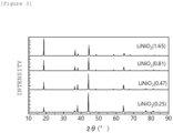
Figure 3] Figure 3 is a graph showing X-ray diffraction patterns of LiNiO2 having a layered rock salt type structure. - [
Figure 4] Figure 4 is a graph showing X-ray diffraction patterns of Li(Ni0.8Fe0.2)0.9Al0.1O2 having a layered rock salt type structure. - [
Figure 5] Figure 5 is a graph showing results (cyclic voltammograms) of cyclic voltammetry measurement. -
Figure 1 is a section view schematically showing one embodiment of an alkaline water electrolysis anode of the present invention. As shown inFigure 1 , an alkalinewater electrolysis anode 10 of the present embodiment is provided with an electricallyconductive substrate 2, anintermediate layer 4 formed on the surface of the electricallyconductive substrate 2, and acatalyst layer 6 formed on the surface of theintermediate layer 4. Hereinafter, the details on the alkaline water electrolysis anode of the present invention (hereinafter, also simply referred to as "anode"). - The electrically
conductive substrate 2 is an electric conductor that conducts electricity for electrolysis and is an element having a function as a carrier that carries theintermediate layer 4 and thecatalyst layer 6. At least a surface of the electrically conductive substrate 2 (the surface on which theintermediate layer 4 and thecatalyst layer 6 are formed) is formed with nickel or a nickel base alloy. That is, the whole of the electricallyconductive substrate 2 may be formed with nickel or a nickel base alloy, or only the surface of the electricallyconductive substrate 2 may be formed with nickel or a nickel base alloy. Specifically, the electricallyconductive substrate 2 may be such that a coating of nickel or a nickel base alloy is formed on the surface of a metal material, such as iron, stainless steel, aluminum, or titanium, by plating or the like. - The thickness of the electrically conductive substrate is preferably 0.05 to 5 mm. The shape of the electrically conductive substrate is preferably a shape having an opening for removing bubbles of oxygen, hydrogen, and the like to be produced by electrolysis. For example, an expanded mesh or a porous expanded mesh can be used as the electrically conductive substrate. When the electrically conductive substrate has a shape having an opening, the aperture ratio of the electrically conductive substrate is preferably 10 to 95%.
- The anode of the present invention is preferably provided with an intermediate layer disposed between the electrically conductive substrate and the catalyst layer. As shown in
Figure 1 , theintermediate layer 4 is a layer formed on the surface of the electricallyconductive substrate 2. Theintermediate layer 4 suppresses corrosion or the like of the electricallyconductive substrate 2 and fixes thecatalyst layer 6 stably to the electricallyconductive substrate 2. In addition, theintermediate layer 4 also serves as a role of supplying a current quickly to thecatalyst layer 6. Theintermediate layer 4 is preferably formed with a lithium-containing nickel oxide represented by composition formula LixNi2-xO2 (0.02≤x≤0.5). When x in the compositional formula is less than 0.02, the electric conductivity is somewhat insufficient in some cases. On the other hand, when x exceeds 0.5, the physical strength and the chemical stability are somewhat lowered in some cases. Theintermediate layer 4 formed with a lithium-containing nickel oxide represented by the compositional formula has enough electric conductivity for electrolysis, and exhibits excellent physical strength and chemical stability even after the use for a long period of time. - The thickness of the intermediate layer is preferably 0.01 µm or more and 100 µm or less, more preferably 0.1 µm or more and 10 µm or less. When the thickness of the intermediate layer is less than 0.01 µm, the above-described functions are not exhibited. On the other hand, even if the thickness of the intermediate layer is set in such a way as to exceed 100 µm, the above-described functions are unlikely to be exhibited because the voltage loss due to the resistance in the intermediate layer is large, and it is somewhat disadvantageous in terms of production costs or the like in some cases.
- The
catalyst layer 6 is a layer that is formed on the surface of theintermediate layer 4 and has catalytic ability. By interposing theintermediate layer 4, thecatalyst layer 6 is more firmly fixed on the electricallyconductive substrate 2. - The catalyst layer is formed with a lithium composite oxide having a rock salt type structure. Then, this lithium composite oxide contains lithium (Li), nickel (Ni), iron (Fe), and aluminum (Al), and has an atom ratio of Li/Ni/Fe/Al/O of (0.4 to 1.1)/(0.4 to 0.8)/(0.05 to 0.2)/(0.05 to 0.2)/2.0. When the catalyst layer formed with a lithium composite oxide having a composition in which Li, Ni, Fe, Al, and O are represented by the above-described ratio is provided, thereby the electrolysis performance is unlikely to be deteriorated and excellent catalyst activity can be retained stably over a long period of time even when electric power having a large output fluctuation, such as renewable energy, is used as a power source.
- The lithium composite oxide that forms the catalyst layer has a layered rock salt type structure. The rock salt type structure of the lithium composite oxide is developed, thereby the electrolysis performance is more unlikely to be deteriorated and further excellent catalytic activity is retained stably. Whether the lithium composite oxide that forms the catalyst layer has a rock salt type structure or not can be checked by analyzing the catalyst layer by X-ray diffraction. For example, diffraction peaks around 2θ = 18° corresponding to the (003) plane and around 2θ = 44° corresponding to the (104) plane of the catalyst layer are measured by X-ray diffraction using Cu-Kα rays. When the relative intensity ratio between these diffraction peaks (I(003)/I(104)) is larger, it indicates that the layered rock salt type structure has been developed more. More specifically, the ratio (I(003)/I(104)) of the diffraction peak intensity I(003) of the (003) plane to the diffraction peak intensity I(104) of the (104) plane of the catalyst layer, measured by X-ray diffraction, is preferably 0.1 to 1.9, more preferably 0.2 to 1.8.
Figure 3 is a graph showing X-ray diffraction patterns of LiNiO2 having a layered rock salt type structure. It has been ascertained that the ratio (I(003)/I(104)) of the diffraction peak intensity I(003) of the (003) plane to the diffraction peak intensity I(104) of the (104) plane is 0.1 to 1.9 by Rietvelt analysis of these X-ray diffraction patterns. Note that it has also been confirmed that when the X-ray diffraction patterns of lithium complex oxides which are used for the anode of the present embodiment and contain Li, Ni, Fe, and Al are analyzed by Rietvelt analysis, the ratio (I(003)/I(104)) of the diffraction peak intensity I(003) of the (003) plane to the diffraction peak intensity I(104) of the (104) plane is within the range of 0.1 to 1.9 and the lithium complex oxides, as well as LiNiO2 described above, have a layered rock salt type structure. - The thickness of the catalyst layer is preferably 0.01 µm or more and 100 µm or less, more preferably 0.1 µm or more and 10 µm or less. When the thickness of the catalyst layer is less than 0.01 µm, the above-described functions are not exhibited. On the other hand, even if the thickness of the catalyst layer is set in such a way as to exceed 100 µm, the above-described functions are not exhibited sufficiently because the voltage loss due to the resistance in the catalyst layer is large, and it is somewhat disadvantageous in terms of production costs or the like in some cases.
- Next, a method for producing an alkaline water electrolysis anode of the present invention will be described. The method for producing an anode, which will be described below, is a method for suitably producing the above-described alkaline water electrolysis anode. The method for producing an anode of the present invention includes: a step (first coating step) of coating an aqueous solution of a precursor containing a lithium component, a nickel component, an iron component, and an aluminum component on a surface of an electrically conductive substrate; and a step (catalyst layer formation step) of subjecting the electrically conductive substrate on which the aqueous solution of the precursor has been coated to a thermal treatment at 400 to 800°C in an oxygen-containing atmosphere, thereby forming a catalyst layer containing a lithium composite oxide having a rock salt type structure on the surface of the electrically conductive substrate.
- Note that, if necessary, an intermediate layer can be disposed between the electrically conductive substrate and the catalyst layer, as described above. A method for producing an anode in which an intermediate layer is disposed further includes, prior to the above-described first coating step, a step (second coating step) of coating an aqueous solution containing a lithium ion and a nickel ion on the surface of the electrically conductive substrate; and a step (intermediate layer formation step) of subjecting the electrically conductive substrate on which the aqueous solution has been coated to a thermal treatment, thereby forming, on the surface of the electrically conductive substrate, an intermediate layer containing a lithium-containing nickel oxide represented by compositional formula LixNi2-xO2 wherein 0.02≤x≤0.5.
- The electrically conductive substrate is preferably subjected to a chemical etching treatment in advance for the purpose of removing contamination particles of a metal, an organic substance, and the like on the surface before forming the intermediate layer and the catalyst layer. The consumption of the electrically conductive substrate by the chemical etching treatment is preferably set to about 30 g/m2 or more and about 400 g/m2 or less. In addition, the surface of the electrically conductive substrate is preferably subjected to a roughening treatment in advance for the purpose of enhancing the adhesiveness with the intermediate layer and the catalyst layer. Examples of the means for the roughening treatment include a blast treatment in which a powder is sprayed, an etching treatment using an acid that can dissolve the substrate, and plasma spraying.
- In the second coating step, an aqueous solution containing a lithium ion and a nickel ion is coated on the surface of the electrically conductive substrate. The intermediate layer is formed by a so-called thermal decomposition method. When the intermediate layer is formed by the thermal decomposition method, an aqueous solution of a precursor of the intermediate layer is first prepared. As the precursor containing a lithium component, a known precursor, such as lithium nitrate, lithium carbonate, lithium chloride, lithium hydroxide, and a lithium carboxylate, can be used. Examples of the lithium carboxylate include lithium formate and lithium acetate. As the precursor containing a nickel component, a known precursor, such as nickel nitrate, nickel carbonate, nickel chloride, and a nickel carboxylate, can be used. Examples of the nickel carboxylate include nickel formate and nickel acetate. It is particularly preferable to use at least one of a lithium carboxylate and a nickel carboxylate in particular as the precursor because thereby a dense intermediate layer can be formed even when calcination is performed at a low temperature, as will be described later.
- In the intermediate layer formation step, the electrically conductive substrate on which the aqueous solution has been coated is subjected to a thermal treatment. Thereby, the intermediate layer containing a lithium-containing nickel oxide represented by compositional formula LixNi2-xO2 (0.02≤x≤0.5) can be formed on the surface of the electrically conductive substrate. The thermal treatment temperature at the time when the intermediate layer is formed by the thermal decomposition method can appropriately be set. When the decomposition temperature of the precursor and the production costs are taken into consideration, the thermal treatment temperature is preferably set to 450 to 600°C, more preferably 450 to 550°C. For example, the decomposition temperature of lithium nitrate is about 430°C, and the decomposition temperature of nickel acetate is about 373°C. When the thermal treatment temperature is set to 450°C or higher, thereby each component can more surely be decomposed. When the thermal treatment temperature is set in such a way as to exceed 600°C, the oxidation of the electrically conductive substrate easily progresses, and the electrode resistance increases to bring about an increase in the voltage loss in some cases. The thermal treatment time may appropriately be set taking the reaction rate, the productivity, the oxidation resistance at the surface of the intermediate layer, and the like into consideration.
- By appropriately setting the number of times of coating of the aqueous solution in the above-described coating step, the thickness of the intermediate layer to be formed can be controlled. Note that: the coating and drying of the aqueous solution may be repeated for every layer until the uppermost layer is formed, and thereafter the thermal treatment may be performed on the whole layers, or the coating of the aqueous solution and the thermal treatment (pre-treatment) may be repeated for every layer to until the uppermost layer is formed, and the thermal treatment may thereafter be performed on the whole layers. The temperature of the pre-treatment and the temperature of the thermal treatment on the whole layers may be the same or different. In addition, the time for the pre-treatment is preferably made shorter than the time for the thermal treatment on the whole layers.
- In the first coating step, an aqueous solution of a precursor containing a lithium component, a nickel component, an iron component, and an aluminum component is coated on the surface of the electrically conductive substrate. The catalyst layer is formed by a so-called thermal decomposition method. When the catalyst layer is formed by the thermal decomposition method, an aqueous solution of a precursor of the catalyst layer is first prepared. As the precursor containing a lithium component, a known precursor, such as lithium nitrate, lithium carbonate, lithium chloride, lithium hydroxide, and a lithium carboxylate, can be used. Examples of the lithium carboxylate include lithium formate and lithium acetate. As the precursor containing a nickel component, a known precursor, such as nickel nitrate, nickel carbonate, nickel chloride, and a nickel carboxylate, can be used. Examples of the nickel carboxylate include nickel formate and nickel acetate. It is particularly preferable to use at least one of a lithium carboxylate and a nickel carboxylate in particular as the precursor because thereby a dense catalyst layer can be formed even when calcination is performed at a low temperature, as will be described later.
- As the precursor containing an iron component, a known precursor, such as iron nitrate, iron carbonate, iron chloride, and an iron carboxylate, can be used. As the precursor containing an aluminum component, a known precursor, such as aluminum nitrate, aluminum carbonate, aluminum chloride, and an aluminum carboxylate, can be used.
- In the catalyst layer formation step, the electrically conductive substrate on which the aqueous solution of the precursor has been coated is subjected to a thermal treatment at 400 to 800°C in an oxygen-containing atmosphere. Thereby, the catalyst layer containing a lithium composite oxide having a rock salt type structure can be formed on the surface of the electrically conductive substrate. When the decomposition temperature of the precursor, the production costs, and the like are taken into consideration, the thermal treatment temperature is more preferably set to 450 to 550°C. When the thermal treatment temperature is set to 450°C or higher, thereby each component can more surely be decomposed. When the thermal treatment temperature is excessively high, the oxidation of the electrically conductive substrate easily progresses, and the electrode resistance increases to bring about an increase in the voltage loss in some cases. The thermal treatment time may appropriately be set taking the reaction rate, the productivity, the oxidation resistance at the surface of the catalyst layer, and the like into consideration.
- For example, lithium nitrate, nickel nitrate, iron nitrate, and aluminum nitrate are dissolved in an aqueous citric acid solution obtained by dissolving citric acid in ultrapure water such that proportions of the respective nitrates are intended in the composition, and thereby an aqueous solution of a precursor for forming a catalyst layer can be obtained. Note that the precursor obtained by evaporating the solution of the precursor to dryness is calcined, for example, at 600 to 800°C for 2 to 15 hours, and thereby an alkaline water electrolysis catalyst (target substance) can be obtained.
- The oxygen partial pressure in the oxygen-containing atmosphere at the time when the electrically conductive substrate on which the aqueous solution of the precursor has been coated is subjected to the thermal treatment is preferably set to 0.5 atm or higher, more preferably 0.9 atm or higher. In addition, the flow rate of the gas containing oxygen to be supplied is preferably controlled to 5 mL/min or less, more preferably 2.5 mL/min, in terms of oxygen. When the flow rate of the gas is excessively large (excessively fast), Li is likely to excessively volatilize and production of the oxide is excessively accelerated in some cases, and therefore the composition of the catalyst is likely to deviate from the intended composition in some cases.
- The alkaline water electrolysis anode of the present invention can be used as an oxygen generation anode at the time when alkaline water is electrolyzed. That is, use of the anode of the present invention can form an electrolytic cell, such as an alkaline water electrolytic cell. The types, constitution, and the like of the cathode and separator to be used together with the above-described anode are not particularly limited, and a cathode and a separator which are used in conventional alkaline water electrolysis can be used.
- As the cathode, a substrate made of a material that is bearable to alkaline water electrolysis and a catalyst having a small cathode overpotential are preferably selected and used. As the cathode substrate, a nickel substrate, or a cathode substrate obtained by forming an active cathode by coating the nickel substrate can be used. Examples of the shape of the cathode substrate include an expanded mesh and a porous expanded mesh in addition to a plate shape.
- The cathode material includes porous nickel having a large surface area, a Ni-Mo-based material, and the like. Besides, the cathode material includes Raney nickel-based materials, such as Ni-Al, Ni-Zn, and Ni-Co-Zn; sulfide-based materials, such as Ni-S; and hydrogen absorbing alloy-based materials, such as Ti2Ni; and the like. The catalyst preferably has characteristics of low hydrogen overpotential, high stability against short-circuit, high poisoning resistance, and the like. As other catalysts, metals, such as platinum, palladium, ruthenium, and iridium, and oxides thereof are preferable.
- As the electrolysis separator, asbestos, non-woven fabric, an ion-exchange membrane, a porous polymer membrane, and a composite membrane of an inorganic substance and an organic polymer, and the like can be used. Specifically, an ion-permeable separator such that organic fiber cloth is incorporated in a mixture of a hydrophilic inorganic material, such as a calcium phosphate compound and calcium fluoride, and an organic binding material, such as polysulfone, polypropylene, and polyvinylidene fluoride, can be used. In addition, an ion-permeable separator such that stretched organic fiber cloth is incorporated in a film-forming mixture of an inorganic hydrophilic substance in the form of particles, such as oxides and hydroxides of antimony and zirconium, and an organic binder, such as a fluorocarbon polymer, polysulfone, polypropylene, polyvinyl chloride, and polyvinyl butyral can be used.
- By using an alkaline water electrolytic cell using the anode of the present invention as a constitutional element, a high-concentration alkali aqueous solution can be electrolyzed. The alkali aqueous solution that is used as the electrolyte is preferably an aqueous solution of an alkaline metal hydroxide, such as potassium hydroxide (KOH) or sodium hydroxide (NaOH). The concentration of the alkali aqueous solution is preferably 1.5% by mass or more and 40% by mass or less. In addition, the concentration of the alkali aqueous solution is preferably 15% by mass or more and 40% by mass or less because the electric conductivity is large, and the electric power consumption can be suppressed. Further, when the costs, the corrosiveness, the viscosity, the operability, and the like are taken into consideration, the concentration of the alkali aqueous solution is preferably 20% by mass or more and 30% by mass or less.
- Hereinafter, the present invention will specifically be described based on Examples, but the present invention is not limited to these Examples. Note that "parts" and "%" in Examples and Comparative Examples are each on a mass basis unless otherwise noticed.
- Lithium nitrate, nickel nitrate, iron nitrate, and aluminum nitrate were dissolved in an aqueous citric acid solution obtained by dissolving citric acid in ultrapure water such that the respective nitrates formed a predetermined composition, and thus an aqueous solution of a precursor was prepared. The prepared aqueous solution of the precursor was evaporated to dryness to obtain the precursor. The obtained precursor was calcined at 800°C for 15 hours to obtain a target substance in the form of a powder. A solution obtained by dissolving part of the obtained standard substance in an acid was used as a sample, and the composition was analyzed by inductively coupled plasma (ICP) emission spectrophotometry. As a result, it was ascertained that the composition of the obtained target substance (catalyst) is represented by "Li(Ni0.8Fe0.2)0.9Al0.1O2."
Figure 4 is a graph showing X-ray diffraction patterns of Li(Ni0.8Fe0.2)0.9Al0.1O2 having a layered rock salt type structure. This X-ray diffraction was analyzed by Rietvelt analysis to ascertain that the ratio (I(003)/I(104)) of the diffraction peak intensity I(003) of the (003) plane to the diffraction peak intensity I(104) of the (104) plane is 1.76. - To 2 mL of ethanol, 5 mg of the target substance (catalyst) and 45 µL of a 5% Nafion solution were added, and a resultant mixture was shaken using ultrasonic waves for 1 hour to prepare a catalyst ink. On a RDE (GC) electrode having a diameter of 5 mm, 24 µL (catalyst: 0.3 mg/cm2) of the prepared catalyst ink was coated. Then, electrolysis operation was performed at 30±1°C using a three-electrode cell made of PFA, described below. Note that cyclic voltammetry (0.5 to 1.6 V vs. RHE, 200 mV/s, 100 cycles) was performed as a pre-treatment, and a current was measured at a potential of 1.1 to 1.7 V and a sweep rate of 5 mV/s while the electrode was rotated at 1,600 rpm. As a result, the current value at 1.6 V was 20 mA/cm2. The measurement result (cyclic voltammogram) of the cyclic voltammetry is shown in
Figure 5 . -
- Working electrode: Ni wire etched with boiling hydrochloric acid for 6 minutes
- Reference electrode: reversible hydrogen electrode (RHE)
- Counter electrode: Pt coil
- Electrolyte: 250 mL of 1.0M KOH aqueous solution
- A target substance (catalyst) whose composition is represented by "Li(Ni0.8Fe0.2)0.95Al0.05O2" was prepared in the same manner as in Production Example 1 described above except that the composition of the aqueous solution of the precursor was adjusted. In addition, it was ascertained that the value of I(003)/I(104) of the prepared target substance is 1.76. Further, a three-electrode cell was prepared and electrolysis operation was performed in the same manner as in Production Example 1 described above. As a result, the current value at 1.6 V was 7 mA/cm2. The measurement result (cyclic voltammogram) of the cyclic voltammetry is shown in
Figure 5 . - A target substance (catalyst) whose composition is represented by "LiNi0.8Fe0.2O2" was prepared in the same manner as in Production Example 1 described above except that the composition of the aqueous solution of the precursor was adjusted. In addition, it was ascertained that the value of I(003)/I(104) of the prepared target substance is within the range of 0.1 to 1.9. Further, a three-electrode cell was prepared and electrolysis operation was performed in the same manner as in Production Example 1 described above. As a result, the current value at 1.6 V was 5 mA/cm2. The measurement result (cyclic voltammogram) of the cyclic voltammetry is shown in
Figure 5 . - A target substance (catalyst) whose composition is represented by "LiNi0.8Al0.2O2" was prepared in the same manner as in Production Example 1 described above except that the composition of the aqueous solution of the precursor was adjusted. In addition, it was ascertained that the value of I(003)/I(104) of the prepared target substance is within the range of 0.1 to 1.9. Further, a three-electrode cell was prepared and electrolysis operation was performed in the same manner as in Production Example 1 described above. As a result, the current value at 1.6 V was 5 mA/cm2.
- A nickel expanded mesh (10 cm × 10 cm, LW × 3.7 SW × 0.9 ST × 0.8 T) on which a chemical etching treatment was performed by immersing the nickel expanded mesh for 6 minutes in 17.5% hydrochloric acid heated to near the boiling point was prepared as an anode substrate. This expanded mesh was subjected to a blast treatment (0.3 MPa) with alumina particles of 60 mesh, and was then immersed for 6 minutes in 20% hydrochloric acid heated to near the boiling point to perform a chemical etching treatment. An aqueous solution containing components to be a precursor of a lithium-containing nickel oxide was coated, with a brush, on the surface of the anode substrate after the chemical etching treatment, and was then dried at 80°C for 15 minutes. Subsequently, the anode substrate was subjected to a thermal treatment at 600°C for 15 minutes in an oxygen atmosphere. The treatments from the coating of the aqueous solution to the thermal treatment were repeated 20 times to obtain an intermediate product having an intermediate layer (composition: Li0.5Ni1.5O2) formed on the surface of the anode substrate.
- Lithium nitrate, nickel nitrate, iron nitrate, and aluminum nitrate were dissolved in an aqueous citric acid solution such that the respective nitrates formed a predetermined composition, and thus an aqueous solution of a precursor was obtained. The obtained aqueous solution of the precursor was coated, with a brush, on the surface of the intermediate layer of the intermediate product obtained above and then dried at 80°C for 15 minutes. Subsequently, the intermediate product was subjected to a thermal treatment at 600°C for 15 minutes in a pure oxygen atmosphere. The treatments from the coating of the aqueous solution of the precursor to the thermal treatment were repeated 20 times to obtain an anode in which a catalyst layer (composition: Li (Ni0.8Fe0.2)0.9Al0.1O2) was formed on the surface of the intermediate layer. Note that it was ascertained that the value of I(003)/I(104) of the formed catalyst layer is 1.76.
- A small-sized zero-gap type electrolytic cell using a neutral separator was prepared using: the obtained anode; a separator (trade name "Zirfon" manufactured by AGFA-Gevaert NV); and an active cathode having a catalyst layer containing Ru and Pr oxide and formed thereon. The area of the electrodes was set to 19 cm2. An electrolyte (25% KOH aqueous solution) was supplied to the anode chamber and the cathode chamber forming the electrolytic cell to perform electrolysis in each chamber at a current density of 6 kA/m2 for 6 hours in each chamber. The overpotential on that occasion was 250 mV. Subsequently, the anode and the cathode were brought into a short-circuit state (0 kA/m2) to shut down the electrolysis for 15 hours. Shutdown tests in which the operation from the electrolysis to the shutdown was defined as 1 cycle were conducted. As a result, it was ascertained that the voltage was kept stable in the shutdown tests of 20 times.
- An anode was produced in the same manner as in Example 1 described above except that the composition of the catalyst layer was changed to "LiNi0.8Fei0.2O2." Further, electrolysis was performed in the same manner as in Example 1 described above to find that the overpotential was 350 mV.
- The alkaline water electrolysis anode of the present invention is suitable as, for example, an alkaline water electrolysis anode that forms electrolysis equipment or the like in which electric power having a large output fluctuation, such as renewable energy, is used as a power source.
-
- 2
- Electrically conductive substrate
- 4
- Intermediate layer
- 6
- Catalyst layer
- 10
- Alkaline water electrolysis anode
Claims (5)
- An alkaline water electrolysis anode comprising:an electrically conductive substrate at least a surface of which comprises nickel or a nickel base alloy; anda catalyst layer disposed on the surface of the electrically conductive substrate, the catalyst layer comprising a lithium composite oxide having a rock salt type structure, whereinthe lithium composite oxide comprises lithium (Li), nickel (Ni), iron (Fe), and aluminum (Al), and has an atom ratio of Li/Ni/Fe/Al/O of (0.4 to 1.1)/(0.4 to 0.8)/(0.05 to 0.2)/(0.05 to 0.2)/2.0.
- The alkaline water electrolysis anode according to claim 1, wherein a ratio (I(003)/I(104)) of diffraction peak intensity I(003) of a (003) plane to diffraction peak intensity I(104) of a (104) plane of the catalyst layer, as measured by X-ray diffraction, is 0.1 to 1.9.
- The alkaline water electrolysis anode according to claim 1 or 2, further comprising an intermediate layer disposed between the electrically conductive substrate and the catalyst layer, the intermediate layer comprising a lithium-containing nickel oxide represented by compositional formula LixNi2-xO2 wherein 0.02≤x≤0.5.
- A method for producing an alkaline water electrolysis anode, comprising:a step of coating an aqueous solution of a precursor comprising a lithium component, a nickel component, an iron component, and an aluminum component on a surface of an electrically conductive substrate at least the surface of which comprises nickel or a nickel base alloy; anda step of subjecting the electrically conductive substrate on which the aqueous solution of the precursor has been coated to a thermal treatment at 400 to 800°C in an oxygen-containing atmosphere, thereby forming a catalyst layer comprising a lithium composite oxide having a rock salt type structure on the surface of the electrically conductive substrate, whereinthe lithium composite oxide comprises lithium (Li), nickel (Ni), iron (Fe), and aluminum (Al), and has an atom ratio of Li/Ni/Fe/Al/O of (0.4 to 1.1)/(0.4 to 0.8)/(0.05 to 0.2)/(0.05 to 0.2)/2.0.
- The method for producing an alkaline water electrolysis anode according to claim 4, wherein the electrically conductive substrate on which the aqueous solution of the precursor has been coated is subjected to a thermal treatment in an oxygen-containing atmosphere having an oxygen partial pressure of 0.5 atm or higher.
Applications Claiming Priority (2)
| Application Number | Priority Date | Filing Date | Title |
|---|---|---|---|
| JP2020129161A JP2022025951A (en) | 2020-07-30 | 2020-07-30 | Alkaline water electrolysis anode and production method thereof |
| PCT/JP2021/028171 WO2022025208A1 (en) | 2020-07-30 | 2021-07-29 | Anode for alkaline water electrolysis and method for producing same |
Publications (1)
| Publication Number | Publication Date |
|---|---|
| EP4190944A1 true EP4190944A1 (en) | 2023-06-07 |
Family
ID=80036336
Family Applications (1)
| Application Number | Title | Priority Date | Filing Date |
|---|---|---|---|
| EP21850577.4A Pending EP4190944A1 (en) | 2020-07-30 | 2021-07-29 | Anode for alkaline water electrolysis and method for producing same |
Country Status (7)
| Country | Link |
|---|---|
| US (1) | US20230279566A1 (en) |
| EP (1) | EP4190944A1 (en) |
| JP (1) | JP2022025951A (en) |
| KR (1) | KR20230028784A (en) |
| CN (1) | CN116057209A (en) |
| CA (1) | CA3186983A1 (en) |
| WO (1) | WO2022025208A1 (en) |
Family Cites Families (8)
| Publication number | Priority date | Publication date | Assignee | Title |
|---|---|---|---|---|
| JP2015086420A (en) | 2013-10-29 | 2015-05-07 | 国立大学法人横浜国立大学 | Anode for alkali water electrolysis |
| JP6615682B2 (en) | 2016-04-12 | 2019-12-04 | デノラ・ペルメレック株式会社 | Anode for alkaline water electrolysis and method for producing anode for alkaline water electrolysis |
| JP6889446B2 (en) * | 2016-09-09 | 2021-06-18 | デノラ・ペルメレック株式会社 | Manufacturing method of anode for alkaline water electrolysis and anode for alkaline water electrolysis |
| CN108107101B (en) | 2017-12-12 | 2020-02-07 | 中国科学院合肥物质科学研究院 | Three-dimensional carbon cloth/nickel iron layered hydroxide nanosheet composite material and application thereof |
| JP7273024B2 (en) * | 2018-03-07 | 2023-05-12 | デノラ・ペルメレック株式会社 | Electrode for electrolysis and method for manufacturing the same |
| CN108447703B (en) | 2018-03-16 | 2019-07-19 | 安徽师范大学 | A kind of ferronickel double-metal hydroxide@ceria heterogeneous structural nano sheet material, preparation method and applications |
| CN109254049B (en) | 2018-11-05 | 2021-01-29 | 济南大学 | Preparation method and application of ampicillin sensor |
| CN110344078B (en) | 2019-07-03 | 2021-04-13 | 湖北大学 | Foamed nickel @ cobalt molybdenum phosphide/nickel iron double hydroxide electrode and preparation method and application thereof |
-
2020
- 2020-07-30 JP JP2020129161A patent/JP2022025951A/en active Pending
-
2021
- 2021-07-29 EP EP21850577.4A patent/EP4190944A1/en active Pending
- 2021-07-29 US US18/005,796 patent/US20230279566A1/en active Pending
- 2021-07-29 KR KR1020237002579A patent/KR20230028784A/en unknown
- 2021-07-29 CN CN202180058545.6A patent/CN116057209A/en active Pending
- 2021-07-29 WO PCT/JP2021/028171 patent/WO2022025208A1/en active Application Filing
- 2021-07-29 CA CA3186983A patent/CA3186983A1/en active Pending
Also Published As
| Publication number | Publication date |
|---|---|
| WO2022025208A1 (en) | 2022-02-03 |
| JP2022025951A (en) | 2022-02-10 |
| KR20230028784A (en) | 2023-03-02 |
| US20230279566A1 (en) | 2023-09-07 |
| CA3186983A1 (en) | 2022-02-03 |
| CN116057209A (en) | 2023-05-02 |
Similar Documents
| Publication | Publication Date | Title |
|---|---|---|
| EP3763849B1 (en) | Electrolysis electrode and method for manufacturing same | |
| EP3511443B1 (en) | Method for producing anode for alkaline water electrolysis and anode for alkaline water electolysis | |
| EP3940117A1 (en) | Alkaline water electrolysis method and alkaline water electrolysis anode | |
| JP2003508877A (en) | Anode structure of fuel cell for obtaining resistance to voltage reversal | |
| EP4119700A1 (en) | Alkaline water electrolysis method, and anode for alkaline water electrolysis | |
| Ai et al. | Performance and stability of nano-structured Pd and Pd0. 95M0. 05 (M= Mn, Co, Ce, and Gd) infiltrated Y2O3–ZrO2 oxygen electrodes of solid oxide electrolysis cells | |
| EP4190944A1 (en) | Anode for alkaline water electrolysis and method for producing same | |
| EP4230773A1 (en) | Anode for alkaline water electrolysis and method for producing same | |
| EP4230772A1 (en) | Anode for alkaline water electrolysis and method for producing same | |
| WO2024101105A1 (en) | Positive electrode for electrolysis and method for producing same |
Legal Events
| Date | Code | Title | Description |
|---|---|---|---|
| STAA | Information on the status of an ep patent application or granted ep patent |
Free format text: STATUS: THE INTERNATIONAL PUBLICATION HAS BEEN MADE |
|
| PUAI | Public reference made under article 153(3) epc to a published international application that has entered the european phase |
Free format text: ORIGINAL CODE: 0009012 |
|
| STAA | Information on the status of an ep patent application or granted ep patent |
Free format text: STATUS: REQUEST FOR EXAMINATION WAS MADE |
|
| 17P | Request for examination filed |
Effective date: 20221230 |
|
| AK | Designated contracting states |
Kind code of ref document: A1 Designated state(s): AL AT BE BG CH CY CZ DE DK EE ES FI FR GB GR HR HU IE IS IT LI LT LU LV MC MK MT NL NO PL PT RO RS SE SI SK SM TR |
|
| DAV | Request for validation of the european patent (deleted) | ||
| DAX | Request for extension of the european patent (deleted) |