EP4190694B1 - Überwachungssystem für eine offshore-infrastruktur - Google Patents
Überwachungssystem für eine offshore-infrastruktur Download PDFInfo
- Publication number
- EP4190694B1 EP4190694B1 EP21383089.6A EP21383089A EP4190694B1 EP 4190694 B1 EP4190694 B1 EP 4190694B1 EP 21383089 A EP21383089 A EP 21383089A EP 4190694 B1 EP4190694 B1 EP 4190694B1
- Authority
- EP
- European Patent Office
- Prior art keywords
- offshore
- infrastructure
- controller
- wind turbine
- unmanned
- Prior art date
- Legal status (The legal status is an assumption and is not a legal conclusion. Google has not performed a legal analysis and makes no representation as to the accuracy of the status listed.)
- Active
Links
Images
Classifications
-
- G—PHYSICS
- G05—CONTROLLING; REGULATING
- G05D—SYSTEMS FOR CONTROLLING OR REGULATING NON-ELECTRIC VARIABLES
- G05D1/00—Control of position, course, altitude or attitude of land, water, air or space vehicles, e.g. using automatic pilots
- G05D1/60—Intended control result
- G05D1/656—Interaction with payloads or external entities
- G05D1/689—Pointing payloads towards fixed or moving targets
-
- B—PERFORMING OPERATIONS; TRANSPORTING
- B63—SHIPS OR OTHER WATERBORNE VESSELS; RELATED EQUIPMENT
- B63B—SHIPS OR OTHER WATERBORNE VESSELS; EQUIPMENT FOR SHIPPING
- B63B81/00—Repairing or maintaining vessels
-
- B—PERFORMING OPERATIONS; TRANSPORTING
- B63—SHIPS OR OTHER WATERBORNE VESSELS; RELATED EQUIPMENT
- B63B—SHIPS OR OTHER WATERBORNE VESSELS; EQUIPMENT FOR SHIPPING
- B63B79/00—Monitoring properties or operating parameters of vessels in operation
- B63B79/10—Monitoring properties or operating parameters of vessels in operation using sensors, e.g. pressure sensors, strain gauges or accelerometers
- B63B79/15—Monitoring properties or operating parameters of vessels in operation using sensors, e.g. pressure sensors, strain gauges or accelerometers for monitoring environmental variables, e.g. wave height or weather data
-
- B—PERFORMING OPERATIONS; TRANSPORTING
- B63—SHIPS OR OTHER WATERBORNE VESSELS; RELATED EQUIPMENT
- B63B—SHIPS OR OTHER WATERBORNE VESSELS; EQUIPMENT FOR SHIPPING
- B63B79/00—Monitoring properties or operating parameters of vessels in operation
- B63B79/40—Monitoring properties or operating parameters of vessels in operation for controlling the operation of vessels, e.g. monitoring their speed, routing or maintenance schedules
-
- B—PERFORMING OPERATIONS; TRANSPORTING
- B64—AIRCRAFT; AVIATION; COSMONAUTICS
- B64U—UNMANNED AERIAL VEHICLES [UAV]; EQUIPMENT THEREFOR
- B64U10/00—Type of UAV
- B64U10/10—Rotorcrafts
- B64U10/13—Flying platforms
- B64U10/14—Flying platforms with four distinct rotor axes, e.g. quadcopters
-
- B—PERFORMING OPERATIONS; TRANSPORTING
- B64—AIRCRAFT; AVIATION; COSMONAUTICS
- B64U—UNMANNED AERIAL VEHICLES [UAV]; EQUIPMENT THEREFOR
- B64U80/00—Transport or storage specially adapted for UAVs
- B64U80/80—Transport or storage specially adapted for UAVs by vehicles
- B64U80/84—Waterborne vehicles
-
- G—PHYSICS
- G01—MEASURING; TESTING
- G01M—TESTING STATIC OR DYNAMIC BALANCE OF MACHINES OR STRUCTURES; TESTING OF STRUCTURES OR APPARATUS, NOT OTHERWISE PROVIDED FOR
- G01M99/00—Subject matter not provided for in other groups of this subclass
- G01M99/005—Testing of complete machines, e.g. washing-machines or mobile phones
-
- B—PERFORMING OPERATIONS; TRANSPORTING
- B63—SHIPS OR OTHER WATERBORNE VESSELS; RELATED EQUIPMENT
- B63B—SHIPS OR OTHER WATERBORNE VESSELS; EQUIPMENT FOR SHIPPING
- B63B35/00—Vessels or similar floating structures specially adapted for specific purposes and not otherwise provided for
- B63B2035/006—Unmanned surface vessels, e.g. remotely controlled
- B63B2035/007—Unmanned surface vessels, e.g. remotely controlled autonomously operating
-
- B—PERFORMING OPERATIONS; TRANSPORTING
- B63—SHIPS OR OTHER WATERBORNE VESSELS; RELATED EQUIPMENT
- B63B—SHIPS OR OTHER WATERBORNE VESSELS; EQUIPMENT FOR SHIPPING
- B63B35/00—Vessels or similar floating structures specially adapted for specific purposes and not otherwise provided for
- B63B35/44—Floating buildings, stores, drilling platforms, or workshops, e.g. carrying water-oil separating devices
- B63B2035/4433—Floating structures carrying electric power plants
- B63B2035/446—Floating structures carrying electric power plants for converting wind energy into electric energy
-
- B—PERFORMING OPERATIONS; TRANSPORTING
- B64—AIRCRAFT; AVIATION; COSMONAUTICS
- B64U—UNMANNED AERIAL VEHICLES [UAV]; EQUIPMENT THEREFOR
- B64U2101/00—UAVs specially adapted for particular uses or applications
- B64U2101/25—UAVs specially adapted for particular uses or applications for manufacturing or servicing
- B64U2101/26—UAVs specially adapted for particular uses or applications for manufacturing or servicing for manufacturing, inspections or repairs
-
- B—PERFORMING OPERATIONS; TRANSPORTING
- B64—AIRCRAFT; AVIATION; COSMONAUTICS
- B64U—UNMANNED AERIAL VEHICLES [UAV]; EQUIPMENT THEREFOR
- B64U2101/00—UAVs specially adapted for particular uses or applications
- B64U2101/30—UAVs specially adapted for particular uses or applications for imaging, photography or videography
- B64U2101/31—UAVs specially adapted for particular uses or applications for imaging, photography or videography for surveillance
-
- G—PHYSICS
- G05—CONTROLLING; REGULATING
- G05D—SYSTEMS FOR CONTROLLING OR REGULATING NON-ELECTRIC VARIABLES
- G05D2105/00—Specific applications of the controlled vehicles
- G05D2105/80—Specific applications of the controlled vehicles for information gathering, e.g. for academic research
- G05D2105/89—Specific applications of the controlled vehicles for information gathering, e.g. for academic research for inspecting structures, e.g. wind mills, bridges, buildings or vehicles
Definitions
- the present disclosure relates to surveillance systems for an offshore infrastructure and to surveillance methods for an offshore infrastructure.
- Offshore infrastructures or installations may require frequent inspections to ensure an efficient operation.
- Examples of offshore infrastructures may be offshore wind turbines, oil and gas equipment, offshore electrical substations or underwater power cables.
- Several offshore wind turbines may be connected trough underwater power cables to an offshore electrical substation.
- the voltage of the energy produced by the offshore wind turbines is stepped up to a higher voltage to reduce the electrical loss during the transport from the offshore electrical substation to an onshore electrical substation through underwater power cables.
- Maintenance operators may be transported by a boat to the offshore infrastructure to perform a visual inspection and/or to monitor the operation of the offshore infrastructure.
- Offshore infrastructures are generally far from the coast. Navigating from a harbor to the offshore infrastructure may require a relative long time. These operations thus involve high costs.
- the maintenance operators cannot travel, e.g. navigate or fly, to the offshore infrastructure during extreme weather events.
- Unmanned aerial vehicles or drones may be used to inspect wind turbines, e.g. onshore wind turbines. For example, wind turbine blades may be inspected by unmanned aerial vehicles. The unmanned aerial vehicle may take images from the wind turbine and may send these images to a maintenance operator. Unmanned aerial vehicles may also be used for inspecting offshore wind turbines. However, a boat must bring the unmanned aerial vehicle closer to the offshore wind turbine to be inspected.
- a maintenance operator arranged at the boat may remotely operate the unmanned aerial vehicle to inspect the offshore wind turbine.
- the unmanned aerial vehicle may inspect the offshore wind turbine autonomously.
- the unmanned aerial vehicle may send images of the offshore wind turbine to the maintenance operator.
- the maintenance operator may then analyze the images received from the unmanned aerial vehicle. This requires the direct involvement of the maintenance operator. Consequently, inspecting the offshore infrastructure only takes place when the weather conditions allow a manned boat to navigate to the offshore infrastructure.
- Document WO 2018/236903 in accordance with its abstract, states a system and method for automatically recharging a unmanned aerial vehicle (UAV) on a moving platform, comprising: a software module identifying the moving platform; a software module estimating a real-time state of the moving platform; a software module controlling automatic landing of the UAV on the moving platform based on the real-time state estimation of the moving platform and data collected from the one or more sensors; a software module controlling automatic connection of the UAV to a charging station of the moving platform with a pre-determined orientation; and a software module controlling automatic taking off of the UAV from the moving platform after charging.
- UAV unmanned aerial vehicle
- Document CN112572707 in accordance with its abstract, states an offshore wind power intelligent inspection system which comprises a buoy and an unmanned aerial vehicle take-off and landing recovery platform.
- the side surface of the buoy is fixedly provided with a water jet propulsion device, and the water jet propulsion device is composed of a water jet propeller and a protective cover; the two sides of the upper surface of the buoy are connected with a deck through a front damping device and a rear damping device correspondingly, an underwater inspection device is fixedly installed on the lower surface of the deck, and the unmanned aerial vehicle take-off and landing recovery platform is fixedly installed in the middle of the upper surface of the deck; and an intelligent unmanned aerial vehicle is correspondingly arranged at the upper end of the unmanned aerial vehicle take-off and landing recovery platform.
- the device can enable an intelligent unmanned aerial vehicle and an unmanned ship to work cooperatively, the detection range of equipment is expanded, the unmanned ship operates autonomously through a water jet propulsion structure, and the cruising efficiency is improved; and an anti-wave structure is arranged in the device, and the relative stability of the unmanned ship in the cruising process is improved.
- Document CN111776148 in accordance with its abstract, states a sea-air-submersible integrated inspection system based on a small unmanned ship.
- the system comprises a mooring type unmanned aerial vehicle inspection system (1), a ship borne inspection system (2), an unmanned ship platform (4) and a mooring type underwater robot inspection system (5), the unmanned ship platform (4) comprises a fixed portal frame (4.2) and an unmanned ship body (4.19); the unmanned ship body (4.19) is in a wave-resistant catamaran shape.
- the mooring type unmanned aerial vehicle inspection system (1) comprises a multi-rotor unmanned aerial vehicle (1.1) and an unmanned aerial vehicle landing platform (1.4), and the mooring type underwater robot inspection system (5) comprises a remote control winch (5.1), an underwater GPS receiver array (5.4), an underwater inspection robot (5.7) and an underwater GPS positioner (5.8).
- the inspection system has the characteristics of powerful function, high efficiency, continuous operation, low inspection cost and the like, and can meet the requirements of rapidly increased wind power plant installed capacity and other large-scale ocean engineering equipment on inspection equipment.
- the present disclosure provides examples of devices and methods that at least partially resolve some of the aforementioned disadvantages.
- a surveillance system for an offshore infrastructure comprises an unmanned surface vessel (USV), an unmanned vehicle for inspecting the offshore infrastructure and a controller.
- the unmanned surface vessel comprises an environmental sensor system to measure one or more environmental parameters and a carrying area to carry the unmanned vehicle.
- the controller is configured: to obtain one or more environmental parameters from the environmental sensor system, to obtain one or more operational parameters of the offshore infrastructure, to compare each of the operational parameters to an expected value and to determine, based on the comparison, to inspect the offshore infrastructure with the unmanned vehicle.
- the unmanned surface vessel may transport the unmanned vehicle to a specific location.
- the unmanned surface vessel and the controller interact to decide to perform an inspection with the unmanned vehicle. Human involvement in deciding to inspect the offshore infrastructure may be reduced. Inspection or surveillance costs may thus be reduced.
- the unmanned surface vessel may increase the operating time and the operating conditions when compared to a manned boat. Consequently, frequency of inspections of the offshore infrastructure may also be increased. Safety and operational efficiency of the offshore infrastructure may thus be improved.
- an unmanned surface vessel shall be understood as a boat or ship that operates on the surface of the water without a crew.
- the unmanned surface vessel may autonomously operate, for example, complying with the International Regulations for Preventing Collisions at Sea (COLREGs).
- the unmanned surface vessel may also be remotely controlled.
- Batteries and generation energy sources may be provided at the unmanned surface vessel. These batteries and generation energy sources may be employed to power the unmanned surface vessel, the unmanned vehicle and/or the controller. For example, the unmanned vehicle may be charged at the carrying area.
- the controller is arranged at an offshore infrastructure, e.g. at an offshore wind turbine. In further examples, the controller is arranged at an onshore location, e.g. at a remote control center.
- the controller may include a processor and a non-transitory machine-readable storage medium coupled to the processor.
- the processor performs operations on data, for example, operations for the surveillance of the offshore infrastructure.
- the processor may execute a computing program comprising instructions that cause the processor to monitor the offshore infrastructure.
- the processor is a dedicated processor for controlling the surveillance of the offshore infrastructure. In other examples, the processor also controls the navigation of the unmanned surface vessel.
- the computer program may be embodied on a storage medium (for example, a CD-ROM, a DVD, a USB drive, a computer memory or a read-only memory) or carried on a carrier signal (for example, on an electrical or optical carrier signal).
- the computer program may be in the form of source code, object code, a code intermediate source and object code such as in partially compiled form, or in any other form suitable for use in implementing the methods for performing a surveillance of the offshore infrastructure.
- the carrier may be any entity or device capable of carrying the computer program.
- the carrier may comprise a storage medium, such as a ROM, for example a CD ROM or a semiconductor ROM, or a magnetic recording medium, for example a hard disk.
- a storage medium such as a ROM, for example a CD ROM or a semiconductor ROM, or a magnetic recording medium, for example a hard disk.
- the carrier may be a transmissible carrier such as an electrical or optical signal, which may be conveyed via electrical or optical cable or by radio or other means.
- the environmental sensor system installed on the unmanned surface vessel may comprise a lidar, a sonar, an ocean sensor, a temperature sensor, air density sensor, an infrared sensor and/or a camera.
- a lidar is a light detection and ranging that may be used to at least measure wind speed and wind direction.
- the lidar may also obtain wind turbulence and air density.
- the lidar is a vertical lidar and/or a scanning lidar. Wind shear may thus be accurately determined. For example, wind speed and direction may be used to determine the expected power output of a wind turbine.
- the lidar may also be used to obtain data from sea characteristics such as wave height or wave frequency.
- a sonar is a sound navigation and ranging that may be used to measure distances or to detect objects on or under the surface of the water.
- the unmanned surface vessel may employ the sonar to obtain information about the seabed and/or the water depth.
- An ocean sensor may be used to measure ocean or sea water characteristics. For example, sea current direction, wave height, wave direction, wavelength and sea level may be measured with an ocean sensor.
- the ocean sensor also comprises a salinity sensor.
- the ocean sensor may comprise a water quality sensor.
- the water quality sensor may sense the quality of the water, for example, measurement of its pH, conductivity or the amount of microplastics, other particles or fluids in the water.
- met-ocean sensor The integration of an ocean sensor with a meteorological sensor.
- the temperature sensor and/or the air density sensor is a dedicated sensor. In other examples, these sensors are integrated in a met-ocean sensor or in a meteorological station.
- the environmental sensor system comprises a plurality of temperature sensors, e.g. an air temperature sensor and a water temperature sensor.
- the infrared sensor may be used to remotely monitor the temperature of the offshore infrastructure or of one or more parts of the offshore infrastructure.
- the infrared sensor may detect the temperature of a specific part of an electrical substation or of a portion of an underwater power cable. Excessive temperatures may be indicative of a fault.
- a camera e.g. a video camera may obtain images or videos of the offshore infrastructure.
- the camera may provide information about the air visibility.
- the environmental sensor system is configured to measure one or more environmental parameters.
- these environmental parameters are thus wind speed, wind direction, wind turbulence, air density, visibility, temperature, sea current speed, sea current direction, wave height, wave direction, wavelength, sea salinity, water quality and sea level.
- the unmanned vehicle may be an unmanned aerial vehicle (UAV) or an unmanned underwater vehicle (UUV).
- the surveillance system comprises a plurality of unmanned vehicles, e.g. two unmanned aerial vehicles and one unmanned underwater vehicle.
- the unmanned aerial vehicle (UAV), commonly known as a drone may autonomously fly from the carrying area of the unmanned surface vessel to an offshore infrastructure.
- the unmanned underwater vehicles (UUV), sometimes known as underwater drones are submergible vehicles that can operate underwater without a human occupant.
- the unmanned underwater vehicle may travel from the carrying area of the unmanned surface vessel to an offshore infrastructure, e.g. an underwater power cable.
- the unmanned vehicles may also be remotely controlled by a human.
- the unmanned vehicle e.g. a UUV and/or a UAV
- sensors are an ultrasonic sensor, an infrared sensor, a sonar and/or a camera.
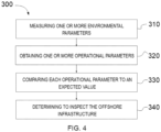
- a surveillance method for an offshore infrastructure comprises measuring, with an environmental sensor system of an unmanned surface vessel (USV), one or more environmental parameters and obtaining one or more operational parameters of the offshore infrastructure.
- the method further comprises comparing each of the operational parameters to an expected value and determining, based on the comparison, to inspect the offshore infrastructure with an unmanned vehicle.
- USV unmanned surface vessel
- the surveillance system 100 of figure 1 comprises a controller 20 arranged at the unmanned surface vessel. Communications between the environmental sensor system 40 and the controller 20 may thus be easily established. For example, the environmental sensor system may be wiredly connected to the controller. Communications between the controller and the unmanned vehicle may also be improved since the action radius of the unmanned vehicle is around the unmanned surface vessel.
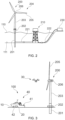
- Figure 2 schematically represents a plurality of offshore infrastructures suitable to be monitored by the surveillance system according to any of the examples herein disclosed.
- Figure 2 shows an offshore wind turbine 200 that generates electricity from the wind. Electricity generated by the offshore wind turbine 200 is conducted by a first underwater power cable 221 to an offshore electrical substation 210. Voltage received at the offshore electrical substation 210 is stepped up to a higher voltage. A second underwater power cable 222 connects the offshore electrical substation 210 to an onshore electrical substation 230 which is connected to the electrical grid.
- Several offshore wind turbines may be connected to a single offshore electrical substation through underwater power cables. The underwater offshore cables substantially lay on the seabed 111.
- the offshore electrical substation may be connected to another type of generation source, e.g. a tidal generator.
- the offshore infrastructure may comprise an offshore oil and gas equipment, e.g. an offshore oil and gas platform.
- the offshore wind turbine 200 also comprises a wind turbine controller, e.g. SCADA, that controls the operation of the wind turbine.
- the wind turbine may obtain a wind speed and may control the operation of the wind turbine, e.g. pitch angle and/or rotational speed, aiming to follow a specific power curve.
- the wind turbine operates following different power curves, each of them corresponding to a specific air density.
- the wind turbine controller may obtain the air density and may select a predetermined power curve corresponding to this specific air density.
- Sensors may be provided to measure the real power output.
- the real power output may be measured at a converter and/or a transformer arranged within the wind turbine.
- the wind turbine controller may also receive the real power output, e.g. from these sensors. Differences between the expected power output (according to the predetermined power curve) and the real power output may be indicative of a failure.
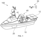
- FIG. 3 schematically represents a surveillance system according to an example of the present disclosure.
- the surveillance system of this figure may be according to any of the examples herein disclosed.
- the surveillance system 100 of figure 3 comprises an unmanned surface vessel 10 having an environmental sensor system 40 and a controller 20.
- the surveillance system 100 also comprises an unmanned vehicle 30 configured to inspect an offshore wind turbine 200.
- the unmanned vehicle 30 is an unmanned aerial vehicle.
- the surveillance system 100 is used to monitor the operation of the offshore wind turbine 200.
- the surveillance system of figure 3 may be employed to monitor other offshore infrastructures.
- the environmental sensor system 40 of figure 3 comprises a lidar 41, an ocean sensor and a camera. These sensors may be used to measure environmental parameters.
- the lidar 41 is configured to at least measure wind speed.
- the lidar is also configured to measure wind turbulence, wind direction and/or air density.
- the controller 20 obtains the wind speed from the lidar 41. From this wind speed, the controller may determine the expected power output of the offshore wind turbine. The controller may determine the expected power output from a predetermined power curve of the offshore wind turbine. The expected value, in this example the expected power output, may be determined based on the one or more environmental parameters, e.g. wind speed.
- the predetermined power curve of the offshore wind turbine may be stored in a non-transitory machine-readable storage medium of the controller.
- the offshore wind turbine manufacturer may provide one or more power curves to be stored in the non-transitory machine-readable storage medium.
- the controller 20 of this figure is configured to receive one or more operational parameters of the offshore wind turbine from the wind turbine controller 206.
- the wind turbine controller 206 and the controller 20 are wirelessly coupled.
- the wind turbine controller 206 may send one or more operational parameters to the controller 20.
- the wind turbine controller may send a pitch angle, a yaw angle and/or power output of the offshore wind turbine.
- the wind turbine controller may obtain these operational parameters according to any suitable method.
- the controller 20 is configured to receive the power output of the wind turbine. Then, the controller may compare the power output, i.e. the real power output, to the expected power output calculated from the wind speed measured with the lidar. Differences between the expected power output and the real power output may be indicative of a failure. The controller may determine to perform an inspection if the difference between the expected power output power and the real power output is higher than a predetermined power output difference ratio. This indicates that a potential failure or malfunctioning of the offshore wind turbine may occur.
- the predetermined power output difference ratio corresponds to the 10% of the expected power output. This is to say that an output power difference ratio higher than the 10% of the expected power output may indicate a potential failure or malfunction.
- the power output difference ratio may be 5% of the expected power output, specifically 1%. The predetermined power output ratio may be adjusted for different wind speeds.
- the controller is configured to compare the expected power output and the real power output during a period of time.
- the environmental sensor system may measure environmental parameters during a period of time, e.g. between 1 - 8 hours. These environmental parameters, e.g. wind speed, may be used to estimate the expected power output.
- the power output of the offshore wind turbine during this period of time may be compared to the expected power output. This may reduce the uncertainty of the measures. The risk of deciding to inspect the offshore wind turbine when not strictly required is minimized. If the controller determines that a potential failure or malfunctioning may occur, an inspection of the offshore wind turbine with the unmanned aerial vehicle may be determined. Otherwise, the controller may determine not to inspect the offshore wind turbine.
- the controller may instruct the unmanned surface vessel to travel towards another location, e.g. towards an offshore infrastructure.
- the controller is configured to continue monitoring the operation of the offshore wind turbine during a period of time. The controller may thus instruct the environmental sensor system to continue measuring the one or more environmental parameters. In this sense, accuracy of the decision may be increased.
- the controller may also take into account one or more environmental parameters to decide to perform the inspection. For example, if the environmental parameters are severe, the controller may determine not to inspect the offshore infrastructure to prevent damages on the unmanned vehicle. The controller may compare at least one of the one or more environmental parameters to a threshold. This comparison may also be taken into account for determining to inspect the offshore infrastructure. For example, the controller may compare the wind speed obtained from the lidar to a wind speed threshold. The wind speed threshold may be the maximum wind speed at which the unmanned aerial vehicle can fly. Additionally, or alternatively, the controller may compare the visibility to a visibility threshold to determine if the inspection is to be performed. If the visibility is lower than the visibility threshold, the unmanned aerial vehicle may not be able to obtain images or videos with a sufficient quality. The efficiency of the inspection may thus be increased if the visibility is taken into account.
- the unmanned aerial vehicle comprises a controller to determine a flight path towards the offshore wind turbine.
- the flight path may be defined by the controller of the surveillance system.
- the unmanned aerial vehicle 30 of this figure comprises a camera to take pictures or videos of selected parts of the offshore wind turbines.
- the unmanned aerial vehicle 30 may obtain images from the wind turbine blades 205, from the transition piece 202, from the tower 203 or from an above-water portion of the foundation 201.
- the unmanned aerial vehicle may also take pictures or videos from structural platforms (or parts of the structural platforms) arranged above the water.
- the unmanned vehicle is an unmanned aerial vehicle.
- the surveillance system may comprise an unmanned underwater vehicle.
- the unmanned underwater vehicle may perform inspections on the underwater portion of the foundation of the offshore wind turbine.
- An unmanned underwater vehicle may be configured to obtain images from an underwater portion of the foundation of the offshore wind turbine.
- the environmental sensor system comprises an ocean sensor to at least measure sea current speed and wherein the one or more environmental parameters comprises sea current speed and wherein the controller is further configured to compare the sea current speed to a sea current speed threshold. Determining to inspect the offshore wind turbine may also be based on the comparison of the sea current speed to the sea current speed threshold.
- the surveillance system comprises a plurality of unmanned vehicles, e.g. one or more unmanned aerial vehicles and one or more unmanned underwater vehicles.
- the controller may be configured to receive, from the unmanned vehicle, data about the inspection of the offshore infrastructure.
- the controller 20 may receive one or more images from the unmanned aerial vehicle 30. These images may be images of the selected parts of the wind turbine 200, e.g. a leading edge of the wind turbine blades 205.
- This data e.g. images from the wind turbine, may be analyzed to determine the status of the offshore infrastructure, e.g. to determine the status of a part of the offshore wind turbine.
- the controller 20 is configured to analyze data about the inspection of the offshore infrastructure, the offshore wind turbine 200 in this example. Analyze data about the inspection of the offshore infrastructure may comprise to compare this data to a predetermined pattern.
- the controller may be configured to compare images taken from the offshore wind turbine to a predetermined pattern.
- images of the leading edge of the wind turbine blade are compared to predetermined images stored in a storage medium.
- the predetermined pattern is one or more predetermined images showing surface defects or the degradation of the leading edge of wind turbine blades.
- the controller may compare the images obtained from the wind turbine blades to the predetermined pattern to determine if the leading edge has been degraded or has failures.
- An image recognition software may be used to identify a potential failure or degradation.
- a processor of the controller may execute this image recognition software. Artificial intelligence may be used for accurately comparing the images of the offshore infrastructure to the predetermined pattern.
- the controller is configured to also receive images from other offshore infrastructures, e.g. from other offshore wind turbines. These images may be stored in a storage medium to increase the database of images showing failures or defects. These may increase the number of predetermined patterns to compare the images taken from the offshore infrastructure. Accordingly, a failure may be more accurately determined.
- to analyze data about the inspection of the offshore infrastructure comprises to determine the status of the offshore wind turbine. The status indicates if a maintenance operation is required or if no defects have been detected.
- to determine the status of the offshore infrastructure comprises to perform a diagnosis of a cause of a failure. For example, if the controller detects a microcrack on a blade surface, the controller may determine which is the cause of this microcrack. Artificial intelligence and machine learning may be used to relate a specific failure to a predetermined cause of this failure. Predetermined images from other offshore infrastructure may be used to determine the failure and a potential cause of this failure. A look-up table may be used to relate predetermined images showing a defect and potential causes of this defect.
- the controller may be configured to determine the impact of the failure on the offshore infrastructure. For example, the controller may determine the impact on the power production and/or on the safety of the offshore wind turbine of the failure or defect. Depending on the impact of the failure, the controller may generate a maintenance plan and schedule maintenance tasks when required. For example, failures involving a relatively low impact on the offshore infrastructure, e.g. offshore wind turbine, may be corrected when other maintenance operations are to be performed. In this way, efficiency of the maintenance plan may be improved. Annual energy production may also be improved since corrective maintenance tasks may be scheduled together with other maintenance operations or when the offshore wind turbine is not operating.
- Analyzing data about the inspection of the offshore infrastructure may comprise sending an alarm to an onshore controller.
- the onshore controller or a maintenance operator may determine a maintenance plan to fix the detected failure or defect.
- the controller may generate a maintenance plan.
- the maintenance plan may include corrective maintenance tasks and/or preventive maintenance tasks. Corrective maintenance tasks may be performed to directly fix the failure or defect detected.
- Preventive maintenance task may be performed to maintain failures or defects under certain limits or to prevent that these failures could occur in other parts of the offshore infrastructure.
- Water quality may also be measured, since the water quality may for example indicate leakage of an underwater element, e.g. an underwater conduction or a degradation of an element of the offshore infrastructure.
- the one or more environmental parameters comprises a water quality and the one of the operational parameters of the offshore infrastructure may correspond to a leakage level or to degradation level of a part of the offshore infrastructure.
- An unmanned aerial vehicle may be used to inspect an electrical substation.
- the unmanned aerial vehicle may be equipped with a camera and/or an infrared sensor to for inspecting the temperature of the electrical substation.
- the environmental sensor system of the unmanned surface vessel may comprise a lidar to at least measure wind speed.
- the controller of the unmanned surface vessel may also be configured to compare the wind speed to a wind speed threshold according to any of the examples herein disclosed. In this example, determining to inspect the electrical substation is also based on the comparison of the wind speed to the wind speed threshold.
- An unmanned underwater vehicle may be used to inspect an underwater power cable.
- the unmanned underwater vehicle may comprise camera and/or an infrared sensor for inspecting the underwater power cable.
- Current speed may be compared to a current speed threshold and this comparison may also be taken into account for determining to inspect the underwater power cable.
- measuring, with an environmental sensor system of an unmanned surface vessel, one or more environmental parameters is represented.
- the one or more environmental parameters may be according to any of the examples herein described, e.g. wind speed.
- the environmental sensor system of the unmanned surface vessel may be suitable to measure the one or more environmental parameters.
- the method comprises positioning the unmanned surface vessel at a predetermined position.
- the unmanned surface vessel may be positioned at a distance of the offshore infrastructure. Distance of the unmanned vehicle for inspecting the offshore infrastructure may thus be reduced.
- communications between the offshore infrastructure and the controller of the surveillance system may thus be improved.
- wind speed measure for the environmental sensor system substantially correspond to the wind speed of the wind acting on the offshore wind turbine.
- the method further comprises sending an alarm to an onshore controller, e.g. an onshore controller not forming part of the surveillance system.
- the method may comprise generating a maintenance plan. This maintenance plan may be generated by the controller of the surveillance system, e.g. arranged at the unmanned surface vessel, or by an onshore controller of an onshore control center.
- the maintenance plan may contain a corrective and/or a preventive maintenance task.
Landscapes
- Engineering & Computer Science (AREA)
- Mechanical Engineering (AREA)
- Ocean & Marine Engineering (AREA)
- Remote Sensing (AREA)
- Aviation & Aerospace Engineering (AREA)
- Chemical & Material Sciences (AREA)
- Combustion & Propulsion (AREA)
- General Physics & Mathematics (AREA)
- Physics & Mathematics (AREA)
- Life Sciences & Earth Sciences (AREA)
- Atmospheric Sciences (AREA)
- Environmental & Geological Engineering (AREA)
- Radar, Positioning & Navigation (AREA)
- Automation & Control Theory (AREA)
- Transportation (AREA)
- Wind Motors (AREA)
Claims (15)
- Ein Überwachungssystem (100) für eine Offshore-Infrastruktur, umfassend:ein unbemanntes Fahrzeug (30) zum Prüfen der Offshore-Infrastruktur;ein unbemanntes Oberflächenschiff (USV, unmanned surface vessel) (10), umfassend:- ein Umweltsensorsystem (40), um einen oder mehrere Umweltparameter zu messen;- einen Tragebereich (12) zum Tragen des unbemannten Fahrzeugs (30); undeine Steuerung (20), die dazu konfiguriert ist:- den einen oder die mehreren Umweltparameter von dem Umweltsensorsystem (40) zu erhalten;dadurch gekennzeichnet, dass die Steuerung weiterhin dazu konfiguriert ist:- einen oder mehrere Betriebsparameter der Offshore-Infrastruktur zu erhalten;- jedes der Betriebsparameter mit einem erwarteten Wert zu vergleichen; und- auf Grundlage des Vergleichs zu bestimmen, die Offshore-Infrastruktur mit dem unbemannten Fahrzeug (30) zu prüfen.
- Ein Überwachungssystem (100) nach einem des Anspruchs 1, wobei die Steuerung (20) an dem unbemannten Oberflächenschiff (10) angeordnet ist.
- Ein Überwachungssystem (100) nach einem der Ansprüche 1 bis 2, wobei das Umgebungssensorsystem (40) ein Lidar (41), einen Ozeansensor, ein Sonar, einen Temperatursensor, einen Luftdichtesensor, einen Infrarotsensor und/oder eine Kamera umfasst.
- Ein Überwachungssystem (100) nach einem der Ansprüche 1 bis 3, wobei der eine oder die mehreren Umgebungsparameter mindestens eines von den Folgenden umfassen: Windgeschwindigkeit, Windrichtung, Windturbulenz, Luftdichte, Sichtbarkeit, Temperatur, Meeresströmungsgeschwindigkeit, Meeresströmungsrichtung, Wellenhöhe, Wellenrichtung, Wellenlänge, Meeressalzgehalt, Wasserqualität und Meeresspiegel.
- Ein Überwachungssystem (100) nach einem der Ansprüche 1 bis 4, wobei der eine oder die mehreren Betriebsparameter der Offshore-Infrastruktur Folgendes umfassen:den Leckagegrad der Offshore-Infrastruktur; und/oderden Degradationsgrad der Offshore-Infrastruktur; und/odereinen Nickwinkel einer Offshore-Windturbine (200), wenn die Offshore-Infrastruktur die Offshore-Windturbine (200) umfasst; und/oderden Gierwinkel einer Offshore-Windturbine (200), wenn die Offshore-Infrastruktur die Offshore-Windturbine (200) umfasst;eine Leistungsabgabe einer Offshore-Windturbine, wenn die Offshore-Infrastruktur die Offshore-Windturbine (200) umfasst; und/odereine Temperatur einer Offshore-Umspannstation, wenn die Offshore-Infrastruktur die Offshore-Umspannstation (210) umfasst; und/odereine Temperatur eines Seestromkabels, wenn die Offshore-Infrastruktur das Seestromkabel (221, 222) umfasst.
- Ein Überwachungssystem (100) nach einem der Ansprüche 1 bis 5, wobei die Steuerung (20) weiterhin dazu konfiguriert ist, mindestens einen des einen oder der mehreren Umgebungsparameter mit einem Schwellenwert zu vergleichen; und wobei das Bestimmen, die Offshore-Infrastruktur zu prüfen, weiterhin auf dem Vergleich des mindestens einen des einen oder der mehreren Umgebungsparameter mit dem Schwellenwert basiert.
- Ein Überwachungssystem (100) nach einem der Ansprüche 1 bis 6, wobei die Steuerung (20) weiterhin dazu konfiguriert ist, das Umgebungssensorsystem (40) anzuweisen, das Messen des einen oder der mehreren Umgebungsparameter fortzusetzen und/oder sich zu einem anderen Ort zu bewegen, wenn bestimmt wird, dass die Offshore-Infrastruktur nicht zu prüfen ist.
- Ein Überwachungssystem (100) nach einem der Ansprüche 1 bis 7, wobei die Steuerung (20) weiterhin dazu konfiguriert ist, das unbemannte Fahrzeug (30) anzuweisen, die Offshore-Infrastruktur zu prüfen, wenn bestimmt wird, dass die Offshore-Infrastruktur zu prüfen ist.
- Ein Überwachungssystem (100) nach Anspruch 8, wobei die Steuerung (20) weiterhin dazu konfiguriert ist, von dem unbemannten Fahrzeug (30) Daten über die Prüfung der Offshore-Infrastruktur zu empfangen.
- Ein Überwachungssystem (100) nach Anspruch 9, wobei die Steuerung (20) weiterhin dazu konfiguriert ist, die Daten über die Prüfung der Offshore-Infrastruktur an eine Onshore-Steuerung zu senden.
- Ein Überwachungssystem (100) nach einem der Ansprüche 1 bis 10, wobei die Offshore-Infrastruktur eine Offshore-Windturbine (200), eine Öl- und Gasausrüstung, eine elektrische Offshore-Umspannstation (210) und/oder ein Seestromkabel (221, 222) umfasst.
- Ein Überwachungsverfahren (300) für eine Offshore-Infrastruktur, umfassend:messen (310) eines oder mehrerer Umweltparameter mit einem Umweltsensorsystem (40) eines unbemannten Oberflächenschiffs (USV) (10);dadurch gekennzeichnet, dass das Verfahren (300) weiterhin Folgendes umfasst:erhalten (320) eines oder mehrerer Betriebsparameter der Offshore-Infrastruktur;vergleichen (330) jedes der Betriebsparameter mit einem erwarteten Wert; undbestimmen (340), auf Grundlage des Vergleichs, die Offshore-Infrastruktur mit einem unbemannten Fahrzeug (30) zu prüfen.
- Ein Überwachungsverfahren (300) nach Anspruch 12, weiterhin umfassend das Vergleichen von mindestens einem von dem einen oder den mehreren Umgebungsparametern mit einem Schwellenwert und wobei das Bestimmen, die Offshore-Infrastruktur zu prüfen, weiterhin auf dem Vergleich des mindestens einen von dem einen oder den mehreren Umgebungsparametern mit dem Schwellenwert basiert.
- Ein Überwachungsverfahren (300) nach einem der Ansprüche 12 bis 13, weiterhin umfassend das Bewegen des unbemannten Fahrzeugs (30) in Richtung zur Offshore-Infrastruktur, wenn bestimmt wird, die Offshore-Infrastruktur zu prüfen.
- Ein Überwachungsverfahren (300) nach Anspruch 14, weiterhin umfassend das Prüfen und das Erfassen von Daten über die Prüfung der Offshore-Infrastruktur mit dem unbemannten Fahrzeug (30).
Priority Applications (4)
| Application Number | Priority Date | Filing Date | Title |
|---|---|---|---|
| EP21383089.6A EP4190694B1 (de) | 2021-12-02 | 2021-12-02 | Überwachungssystem für eine offshore-infrastruktur |
| ES21383089T ES3038277T3 (en) | 2021-12-02 | 2021-12-02 | A surveillance system for an offshore infrastructure |
| PCT/EP2022/084243 WO2023099749A1 (en) | 2021-12-02 | 2022-12-02 | A surveillance system for an offshore infrastructure |
| US18/715,442 US20250036142A1 (en) | 2021-12-02 | 2022-12-02 | A surveillance system for an offshore infrastructure |
Applications Claiming Priority (1)
| Application Number | Priority Date | Filing Date | Title |
|---|---|---|---|
| EP21383089.6A EP4190694B1 (de) | 2021-12-02 | 2021-12-02 | Überwachungssystem für eine offshore-infrastruktur |
Publications (3)
| Publication Number | Publication Date |
|---|---|
| EP4190694A1 EP4190694A1 (de) | 2023-06-07 |
| EP4190694C0 EP4190694C0 (de) | 2025-07-02 |
| EP4190694B1 true EP4190694B1 (de) | 2025-07-02 |
Family
ID=78957133
Family Applications (1)
| Application Number | Title | Priority Date | Filing Date |
|---|---|---|---|
| EP21383089.6A Active EP4190694B1 (de) | 2021-12-02 | 2021-12-02 | Überwachungssystem für eine offshore-infrastruktur |
Country Status (4)
| Country | Link |
|---|---|
| US (1) | US20250036142A1 (de) |
| EP (1) | EP4190694B1 (de) |
| ES (1) | ES3038277T3 (de) |
| WO (1) | WO2023099749A1 (de) |
Families Citing this family (2)
| Publication number | Priority date | Publication date | Assignee | Title |
|---|---|---|---|---|
| NO347950B1 (en) * | 2023-09-12 | 2024-05-27 | Modi Vivendi As | Sound surveillance systems for critical offshore infrastructure |
| EP4600486A1 (de) * | 2024-02-12 | 2025-08-13 | Siemens Gamesa Renewable Energy A/S | Autonomes 3d-modellierungs- und anomaliedetektionssystem, offshore-anordnung und zugehörige verfahren |
Family Cites Families (6)
| Publication number | Priority date | Publication date | Assignee | Title |
|---|---|---|---|---|
| DK179018B1 (en) * | 2016-03-14 | 2017-08-21 | Ventus Eng Gmbh | Method of condition monitoring one or more wind turbines and parts thereof and performing instant alarm when needed |
| WO2018236903A1 (en) * | 2017-06-20 | 2018-12-27 | Planck Aerosystems Inc. | SYSTEMS AND METHODS FOR RECHARGING A PILOT-FREE AIR VEHICLE ON A MOBILE PLATFORM |
| US12283197B2 (en) * | 2019-07-10 | 2025-04-22 | Schlumberger Technology Corporation | Active learning for inspection tool |
| CN111776148B (zh) * | 2020-04-24 | 2022-06-24 | 上海交通大学 | 一种基于小型无人艇的海空潜一体化巡检系统 |
| CN112572707A (zh) * | 2020-12-29 | 2021-03-30 | 广东海洋大学 | 一种海上风电智能巡检系统 |
| CN113086137A (zh) * | 2021-04-14 | 2021-07-09 | 鹏城实验室 | 一种auv水面自主回收系统及回收方法 |
-
2021
- 2021-12-02 EP EP21383089.6A patent/EP4190694B1/de active Active
- 2021-12-02 ES ES21383089T patent/ES3038277T3/es active Active
-
2022
- 2022-12-02 US US18/715,442 patent/US20250036142A1/en active Pending
- 2022-12-02 WO PCT/EP2022/084243 patent/WO2023099749A1/en not_active Ceased
Also Published As
| Publication number | Publication date |
|---|---|
| WO2023099749A1 (en) | 2023-06-08 |
| US20250036142A1 (en) | 2025-01-30 |
| EP4190694C0 (de) | 2025-07-02 |
| EP4190694A1 (de) | 2023-06-07 |
| ES3038277T3 (en) | 2025-10-10 |
Similar Documents
| Publication | Publication Date | Title |
|---|---|---|
| JP5534248B2 (ja) | 無人浮流物質監視用ブイ、浮流物質監視システム及び浮流物質監視方法 | |
| JP7060501B2 (ja) | 風ベクトル場測定システム | |
| US20110148115A1 (en) | Deep offshore floating wind turbine and method of deep offshore floating wind turbine assembly, transportation, installation and operation | |
| US20250036142A1 (en) | A surveillance system for an offshore infrastructure | |
| CN111640220A (zh) | 一种用于海上风电场的无人船巡检系统及其工作方法 | |
| US20170363070A1 (en) | Methods and Systems of Maintaining an Offshore Power Plant | |
| US20170363069A1 (en) | Systems and Methods for Offshore Power Generation Using Airborne Power Generating Craft Tethered to a Floating Structure | |
| US20170363066A1 (en) | Methods and Systems for Electrical Isolation in an Offshore Power Generation Plant | |
| US20170363067A1 (en) | Methods and Systems for Maintaining an Offshore Power Plant Having Airborne Power Generating Craft | |
| CN118550259A (zh) | 一种智能化无人海洋监测网络系统及运行方法 | |
| Trslić et al. | Long term, inspection class ROV deployment approach for remote monitoring and inspection | |
| Niu et al. | Design, integration and sea trials of 3D printed unmanned aerial vehicle and unmanned surface vehicle for cooperative missions | |
| CN117644944A (zh) | 一种跨域协同海上风电运维无人系统及方法 | |
| KR20230117998A (ko) | 안전관리 및 유지보수 가능한 부유식 해상풍력발전단지 관제시스템 | |
| KR20230106901A (ko) | 자율운항 무인 이동체를 이용한 해상 풍력발전 단지 관리시스템 | |
| JP5002760B2 (ja) | 無人浮流物質監視用ブイ、浮流物質監視システム及び浮流物質監視方法 | |
| KR20250121035A (ko) | 무인 자율 기술을 이용하여 풍력 터빈을 검사하는 시스템 및 방법 | |
| Santos et al. | Developments in underwater robot capabilities for offshore wind | |
| Udvardy et al. | Inspection of wind power plant turbines by using UAV | |
| JP2023072596A (ja) | 無人点検システムおよび無人点検方法 | |
| EP4397586A1 (de) | Mehrzweckboje zur unterstützung eines projekts einer offshore-infrastruktur und offshore-infrastruktur | |
| JP7810019B2 (ja) | 点検装置 | |
| Zhang et al. | Energy consumption of a sailing quad-maran automated vessel | |
| US20250196973A1 (en) | Turbine Platform Current Energy Conversion System With Debris Protection | |
| CN115903056A (zh) | 轨条砦水空两栖无人航行器低频无源自主探测系统和方法 |
Legal Events
| Date | Code | Title | Description |
|---|---|---|---|
| PUAI | Public reference made under article 153(3) epc to a published international application that has entered the european phase |
Free format text: ORIGINAL CODE: 0009012 |
|
| STAA | Information on the status of an ep patent application or granted ep patent |
Free format text: STATUS: THE APPLICATION HAS BEEN PUBLISHED |
|
| AK | Designated contracting states |
Kind code of ref document: A1 Designated state(s): AL AT BE BG CH CY CZ DE DK EE ES FI FR GB GR HR HU IE IS IT LI LT LU LV MC MK MT NL NO PL PT RO RS SE SI SK SM TR |
|
| STAA | Information on the status of an ep patent application or granted ep patent |
Free format text: STATUS: REQUEST FOR EXAMINATION WAS MADE |
|
| 17P | Request for examination filed |
Effective date: 20231207 |
|
| RBV | Designated contracting states (corrected) |
Designated state(s): AL AT BE BG CH CY CZ DE DK EE ES FI FR GB GR HR HU IE IS IT LI LT LU LV MC MK MT NL NO PL PT RO RS SE SI SK SM TR |
|
| REG | Reference to a national code |
Ref country code: DE Ref legal event code: R079 Free format text: PREVIOUS MAIN CLASS: B64C0027080000 Ipc: B63B0081000000 Ref country code: DE Ref legal event code: R079 Ref document number: 602021033271 Country of ref document: DE Free format text: PREVIOUS MAIN CLASS: B64C0027080000 Ipc: B63B0081000000 |
|
| GRAP | Despatch of communication of intention to grant a patent |
Free format text: ORIGINAL CODE: EPIDOSNIGR1 |
|
| STAA | Information on the status of an ep patent application or granted ep patent |
Free format text: STATUS: GRANT OF PATENT IS INTENDED |
|
| RIC1 | Information provided on ipc code assigned before grant |
Ipc: B63B 35/00 20200101ALI20250110BHEP Ipc: B64U 101/30 20230101ALI20250110BHEP Ipc: B64U 101/26 20230101ALI20250110BHEP Ipc: B63B 35/44 20060101ALI20250110BHEP Ipc: B64U 80/84 20230101ALI20250110BHEP Ipc: B63B 81/00 20200101AFI20250110BHEP |
|
| INTG | Intention to grant announced |
Effective date: 20250204 |
|
| GRAS | Grant fee paid |
Free format text: ORIGINAL CODE: EPIDOSNIGR3 |
|
| GRAA | (expected) grant |
Free format text: ORIGINAL CODE: 0009210 |
|
| STAA | Information on the status of an ep patent application or granted ep patent |
Free format text: STATUS: THE PATENT HAS BEEN GRANTED |
|
| AK | Designated contracting states |
Kind code of ref document: B1 Designated state(s): AL AT BE BG CH CY CZ DE DK EE ES FI FR GB GR HR HU IE IS IT LI LT LU LV MC MK MT NL NO PL PT RO RS SE SI SK SM TR |
|
| REG | Reference to a national code |
Ref country code: GB Ref legal event code: FG4D |
|
| REG | Reference to a national code |
Ref country code: CH Ref legal event code: EP |
|
| REG | Reference to a national code |
Ref country code: DE Ref legal event code: R096 Ref document number: 602021033271 Country of ref document: DE |
|
| REG | Reference to a national code |
Ref country code: IE Ref legal event code: FG4D |
|
| U01 | Request for unitary effect filed |
Effective date: 20250715 |
|
| U07 | Unitary effect registered |
Designated state(s): AT BE BG DE DK EE FI FR IT LT LU LV MT NL PT RO SE SI Effective date: 20250721 |
|
| REG | Reference to a national code |
Ref country code: ES Ref legal event code: FG2A Ref document number: 3038277 Country of ref document: ES Kind code of ref document: T3 Effective date: 20251010 |
|
| U1O | Appointed representative for the unitary patent procedure deleted after the registration of the unitary effect | ||
| U1N | Appointed representative for the unitary patent procedure changed after the registration of the unitary effect |
Representative=s name: BARDEHLE PAGENBERG S.L.; ES |
|
| PG25 | Lapsed in a contracting state [announced via postgrant information from national office to epo] |
Ref country code: IS Free format text: LAPSE BECAUSE OF FAILURE TO SUBMIT A TRANSLATION OF THE DESCRIPTION OR TO PAY THE FEE WITHIN THE PRESCRIBED TIME-LIMIT Effective date: 20251102 |
|
| PGFP | Annual fee paid to national office [announced via postgrant information from national office to epo] |
Ref country code: GB Payment date: 20251229 Year of fee payment: 5 |
|
| PG25 | Lapsed in a contracting state [announced via postgrant information from national office to epo] |
Ref country code: NO Free format text: LAPSE BECAUSE OF FAILURE TO SUBMIT A TRANSLATION OF THE DESCRIPTION OR TO PAY THE FEE WITHIN THE PRESCRIBED TIME-LIMIT Effective date: 20251002 |
|
| PG25 | Lapsed in a contracting state [announced via postgrant information from national office to epo] |
Ref country code: HR Free format text: LAPSE BECAUSE OF FAILURE TO SUBMIT A TRANSLATION OF THE DESCRIPTION OR TO PAY THE FEE WITHIN THE PRESCRIBED TIME-LIMIT Effective date: 20250702 |
|
| PG25 | Lapsed in a contracting state [announced via postgrant information from national office to epo] |
Ref country code: GR Free format text: LAPSE BECAUSE OF FAILURE TO SUBMIT A TRANSLATION OF THE DESCRIPTION OR TO PAY THE FEE WITHIN THE PRESCRIBED TIME-LIMIT Effective date: 20251003 |
|
| PG25 | Lapsed in a contracting state [announced via postgrant information from national office to epo] |
Ref country code: CZ Free format text: LAPSE BECAUSE OF FAILURE TO SUBMIT A TRANSLATION OF THE DESCRIPTION OR TO PAY THE FEE WITHIN THE PRESCRIBED TIME-LIMIT Effective date: 20250702 |
|
| PG25 | Lapsed in a contracting state [announced via postgrant information from national office to epo] |
Ref country code: PL Free format text: LAPSE BECAUSE OF FAILURE TO SUBMIT A TRANSLATION OF THE DESCRIPTION OR TO PAY THE FEE WITHIN THE PRESCRIBED TIME-LIMIT Effective date: 20250702 |
|
| PG25 | Lapsed in a contracting state [announced via postgrant information from national office to epo] |
Ref country code: RS Free format text: LAPSE BECAUSE OF FAILURE TO SUBMIT A TRANSLATION OF THE DESCRIPTION OR TO PAY THE FEE WITHIN THE PRESCRIBED TIME-LIMIT Effective date: 20251002 |
|
| U20 | Renewal fee for the european patent with unitary effect paid |
Year of fee payment: 5 Effective date: 20251218 |