EP4190684A1 - Helm device - Google Patents
Helm device Download PDFInfo
- Publication number
- EP4190684A1 EP4190684A1 EP21850257.3A EP21850257A EP4190684A1 EP 4190684 A1 EP4190684 A1 EP 4190684A1 EP 21850257 A EP21850257 A EP 21850257A EP 4190684 A1 EP4190684 A1 EP 4190684A1
- Authority
- EP
- European Patent Office
- Prior art keywords
- housing
- tilt
- stopper
- steering shaft
- base
- Prior art date
- Legal status (The legal status is an assumption and is not a legal conclusion. Google has not performed a legal analysis and makes no representation as to the accuracy of the status listed.)
- Granted
Links
Images




Classifications
-
- B—PERFORMING OPERATIONS; TRANSPORTING
- B63—SHIPS OR OTHER WATERBORNE VESSELS; RELATED EQUIPMENT
- B63H—MARINE PROPULSION OR STEERING
- B63H20/00—Outboard propulsion units, e.g. outboard motors or Z-drives; Arrangements thereof on vessels
- B63H20/08—Means enabling movement of the position of the propulsion element, e.g. for trim, tilt or steering; Control of trim or tilt
- B63H20/10—Means enabling trim or tilt, or lifting of the propulsion element when an obstruction is hit; Control of trim or tilt
-
- B—PERFORMING OPERATIONS; TRANSPORTING
- B63—SHIPS OR OTHER WATERBORNE VESSELS; RELATED EQUIPMENT
- B63H—MARINE PROPULSION OR STEERING
- B63H25/00—Steering; Slowing-down otherwise than by use of propulsive elements; Dynamic anchoring, i.e. positioning vessels by means of main or auxiliary propulsive elements
- B63H25/02—Initiating means for steering, for slowing down, otherwise than by use of propulsive elements, or for dynamic anchoring
-
- B—PERFORMING OPERATIONS; TRANSPORTING
- B63—SHIPS OR OTHER WATERBORNE VESSELS; RELATED EQUIPMENT
- B63H—MARINE PROPULSION OR STEERING
- B63H20/00—Outboard propulsion units, e.g. outboard motors or Z-drives; Arrangements thereof on vessels
- B63H20/08—Means enabling movement of the position of the propulsion element, e.g. for trim, tilt or steering; Control of trim or tilt
- B63H20/12—Means enabling steering
-
- B—PERFORMING OPERATIONS; TRANSPORTING
- B63—SHIPS OR OTHER WATERBORNE VESSELS; RELATED EQUIPMENT
- B63H—MARINE PROPULSION OR STEERING
- B63H25/00—Steering; Slowing-down otherwise than by use of propulsive elements; Dynamic anchoring, i.e. positioning vessels by means of main or auxiliary propulsive elements
- B63H25/02—Initiating means for steering, for slowing down, otherwise than by use of propulsive elements, or for dynamic anchoring
- B63H2025/022—Steering wheels; Posts for steering wheels
Definitions
- the present invention relates to a helm device used to steer a boat.
- a steering device for changing the steering angle of an outboard motor a steering device which transmits the rotation of a steering shaft coupled to a steering wheel (helm) to an actuator of the outboard motor by a hydraulic pipe or a push-pull cable has been known.
- an electric steering device which detects the rotation of the steering shaft by a sensor and drives the actuator of the outboard motor on the basis of an electrical signal output by the sensor.
- the steering shaft is tilted at a predetermined tilt angle to a horizontal direction.
- the tilt angle of the helm device including the steering shaft should preferably be adjustable.
- a steering device disclosed in Patent Literature 1 has been known.
- Patent Literature 1 US 10,011,340 B2
- one of the objects of the present invention is to provide a helm device which can adjust the tilt angle of a steering shaft and which has excellent functionality and operability.
- a helm device comprises: a steering shaft extending in a first direction; a housing in which part of the steering shaft is housed; a tilt base mounted on a hull; a pair of tilt mechanisms which supports the housing to make the housing rotatable with respect to the tilt base about a tilt axis parallel to a second direction crossing the first direction; and a lock mechanism which fixes an angle of the steering shaft with respect to the tilt base by stopping the housing from being rotated by the pair of tilt mechanisms.
- Each of the pair of tilt mechanisms comprises: a shaft member projecting from a side portion of the housing crossing the tilt axis; a bracket provided on the tilt base and comprising a hole portion into which the shaft member is inserted rotatably; and a bushing disposed between an outer circumferential surface of the shaft member and an inner circumferential surface of the hole portion.
- the tilt base may comprise an opening, the housing may be passed through the opening, the bracket may project from the tilt base toward a front end portion of the steering shaft, and the tilt axis may be located between the tilt base and the front end portion of the steering shaft in the first direction.
- Each of the pair of tilt mechanisms may further comprise a first urging member which urges the housing in a predetermined rotation direction around the tilt axis.
- the first urging member may comprise a coil portion through which the shaft member is passed, an arm on a fixed-point side which extends from the coil portion and which is supported by the tilt base, and an arm on a point-of-action side which extends from the coil portion and which is supported by the housing.
- the lock mechanism may comprise: slots on an outer surface of the housing which are arranged in a circumferential direction around the tilt axis; and a lever comprising a latch which is insertable into the slots. In this case, when the latch is inserted into any one of the slots, the housing may be stopped from being rotated by the pair of tilt mechanisms.
- the lock mechanism may further comprise: a pin which couples the lever to the tilt base to make the lever rotatable about an axis parallel to the tilt axis; and a second urging member which urges the lever to press the latch against the slots.
- the second urging member may comprise a coil portion through which the pin is passed, an arm on a fixed-point side which extends from the coil portion and which is supported by the tilt base, and an arm on a point-of-action side which extends from the coil portion and which is supported by the lever.
- Each of the pair of tilt mechanisms may further comprise: a first stopper and a second stopper provided on the housing around the shaft member and arranged in a circumferential direction around the tilt axis; and a third stopper and a fourth stopper provided on the bracket and arranged concentrically with the first stopper and the second stopper.
- the first stopper and the third stopper may be brought into contact with each other and the housing may be stopped from further rotating in the first rotation direction
- the second stopper and the fourth stopper may be brought into contact with each other and the housing may be stopped from further rotating in the second rotation direction
- the lock mechanism may further comprise a fifth stopper and a sixth stopper located at ends of the slots in a circumferential direction around the tilt axis, respectively. Moreover, in a state where the latch is retracted from the slots, when the housing is rotated in a first rotation direction about the tilt axis and a tilt of the steering shaft thereby reaches a first critical angle, the fifth stopper and the latch may be brought into contact with each other and the housing may be stopped from further rotating in the first rotation direction, and in a state where the latch is retracted from the slots, when the housing is rotated in a second rotation direction opposite to the first rotation direction and the tilt of the steering shaft thereby reaches a second critical angle, the sixth stopper and the latch may be brought into contact with each other and the housing may be stopped from further rotating in the second rotation direction.
- An end portion of the steering shaft located inside the housing may overlap the shaft member in a direction parallel to the tilt axis.
- the helm device may further comprise an electromagnetic brake which is housed in the housing and which gives resistance to the steering shaft.
- the housing may comprise a front end portion through which the steering shaft extends and a back end portion located opposite to the front end portion in the first direction. Moreover, the shaft member may be located closer to the back end portion than the electromagnetic brake in the first direction.
- the helm device may further comprise: a first circuit board on which a sensor is mounted, the sensor detecting rotation of the steering shaft; and a second circuit board on which a power supply circuit is mounted, the power supply circuit supplying power to the first circuit board.
- the first circuit board may overlap the shaft member in the second direction, and the second circuit board may be located between the first circuit board and the back end portion in the first direction.
- the housing may comprise: a housing base comprising a first end portion in the first direction, a second end portion opposite to the first end portion, and the shaft member of each of the pair of tilt mechanisms; a housing top coupled to the first end portion of the housing base and provided with an opening through which the steering shaft is passed; and a cover coupled to the second end portion of the housing base.
- the housing base and the housing top may form a first chamber in which part of the steering shaft and the electromagnetic brake are housed
- the housing base and the cover may form a second chamber in which the first circuit board and the second circuit board are housed
- the second chamber may overlap the shaft member in the second direction.
- the present invention can provide a helm device which can adjust the tilt angle of a steering shaft and which has excellent functionality and operability.
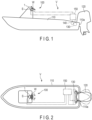
- FIG. 1 is a schematic side view of a boat V on which a steering device is mounted according to the present embodiment.
- FIG. 2 is a schematic plan view of the boat V shown in FIG. 1 .
- the boat V comprises a steering device 100, a hull 110, and an outboard motor 120.
- the steering device 100 comprises a helm device 1 comprising a steering wheel W and a sensor S for detecting the amount of rotation (steering angle) of the steering wheel W, an electric actuator 130 which changes the steering angle of the outboard motor 120, a steering angle sensor 140 which detects the steering angle of the outboard motor 120, and a control unit 150.
- the control unit 150 is electrically connected to the helm device 1, the actuator 130, and the steering angle sensor 140.
- the outboard motor 120 comprises a screw which gives propulsive power to the boat V and is mounted on, for example, a rear wall 110a of the hull 110.
- the control unit 150 drives the actuator 130 to make a target steering angle set on the basis of information acquired from the sensor S and the actual steering angle of the outboard motor 120 detected by the steering angle sensor 140 agree with each other.
- FIG. 3 is a schematic perspective view of the helm device 1.
- the helm device 1 comprises a steering shaft 2, a housing 3, a tilt base 4, a pair of tilt mechanisms 5R and 5L, and a lock mechanism 6.
- the steering shaft 2 has a shape long in a first direction X and comprises a mounting portion 20 on which the steering wheel W is mounted in the vicinity of a front end portion 2a. Part of the steering shaft 2 is housed in the housing 3.
- the steering shaft 2 is rotatable about a shaft axis SX parallel to the first direction X.
- the housing 3 comprises a front end portion 3a in the first direction X and a back end portion 3b opposite to the front end portion 3a.
- the steering shaft 2 extends through the front end portion 3a.
- the housing 3 is composed of a housing base 30, a housing top 31 including the front end portion 3a, and a cover 32 including the back end portion 3b.
- the housing base 30 and the housing top 31 are formed of metallic materials and the cover 32 is formed of a resin material.
- the housing base 30 is, for example, cylindrical and comprises a first end portion 30a in the first direction X and a second end portion 30b opposite to the first end portion 30a.
- the housing top 31 is coupled to the first end portion 30a by coupling members 33 which are, for example, bolts.
- the cover 32 is coupled to the second end portion 30b by coupling members which are, for example, bolts.
- the housing top 31 comprises an opening 31a for passing the steering shaft 2 at the front end portion 3a.
- the gap between the inner wall of the opening 31a and the steering shaft 2 is closed by a lid member 31b.
- the tilt base 4 comprises a first side surface 4a in the first direction X, a second side surface 4b opposite to the first side surface 4a, and an opening 4c reaching from the first side surface 4a to the second side surface 4b.
- the housing 3 is passed through the opening 4c.
- Most of the housing 3 is located closer to the front end portion 2a of the steering shaft 2 than the first side surface 4a.
- the tilt base 4 is fixed at the mounting position by an appropriate means such as fastening by bolts.
- the tilt mechanisms 5R and 5L support the housing 3 to make the housing 3 rotatable with respect to the tilt base 4 about a tilt axis TX parallel to a second direction Y crossing the first direction X.
- the first direction X and the second direction Y are orthogonal.
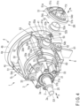
- FIG. 4 is a schematic perspective view of the helm device 1 in a state where the tilt mechanism 5R is disassembled.
- the tilt mechanism 5R comprises a shaft member 50, a bracket 51, a bushing 52, and a first urging member 53.
- the shaft member 50 is provided at a side portion of the housing 3 (side portion of the housing base 30) which crosses the tilt axis TX.
- the shaft member 50 comprises a cylindrical first portion 50a having its center on the tilt axis TX and a circular second portion 50b having its center on the tilt axis TX.
- the diameter of the outer circumferential surface of the second portion 50b is larger than the diameter of the outer circumferential surface of the first portion 50a.
- the second portion 50b is located between the first portion 50a and the housing base 30.
- the first portion 50a and the second portion 50b are formed integrally with the housing base 30.
- the first portion 50a and the second portion 50b may be coupled to the housing base 30 by an appropriate means such as screwing.
- the bracket 51 comprises a mounting surface 51a on the tilt base 4 side and a circular hole portion 51b having its center on the tilt axis TX.
- the hole portion 51b is an opening which penetrates the bracket 51 in the second direction Y, but the hole portion 51b may be a recess having a bottom.
- the inside diameter of the hole portion 51b is larger than the outside diameter of the first portion 50a of the shaft member 50.
- the tilt base 4 comprises a base portion 41 on the first side surface 4a side.
- the base portion 41 is provided with a pair of mounting holes 41a which penetrates to the second side surface 4b.
- female screws 51c are provided at positions facing the mounting holes 41a.
- the bracket 51 is coupled to the tilt base 4 by bringing the mounting surface 51a into contact with the base portion 41 and screwing bolts into the female screws 51c through the mounting holes 41a, respectively.
- the bushing 52 comprises a cylindrical first portion 52a having its center on the tilt axis TX and a cylindrical second portion 52b similarly having its center on the tilt axis TX.
- the inside diameter of the first portion 52a is larger than the outside diameter of the first portion 50a of the shaft member 50, and the outside diameter of the first portion 52a is smaller than the inside diameter of the hole portion 51b of the bracket 51.
- the outside diameter of the second portion 52b is larger than the inside diameter of the hole portion 51b.
- a first stopper 54a and a second stopper 54b projecting in the second direction Y are provided on the outer surface of the housing base 30.
- the first stopper 54a and the second stopper 54b are arranged in a circumferential direction having its center on the tilt axis TX.
- a gap is provided between the first and second stoppers 54a and 54b and the second portion 50b of the shaft member 50.
- a third stopper 54c and a fourth stopper 54d projecting in the second direction Y are provided on a surface facing the housing base 30 of the bracket 51. In a state where the tilt mechanism 5R is assembled, the third stopper 54c and the fourth stopper 54d are arranged concentrically with the first stopper 54a and the second stopper 54b.
- the first urging member 53 is, for example, a torsion spring and comprises a coil portion 53a which is a spirally wound wire and a pair of arms 53b and 53c which extends from the coil portion 53a.
- the shaft member 50 is passed through the coil portion 53a.
- the coil portion 53a is located between the second portion 50b and the stoppers 54a and 54b.
- the arm 53b is held by a holding portion 42 provided on the tilt base 4.
- the arm 53c contacts the lower surface (surface on the shaft member 50 side) of the first stopper 54a.
- the portion held by the holding portion 42 of the arm 53b corresponds to a fixed point of the first urging member 53.
- the portion which contacts the first stopper 54a of the arm 53c corresponds to a point of action of the first urging member 53.
- the first portion 50a of the shaft member 50 is inserted into the bushing 52, and the first portion 52a of the bushing 52 is inserted into the hole portion 51b of the bracket 51.
- the first portion 52a of the bushing 52 is interposed between the first portion 50a of the shaft member 50 and the inner wall of the hole portion 51b.
- the second portion 52b of the bushing 52 is interposed between the second portion 50b of the shaft member 50 and the peripheral portion of the hole portion 51b of the bracket 51.
- the tilt mechanism 5L has the same structure as the tilt mechanism 5R. Accordingly, the housing 3 is supported by the tilt mechanisms 5R and 5L and is rotatable about the tilt axis TX with respect to the tilt base 4.
- each of the brackets 51 projects from the tilt base 4 toward the front end portion 2a of the steering shaft 2.
- the tilt axis TX is located between the tilt base 4 and the front end portion 2a of the steering shaft 2.
- the center of gravity of the main body of the helm device 1 including the steering shaft 2 and the housing 3, which is supported by the tilt mechanisms 5R and 5L, is located closer to the front end portion 2a of the steering shaft 2 than the tilt axis TX.
- the housing 3 can rotate to cause the shaft axis SX to point downward in FIG. 3 and FIG. 4 .
- the first urging member 53 has the function of restraining such rotation. That is, the first urging member 53 urges the housing 3 to cause the shaft axis SX to point upward in FIG. 3 and FIG. 4 .
- FIG. 5 is a schematic partial cross-sectional view of the helm device 1 along line V-V in FIG. 3 .
- the structure of the lock mechanism 6 will be described hereinafter with reference to FIG. 3 and FIG. 5 .
- the lock mechanism 6 comprises an arcuate portion 60 provided at the lower part of the housing 3, a lever 61, a pin 62, and a second urging member 63.
- the arcuate portion 60 is, for example, formed integrally with the housing base 30, and has an arcuate outer circumferential surface having its center on the tilt axis TX.
- the outer circumferential surface is provided with slots 64 (grooves).
- the slots 64 extend parallel to the tilt axis TX and are arranged at regular intervals in a circumferential direction having its center on the tilt axis TX.
- the arcuate portion 60 comprises the five slots 64, but the number of slots 64 may be four or less or may be six or greater.
- the tilt base 4 comprises a pair of holding portions 65R and 65L for holding the lever 61.
- the holding portion 65R is shown in FIG. 3 and the holding portion 65L is shown in FIG. 5 .
- the shapes of the holding portions 65R and 65L are the same, and both of them project from the first side surface 4a in the lower part of the tilt base 4.
- the lever 61 is made of, for example, metal and is located between the holding portions 65R and 65L.
- the pin 62 is parallel to the tilt axis TX and is passed through each hole provided in the holding portions 65R and 65L and the lever 61.
- the lever 61 is thereby coupled to the tilt base 4 to be rotatable about an axis parallel to the tilt axis TX.
- the lever 61 comprises an operation portion 61a extending downward from the vicinity of the pin 62 and an action portion 61b extending toward the arcuate portion 60 from the vicinity of the pin 62.
- the operation portion 61a and the action portion 61b form a substantially L-shape.
- the operation portion 61a is a portion for a user to operate (push) by hand.
- a latch 61c which is insertable into and removable from the slots 64 is provided.
- the operation portion 61a may be covered by a cover formed of, for example, resin or rubber. Such a cover may be attachable to and detachable from the operation portion 61a.
- the second urging member 63 is, for example, a torsion spring and comprises a pair of coil portions 63Ra and 63La which is spirally wound wires, an arm 63b extending from the coil portions 63Ra and 63La and connecting the coil portions 63Ra and 63La, and arms 63c extending from the coil portions 63Ra and 63La, respectively.
- the coil portion 63Ra is shown in FIG. 3 and the coil portion 63La is shown in FIG. 5 .
- the pin 62 is passed through the coil portions 63Ra and 63La.
- the arm 63b is supported by a support portion 43 provided on the tilt base 4.
- the arms 63c extending from the coil portions 63Ra and 63La, respectively, contact the back surface of the operation portion 61a.
- the portion supported by the support portion 43 of the arm 63b corresponds to a fixed point of the second urging member 63.
- the portion which contacts the back surface of the operation portion 61a of each of the arms 63c corresponds to a point of action of the second urging member 63.
- the second urging member 63 always urges the lever 61 to press the latch 61c against the arcuate portion 60.
- the latch 61c keeps being inserted into the slots 64 as shown in FIG. 5 .
- the rotation of the housing 3 by the tilt mechanisms 5R and 5L is prevented.
- FIG. 6 is a schematic cross-sectional view of the helm device 1 along line VI-VI in FIG. 3 .
- FIG. 7 is a schematic cross-sectional view of a state where the housing 3 is disassembled in the helm device 1 shown in FIG. 6 .
- the first end portion 30a of the housing base 30 is inserted into the inside of the housing top 31.
- part of the cover 32 is inserted into the inside of the second end portion 30b of the housing base 30.
- the housing base 30 comprises a partition portion 34 in its inside.
- the partition portion 34 partitions the inside of the housing 3 into a first chamber C1 and a second chamber C2.
- the first chamber C1 is a space formed by the housing base 30 and the housing top 31.
- the second chamber C2 is a space formed by the housing base 30 and the cover 32.
- the partition portion 34 comprises an opening 34a.
- the steering shaft 2 is passed through the opening 31a of the housing top 31 and the opening 34a of the partition portion 34.
- a back end portion 2b of the steering shaft 2, which is located inside the housing 3, is provided with a magnet 21.
- the back end portion 2b and the magnet 21 are covered by a cover 22.
- the cover 22 is, for example, coupled to the partition portion 34 by coupling members 23 which are, for example, screws.
- the steering shaft 2 is rotatably supported by a bearing member 24 provided at the opening 31a and a bearing member 25 provided at the opening 34a.
- an elastic member 26 which is, for example, a Belleville spring is disposed in the first chamber C1.
- the steering shaft 2 is urged by the elastic member 26 in a direction in which it projects from the housing 3 (left in FIG. 6 and FIG. 7 ).
- the elastic member 26 deforms when receiving a load in a direction along an axial line of the steering shaft 2, and thus also has the function of absorbing vibration in this direction.
- the electromagnetic brake 7 comprises a rotation member 70, an electromagnet 71, an armature 72, and a disk group 73.
- the rotation member 70 is fixed to the steering shaft 2 and rotates with the steering shaft 2.
- the electromagnet 71 is fixed to the inside of the housing base 30 around the steering shaft 2.
- the armature 72 is disposed around the steering shaft 2 inside the housing top 31.
- the armature 72 is movable in the first direction X with respect to the steering shaft 2.
- the electromagnet 71 and the armature 72 are opposed in the first direction X.
- the disk group 73 includes rotating disks and fixed disks. Tooth portions are formed on the inner circumferential portions of the rotating disks, and the tooth portions are fitted into splines formed on the outer circumferential surface of the rotation member 70. The rotating disks are thereby held by the rotation member 70 to be movable in the first direction X and rotate with the rotation member 70. Tooth portions are formed on the outer circumferential portions of the fixed disks, and the tooth portions are fitted into splines provided on a yoke of the electromagnet 71. The fixed disks are thereby held by the yoke to be movable in the first direction X and to be nonrotatable with respect to the housing top 31. The rotating disks and the fixed disks are alternately arranged in the first direction X between the electromagnet 71 and the armature 72.
- the electromagnet 71 includes the above yoke and a coil. By magnetic force produced when the coil is supplied with power, the armature 72 is attracted to the yoke and the disk group 73 is pushed. At this time, in the disk group 73, the rotating disks and the fixed disks are pressed against each other, increasing friction force at the time when the steering shaft 2 is rotated.
- the electromagnetic brake 7 like this can adjust resistance (steering effort) at the time when the steering shaft 2 and the steering wheel W are operated.
- the resistance is set by the control unit 150 in accordance with the boat operator's request or the conditions under which the boat is operated. To increase the resistance, power supplied to the coil of the electromagnet 71 should be increased, and to decrease the resistance, the power should be decreased.
- the control unit 150 may has the function of locking the steering shaft 2 to prevent the steering wheel W from further rotating when the steering wheel W has rotated from the neutral position to the maximum steering angle. That is, when the steering wheel W has rotated to the starboard side or the port side up to the maximum number of steering wheel rotations, the control unit 150 maximizes power supplied to the electromagnet 71. Consequently, the magnetic force of the electromagnet 71 is maximized, and the rotating disks and the fixed disks in the disk group 73 are locked together.
- a first circuit board 81 and a second circuit board 82 in the form of flat plates orthogonal to the first direction X are disposed.
- the first circuit board 81 is fixed to boss portions 35 provided on the partition portion 34 by coupling members 36 which are, for example, screws.
- the second circuit board 82 is fixed to boss portions 37 provided on the cover 32 by coupling members 38 which are, for example, screws.
- the first circuit board 81 and the second circuit board 82 are opposed with a gap therebetween in the first direction X.
- the above-described sensor S is mounted on the first circuit board 81.
- the sensor S detects the rotation of the steering shaft 2 on the basis of magnetism produced by the magnet 21.
- a power supply circuit 83 which supplies power to the electrical elements of the helm device 1, such as the first circuit board 81, the electromagnetic brake 7, and the sensor S, is mounted.
- the electromagnetic brake 7 and the power supply circuit 83, and the first circuit board 81 and the second circuit board 82 are connected by lines not shown in the figure.
- lines not shown in the figure for connecting to devices such as the control unit 150 and a battery which are disposed outside the housing 3 are connected to the first circuit board 81 and the second circuit board 82.
- the two circuit boards 81 and 82 are disposed in the housing 3, the space for mounting various ICs and electronic components including the sensor S and the power supply circuit 83 can be secured widely. Moreover, if the circuit boards 81 and 82 are arranged in the first direction X, the widths in the second direction Y of the circuit boards 81 and 82, the second chamber C2, the housing 3, etc., can be made small.
- the tilt axis TX is disposed at a position closer to the back end portion 3b than to the front end portion 3a of the housing 3.
- the back end portion 2b of the steering shaft 2 located inside the housing 3 overlaps each of the shaft members 50.
- the second chamber C2 and the first circuit board 81 also overlap each of the shaft members 50 in the second direction Y.
- the tilt axis TX extends through the space between the first circuit board 81 and the partition portion 34.
- the sensor S and the magnet 21 are located substantially on the tilt axis TX.
- the first chamber C1 is located closer to the front end portion 3a of the housing 3 than the tilt axis TX.
- each of the shaft members 50 is located closer to the back end portion 3b of the housing 3 than the electromagnetic brake 7.
- the second circuit board 82 does not overlap each of the shaft members 50 in the second direction Y and is located closer to the back end portion 3b than the first circuit board 81.
- the present embodiment can provide the helm device 1, which can adjust the tilt angle of the steering shaft 2 and has excellent functionality and operability.
- the specific action and effects of the helm device 1 will be explained.
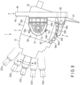
- FIG. 8 is a schematic side view of the helm device 1.
- the five slots 64 of the lock mechanism 6 will be hereinafter referred to as slots 64a, 64b, 64c, 64d, and 64e as shown in FIG. 8 .
- the latch 61c is inserted into the central slot 64c.
- the steering shaft 2 and the housing 3 can be rotated by the tilt mechanisms 5R and 5L on the tilt axis TX in a first rotation direction R1 and a second rotation direction R2 opposite to the first rotation direction R1.
- the rotation by the tilt mechanisms 5R and 5L can be locked by inserting the latch 61c into any one of the slots 64a, 64b, 64c, 64d, and 64e.
- shaft axes SX when the latch 61c is inserted into the slots 64a, 64b, 64c, 64d, and 64e, respectively, will be hereinafter referred to as shaft axes SXa, SXb, SXc, SXd, and SXe.
- the shaft axis SXc is defined as a reference position of the steering shaft 2. Moreover, the angles formed by the shaft axes SXa, SXb, SXd, and SXe with respect to the shaft axis SXc are defined as tilt angles.
- the tilt angles correspond to the tilts of the steering shaft 2.
- the tilt angle of the shaft axis SXa corresponds to a first critical angle which can be set in the first rotation direction R1
- the tilt angle of the shaft axis SXe corresponds to a second critical angle which can be set in the second rotation direction R2.
- the tilt angle of the shaft axis SXa is +24°
- the tilt angle of the shaft axis SXb is +12°
- the tilt angle of the shaft axis SXd is -12°
- the tilt angle of the shaft axis SXe is -24°.
- the respective tilt angles of the shaft axes SXa, SXb, SXd, and SXe are not limited to this example.
- the tilt angles are not necessarily adjustable at equal angles (12° in the above example).
- the housing 3 when the housing 3 is rotated in the second rotation direction R2 and the tilt angle thereby reaches -24° (second critical angle), which corresponds to the slot 64e, the second stopper 54b and the fourth stopper 54d are brought into contact with each other. The housing 3 is thereby stopped from further rotating in the second rotation direction R2. Note that at least in a state where the tilt angle is in the range between the first critical angle and the second critical angle, the housing 3 does not contact the tilt base 4.
- second critical angle second critical angle
- the rotation of the housing 3 is stopped at the positions corresponding to the slots 64a and 64e, and the boat operator thereby can easily know the limit of tilt angle adjustment.
- the housing 3 is not rotated beyond the first critical angle or the second critical angle, a collision of the tilt base 4 and the hull with the housing 3 can be prevented.
- the first stopper 54a also has the function of receiving the arm 53c of the first urging member 53, as well as the function of stopping the housing 3 from further rotating in the first rotation direction R1 at the first critical angle. Accordingly, the structural elements of the helm device 1 can be reduced and the assembly of the helm device 1 is facilitated.
- the above-described first urging member 53 prevents the steering shaft 2 from tilting downward because of the weight of the housing 3, etc., in a state where the fixing of the housing 3 by the lock mechanism 6 is released.
- the tilt axis TX is located between the tilt base 4 and the front end portion 2a of the steering shaft 2 in the first direction X. Furthermore, the tilt axis TX is located at a position closer to the back end portion 3b than to the front end portion 3a of the housing 3 in the first direction X. These reduce the amount by which the housing 3 projects more backward than the tilt base 4 and increase the degree of freedom of the structure of the hull to which the tilt base 4 is fixed.
- the present embodiment does not limit the scope of the present invention to the structure disclosed in the present embodiment.
- the present invention can be carried out by modifying the structure disclosed in the present embodiment into various forms.
- a means (stopper structure) for stopping the rotation of the housing 3 at the first critical angle and the second critical angle is not limited to the stoppers 54a, 54b, 54c, and 54d.
- FIG. 9 is a schematic side view of the helm device 1 according to a modified example.
- the lock mechanism 6 comprises a fifth stopper 66a and a sixth stopper 66b.
- the helm device 1 may further comprise the above-described stoppers 54a, 54b, 54c, and 54d in addition to the fifth stopper 66a and the sixth stopper 66b.
- the fifth stopper 66a and the sixth stopper 66b are located at both ends of the slots 64a, 64b, 64c, 64d, and 64e, respectively, in a circumferential direction having its center on the tilt axis TX.
- the fifth stopper 66a and the sixth stopper 66b project downward sufficiently longer than the portions between the slots 64a, 64b, 64c, 64d, and 64e of the arcuate portion 60.
- the fifth stopper 66a and the sixth stopper 66b have such a length that they contact the latch 61c when the housing 3 is rotated about the tilt axis TX even in a state where the lever 61 is pushed to move the latch 61c farthest away from the arcuate portion 60.
- the fifth stopper 66a and the sixth stopper 66b as described above also can stop the housing 3 from rotating beyond the first critical angle and the second critical angle.
Landscapes
- Chemical & Material Sciences (AREA)
- Engineering & Computer Science (AREA)
- Combustion & Propulsion (AREA)
- Mechanical Engineering (AREA)
- Ocean & Marine Engineering (AREA)
- Steering Controls (AREA)
Abstract
Description
- The present invention relates to a helm device used to steer a boat.
- Conventionally, as a steering device for changing the steering angle of an outboard motor, a steering device which transmits the rotation of a steering shaft coupled to a steering wheel (helm) to an actuator of the outboard motor by a hydraulic pipe or a push-pull cable has been known. In addition, there is also an electric steering device which detects the rotation of the steering shaft by a sensor and drives the actuator of the outboard motor on the basis of an electrical signal output by the sensor.
- In general, the steering shaft is tilted at a predetermined tilt angle to a horizontal direction. To achieve comfortable operability for a boat operator, the tilt angle of the helm device including the steering shaft should preferably be adjustable. For example, as a prior art which enables such adjustment, a steering device disclosed in
Patent Literature 1 has been known. - Patent Literature 1:
US 10,011,340 B2 - There's room for various improvements in the functionality and operability of a conventional helm device which can adjust the tilt angle of a steering shaft including the structure disclosed in
Patent Literature 1. Thus, one of the objects of the present invention is to provide a helm device which can adjust the tilt angle of a steering shaft and which has excellent functionality and operability. - According to an embodiment, a helm device comprises: a steering shaft extending in a first direction; a housing in which part of the steering shaft is housed; a tilt base mounted on a hull; a pair of tilt mechanisms which supports the housing to make the housing rotatable with respect to the tilt base about a tilt axis parallel to a second direction crossing the first direction; and a lock mechanism which fixes an angle of the steering shaft with respect to the tilt base by stopping the housing from being rotated by the pair of tilt mechanisms. Each of the pair of tilt mechanisms comprises: a shaft member projecting from a side portion of the housing crossing the tilt axis; a bracket provided on the tilt base and comprising a hole portion into which the shaft member is inserted rotatably; and a bushing disposed between an outer circumferential surface of the shaft member and an inner circumferential surface of the hole portion.
- The tilt base may comprise an opening, the housing may be passed through the opening, the bracket may project from the tilt base toward a front end portion of the steering shaft, and the tilt axis may be located between the tilt base and the front end portion of the steering shaft in the first direction.
- Each of the pair of tilt mechanisms may further comprise a first urging member which urges the housing in a predetermined rotation direction around the tilt axis. In this case, the first urging member may comprise a coil portion through which the shaft member is passed, an arm on a fixed-point side which extends from the coil portion and which is supported by the tilt base, and an arm on a point-of-action side which extends from the coil portion and which is supported by the housing.
- The lock mechanism may comprise: slots on an outer surface of the housing which are arranged in a circumferential direction around the tilt axis; and a lever comprising a latch which is insertable into the slots. In this case, when the latch is inserted into any one of the slots, the housing may be stopped from being rotated by the pair of tilt mechanisms.
- The lock mechanism may further comprise: a pin which couples the lever to the tilt base to make the lever rotatable about an axis parallel to the tilt axis; and a second urging member which urges the lever to press the latch against the slots. In this case, the second urging member may comprise a coil portion through which the pin is passed, an arm on a fixed-point side which extends from the coil portion and which is supported by the tilt base, and an arm on a point-of-action side which extends from the coil portion and which is supported by the lever.
- Each of the pair of tilt mechanisms may further comprise: a first stopper and a second stopper provided on the housing around the shaft member and arranged in a circumferential direction around the tilt axis; and a third stopper and a fourth stopper provided on the bracket and arranged concentrically with the first stopper and the second stopper. Moreover, when the housing is rotated in a first rotation direction around the tilt axis and a tilt of the steering shaft thereby reaches a first critical angle, the first stopper and the third stopper may be brought into contact with each other and the housing may be stopped from further rotating in the first rotation direction, and when the housing is rotated in a second rotation direction opposite to the first rotation direction and the tilt of the steering shaft thereby reaches a second critical angle, the second stopper and the fourth stopper may be brought into contact with each other and the housing may be stopped from further rotating in the second rotation direction.
- The lock mechanism may further comprise a fifth stopper and a sixth stopper located at ends of the slots in a circumferential direction around the tilt axis, respectively. Moreover, in a state where the latch is retracted from the slots, when the housing is rotated in a first rotation direction about the tilt axis and a tilt of the steering shaft thereby reaches a first critical angle, the fifth stopper and the latch may be brought into contact with each other and the housing may be stopped from further rotating in the first rotation direction, and in a state where the latch is retracted from the slots, when the housing is rotated in a second rotation direction opposite to the first rotation direction and the tilt of the steering shaft thereby reaches a second critical angle, the sixth stopper and the latch may be brought into contact with each other and the housing may be stopped from further rotating in the second rotation direction.
- An end portion of the steering shaft located inside the housing may overlap the shaft member in a direction parallel to the tilt axis.
- The helm device may further comprise an electromagnetic brake which is housed in the housing and which gives resistance to the steering shaft.
- The housing may comprise a front end portion through which the steering shaft extends and a back end portion located opposite to the front end portion in the first direction. Moreover, the shaft member may be located closer to the back end portion than the electromagnetic brake in the first direction.
- The helm device may further comprise: a first circuit board on which a sensor is mounted, the sensor detecting rotation of the steering shaft; and a second circuit board on which a power supply circuit is mounted, the power supply circuit supplying power to the first circuit board. Moreover, the first circuit board may overlap the shaft member in the second direction, and the second circuit board may be located between the first circuit board and the back end portion in the first direction.
- The housing may comprise: a housing base comprising a first end portion in the first direction, a second end portion opposite to the first end portion, and the shaft member of each of the pair of tilt mechanisms; a housing top coupled to the first end portion of the housing base and provided with an opening through which the steering shaft is passed; and a cover coupled to the second end portion of the housing base. In this case, the housing base and the housing top may form a first chamber in which part of the steering shaft and the electromagnetic brake are housed, the housing base and the cover may form a second chamber in which the first circuit board and the second circuit board are housed, and the second chamber may overlap the shaft member in the second direction.
- The present invention can provide a helm device which can adjust the tilt angle of a steering shaft and which has excellent functionality and operability.
-
-
FIG. 1 is a schematic side view of a boat on which a steering device is mounted according to an embodiment. -
FIG. 2 is a schematic plan view of the boat shown inFIG. 1 . -
FIG. 3 is a schematic perspective view of a helm device according to the embodiment. -
FIG. 4 is a schematic perspective view of the helm device in a state where a tilt mechanism shown inFIG. 3 is disassembled. -
FIG. 5 is a schematic partial cross-sectional view of the helm device along line V-V inFIG. 3 . -
FIG. 6 is a schematic cross-sectional view of the helm device along line VI-VI inFIG. 3 . -
FIG. 7 is a schematic cross-sectional view of a state where a housing is disassembled in the helm device shown inFIG. 6 . -
FIG. 8 is a schematic side view of the helm device shown inFIG. 3 . -
FIG. 9 is a schematic side view of the helm device according to a modified example. - One of the embodiments of the present invention will be described with reference to the drawings.
-
FIG. 1 is a schematic side view of a boat V on which a steering device is mounted according to the present embodiment.FIG. 2 is a schematic plan view of the boat V shown inFIG. 1 . The boat V comprises asteering device 100, ahull 110, and anoutboard motor 120. - The
steering device 100 comprises ahelm device 1 comprising a steering wheel W and a sensor S for detecting the amount of rotation (steering angle) of the steering wheel W, anelectric actuator 130 which changes the steering angle of theoutboard motor 120, asteering angle sensor 140 which detects the steering angle of theoutboard motor 120, and acontrol unit 150. Thecontrol unit 150 is electrically connected to thehelm device 1, theactuator 130, and thesteering angle sensor 140. Theoutboard motor 120 comprises a screw which gives propulsive power to the boat V and is mounted on, for example, arear wall 110a of thehull 110. - When the steering wheel W is rotated, the amount of rotation of the steering wheel W is detected by the sensor S of the
helm device 1, and an electrical signal relating to the direction of the steering angle and the magnitude of the steering angle is transmitted to thecontrol unit 150. Thecontrol unit 150 drives theactuator 130 to make a target steering angle set on the basis of information acquired from the sensor S and the actual steering angle of theoutboard motor 120 detected by thesteering angle sensor 140 agree with each other. -
FIG. 3 is a schematic perspective view of thehelm device 1. Thehelm device 1 comprises asteering shaft 2, ahousing 3, atilt base 4, a pair oftilt mechanisms lock mechanism 6. - The
steering shaft 2 has a shape long in a first direction X and comprises amounting portion 20 on which the steering wheel W is mounted in the vicinity of afront end portion 2a. Part of thesteering shaft 2 is housed in thehousing 3. Thesteering shaft 2 is rotatable about a shaft axis SX parallel to the first direction X. - The
housing 3 comprises afront end portion 3a in the first direction X and aback end portion 3b opposite to thefront end portion 3a. Thesteering shaft 2 extends through thefront end portion 3a. In the present embodiment, thehousing 3 is composed of ahousing base 30, ahousing top 31 including thefront end portion 3a, and acover 32 including theback end portion 3b. For example, thehousing base 30 and thehousing top 31 are formed of metallic materials and thecover 32 is formed of a resin material. - The
housing base 30 is, for example, cylindrical and comprises afirst end portion 30a in the first direction X and asecond end portion 30b opposite to thefirst end portion 30a. Thehousing top 31 is coupled to thefirst end portion 30a by couplingmembers 33 which are, for example, bolts. Similarly, thecover 32 is coupled to thesecond end portion 30b by coupling members which are, for example, bolts. - The
housing top 31 comprises anopening 31a for passing thesteering shaft 2 at thefront end portion 3a. The gap between the inner wall of theopening 31a and thesteering shaft 2 is closed by alid member 31b. - The
tilt base 4 comprises afirst side surface 4a in the first direction X, asecond side surface 4b opposite to thefirst side surface 4a, and an opening 4c reaching from thefirst side surface 4a to thesecond side surface 4b. In the example ofFIG. 3 , thehousing 3 is passed through the opening 4c. Most of thehousing 3 is located closer to thefront end portion 2a of thesteering shaft 2 than thefirst side surface 4a. For example, in a state where thesecond side surface 4b is brought into contact with the mounting position of thehelm device 1 in thehull 110, thetilt base 4 is fixed at the mounting position by an appropriate means such as fastening by bolts. - The
tilt mechanisms housing 3 to make thehousing 3 rotatable with respect to thetilt base 4 about a tilt axis TX parallel to a second direction Y crossing the first direction X. In the present embodiment, the first direction X and the second direction Y are orthogonal. -
FIG. 4 is a schematic perspective view of thehelm device 1 in a state where thetilt mechanism 5R is disassembled. Thetilt mechanism 5R comprises ashaft member 50, abracket 51, abushing 52, and a first urgingmember 53. - The
shaft member 50 is provided at a side portion of the housing 3 (side portion of the housing base 30) which crosses the tilt axis TX. In the example ofFIG. 4 , theshaft member 50 comprises a cylindricalfirst portion 50a having its center on the tilt axis TX and a circularsecond portion 50b having its center on the tilt axis TX. The diameter of the outer circumferential surface of thesecond portion 50b is larger than the diameter of the outer circumferential surface of thefirst portion 50a. Thesecond portion 50b is located between thefirst portion 50a and thehousing base 30. In the present embodiment, thefirst portion 50a and thesecond portion 50b are formed integrally with thehousing base 30. However, thefirst portion 50a and thesecond portion 50b may be coupled to thehousing base 30 by an appropriate means such as screwing. - The
bracket 51 comprises a mountingsurface 51a on thetilt base 4 side and acircular hole portion 51b having its center on the tilt axis TX. In the example ofFIG. 4 , thehole portion 51b is an opening which penetrates thebracket 51 in the second direction Y, but thehole portion 51b may be a recess having a bottom. The inside diameter of thehole portion 51b is larger than the outside diameter of thefirst portion 50a of theshaft member 50. - The
tilt base 4 comprises abase portion 41 on thefirst side surface 4a side. Thebase portion 41 is provided with a pair of mountingholes 41a which penetrates to thesecond side surface 4b. On the mountingsurface 51a of thebracket 51,female screws 51c are provided at positions facing the mountingholes 41a. Thebracket 51 is coupled to thetilt base 4 by bringing the mountingsurface 51a into contact with thebase portion 41 and screwing bolts into thefemale screws 51c through the mountingholes 41a, respectively. - The
bushing 52 comprises a cylindricalfirst portion 52a having its center on the tilt axis TX and a cylindricalsecond portion 52b similarly having its center on the tilt axis TX. The inside diameter of thefirst portion 52a is larger than the outside diameter of thefirst portion 50a of theshaft member 50, and the outside diameter of thefirst portion 52a is smaller than the inside diameter of thehole portion 51b of thebracket 51. The outside diameter of thesecond portion 52b is larger than the inside diameter of thehole portion 51b. - Around the
shaft member 50, afirst stopper 54a and asecond stopper 54b projecting in the second direction Y are provided on the outer surface of thehousing base 30. Thefirst stopper 54a and thesecond stopper 54b are arranged in a circumferential direction having its center on the tilt axis TX. A gap is provided between the first andsecond stoppers second portion 50b of theshaft member 50. - A
third stopper 54c and afourth stopper 54d projecting in the second direction Y are provided on a surface facing thehousing base 30 of thebracket 51. In a state where thetilt mechanism 5R is assembled, thethird stopper 54c and thefourth stopper 54d are arranged concentrically with thefirst stopper 54a and thesecond stopper 54b. - The first urging
member 53 is, for example, a torsion spring and comprises acoil portion 53a which is a spirally wound wire and a pair ofarms coil portion 53a. Theshaft member 50 is passed through thecoil portion 53a. Thecoil portion 53a is located between thesecond portion 50b and thestoppers - The
arm 53b is held by a holdingportion 42 provided on thetilt base 4. Thearm 53c contacts the lower surface (surface on theshaft member 50 side) of thefirst stopper 54a. The portion held by the holdingportion 42 of thearm 53b corresponds to a fixed point of the first urgingmember 53. The portion which contacts thefirst stopper 54a of thearm 53c corresponds to a point of action of the first urgingmember 53. - In a state where the
tilt mechanism 5R is assembled as shown inFIG. 3 , thefirst portion 50a of theshaft member 50 is inserted into thebushing 52, and thefirst portion 52a of thebushing 52 is inserted into thehole portion 51b of thebracket 51. At this time, in a radial direction having its center on the tilt axis TX, thefirst portion 52a of thebushing 52 is interposed between thefirst portion 50a of theshaft member 50 and the inner wall of thehole portion 51b. Moreover, in the second direction Y, thesecond portion 52b of thebushing 52 is interposed between thesecond portion 50b of theshaft member 50 and the peripheral portion of thehole portion 51b of thebracket 51. - The
tilt mechanism 5L has the same structure as thetilt mechanism 5R. Accordingly, thehousing 3 is supported by thetilt mechanisms tilt base 4. - In a state where the
tilt mechanisms FIG. 3 , each of thebrackets 51 projects from thetilt base 4 toward thefront end portion 2a of thesteering shaft 2. In the first direction X, the tilt axis TX is located between thetilt base 4 and thefront end portion 2a of thesteering shaft 2. - The center of gravity of the main body of the
helm device 1 including thesteering shaft 2 and thehousing 3, which is supported by thetilt mechanisms front end portion 2a of thesteering shaft 2 than the tilt axis TX. Thus, in a state where the fixing of thehousing 3 by thelock mechanism 6 is released, which will be described later, thehousing 3 can rotate to cause the shaft axis SX to point downward inFIG. 3 andFIG. 4 . The first urgingmember 53 has the function of restraining such rotation. That is, the first urgingmember 53 urges thehousing 3 to cause the shaft axis SX to point upward inFIG. 3 andFIG. 4 . -
FIG. 5 is a schematic partial cross-sectional view of thehelm device 1 along line V-V inFIG. 3 . The structure of thelock mechanism 6 will be described hereinafter with reference toFIG. 3 andFIG. 5 . - As shown in
FIG. 3 , thelock mechanism 6 comprises anarcuate portion 60 provided at the lower part of thehousing 3, alever 61, apin 62, and a second urgingmember 63. - The
arcuate portion 60 is, for example, formed integrally with thehousing base 30, and has an arcuate outer circumferential surface having its center on the tilt axis TX. The outer circumferential surface is provided with slots 64 (grooves). Theslots 64 extend parallel to the tilt axis TX and are arranged at regular intervals in a circumferential direction having its center on the tilt axis TX. In the example ofFIG. 3 , thearcuate portion 60 comprises the fiveslots 64, but the number ofslots 64 may be four or less or may be six or greater. - The
tilt base 4 comprises a pair of holdingportions lever 61. The holdingportion 65R is shown inFIG. 3 and the holdingportion 65L is shown inFIG. 5 . The shapes of the holdingportions first side surface 4a in the lower part of thetilt base 4. - The
lever 61 is made of, for example, metal and is located between the holdingportions pin 62 is parallel to the tilt axis TX and is passed through each hole provided in the holdingportions lever 61. Thelever 61 is thereby coupled to thetilt base 4 to be rotatable about an axis parallel to the tilt axis TX. - As shown in
FIG. 5 , thelever 61 comprises anoperation portion 61a extending downward from the vicinity of thepin 62 and anaction portion 61b extending toward thearcuate portion 60 from the vicinity of thepin 62. Theoperation portion 61a and theaction portion 61b form a substantially L-shape. Theoperation portion 61a is a portion for a user to operate (push) by hand. At the front end of theaction portion 61b, alatch 61c which is insertable into and removable from theslots 64 is provided. Theoperation portion 61a may be covered by a cover formed of, for example, resin or rubber. Such a cover may be attachable to and detachable from theoperation portion 61a. - The
second urging member 63 is, for example, a torsion spring and comprises a pair of coil portions 63Ra and 63La which is spirally wound wires, anarm 63b extending from the coil portions 63Ra and 63La and connecting the coil portions 63Ra and 63La, andarms 63c extending from the coil portions 63Ra and 63La, respectively. The coil portion 63Ra is shown inFIG. 3 and the coil portion 63La is shown inFIG. 5 . Thepin 62 is passed through the coil portions 63Ra and 63La. - The
arm 63b is supported by asupport portion 43 provided on thetilt base 4. Thearms 63c extending from the coil portions 63Ra and 63La, respectively, contact the back surface of theoperation portion 61a. The portion supported by thesupport portion 43 of thearm 63b corresponds to a fixed point of the second urgingmember 63. The portion which contacts the back surface of theoperation portion 61a of each of thearms 63c corresponds to a point of action of the second urgingmember 63. - The
second urging member 63 always urges thelever 61 to press thelatch 61c against thearcuate portion 60. Thus, when theoperation portion 61a is not pushed, thelatch 61c keeps being inserted into theslots 64 as shown inFIG. 5 . At this time, the rotation of thehousing 3 by thetilt mechanisms - For example, in the state shown in
FIG. 5 , when theoperation portion 61a is pushed to the right in the figure against the urging force of the second urgingmember 63, thelever 61 rotates about thepin 62 and thelatch 61c comes out of theslots 64. At this time, thehousing 3 becomes rotatable about the tilt axis TX. -
FIG. 6 is a schematic cross-sectional view of thehelm device 1 along line VI-VI inFIG. 3 .FIG. 7 is a schematic cross-sectional view of a state where thehousing 3 is disassembled in thehelm device 1 shown inFIG. 6 . - As shown in
FIG. 6 , thefirst end portion 30a of thehousing base 30 is inserted into the inside of thehousing top 31. In addition, part of thecover 32 is inserted into the inside of thesecond end portion 30b of thehousing base 30. - The
housing base 30 comprises apartition portion 34 in its inside. Thepartition portion 34 partitions the inside of thehousing 3 into a first chamber C1 and a second chamber C2. The first chamber C1 is a space formed by thehousing base 30 and thehousing top 31. The second chamber C2 is a space formed by thehousing base 30 and thecover 32. - The
partition portion 34 comprises anopening 34a. The steeringshaft 2 is passed through theopening 31a of thehousing top 31 and theopening 34a of thepartition portion 34. Aback end portion 2b of thesteering shaft 2, which is located inside thehousing 3, is provided with amagnet 21. Theback end portion 2b and themagnet 21 are covered by acover 22. Thecover 22 is, for example, coupled to thepartition portion 34 by couplingmembers 23 which are, for example, screws. - The steering
shaft 2 is rotatably supported by a bearingmember 24 provided at theopening 31a and a bearingmember 25 provided at theopening 34a. In the first chamber C1, anelastic member 26 which is, for example, a Belleville spring is disposed. The steeringshaft 2 is urged by theelastic member 26 in a direction in which it projects from the housing 3 (left inFIG. 6 andFIG. 7 ). Theelastic member 26 deforms when receiving a load in a direction along an axial line of thesteering shaft 2, and thus also has the function of absorbing vibration in this direction. - For example, in the first chamber C1, oil is filled and an electromagnetic brake 7 is disposed. The electromagnetic brake 7 comprises a
rotation member 70, anelectromagnet 71, anarmature 72, and adisk group 73. - The
rotation member 70 is fixed to thesteering shaft 2 and rotates with thesteering shaft 2. Theelectromagnet 71 is fixed to the inside of thehousing base 30 around thesteering shaft 2. Thearmature 72 is disposed around thesteering shaft 2 inside thehousing top 31. Thearmature 72 is movable in the first direction X with respect to thesteering shaft 2. Theelectromagnet 71 and thearmature 72 are opposed in the first direction X. - The
disk group 73 includes rotating disks and fixed disks. Tooth portions are formed on the inner circumferential portions of the rotating disks, and the tooth portions are fitted into splines formed on the outer circumferential surface of therotation member 70. The rotating disks are thereby held by therotation member 70 to be movable in the first direction X and rotate with therotation member 70. Tooth portions are formed on the outer circumferential portions of the fixed disks, and the tooth portions are fitted into splines provided on a yoke of theelectromagnet 71. The fixed disks are thereby held by the yoke to be movable in the first direction X and to be nonrotatable with respect to thehousing top 31. The rotating disks and the fixed disks are alternately arranged in the first direction X between theelectromagnet 71 and thearmature 72. - The
electromagnet 71 includes the above yoke and a coil. By magnetic force produced when the coil is supplied with power, thearmature 72 is attracted to the yoke and thedisk group 73 is pushed. At this time, in thedisk group 73, the rotating disks and the fixed disks are pressed against each other, increasing friction force at the time when thesteering shaft 2 is rotated. - The electromagnetic brake 7 like this can adjust resistance (steering effort) at the time when the
steering shaft 2 and the steering wheel W are operated. For example, the resistance is set by thecontrol unit 150 in accordance with the boat operator's request or the conditions under which the boat is operated. To increase the resistance, power supplied to the coil of theelectromagnet 71 should be increased, and to decrease the resistance, the power should be decreased. - The
control unit 150 may has the function of locking thesteering shaft 2 to prevent the steering wheel W from further rotating when the steering wheel W has rotated from the neutral position to the maximum steering angle. That is, when the steering wheel W has rotated to the starboard side or the port side up to the maximum number of steering wheel rotations, thecontrol unit 150 maximizes power supplied to theelectromagnet 71. Consequently, the magnetic force of theelectromagnet 71 is maximized, and the rotating disks and the fixed disks in thedisk group 73 are locked together. - In the second chamber C2, a
first circuit board 81 and asecond circuit board 82 in the form of flat plates orthogonal to the first direction X are disposed. Thefirst circuit board 81 is fixed toboss portions 35 provided on thepartition portion 34 by couplingmembers 36 which are, for example, screws. Thesecond circuit board 82 is fixed toboss portions 37 provided on thecover 32 by couplingmembers 38 which are, for example, screws. - The
first circuit board 81 and thesecond circuit board 82 are opposed with a gap therebetween in the first direction X. The above-described sensor S is mounted on thefirst circuit board 81. The sensor S detects the rotation of thesteering shaft 2 on the basis of magnetism produced by themagnet 21. - On the
second circuit board 82, apower supply circuit 83 which supplies power to the electrical elements of thehelm device 1, such as thefirst circuit board 81, the electromagnetic brake 7, and the sensor S, is mounted. The electromagnetic brake 7 and thepower supply circuit 83, and thefirst circuit board 81 and thesecond circuit board 82 are connected by lines not shown in the figure. In addition, lines not shown in the figure for connecting to devices such as thecontrol unit 150 and a battery which are disposed outside thehousing 3 are connected to thefirst circuit board 81 and thesecond circuit board 82. - In this manner, since the two
circuit boards housing 3, the space for mounting various ICs and electronic components including the sensor S and thepower supply circuit 83 can be secured widely. Moreover, if thecircuit boards circuit boards housing 3, etc., can be made small. - In the examples of
FIG. 6 andFIG. 7 , in the second direction Y, the tilt axis TX is disposed at a position closer to theback end portion 3b than to thefront end portion 3a of thehousing 3. In the second direction Y, theback end portion 2b of thesteering shaft 2 located inside thehousing 3 overlaps each of theshaft members 50. In addition, the second chamber C2 and thefirst circuit board 81 also overlap each of theshaft members 50 in the second direction Y. The tilt axis TX extends through the space between thefirst circuit board 81 and thepartition portion 34. The sensor S and themagnet 21 are located substantially on the tilt axis TX. The first chamber C1 is located closer to thefront end portion 3a of thehousing 3 than the tilt axis TX. - In the first direction X, each of the
shaft members 50 is located closer to theback end portion 3b of thehousing 3 than the electromagnetic brake 7. Thesecond circuit board 82 does not overlap each of theshaft members 50 in the second direction Y and is located closer to theback end portion 3b than thefirst circuit board 81. - In general, the present embodiment can provide the
helm device 1, which can adjust the tilt angle of thesteering shaft 2 and has excellent functionality and operability. In the following description, the specific action and effects of thehelm device 1 will be explained. -
FIG. 8 is a schematic side view of thehelm device 1. The fiveslots 64 of thelock mechanism 6 will be hereinafter referred to asslots FIG. 8 . - In the example of
FIG. 8 , thelatch 61c is inserted into thecentral slot 64c. In a state where the engagement between thelatch 61c and theslots lever 61, the steeringshaft 2 and thehousing 3 can be rotated by thetilt mechanisms tilt mechanisms latch 61c into any one of theslots latch 61c is inserted into theslots - The shaft axis SXc is defined as a reference position of the
steering shaft 2. Moreover, the angles formed by the shaft axes SXa, SXb, SXd, and SXe with respect to the shaft axis SXc are defined as tilt angles. The tilt angles correspond to the tilts of thesteering shaft 2. The tilt angle of the shaft axis SXa corresponds to a first critical angle which can be set in the first rotation direction R1, and the tilt angle of the shaft axis SXe corresponds to a second critical angle which can be set in the second rotation direction R2. - For example, the tilt angle of the shaft axis SXa is +24°, the tilt angle of the shaft axis SXb is +12°, the tilt angle of the shaft axis SXd is -12°, and the tilt angle of the shaft axis SXe is -24°. However, the respective tilt angles of the shaft axes SXa, SXb, SXd, and SXe are not limited to this example. In addition, the tilt angles are not necessarily adjustable at equal angles (12° in the above example).
- In a state where the engagement between the
latch 61c and theslots lever 61, when thehousing 3 is rotated in the first rotation direction R1 and the tilt angle thereby reaches +24° (first critical angle), which corresponds to theslot 64a, thefirst stopper 54a and thethird stopper 54c are brought into contact with each other. Thehousing 3 is thereby stopped from further rotating in the first rotation direction R1. - In addition, when the
housing 3 is rotated in the second rotation direction R2 and the tilt angle thereby reaches -24° (second critical angle), which corresponds to theslot 64e, thesecond stopper 54b and thefourth stopper 54d are brought into contact with each other. Thehousing 3 is thereby stopped from further rotating in the second rotation direction R2. Note that at least in a state where the tilt angle is in the range between the first critical angle and the second critical angle, thehousing 3 does not contact thetilt base 4. - In this manner, the rotation of the
housing 3 is stopped at the positions corresponding to theslots housing 3 is not rotated beyond the first critical angle or the second critical angle, a collision of thetilt base 4 and the hull with thehousing 3 can be prevented. - The
first stopper 54a also has the function of receiving thearm 53c of the first urgingmember 53, as well as the function of stopping thehousing 3 from further rotating in the first rotation direction R1 at the first critical angle. Accordingly, the structural elements of thehelm device 1 can be reduced and the assembly of thehelm device 1 is facilitated. - In the
helm device 1 having the structure shown inFIG. 6 , a lot of members are disposed closer to thefront end portion 3a of thehousing 3 than the tilt axis TX, so that the center of gravity of thehelm device 1 is located closer to thefront end portion 3a than the tilt axis TX as described above. Also in this case, the above-described first urgingmember 53 prevents thesteering shaft 2 from tilting downward because of the weight of thehousing 3, etc., in a state where the fixing of thehousing 3 by thelock mechanism 6 is released. - The tilt axis TX is located between the
tilt base 4 and thefront end portion 2a of thesteering shaft 2 in the first direction X. Furthermore, the tilt axis TX is located at a position closer to theback end portion 3b than to thefront end portion 3a of thehousing 3 in the first direction X. These reduce the amount by which thehousing 3 projects more backward than thetilt base 4 and increase the degree of freedom of the structure of the hull to which thetilt base 4 is fixed. - In addition to the above-described effects, various favorable effects can be obtained from the present embodiment.
- The present embodiment does not limit the scope of the present invention to the structure disclosed in the present embodiment. The present invention can be carried out by modifying the structure disclosed in the present embodiment into various forms.
- For example, a means (stopper structure) for stopping the rotation of the
housing 3 at the first critical angle and the second critical angle is not limited to thestoppers -
FIG. 9 is a schematic side view of thehelm device 1 according to a modified example. In the example of this figure, thelock mechanism 6 comprises afifth stopper 66a and asixth stopper 66b. Thehelm device 1 may further comprise the above-describedstoppers fifth stopper 66a and thesixth stopper 66b. - The
fifth stopper 66a and thesixth stopper 66b are located at both ends of theslots fifth stopper 66a and thesixth stopper 66b project downward sufficiently longer than the portions between theslots arcuate portion 60. For example, thefifth stopper 66a and thesixth stopper 66b have such a length that they contact thelatch 61c when thehousing 3 is rotated about the tilt axis TX even in a state where thelever 61 is pushed to move thelatch 61c farthest away from thearcuate portion 60. - In a state where the engagement between the
latch 61c and theslots lever 61, when thehousing 3 is rotated in the first rotation direction R1 and the tilt angle thereby reaches +24° (first critical angle), which corresponds to theslot 64a, thefifth stopper 66a and thelatch 61c are brought into contact with each other. Thehousing 3 is thereby stopped from further rotating in the first rotation direction R1. - In addition, when the
housing 3 is rotated in the second rotation direction R2 and the tilt angle thereby reaches -24° (second critical angle), which corresponds to theslot 64e, thesixth stopper 66b and thelatch 61c are brought into contact with each other. Thehousing 3 is thereby stopped from further rotating in the second rotation direction R2. - The
fifth stopper 66a and thesixth stopper 66b as described above also can stop thehousing 3 from rotating beyond the first critical angle and the second critical angle. -
- 1: Helm device
- 2: Steering shaft
- 3: Housing
- 4: Tilt base
- 5R, 5L: Tilt mechanism
- 6: Lock mechanism
- 7: Electromagnetic brake
- 30: Housing base
- 31: Housing top
- 32: Cover
- 50: Shaft member
- 51: Bracket
- 52: Bushing
- 53: First urging member
- 54a: First stopper
- 54b: Second stopper
- 54c: Third stopper
- 54d: Fourth stopper
- 60: Arcuate portion
- 61: Lever
- 61c: Latch
- 62: Pin
- 63: Second urging member
- 64: Slot
- 81: First circuit board
- 82: Second circuit board
- 100: Steering device
- W: Steering wheel
- S: Sensor
- TX: Tilt axis
- SX: Shaft axis
- X: First direction
- Y: Second direction
Claims (11)
- A helm device of a boat, comprising:a steering shaft extending in a first direction;a housing in which part of the steering shaft is housed;a tilt base mounted on a hull;a pair of tilt mechanisms which supports the housing to make the housing rotatable with respect to the tilt base about a tilt axis parallel to a second direction crossing the first direction; anda lock mechanism which fixes an angle of the steering shaft with respect to the tilt base by stopping the housing from being rotated by the pair of tilt mechanisms,whereineach of the pair of tilt mechanisms comprises: a shaft member projecting from a side portion of the housing crossing the tilt axis;a bracket provided on the tilt base and comprising a hole portion into which the shaft member is inserted rotatably; anda bushing disposed between an outer circumferential surface of the shaft member and an inner circumferential surface of the hole portion.
- The helm device of claim 1, whereinthe tilt base comprises an opening,the housing is passed through the opening,the bracket projects from the tilt base toward a front end portion of the steering shaft, andthe tilt axis is located between the tilt base and the front end portion of the steering shaft in the first direction.
- The helm device of claim 1, whereineach of the pair of tilt mechanisms further comprises a first urging member which urges the housing in a predetermined rotation direction around the tilt axis, andthe first urging member comprises a coil portion through which the shaft member is passed, an arm on a fixed-point side which extends from the coil portion and which is supported by the tilt base, and an arm on a point-of-action side which extends from the coil portion and which is supported by the housing.
- The helm device of claim 1, wherein
the lock mechanism comprises:slots on an outer surface of the housing which are arranged in a circumferential direction around the tilt axis; anda lever comprising a latch which is insertable into the slots, andwhen the latch is inserted into any one of the slots, the housing is stopped from being rotated by the pair of tilt mechanisms. - The helm device of claim 4, wherein
the lock mechanism further comprises:a pin which couples the lever to the tilt base to make the lever rotatable about an axis parallel to the tilt axis; anda second urging member which urges the lever to press the latch against the slots, andthe second urging member comprises a coil portion through which the pin is passed, an arm on a fixed-point side which extends from the coil portion and which is supported by the tilt base, and an arm on a point-of-action side which extends from the coil portion and which is supported by the lever. - The helm device of claim 1, wherein
each of the pair of tilt mechanisms further comprises:a first stopper and a second stopper provided on the housing around the shaft member and arranged in a circumferential direction around the tilt axis; anda third stopper and a fourth stopper provided on the bracket and arranged concentrically with the first stopper and the second stopper,when the housing is rotated in a first rotation direction around the tilt axis and a tilt of the steering shaft thereby reaches a first critical angle, the first stopper and the third stopper are brought into contact with each other and the housing is stopped from further rotating in the first rotation direction, andwhen the housing is rotated in a second rotation direction opposite to the first rotation direction and the tilt of the steering shaft thereby reaches a second critical angle, the second stopper and the fourth stopper are brought into contact with each other and the housing is stopped from further rotating in the second rotation direction. - The helm device of claim 4, whereinthe lock mechanism further comprises a fifth stopper and a sixth stopper located at ends of the slots in a circumferential direction around the tilt axis, respectively,in a state where the latch is retracted from the slots, when the housing is rotated in a first rotation direction around the tilt axis and a tilt of the steering shaft thereby reaches a first critical angle, the fifth stopper and the latch are brought into contact with each other and the housing is stopped from further rotating in the first rotation direction, andin a state where the latch is retracted from the slots, when the housing is rotated in a second rotation direction opposite to the first rotation direction and the tilt of the steering shaft thereby reaches a second critical angle, the sixth stopper and the latch are brought into contact with each other and the housing is stopped from further rotating in the second rotation direction.
- The helm device of claim 1, wherein an end portion of the steering shaft located inside the housing overlaps the shaft member in a direction parallel to the tilt axis.
- The helm device of claim 1, further comprising an electromagnetic brake which is housed in the housing and which gives resistance to the steering shaft,wherein the housing comprises a front end portion through which the steering shaft extends and a back end portion located opposite to the front end portion in the first direction, andthe shaft member is located closer to the back end portion than the electromagnetic brake in the first direction.
- The helm device of claim 9, further comprising:a first circuit board on which a sensor is mounted, the sensor detecting rotation of the steering shaft; anda second circuit board on which a power supply circuit is mounted, the power supply circuit supplying power to the first circuit board,wherein the first circuit board overlaps the shaft member in the second direction, andthe second circuit board is located between the first circuit board and the back end portion in the first direction.
- The helm device of claim 10, wherein
the housing comprises:a housing base comprising a first end portion in the first direction, a second end portion opposite to the first end portion, and the shaft member of each of the pair of tilt mechanisms;a housing top coupled to the first end portion of the housing base and provided with an opening through which the steering shaft is passed; anda cover coupled to the second end portion of the housing base,the housing base and the housing top form a first chamber in which part of the steering shaft and the electromagnetic brake are housed,the housing base and the cover form a second chamber in which the first circuit board and the second circuit board are housed, andthe second chamber overlaps the shaft member in the second direction.
Applications Claiming Priority (2)
| Application Number | Priority Date | Filing Date | Title |
|---|---|---|---|
| JP2020129045A JP7203327B2 (en) | 2020-07-30 | 2020-07-30 | helm device |
| PCT/JP2021/027123 WO2022024872A1 (en) | 2020-07-30 | 2021-07-20 | Helm device |
Publications (3)
| Publication Number | Publication Date |
|---|---|
| EP4190684A1 true EP4190684A1 (en) | 2023-06-07 |
| EP4190684A4 EP4190684A4 (en) | 2024-03-20 |
| EP4190684B1 EP4190684B1 (en) | 2026-01-21 |
Family
ID=80035609
Family Applications (1)
| Application Number | Title | Priority Date | Filing Date |
|---|---|---|---|
| EP21850257.3A Active EP4190684B1 (en) | 2020-07-30 | 2021-07-20 | Helm device |
Country Status (4)
| Country | Link |
|---|---|
| US (1) | US11794870B2 (en) |
| EP (1) | EP4190684B1 (en) |
| JP (1) | JP7203327B2 (en) |
| WO (1) | WO2022024872A1 (en) |
Families Citing this family (1)
| Publication number | Priority date | Publication date | Assignee | Title |
|---|---|---|---|---|
| WO2025050293A1 (en) * | 2023-09-05 | 2025-03-13 | 广东逸动科技有限公司 | Electric power steering apparatus and control method therefor, propulsor, and water area movable device |
Family Cites Families (12)
| Publication number | Priority date | Publication date | Assignee | Title |
|---|---|---|---|---|
| US2826090A (en) * | 1955-01-27 | 1958-03-11 | Supreme Foundry Inc | Boat steering controls |
| NO172225C (en) * | 1991-03-07 | 1993-06-23 | Steering Control As | DEVICE BY CONTROL SYSTEM |
| JP3904286B2 (en) | 1996-11-29 | 2007-04-11 | ヤマハ発動機株式会社 | Steering device for small boat |
| JPH11222197A (en) * | 1998-02-05 | 1999-08-17 | Marooru Kk | Manual hydraulic steering device |
| JP2000043794A (en) * | 1998-07-29 | 2000-02-15 | Maroole Kk | Manual hydraulic steering apparatus |
| CA2438981C (en) * | 2003-08-29 | 2010-01-12 | Teleflex Canada Incorporated | Steer by wire helm |
| JP4299623B2 (en) * | 2003-09-30 | 2009-07-22 | マロール株式会社 | Tilt mechanism of manual hydraulic steering device |
| JP4574291B2 (en) * | 2004-09-06 | 2010-11-04 | 川崎重工業株式会社 | Small planing boat control device |
| US7717462B2 (en) * | 2006-06-01 | 2010-05-18 | Teleflex Canada Incorporated | Tilt steering mechanism |
| JP5945783B2 (en) | 2012-09-13 | 2016-07-05 | 日本発條株式会社 | Ship helm equipment |
| JP6333191B2 (en) * | 2015-02-13 | 2018-05-30 | 本田技研工業株式会社 | Tilt steering device |
| ITUB20160875A1 (en) | 2016-02-19 | 2017-08-19 | Ultraflex Spa | Boat steering control device |
-
2020
- 2020-07-30 JP JP2020129045A patent/JP7203327B2/en active Active
-
2021
- 2021-07-20 WO PCT/JP2021/027123 patent/WO2022024872A1/en not_active Ceased
- 2021-07-20 EP EP21850257.3A patent/EP4190684B1/en active Active
-
2023
- 2023-01-27 US US18/160,676 patent/US11794870B2/en active Active
Also Published As
| Publication number | Publication date |
|---|---|
| US20230166822A1 (en) | 2023-06-01 |
| EP4190684A4 (en) | 2024-03-20 |
| EP4190684B1 (en) | 2026-01-21 |
| WO2022024872A1 (en) | 2022-02-03 |
| US11794870B2 (en) | 2023-10-24 |
| JP7203327B2 (en) | 2023-01-13 |
| JP2022025881A (en) | 2022-02-10 |
Similar Documents
| Publication | Publication Date | Title |
|---|---|---|
| CN103068672B (en) | Steering gear for outboard motors | |
| JP5520016B2 (en) | Throttle control unit with built-in angular position sensor | |
| US12090392B2 (en) | Operation input device and button driving unit | |
| EP3000718B1 (en) | Electrical propulsion device | |
| US9389634B2 (en) | Helm device for boat | |
| US7242390B2 (en) | Electric switch | |
| JP2022130111A (en) | pedal device | |
| US11794870B2 (en) | Helm device | |
| JP2018062254A (en) | Shift device | |
| KR20210050669A (en) | Suspension unit for vehicle | |
| US11193841B2 (en) | Sensor for smooth assembly | |
| JP2007030804A (en) | Steer-by-wire system | |
| CN108622229B (en) | Tilting mechanism, chassis, AGV for AGV | |
| JP2005162124A (en) | Steering force transmission device for vehicle | |
| EP3786048B1 (en) | Throttle grip device that receives driver's throttle operation | |
| CN222921633U (en) | Steering wheel assembly, drive-by-wire system and vehicle | |
| JP5408034B2 (en) | Bus bar unit for brush motor, brush motor and electric power steering device | |
| JP2014237416A (en) | Steering column device | |
| CN220243513U (en) | Steering wheel, water area propulsion system and water area movable equipment | |
| JP2020009648A (en) | Dial switch and on-vehicle equipment controlling system | |
| JP2018160050A (en) | Operation device | |
| JPH0374258A (en) | Electric power steering device | |
| KR20100004374A (en) | Steering angle sensing device unit | |
| JP2020123425A (en) | Lever switch device | |
| JP2019086309A (en) | Rotation angle detection device |
Legal Events
| Date | Code | Title | Description |
|---|---|---|---|
| STAA | Information on the status of an ep patent application or granted ep patent |
Free format text: STATUS: THE INTERNATIONAL PUBLICATION HAS BEEN MADE |
|
| PUAI | Public reference made under article 153(3) epc to a published international application that has entered the european phase |
Free format text: ORIGINAL CODE: 0009012 |
|
| STAA | Information on the status of an ep patent application or granted ep patent |
Free format text: STATUS: REQUEST FOR EXAMINATION WAS MADE |
|
| 17P | Request for examination filed |
Effective date: 20230223 |
|
| AK | Designated contracting states |
Kind code of ref document: A1 Designated state(s): AL AT BE BG CH CY CZ DE DK EE ES FI FR GB GR HR HU IE IS IT LI LT LU LV MC MK MT NL NO PL PT RO RS SE SI SK SM TR |
|
| DAV | Request for validation of the european patent (deleted) | ||
| DAX | Request for extension of the european patent (deleted) | ||
| A4 | Supplementary search report drawn up and despatched |
Effective date: 20240216 |
|
| RIC1 | Information provided on ipc code assigned before grant |
Ipc: B63H 25/02 20060101ALI20240212BHEP Ipc: B63H 20/12 20060101AFI20240212BHEP |
|
| STAA | Information on the status of an ep patent application or granted ep patent |
Free format text: STATUS: EXAMINATION IS IN PROGRESS |
|
| 17Q | First examination report despatched |
Effective date: 20241219 |
|
| GRAP | Despatch of communication of intention to grant a patent |
Free format text: ORIGINAL CODE: EPIDOSNIGR1 |
|
| STAA | Information on the status of an ep patent application or granted ep patent |
Free format text: STATUS: GRANT OF PATENT IS INTENDED |
|
| INTG | Intention to grant announced |
Effective date: 20250812 |
|
| GRAS | Grant fee paid |
Free format text: ORIGINAL CODE: EPIDOSNIGR3 |
|
| GRAA | (expected) grant |
Free format text: ORIGINAL CODE: 0009210 |
|
| STAA | Information on the status of an ep patent application or granted ep patent |
Free format text: STATUS: THE PATENT HAS BEEN GRANTED |
|
| P01 | Opt-out of the competence of the unified patent court (upc) registered |
Free format text: CASE NUMBER: UPC_APP_0016620_4190684/2025 Effective date: 20251210 |
|
| AK | Designated contracting states |
Kind code of ref document: B1 Designated state(s): AL AT BE BG CH CY CZ DE DK EE ES FI FR GB GR HR HU IE IS IT LI LT LU LV MC MK MT NL NO PL PT RO RS SE SI SK SM TR |
|
| REG | Reference to a national code |
Ref country code: CH Ref legal event code: F10 Free format text: ST27 STATUS EVENT CODE: U-0-0-F10-F00 (AS PROVIDED BY THE NATIONAL OFFICE) Effective date: 20260121 |
|
| REG | Reference to a national code |
Ref country code: DE Ref legal event code: R096 Ref document number: 602021046484 Country of ref document: DE |
|
| REG | Reference to a national code |
Ref country code: IE Ref legal event code: FG4D |