EP4190679A1 - Brake device for vehicle - Google Patents
Brake device for vehicle Download PDFInfo
- Publication number
- EP4190679A1 EP4190679A1 EP21848581.1A EP21848581A EP4190679A1 EP 4190679 A1 EP4190679 A1 EP 4190679A1 EP 21848581 A EP21848581 A EP 21848581A EP 4190679 A1 EP4190679 A1 EP 4190679A1
- Authority
- EP
- European Patent Office
- Prior art keywords
- brake
- deceleration
- wheel
- braking control
- hydraulic pressure
- Prior art date
- Legal status (The legal status is an assumption and is not a legal conclusion. Google has not performed a legal analysis and makes no representation as to the accuracy of the status listed.)
- Pending
Links
Images



Classifications
-
- B—PERFORMING OPERATIONS; TRANSPORTING
- B60—VEHICLES IN GENERAL
- B60T—VEHICLE BRAKE CONTROL SYSTEMS OR PARTS THEREOF; BRAKE CONTROL SYSTEMS OR PARTS THEREOF, IN GENERAL; ARRANGEMENT OF BRAKING ELEMENTS ON VEHICLES IN GENERAL; PORTABLE DEVICES FOR PREVENTING UNWANTED MOVEMENT OF VEHICLES; VEHICLE MODIFICATIONS TO FACILITATE COOLING OF BRAKES
- B60T8/00—Arrangements for adjusting wheel-braking force to meet varying vehicular or ground-surface conditions, e.g. limiting or varying distribution of braking force
- B60T8/17—Using electrical or electronic regulation means to control braking
- B60T8/176—Brake regulation specially adapted to prevent excessive wheel slip during vehicle deceleration, e.g. ABS
- B60T8/1761—Brake regulation specially adapted to prevent excessive wheel slip during vehicle deceleration, e.g. ABS responsive to wheel or brake dynamics, e.g. wheel slip, wheel acceleration or rate of change of brake fluid pressure
-
- B—PERFORMING OPERATIONS; TRANSPORTING
- B60—VEHICLES IN GENERAL
- B60T—VEHICLE BRAKE CONTROL SYSTEMS OR PARTS THEREOF; BRAKE CONTROL SYSTEMS OR PARTS THEREOF, IN GENERAL; ARRANGEMENT OF BRAKING ELEMENTS ON VEHICLES IN GENERAL; PORTABLE DEVICES FOR PREVENTING UNWANTED MOVEMENT OF VEHICLES; VEHICLE MODIFICATIONS TO FACILITATE COOLING OF BRAKES
- B60T13/00—Transmitting braking action from initiating means to ultimate brake actuator with power assistance or drive; Brake systems incorporating such transmitting means, e.g. air-pressure brake systems
- B60T13/10—Transmitting braking action from initiating means to ultimate brake actuator with power assistance or drive; Brake systems incorporating such transmitting means, e.g. air-pressure brake systems with fluid assistance, drive, or release
- B60T13/12—Transmitting braking action from initiating means to ultimate brake actuator with power assistance or drive; Brake systems incorporating such transmitting means, e.g. air-pressure brake systems with fluid assistance, drive, or release the fluid being liquid
- B60T13/14—Transmitting braking action from initiating means to ultimate brake actuator with power assistance or drive; Brake systems incorporating such transmitting means, e.g. air-pressure brake systems with fluid assistance, drive, or release the fluid being liquid using accumulators or reservoirs fed by pumps
- B60T13/142—Systems with master cylinder
- B60T13/145—Master cylinder integrated or hydraulically coupled with booster
- B60T13/146—Part of the system directly actuated by booster pressure
-
- B—PERFORMING OPERATIONS; TRANSPORTING
- B60—VEHICLES IN GENERAL
- B60T—VEHICLE BRAKE CONTROL SYSTEMS OR PARTS THEREOF; BRAKE CONTROL SYSTEMS OR PARTS THEREOF, IN GENERAL; ARRANGEMENT OF BRAKING ELEMENTS ON VEHICLES IN GENERAL; PORTABLE DEVICES FOR PREVENTING UNWANTED MOVEMENT OF VEHICLES; VEHICLE MODIFICATIONS TO FACILITATE COOLING OF BRAKES
- B60T13/00—Transmitting braking action from initiating means to ultimate brake actuator with power assistance or drive; Brake systems incorporating such transmitting means, e.g. air-pressure brake systems
- B60T13/10—Transmitting braking action from initiating means to ultimate brake actuator with power assistance or drive; Brake systems incorporating such transmitting means, e.g. air-pressure brake systems with fluid assistance, drive, or release
- B60T13/66—Electrical control in fluid-pressure brake systems
- B60T13/662—Electrical control in fluid-pressure brake systems characterised by specified functions of the control system components
-
- B—PERFORMING OPERATIONS; TRANSPORTING
- B60—VEHICLES IN GENERAL
- B60T—VEHICLE BRAKE CONTROL SYSTEMS OR PARTS THEREOF; BRAKE CONTROL SYSTEMS OR PARTS THEREOF, IN GENERAL; ARRANGEMENT OF BRAKING ELEMENTS ON VEHICLES IN GENERAL; PORTABLE DEVICES FOR PREVENTING UNWANTED MOVEMENT OF VEHICLES; VEHICLE MODIFICATIONS TO FACILITATE COOLING OF BRAKES
- B60T13/00—Transmitting braking action from initiating means to ultimate brake actuator with power assistance or drive; Brake systems incorporating such transmitting means, e.g. air-pressure brake systems
- B60T13/10—Transmitting braking action from initiating means to ultimate brake actuator with power assistance or drive; Brake systems incorporating such transmitting means, e.g. air-pressure brake systems with fluid assistance, drive, or release
- B60T13/66—Electrical control in fluid-pressure brake systems
- B60T13/68—Electrical control in fluid-pressure brake systems by electrically-controlled valves
- B60T13/686—Electrical control in fluid-pressure brake systems by electrically-controlled valves in hydraulic systems or parts thereof
-
- B—PERFORMING OPERATIONS; TRANSPORTING
- B60—VEHICLES IN GENERAL
- B60T—VEHICLE BRAKE CONTROL SYSTEMS OR PARTS THEREOF; BRAKE CONTROL SYSTEMS OR PARTS THEREOF, IN GENERAL; ARRANGEMENT OF BRAKING ELEMENTS ON VEHICLES IN GENERAL; PORTABLE DEVICES FOR PREVENTING UNWANTED MOVEMENT OF VEHICLES; VEHICLE MODIFICATIONS TO FACILITATE COOLING OF BRAKES
- B60T7/00—Brake-action initiating means
- B60T7/02—Brake-action initiating means for personal initiation
- B60T7/08—Brake-action initiating means for personal initiation hand actuated
- B60T7/085—Brake-action initiating means for personal initiation hand actuated by electrical means, e.g. travel, force sensors
-
- B—PERFORMING OPERATIONS; TRANSPORTING
- B60—VEHICLES IN GENERAL
- B60T—VEHICLE BRAKE CONTROL SYSTEMS OR PARTS THEREOF; BRAKE CONTROL SYSTEMS OR PARTS THEREOF, IN GENERAL; ARRANGEMENT OF BRAKING ELEMENTS ON VEHICLES IN GENERAL; PORTABLE DEVICES FOR PREVENTING UNWANTED MOVEMENT OF VEHICLES; VEHICLE MODIFICATIONS TO FACILITATE COOLING OF BRAKES
- B60T8/00—Arrangements for adjusting wheel-braking force to meet varying vehicular or ground-surface conditions, e.g. limiting or varying distribution of braking force
- B60T8/32—Arrangements for adjusting wheel-braking force to meet varying vehicular or ground-surface conditions, e.g. limiting or varying distribution of braking force responsive to a speed condition, e.g. acceleration or deceleration
- B60T8/321—Arrangements for adjusting wheel-braking force to meet varying vehicular or ground-surface conditions, e.g. limiting or varying distribution of braking force responsive to a speed condition, e.g. acceleration or deceleration deceleration
- B60T8/3225—Systems specially adapted for single-track vehicles, e.g. motorcycles
-
- B—PERFORMING OPERATIONS; TRANSPORTING
- B60—VEHICLES IN GENERAL
- B60T—VEHICLE BRAKE CONTROL SYSTEMS OR PARTS THEREOF; BRAKE CONTROL SYSTEMS OR PARTS THEREOF, IN GENERAL; ARRANGEMENT OF BRAKING ELEMENTS ON VEHICLES IN GENERAL; PORTABLE DEVICES FOR PREVENTING UNWANTED MOVEMENT OF VEHICLES; VEHICLE MODIFICATIONS TO FACILITATE COOLING OF BRAKES
- B60T8/00—Arrangements for adjusting wheel-braking force to meet varying vehicular or ground-surface conditions, e.g. limiting or varying distribution of braking force
- B60T8/32—Arrangements for adjusting wheel-braking force to meet varying vehicular or ground-surface conditions, e.g. limiting or varying distribution of braking force responsive to a speed condition, e.g. acceleration or deceleration
- B60T8/34—Arrangements for adjusting wheel-braking force to meet varying vehicular or ground-surface conditions, e.g. limiting or varying distribution of braking force responsive to a speed condition, e.g. acceleration or deceleration having a fluid pressure regulator responsive to a speed condition
- B60T8/40—Arrangements for adjusting wheel-braking force to meet varying vehicular or ground-surface conditions, e.g. limiting or varying distribution of braking force responsive to a speed condition, e.g. acceleration or deceleration having a fluid pressure regulator responsive to a speed condition comprising an additional fluid circuit including fluid pressurising means for modifying the pressure of the braking fluid, e.g. including wheel driven pumps for detecting a speed condition, or pumps which are controlled by means independent of the braking system
- B60T8/4072—Systems in which a driver input signal is used as a control signal for the additional fluid circuit which is normally used for braking
- B60T8/4081—Systems with stroke simulating devices for driver input
-
- B—PERFORMING OPERATIONS; TRANSPORTING
- B62—LAND VEHICLES FOR TRAVELLING OTHERWISE THAN ON RAILS
- B62L—BRAKES SPECIALLY ADAPTED FOR CYCLES
- B62L3/00—Brake-actuating mechanisms; Arrangements thereof
- B62L3/02—Brake-actuating mechanisms; Arrangements thereof for control by a hand lever
- B62L3/023—Brake-actuating mechanisms; Arrangements thereof for control by a hand lever acting on fluid pressure systems
-
- B—PERFORMING OPERATIONS; TRANSPORTING
- B62—LAND VEHICLES FOR TRAVELLING OTHERWISE THAN ON RAILS
- B62L—BRAKES SPECIALLY ADAPTED FOR CYCLES
- B62L3/00—Brake-actuating mechanisms; Arrangements thereof
- B62L3/08—Mechanisms specially adapted for braking more than one wheel
-
- B—PERFORMING OPERATIONS; TRANSPORTING
- B62—LAND VEHICLES FOR TRAVELLING OTHERWISE THAN ON RAILS
- B62L—BRAKES SPECIALLY ADAPTED FOR CYCLES
- B62L5/00—Brakes, or actuating mechanisms therefor, controlled by back-pedalling
- B62L5/20—Brakes, or actuating mechanisms therefor, controlled by back-pedalling the brakes having adjustable braking power
Definitions
- the present invention relates to a brake device for a vehicle.
- a brake device As a brake device mainly used in a bar handle type vehicle such as a motorcycle, a motor tricycle, and an all-terrain vehicle (ATV), there is a brake device that controls a braking force of a wheel brake based on a brake hydraulic pressure of a hydraulic brake system (for example, see Patent Literature 1).
- Patent Literature 1 WO 2018/078475
- the brake device for a vehicle in the related art described above has a problem that, even when an operation amount that a driver applies to a brake lever is the same, braking of the vehicle differs between a case in which a weight of a loaded object loaded on the vehicle is large and a case in which a weight of a loaded object loaded on the vehicle is small.
- the brake device for a vehicle in the related art further has a problem that the number of components in a modulator is large and control is complicated since a braking force of a wheel brake is controlled based on brake hydraulic pressures detected by a plurality of hydraulic pressure sensors.
- An object of the invention is to provide a brake device for a vehicle, which can solve the problems described above, improve operation feel for the driver, reduce the number of the components in the modulator, and simplify the control.
- the invention provides a brake device for a vehicle including: an operation amount detector configured to detect an operation amount to an operator; a wheel speed detector configured to detect a wheel speed; a controller configured to control a braking force of a wheel brake; and an electronic controller.
- the electronic controller includes: a target deceleration setting unit configured to set a target deceleration, which is a target value of a deceleration of the vehicle, based on the operation amount to the operator; and an estimated deceleration setting unit configured to set an estimated deceleration, which is an estimated value of the deceleration of the vehicle, based on the wheel speed detected by the wheel speed detector.
- the electronic controller includes a braking control unit configured to control the controller based on the target deceleration and the estimated deceleration.
- the brake device for a vehicle according to the invention since the braking force of the wheel brake is controlled by referring to the wheel speed in addition to the operation amount to the operator, even when a weight of a loaded object loaded on the vehicle varies, the vehicle can be braked in the same manner as long as the operation amount is the same. Accordingly, in the brake device for a vehicle according to the invention, since the vehicle is braked according to the operation amount to the operator while being less likely to be affected by the weight of the loaded object, operation feel for a driver can be improved.
- the brake device for a vehicle controls the braking force of the wheel brake based on the operation amount to the operator and the wheel speed, and thus can also be applied to a brake system other than a hydraulic brake system.
- a braking force of a wheel can be controlled even without using a hydraulic pressure sensor for braking control. Further, since the number of components in a modulator is reduced if the hydraulic pressure sensor is omitted, a manufacturing cost can be reduced, and a size and a weight can be reduced.
- the control can be simplified and versatility can be enhanced.
- deceleration data indicating correspondence relationship between the operation amount to the operator and the deceleration of the vehicle is stored in the electronic controller, and the target deceleration setting unit accurately sets the target deceleration based on the deceleration data.
- the braking control unit executes braking control matching the target deceleration by executing braking control for controlling a brake hydraulic pressure acting on the wheel brake based on a difference between the target deceleration and the estimated deceleration.
- the electronic controller includes: an anti-locking braking control unit configured to execute anti-locking braking control for preventing locking of a wheel by increasing, decreasing, or holding a brake hydraulic pressure of the wheel brake by the controller; and an anti-locking braking control determination unit configured to determine whether the anti-locking braking control is necessary.
- the anti-locking braking control determination unit determines that the anti-locking braking control is necessary
- the anti-locking braking control unit executes the anti-locking braking control.
- the braking control unit controls the braking force of the wheel brake.
- the anti-locking braking control can be executed, and the braking force of the wheel brake is controlled based on the operation amount to the operator and the wheel speed, the operation feel for the driver can be improved.
- the electronic controller includes a slip amount detection unit configured to detect a slip amount of the wheel.
- the anti-locking braking control determination unit when the slip amount is larger than a slip threshold or when the estimated deceleration is larger than a lift threshold, the anti-locking braking control is executed.
- the anti-locking braking control can be executed while preventing slip of the wheel and lift of a vehicle body.
- the brake device for a vehicle may include: two operators which are respectively on a front wheel side and a rear wheel side; two wheel brakes which are respectively on the front wheel side and the rear wheel side; a first brake system in which one of the operators and one of the wheel brakes are connected; and a second brake system in which the other of the operators and the other of the wheel brakes are connected.
- the target deceleration setting unit sets the target deceleration based on an operation amount to the other operator
- the braking control unit controls the controller provided in the first brake system based on the target deceleration and the estimated deceleration.
- braking control of the first brake system can be executed by operating the one operator, and further, the braking control of the first brake system can be executed when the other operator is operated.
- the first brake system may include: a hydraulic pressure line in which a brake hydraulic pressure is generated by the one operator or a pump; and control valve means provided in the hydraulic pressure line.
- the control unit can control a braking force of the one wheel brake by switching opening and closing of the control valve means in conjunction with a braking force of the other wheel brake.
- the braking control unit can generate a braking force in the one wheel brake by operating the pump based on an operation amount to the other operator.
- the braking force can be generated in the wheel brake of the first brake system in conjunction with the wheel brake of a hydraulic, mechanical, or electric second brake system.
- the braking control unit executes interlocking braking control matching the target deceleration by increasing, decreasing, or holding the brake hydraulic pressure of the one wheel brake by switching the opening and closing of the control valve means.
- the control valve means includes: a pressure regulator valve; an inlet valve leading to the pressure regulator valve and to the one wheel brake; and an outlet valve leading to the one wheel brake and to a suction side of the pump.
- the brake hydraulic pressure acting on the one wheel brake from the one operator is capable of being adjusted by adjusting a valve opening pressure of the pressure regulator valve.
- the braking control unit adjusts the valve opening pressure of the pressure regulator valve, opens the inlet valve, closes the outlet valve, and operates the pump. At this time, it is preferable to increase the braking force of the wheel brake, by changing a discharge amount of the pump based on the difference between the target deceleration and the estimated deceleration to increase the brake hydraulic pressure.
- the braking control unit adjusts the valve opening pressure of the pressure regulator valve to a first hydraulic pressure, opens the inlet valve, closes the outlet valve, operates the pump, and adjusts the discharge amount of the pump to a first set value.
- the brake hydraulic pressure is increased by adjusting the discharge amount of the pump to a set value, and thus the braking force of the wheel brake can be held or increased according to a use condition or a specification of the vehicle.
- the braking control unit adjusts the valve opening pressure of the pressure regulator valve to a second hydraulic pressure smaller than the first hydraulic pressure, opens the inlet valve, and closes the outlet valve, operates the pump, and adjusts the discharge amount of the pump to a second set value smaller than the first set value.
- the brake hydraulic pressure is reduced by reducing the discharge amount of the pump, and thus the braking force of the wheel brake can be reduced according to the use condition and the specification of the vehicle.
- the brake device for a vehicle according to the invention since braking control corresponding to the difference between the target deceleration and the estimated deceleration can be executed, the braking control is less likely to be affected by a weight of a loaded object, and operation feel for a driver can be improved.
- the brake device for a vehicle according to the invention can be applied to various brake systems, and can simplify control.
- the brake device for a vehicle according to the invention can reduce the number of components.
- a brake device U for a vehicle (hereinafter, simply referred to as a "brake device") according to the present embodiment is used in a bar handle type vehicle such as a motorcycle, a motor tricycle, and an all-terrain vehicle (ATV).
- a bar handle type vehicle such as a motorcycle, a motor tricycle, and an all-terrain vehicle (ATV).
- ATV all-terrain vehicle
- the brake device U includes two brake levers L1 and L2 on a front wheel side and a rear wheel side, two wheel brakes F and R on the front wheel side and the rear wheel side, a first brake system K1, a second brake system K2, a metal base 100, and a motor 20. Further, the brake device U includes an operation amount detector 31 that detects an operation amount to the brake lever L2, a wheel speed detector 32 that detects a wheel speed, a controller 50, and an electronic controller 200.
- the wheel speed detector 32 is a wheel speed sensor that detects a wheel speed of a front wheel.
- the brake device U can execute anti-locking braking control for the wheel brake F on the front wheel side. Further, the brake device U can execute interlocking braking control for generating a braking force in the wheel brake F on the front wheel side in conjunction with the wheel brake R on the rear wheel side.
- the first brake system K1 is a hydraulic circuit for applying a brake hydraulic pressure to the wheel brake F on the front wheel side.
- the wheel brake F on the front wheel side is a hydraulic disc brake that generates a braking force on a wheel by sandwiching a disk between pads by a brake hydraulic pressure acting on a wheel cylinder.
- the first brake system K1 is provided between a master cylinder MC and the wheel brake F.
- the first brake system K1 is a system extending from an inlet port J1 to an outlet port J2 of the base 100.
- a pipe H1 extending to the master cylinder MC is connected to the inlet port J1, and a pipe H2 extending to the wheel brake F is connected to the outlet port J2.
- the brake lever L1 which is an operator, is connected to the master cylinder MC.
- the master cylinder MC generates a brake hydraulic pressure corresponding to a force applied to the brake lever L1 by a driver.
- the master cylinder MC is connected to the wheel brake F via the first brake system K1.
- the first brake system K1 includes a hydraulic pressure line 10 extending from the master cylinder MC to the wheel brake F, and the controller 50.
- the controller 50 is a modulator that controls the braking force of the wheel brake F.
- the controller 50 includes a pressure regulator valve 1, control valve means V, a suction valve 4, a reservoir 5, and a pump 6, and these components are assembled to the base 100.
- a hydraulic pressure line extending from the inlet port J1 to the pressure regulator valve 1 is referred to as an "output hydraulic pressure line A", and a hydraulic pressure line extending from the pressure regulator valve 1 to the wheel brake F is referred to as a "wheel hydraulic pressure line B".
- a hydraulic pressure line branching from the output hydraulic pressure line A and extending to the pump 6 is referred to as a "suction line C”
- a hydraulic pressure line extending from the pump 6 to the wheel hydraulic pressure line B is referred to as a "discharge line D”.
- a hydraulic pressure line extending from the wheel hydraulic pressure line B to the suction line C is referred to as a "release line E".
- An "upstream side” means a master cylinder MC side
- a “downstream side” means a wheel brake F side.
- the pressure regulator valve 1 is a normally open proportional solenoid valve (linear solenoid valve) interposed between the output hydraulic pressure line A and the wheel hydraulic pressure line B.
- An electromagnetic coil of the pressure regulator valve 1, which drives a valve body of the pressure regulator valve 1, is electrically connected to the electronic controller 200.
- the pressure regulator valve 1 Based on a command from the electronic controller 200, the pressure regulator valve 1 is brought into a closed state when the electromagnetic coil is excited, and is brought into an open state when the electromagnetic coil is demagnetized.
- the pressure regulator valve 1 is brought into the open state when a differential pressure between the brake hydraulic pressure on a wheel hydraulic pressure line B side (wheel brake F side) and the brake hydraulic pressure on an output hydraulic pressure line A side (master cylinder MC side) in the closed state is larger than or equal to a valve opening pressure. Accordingly, a brake fluid flows from the wheel hydraulic pressure line B side to the output hydraulic pressure line A side through the pressure regulator valve 1.
- the valve opening pressure can be adjusted by adjusting a value of a current flowing through the electromagnetic coil based on the command from the electronic controller 200.
- the brake hydraulic pressure in the wheel hydraulic pressure line B is adjusted to a predetermined pressure when the brake fluid flows from the wheel hydraulic pressure line B to the output hydraulic pressure line A through the pressure regulator valve 1. That is, the brake hydraulic pressure acting on the wheel brake F can be adjusted by adjusting the valve opening pressure of the pressure regulator valve 1.
- the pressure regulator valve 1 includes a check valve 1a.
- the check valve 1a is connected in parallel to the pressure regulator valve 1.
- the check valve 1a is a one-way valve that allows the brake fluid to flow from the output hydraulic pressure line A to the wheel hydraulic pressure line B.
- the control valve means V has a function of switching among a state in which the wheel hydraulic pressure line B is opened while the release line E is blocked, a state in which the wheel hydraulic pressure line B is blocked while the release line E is opened, and a state in which the wheel hydraulic pressure line B and the release line E are blocked.
- the control valve means V includes an inlet valve 2, a check valve 2a, and an outlet valve 3.
- the inlet valve 2 is a normally open solenoid valve provided in the wheel hydraulic pressure line B, and leads to the pressure regulator valve 1 and the wheel brake F.
- the inlet valve 2 allows the brake fluid to flow from the upstream side to the downstream side in an open state, and blocks the flow of the brake fluid between the upstream side and the downstream side in a closed state.
- An electromagnetic coil of the inlet valve 2, which drives a valve body of the inlet valve 2, is electrically connected to the electronic controller 200, and based on a command from the electronic controller 200, the inlet valve 2 is brought into the closed state when the electromagnetic coil is excited, and is brought into the open state when the electromagnetic coil is demagnetized.
- the check valve 2a is a one-way valve that allows only flow of the brake fluid from the downstream side to the upstream side, and is connected in parallel to the inlet valve 2.
- the outlet valve 3 is a normally closed solenoid valve provided in the release line E, and leads to the wheel brake F and a suction side of a pump P to be described later.
- the outlet valve 3 blocks flow of the brake fluid between the wheel brake F side and a reservoir 5 side in a closed state, and allows the brake fluid to flow from the wheel brake F side to the reservoir 5 side in an open state.
- An electromagnetic coil of the outlet valve 3, which drives a valve body of the outlet valve 3, is electrically connected to the electronic controller 200, and based on a command from the electronic controller 200, the outlet valve 3 is brought into the open state when the electromagnetic coil is excited, and is brought into the closed state when the electromagnetic coil is demagnetized.
- the reservoir 5 is provided in the release line E, and has a function of temporarily storing the brake fluid released by opening the outlet valve 3.
- a check valve 5a which allows only flow of the brake fluid from the reservoir 5 side to a pump 6 side, is interposed between the reservoir 5 and the pump 6.
- the pump 6 is interposed between the suction line C and the discharge line D.
- the pump 6 is driven by a rotational force of the motor 20, sucks the brake fluid stored in the reservoir 5 of the suction line C, and discharges the brake fluid to the discharge line D.
- the motor 20 is a power source of the pump 6 provided in the first brake system K1, and is an electric component that operates based on a command from the electronic controller 200.
- the suction valve 4 switches between a state in which the suction line C is opened and a state in which the suction line C is blocked.
- the suction valve 4 is normally closed, and is opened by a difference between the brake hydraulic pressure on the output hydraulic pressure line A side (master cylinder MC side) and a brake hydraulic pressure on a suction port side of the pump 6.
- a pressure of a vacuum pressure chamber 4a communicating with the suction line C on the suction port side of the pump 6 becomes a vacuum pressure.
- a diaphragm 4b of the suction valve 4 is elastically deformed toward a valve body 4d side by this vacuum pressure, and a plunger 4c pushes up a valve body 4d. Accordingly, the valve body 4d is separated from a valve seat, and the suction valve 4 is brought into an open state.
- the second brake system K2 directly operates the wheel brake R on the rear wheel side by an operation to the brake lever L2, which is a brake operator, to generate a braking force.
- One end of a brake wire W is connected to the brake lever L2.
- the other end of the brake wire W is connected to a rod R1 of the wheel brake R on the rear wheel side.
- the wheel brake R on the rear wheel side is a mechanical drum brake that generates a braking force on the wheel when the brake wire W is pulled by the operation on the brake lever L2 to tilt the rod R1 and press a brake shoe against an inner peripheral surface of a drum.
- the second brake system K2 is provided with the operation amount detector 31 that detects the operation amount to the brake lever L2 on the rear wheel side.
- the operation amount detector 31 is an angle sensor that detects a tilt angle of the brake lever L2 when the driver operates the brake lever L2.
- the tilt angle of the brake lever L2 measured by the operation amount detector 31 is taken into the electronic controller 200 as needed.
- the electronic controller 200 is a microcomputer including a central processing unit (CPU), a read only memory (ROM), a random access memory (RAM), and the like.
- the electronic controller 200 according to the present embodiment executes the anti-locking braking control and the interlocking braking control.
- the electronic controller 200 controls opening and closing of the pressure regulator valve 1, the inlet valve 2, and the outlet valve 3 and controls an operation of the motor 20 based on various information from the operation amount detector 31, the wheel speed detector 32, and the like.
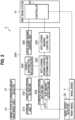
- the electronic controller 200 includes a storage unit 210, a target deceleration setting unit 220, an estimated deceleration setting unit 230, a slip amount detection unit 270, a vehicle information calculation unit 240, an anti-locking braking control determination unit 255, an anti-locking braking control unit 250, and an interlocking braking control unit 260.
- the slip amount detection unit 270 detects a slip amount of the front wheel based on the wheel speed or the like detected by the wheel speed detector 32.
- Deceleration data indicating correspondence relationship between the operation amount to the brake lever L2 on the rear wheel side and a deceleration of a vehicle is stored in the storage unit 210.
- the deceleration data is obtained by actually measuring the deceleration of the vehicle when the brake lever L2 on the rear wheel side is operated in a state in which one person is in the vehicle and no loaded object is on the vehicle.
- the deceleration data according to the present embodiment is three-dimensional map data indicating the operation amount, the deceleration, and a target deceleration on three orthogonal axes, respectively.
- a brake lever angle in FIG. 3 indicates the operation amount to the brake lever L2.
- an increase amount of the target deceleration with respect to an increase amount of a vehicle body speed is set to be larger in a high speed region of the vehicle body speed than in a low speed region of the vehicle body speed.
- the storage unit 210 shown in FIG. 2 stores a slip threshold that is a threshold of a slip amount when it is determined whether the anti-locking braking control is necessary based on the slip amount.
- the storage unit 210 stores a lift threshold that is a threshold of an estimated deceleration when it is determined whether the anti-locking braking control is necessary based on the estimated deceleration.
- a lift threshold that is a threshold of an estimated deceleration when it is determined whether the anti-locking braking control is necessary based on the estimated deceleration.
- a case in which the estimated deceleration is larger than the lift threshold indicates that a load on the front wheel side of a vehicle body increases and a lift state in which the rear wheel side of the vehicle body tends to rise is large.
- the target deceleration setting unit 220 sets the target deceleration, which is a target value of the deceleration of the vehicle, based on the deceleration data from the operation amount to the brake lever L2 detected by the operation amount detector 31.
- the target deceleration is a deceleration obtained when the driver operates the brake lever L2.
- the estimated deceleration setting unit 230 sets the estimated deceleration, which is an estimated value of an actual deceleration of the vehicle, based on the wheel speed detected by the wheel speed detector 32.
- the anti-locking braking control determination unit 255 determines whether the anti-locking braking control is necessary.
- the anti-locking braking control determination unit 255 causes the anti-locking braking control unit 250 to execute the anti-locking braking control when the slip amount is larger than the slip threshold or when the estimated deceleration is larger than the lift threshold.
- the anti-locking braking control determination unit 255 determines that the anti-locking braking control is unnecessary when the slip amount of the wheel is equal to or smaller than the slip threshold and when the estimated deceleration is equal to or smaller than the lift threshold. In this case, the anti-locking braking control determination unit 255 causes the interlocking braking control unit 260 to control the braking force of the wheel brake F on a front side.
- the vehicle information calculation unit 240 compares a magnitude of the target deceleration with a magnitude of the estimated deceleration.
- the interlocking braking control unit 260 adjusts the valve opening pressure of the pressure regulator valve 1 shown in FIG. 1 , opens the inlet valve 2, closes the outlet valve 3, and operates the pump 6. Accordingly, the brake hydraulic pressure acting on the wheel brake F is increased.
- the interlocking braking control unit 260 adjusts the valve opening pressure of the pressure regulator valve 1, drives the motor 20 with a variable value to change a discharge amount of the pump P.
- the interlocking braking control unit 260 adjusts the valve opening pressure of the pressure regulator valve 1 to a first hydraulic pressure, opens the inlet valve 2, closes the outlet valve 3, and operates the pump 6. At this time, the interlocking braking control unit 260 (see FIG. 2 ) maintains the brake hydraulic pressure acting on the wheel brake F by adjusting a discharge amount of the pump 6 to a first set value.
- the interlocking braking control unit 260 adjusts the valve opening pressure of the pressure regulator valve 1 to a second hydraulic pressure smaller than the first hydraulic pressure, opens the inlet valve 2, closes the outlet valve 3, and operates the pump 6. At this time, the interlocking braking control unit 260 (see FIG. 2 ) reduces the brake hydraulic pressure acting on the wheel brake F by adjusting the discharge amount of the pump 6 to a second set value smaller than the first set value.
- the deceleration threshold, the first hydraulic pressure, the second hydraulic pressure, the first set value, and the second set value are stored in the storage unit 210.
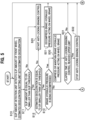
- the slip amount detection unit 270 shown in FIG. 2 detects the slip amount of the front wheel based on the wheel speed of the front wheel, and the estimated deceleration setting unit 230 sets the estimated deceleration (step S10).
- the anti-locking braking control determination unit 255 determines that the front wheel is likely to fall into a locked state. At this time, the anti-locking braking control determination unit 255 causes the anti-locking braking control unit 250 to start the anti-locking braking control (step S20) so as to decompress the brake hydraulic pressure acting on the wheel brake F (step S21).
- the anti-locking braking control determination unit 255 determines that the front wheel is likely to fall into the locked state. At this time, the anti-locking braking control determination unit 255 causes the anti-locking braking control unit 250 to start the anti-locking braking control (step S20) so as to decompress the brake hydraulic pressure acting on the wheel brake F (step S21).
- the anti-locking braking control determination unit 255 determines whether the brake hydraulic pressure is being decompressed by the anti-locking braking control unit 250 (step S13).
- the anti-locking braking control determination unit 255 causes the anti-locking braking control unit 250 to execute control for increasing the brake hydraulic pressure acting on the wheel brake F or holding this brake hydraulic pressure constant (step S30). At this time, the anti-locking braking control determination unit 255 compresses the brake hydraulic pressure acting on the wheel brake F or maintains this brake hydraulic pressure constant based on information from various sensors such as the wheel speed obtained from the wheel speed detector 32.
- step S30 After the anti-locking braking control unit 250 compresses the brake hydraulic pressure acting on the wheel brake F or maintains this brake hydraulic pressure constant (step S30), it is determined whether an elapsed time from the start of the anti-locking braking control reaches an upper limit (step S31).
- step S10 the detection for the slip amount of the front wheel and the setting for the estimated deceleration are repeated (step S10) .
- step S31 When the elapsed time from the start of the anti-locking braking control reaches the upper limit (YES in step S31), the anti-locking braking control unit 250 stops the anti-locking braking control (step S32), and the detection for the slip amount of the front wheel and the setting for the estimated deceleration are repeated (step S10).
- the wheel hydraulic pressure line B is blocked from the master cylinder MC and the wheel hydraulic pressure line B is opened to the release line E on the reservoir 5 side by the control valve means V. Specifically, the inlet valve 2 is brought into the closed state and the outlet valve 3 is brought into the open state by the electronic controller 200.
- the electronic controller 200 determines that the brake hydraulic pressure acting on the wheel brake F is to be held constant, the wheel hydraulic pressure line B and the release line E are blocked by the control valve means V. Specifically, the inlet valve 2 is brought into the closed state and the outlet valve 3 is brought into the closed state by the electronic controller 200.
- the brake fluid is confined in a hydraulic pressure line closed by the wheel brake F, the inlet valve 2, and the outlet valve 3, and as a result, the brake hydraulic pressure acting on the wheel brake F is held constant.
- the wheel hydraulic pressure line B is opened and the release line E is blocked by the control valve means V. Specifically, the inlet valve 2 is brought into the open state and the outlet valve 3 is brought into the closed state by the electronic controller 200.
- the pump 6 is operated as the motor 20 is driven, the brake fluid stored in the reservoir 5 is returned to the wheel hydraulic pressure line B via the discharge line D, and thus the pressure of the brake fluid in the wheel hydraulic pressure line B is increased.
- the anti-locking braking control determination unit 255 shown in FIG. 2 determines that there is no possibility that the front wheel is locked, and thus the anti-locking braking control is not executed.
- a brake hydraulic pressure is generated in the master cylinder MC due to an operation force.
- the brake hydraulic pressure is transmitted to the wheel brake F on the front wheel side via the output hydraulic pressure line A, the pressure regulator valve 1, and the wheel hydraulic pressure line B, and the front wheel is braked.
- the brake lever L1 is released, the brake fluid flowing into the wheel hydraulic pressure line B is returned to the master cylinder MC via the pressure regulator valve 1 and the output hydraulic pressure line A.
- the brake wire W is operated by an operation force, thus the braking force is generated in the wheel brake R on the rear wheel side, and the rear wheel is braked.
- the vehicle information calculation unit 240 acquires the vehicle body speed and the operation amount to the brake lever L2 on the rear wheel side.
- the interlocking braking control unit 260 stops the motor 20 (see FIG. 1 ) of the pump 6 (see FIG. 1 ) (step S41). That is, the interlocking braking control is not executed.
- the target deceleration setting unit 220 sets the target deceleration based on the operation amount to the brake lever L2 on the rear wheel side (step S42). Then, the vehicle information calculation unit 240 compares the magnitude of the target deceleration with the magnitude of the estimated deceleration (step S43).
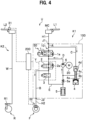
- the interlocking braking control unit 260 closes the pressure regulator valve 1 of the first brake system K1 shown in FIG. 1 , opens the inlet valve 2, closes the outlet valve 3 and operates the motor 20. Accordingly, when the pump 6 is operated, the pressure of the vacuum pressure chamber 4a of the suction valve 4 becomes the vacuum pressure, and the suction valve 4 is brought into the open state, so that the brake fluid in the suction line C is sucked by the pump 6. Then, the brake fluid is discharged from the pump 6 to the discharge line D, the brake fluid flows from the discharge line D into the wheel hydraulic pressure line B, and thus the brake hydraulic pressure in the wheel hydraulic pressure line B is increased (step S45).
- the interlocking braking control unit 260 adjusts the valve opening pressure of the pressure regulator valve 1 and drives, based on the difference between the target deceleration and the estimated deceleration, the motor 20 with the variable value to change the discharge amount of the pump P, and thus the brake hydraulic pressure acting on the wheel brake F on the front wheel side is adjusted according to a use condition and a specification of the vehicle.
- the interlocking braking control unit 260 determines whether the difference between the target deceleration and the estimated deceleration is equal to or smaller than the deceleration threshold (step S46).
- the interlocking braking control unit 260 adjusts the valve opening pressure of the pressure regulator valve 1 to the first hydraulic pressure, opens the inlet valve 2, closes the outlet valve 3, and operates the motor 20.
- the interlocking braking control unit 260 drives the motor 20 with a fixed value to adjust the discharge amount of the pump 6 to the first set value. In this way, the brake hydraulic pressure acting on the wheel brake F is held so as to maintain the difference between the target deceleration and the estimated deceleration (step S47).
- the interlocking braking control unit 260 adjusts the brake hydraulic pressure in the pressure regulator valve 1 to the second hydraulic pressure smaller than the first hydraulic pressure, opens the inlet valve 2, closes the outlet valve 3, and operates the motor 20. At this time, the interlocking braking control unit 260 (see FIG. 2 ) drives the motor 20 with the fixed value to adjust the discharge amount of the pump 6 to the second set value smaller than the first set value. In this way, the brake hydraulic pressure acting on the wheel brake F is decompressed according to the use condition and the specification of the vehicle (step S48).
- the braking force of the wheel brake F is controlled by referring to the wheel speed in addition to the operation amount to the brake lever L2 on the rear wheel side. Therefore, even when a weight of a loaded object loaded on the vehicle varies, the vehicle can be braked in the same manner as long as the operation amount is the same.
- the vehicle is braked according to the operation amount to the brake lever L2 while being less likely to be affected by the weight of the loaded object, and therefore, operation feel for the driver can be improved.
- the brake device U according to the present embodiment can be applied to a brake system including a mechanical second brake system K2.
- the braking force of the wheel can be controlled even without using a hydraulic pressure sensor for braking control. Since the number of components in the controller 50 (modulator) is reduced if the hydraulic pressure sensor is omitted, a manufacturing cost can be reduced, and a size and a weight can be reduced.
- control executed by the electronic controller 200 can be simplified, and versatility can be enhanced.
- the anti-locking braking control for preventing locking of the wheel can be executed, and the braking force of the wheel brake F is controlled by referring to the wheel speed in addition to the operation amount to the brake lever L1, the operation feel for the driver can be improved. Further, in the brake device U according to the present embodiment, the anti-locking braking control can be executed while preventing slip of the wheel and lift of the vehicle body.
- the suction valve 4 of the brake device U is a mechanical valve that is opened and closed by a pressure difference, and opening and closing of the suction valve 4 is automated, and therefore, the control executed by the electronic controller 200 can be simplified, and the manufacturing cost can be reduced.
- the operation amount to the brake lever L2 is detected based on the tilt angle of the brake lever L2 on the rear wheel side, but the operation amount to the brake lever L2 may be detected based on an operation of another part in the second brake system K2.
- the operation amount to the brake lever L2 can also be detected based on a tilt angle of the rod R1 of the wheel brake R on the rear wheel side.
- the electronic controller 200 can execute the anti-locking braking non-control, the anti-locking braking control, and the interlocking braking control, but the electronic controller 200 may be configured to execute other braking control.
- the electronic controller 200 may be configured to execute braking assist control for generating the braking force in the wheel brake F on the front wheel side by operating the pump 6 in a state in which the pressure regulator valve 1 is opened and causing the brake fluid to flow into the wheel hydraulic pressure line B when the brake lever L1 on the front wheel side is operated.
- the second brake system K2 is a mechanical brake system, but the second brake system may be a hydraulic brake system.
- the brake device according to the invention can also be applied to a four-wheeled bar handle vehicle as long as the brake device according to the invention includes an independent brake system.
- wheel brakes of two front wheels are connected to one brake system
- wheel brakes of two rear wheels are connected to the other brake system.
- the brake lever L2 on the rear wheel side may be used as a brake pedal.
- the mechanical suction valve 4 is used, but the suction valve may be implemented by a solenoid valve that is opened and closed based on a command from the electronic controller 200.
Landscapes
- Engineering & Computer Science (AREA)
- Mechanical Engineering (AREA)
- Transportation (AREA)
- Physics & Mathematics (AREA)
- Fluid Mechanics (AREA)
- Regulating Braking Force (AREA)
- Braking Systems And Boosters (AREA)
Abstract
Description
- The present invention relates to a brake device for a vehicle.
- As a brake device mainly used in a bar handle type vehicle such as a motorcycle, a motor tricycle, and an all-terrain vehicle (ATV), there is a brake device that controls a braking force of a wheel brake based on a brake hydraulic pressure of a hydraulic brake system (for example, see Patent Literature 1).
- Patent Literature 1:
WO 2018/078475 - The brake device for a vehicle in the related art described above has a problem that, even when an operation amount that a driver applies to a brake lever is the same, braking of the vehicle differs between a case in which a weight of a loaded object loaded on the vehicle is large and a case in which a weight of a loaded object loaded on the vehicle is small.
- The brake device for a vehicle in the related art further has a problem that the number of components in a modulator is large and control is complicated since a braking force of a wheel brake is controlled based on brake hydraulic pressures detected by a plurality of hydraulic pressure sensors.
- An object of the invention is to provide a brake device for a vehicle, which can solve the problems described above, improve operation feel for the driver, reduce the number of the components in the modulator, and simplify the control.
- In order to solve the above problems, the invention provides a brake device for a vehicle including: an operation amount detector configured to detect an operation amount to an operator; a wheel speed detector configured to detect a wheel speed; a controller configured to control a braking force of a wheel brake; and an electronic controller. The electronic controller includes: a target deceleration setting unit configured to set a target deceleration, which is a target value of a deceleration of the vehicle, based on the operation amount to the operator; and an estimated deceleration setting unit configured to set an estimated deceleration, which is an estimated value of the deceleration of the vehicle, based on the wheel speed detected by the wheel speed detector. Further, the electronic controller includes a braking control unit configured to control the controller based on the target deceleration and the estimated deceleration.
- In the brake device for a vehicle according to the invention, since the braking force of the wheel brake is controlled by referring to the wheel speed in addition to the operation amount to the operator, even when a weight of a loaded object loaded on the vehicle varies, the vehicle can be braked in the same manner as long as the operation amount is the same. Accordingly, in the brake device for a vehicle according to the invention, since the vehicle is braked according to the operation amount to the operator while being less likely to be affected by the weight of the loaded object, operation feel for a driver can be improved.
- The brake device for a vehicle according to the invention controls the braking force of the wheel brake based on the operation amount to the operator and the wheel speed, and thus can also be applied to a brake system other than a hydraulic brake system.
- In the brake device for a vehicle according to the invention, a braking force of a wheel can be controlled even without using a hydraulic pressure sensor for braking control. Further, since the number of components in a modulator is reduced if the hydraulic pressure sensor is omitted, a manufacturing cost can be reduced, and a size and a weight can be reduced.
- In the brake device for a vehicle according to the invention, since the target deceleration is set based on the wheel speed, the control can be simplified and versatility can be enhanced.
- It is preferable that in the brake device for a vehicle, deceleration data indicating correspondence relationship between the operation amount to the operator and the deceleration of the vehicle is stored in the electronic controller, and the target deceleration setting unit accurately sets the target deceleration based on the deceleration data.
- It is preferable that in the brake device for a vehicle, the braking control unit executes braking control matching the target deceleration by executing braking control for controlling a brake hydraulic pressure acting on the wheel brake based on a difference between the target deceleration and the estimated deceleration.
- In the brake device for a vehicle, the electronic controller includes: an anti-locking braking control unit configured to execute anti-locking braking control for preventing locking of a wheel by increasing, decreasing, or holding a brake hydraulic pressure of the wheel brake by the controller; and an anti-locking braking control determination unit configured to determine whether the anti-locking braking control is necessary. When the anti-locking braking control determination unit determines that the anti-locking braking control is necessary, the anti-locking braking control unit executes the anti-locking braking control. When the anti-locking braking control determination unit determines that the anti-locking braking control is unnecessary, the braking control unit controls the braking force of the wheel brake.
- In the configuration, since the anti-locking braking control can be executed, and the braking force of the wheel brake is controlled based on the operation amount to the operator and the wheel speed, the operation feel for the driver can be improved.
- In the brake device for a vehicle, the electronic controller includes a slip amount detection unit configured to detect a slip amount of the wheel. In the anti-locking braking control determination unit, when the slip amount is larger than a slip threshold or when the estimated deceleration is larger than a lift threshold, the anti-locking braking control is executed.
- In the configuration, the anti-locking braking control can be executed while preventing slip of the wheel and lift of a vehicle body.
- The brake device for a vehicle may include: two operators which are respectively on a front wheel side and a rear wheel side; two wheel brakes which are respectively on the front wheel side and the rear wheel side; a first brake system in which one of the operators and one of the wheel brakes are connected; and a second brake system in which the other of the operators and the other of the wheel brakes are connected. In this case, the target deceleration setting unit sets the target deceleration based on an operation amount to the other operator, and the braking control unit controls the controller provided in the first brake system based on the target deceleration and the estimated deceleration.
- In the configuration, braking control of the first brake system can be executed by operating the one operator, and further, the braking control of the first brake system can be executed when the other operator is operated.
- In the brake device for a vehicle, the first brake system may include: a hydraulic pressure line in which a brake hydraulic pressure is generated by the one operator or a pump; and control valve means provided in the hydraulic pressure line. In this case, the control unit can control a braking force of the one wheel brake by switching opening and closing of the control valve means in conjunction with a braking force of the other wheel brake.
- In the brake device for a vehicle, the braking control unit can generate a braking force in the one wheel brake by operating the pump based on an operation amount to the other operator.
- In the configuration, the braking force can be generated in the wheel brake of the first brake system in conjunction with the wheel brake of a hydraulic, mechanical, or electric second brake system.
- It is preferable that in the brake device for a vehicle, the braking control unit executes interlocking braking control matching the target deceleration by increasing, decreasing, or holding the brake hydraulic pressure of the one wheel brake by switching the opening and closing of the control valve means.
- In the brake device for a vehicle, the control valve means includes: a pressure regulator valve; an inlet valve leading to the pressure regulator valve and to the one wheel brake; and an outlet valve leading to the one wheel brake and to a suction side of the pump. The brake hydraulic pressure acting on the one wheel brake from the one operator is capable of being adjusted by adjusting a valve opening pressure of the pressure regulator valve. When the estimated deceleration is equal to or smaller than the target deceleration, the braking control unit adjusts the valve opening pressure of the pressure regulator valve, opens the inlet valve, closes the outlet valve, and operates the pump. At this time, it is preferable to increase the braking force of the wheel brake, by changing a discharge amount of the pump based on the difference between the target deceleration and the estimated deceleration to increase the brake hydraulic pressure.
- In the brake device for a vehicle, when the estimated deceleration is larger than the target deceleration and the difference between the target deceleration and the estimated deceleration is equal to or smaller than a compression/decompression threshold, the braking control unit adjusts the valve opening pressure of the pressure regulator valve to a first hydraulic pressure, opens the inlet valve, closes the outlet valve, operates the pump, and adjusts the discharge amount of the pump to a first set value.
- In the configuration, the brake hydraulic pressure is increased by adjusting the discharge amount of the pump to a set value, and thus the braking force of the wheel brake can be held or increased according to a use condition or a specification of the vehicle.
- In the brake device for a vehicle, when the estimated deceleration is larger than the target deceleration and the difference between the target deceleration and the estimated deceleration is larger than the compression/decompression threshold, the braking control unit adjusts the valve opening pressure of the pressure regulator valve to a second hydraulic pressure smaller than the first hydraulic pressure, opens the inlet valve, and closes the outlet valve, operates the pump, and adjusts the discharge amount of the pump to a second set value smaller than the first set value.
- In the configuration, the brake hydraulic pressure is reduced by reducing the discharge amount of the pump, and thus the braking force of the wheel brake can be reduced according to the use condition and the specification of the vehicle.
- In the brake device for a vehicle according to the invention, since braking control corresponding to the difference between the target deceleration and the estimated deceleration can be executed, the braking control is less likely to be affected by a weight of a loaded object, and operation feel for a driver can be improved. The brake device for a vehicle according to the invention can be applied to various brake systems, and can simplify control. The brake device for a vehicle according to the invention can reduce the number of components.
-
- [
FIG. 1] FIG. 1 is a configuration diagram of a brake device according to an embodiment of the invention. - [
FIG. 2] FIG. 2 is a configuration diagram of an electronic controller according to the embodiment of the invention. - [
FIG. 3] FIG. 3 is a diagram showing deceleration data according to the embodiment of the invention. - [
FIG. 4] FIG. 4 is a configuration diagram of the brake device during interlocking braking control according to the embodiment of the invention. - [
FIG. 5] FIG. 5 is a flowchart showing braking control in the brake device according to the embodiment of the present invention. - [
FIG. 6] FIG. 6 is a flowchart showing the braking control in the brake device according to the embodiment of the present invention. - An embodiment of the invention will be described in detail with reference to the drawings as appropriate.
- As shown in
FIG. 1 , a brake device U for a vehicle (hereinafter, simply referred to as a "brake device") according to the present embodiment is used in a bar handle type vehicle such as a motorcycle, a motor tricycle, and an all-terrain vehicle (ATV). - The brake device U includes two brake levers L1 and L2 on a front wheel side and a rear wheel side, two wheel brakes F and R on the front wheel side and the rear wheel side, a first brake system K1, a second brake system K2, a
metal base 100, and amotor 20. Further, the brake device U includes anoperation amount detector 31 that detects an operation amount to the brake lever L2, awheel speed detector 32 that detects a wheel speed, acontroller 50, and anelectronic controller 200. Thewheel speed detector 32 is a wheel speed sensor that detects a wheel speed of a front wheel. - The brake device U can execute anti-locking braking control for the wheel brake F on the front wheel side. Further, the brake device U can execute interlocking braking control for generating a braking force in the wheel brake F on the front wheel side in conjunction with the wheel brake R on the rear wheel side.
- The first brake system K1 is a hydraulic circuit for applying a brake hydraulic pressure to the wheel brake F on the front wheel side. The wheel brake F on the front wheel side is a hydraulic disc brake that generates a braking force on a wheel by sandwiching a disk between pads by a brake hydraulic pressure acting on a wheel cylinder.
- The first brake system K1 is provided between a master cylinder MC and the wheel brake F. The first brake system K1 is a system extending from an inlet port J1 to an outlet port J2 of the
base 100. A pipe H1 extending to the master cylinder MC is connected to the inlet port J1, and a pipe H2 extending to the wheel brake F is connected to the outlet port J2. - The brake lever L1, which is an operator, is connected to the master cylinder MC. The master cylinder MC generates a brake hydraulic pressure corresponding to a force applied to the brake lever L1 by a driver. The master cylinder MC is connected to the wheel brake F via the first brake system K1.
- The first brake system K1 includes a
hydraulic pressure line 10 extending from the master cylinder MC to the wheel brake F, and thecontroller 50. Thecontroller 50 is a modulator that controls the braking force of the wheel brake F. Thecontroller 50 includes a pressure regulator valve 1, control valve means V, asuction valve 4, areservoir 5, and apump 6, and these components are assembled to thebase 100. - In the following description, in the
hydraulic pressure line 10, a hydraulic pressure line extending from the inlet port J1 to the pressure regulator valve 1 is referred to as an "output hydraulic pressure line A", and a hydraulic pressure line extending from the pressure regulator valve 1 to the wheel brake F is referred to as a "wheel hydraulic pressure line B". In thehydraulic pressure line 10, a hydraulic pressure line branching from the output hydraulic pressure line A and extending to thepump 6 is referred to as a "suction line C", and a hydraulic pressure line extending from thepump 6 to the wheel hydraulic pressure line B is referred to as a "discharge line D". Further, in thehydraulic pressure line 10, a hydraulic pressure line extending from the wheel hydraulic pressure line B to the suction line C is referred to as a "release line E". An "upstream side" means a master cylinder MC side, and a "downstream side" means a wheel brake F side. - The pressure regulator valve 1 is a normally open proportional solenoid valve (linear solenoid valve) interposed between the output hydraulic pressure line A and the wheel hydraulic pressure line B. An electromagnetic coil of the pressure regulator valve 1, which drives a valve body of the pressure regulator valve 1, is electrically connected to the
electronic controller 200. - Based on a command from the
electronic controller 200, the pressure regulator valve 1 is brought into a closed state when the electromagnetic coil is excited, and is brought into an open state when the electromagnetic coil is demagnetized. - The pressure regulator valve 1 is brought into the open state when a differential pressure between the brake hydraulic pressure on a wheel hydraulic pressure line B side (wheel brake F side) and the brake hydraulic pressure on an output hydraulic pressure line A side (master cylinder MC side) in the closed state is larger than or equal to a valve opening pressure. Accordingly, a brake fluid flows from the wheel hydraulic pressure line B side to the output hydraulic pressure line A side through the pressure regulator valve 1.
- In the pressure regulator valve 1, the valve opening pressure can be adjusted by adjusting a value of a current flowing through the electromagnetic coil based on the command from the
electronic controller 200. - The brake hydraulic pressure in the wheel hydraulic pressure line B is adjusted to a predetermined pressure when the brake fluid flows from the wheel hydraulic pressure line B to the output hydraulic pressure line A through the pressure regulator valve 1. That is, the brake hydraulic pressure acting on the wheel brake F can be adjusted by adjusting the valve opening pressure of the pressure regulator valve 1.
- The pressure regulator valve 1 includes a
check valve 1a. Thecheck valve 1a is connected in parallel to the pressure regulator valve 1. Thecheck valve 1a is a one-way valve that allows the brake fluid to flow from the output hydraulic pressure line A to the wheel hydraulic pressure line B. - The control valve means V has a function of switching among a state in which the wheel hydraulic pressure line B is opened while the release line E is blocked, a state in which the wheel hydraulic pressure line B is blocked while the release line E is opened, and a state in which the wheel hydraulic pressure line B and the release line E are blocked. The control valve means V includes an
inlet valve 2, acheck valve 2a, and anoutlet valve 3. - The
inlet valve 2 is a normally open solenoid valve provided in the wheel hydraulic pressure line B, and leads to the pressure regulator valve 1 and the wheel brake F.The inlet valve 2 allows the brake fluid to flow from the upstream side to the downstream side in an open state, and blocks the flow of the brake fluid between the upstream side and the downstream side in a closed state. - An electromagnetic coil of the
inlet valve 2, which drives a valve body of theinlet valve 2, is electrically connected to theelectronic controller 200, and based on a command from theelectronic controller 200, theinlet valve 2 is brought into the closed state when the electromagnetic coil is excited, and is brought into the open state when the electromagnetic coil is demagnetized. - The
check valve 2a is a one-way valve that allows only flow of the brake fluid from the downstream side to the upstream side, and is connected in parallel to theinlet valve 2. - The
outlet valve 3 is a normally closed solenoid valve provided in the release line E, and leads to the wheel brake F and a suction side of a pump P to be described later. Theoutlet valve 3 blocks flow of the brake fluid between the wheel brake F side and areservoir 5 side in a closed state, and allows the brake fluid to flow from the wheel brake F side to thereservoir 5 side in an open state. - An electromagnetic coil of the
outlet valve 3, which drives a valve body of theoutlet valve 3, is electrically connected to theelectronic controller 200, and based on a command from theelectronic controller 200, theoutlet valve 3 is brought into the open state when the electromagnetic coil is excited, and is brought into the closed state when the electromagnetic coil is demagnetized. - The
reservoir 5 is provided in the release line E, and has a function of temporarily storing the brake fluid released by opening theoutlet valve 3. Acheck valve 5a, which allows only flow of the brake fluid from thereservoir 5 side to apump 6 side, is interposed between thereservoir 5 and thepump 6. - The
pump 6 is interposed between the suction line C and the discharge line D. Thepump 6 is driven by a rotational force of themotor 20, sucks the brake fluid stored in thereservoir 5 of the suction line C, and discharges the brake fluid to the discharge line D. - The
motor 20 is a power source of thepump 6 provided in the first brake system K1, and is an electric component that operates based on a command from theelectronic controller 200. - The
suction valve 4 switches between a state in which the suction line C is opened and a state in which the suction line C is blocked. Thesuction valve 4 is normally closed, and is opened by a difference between the brake hydraulic pressure on the output hydraulic pressure line A side (master cylinder MC side) and a brake hydraulic pressure on a suction port side of thepump 6. - When the
pump 6 operates and a pressure of the suction line C on the suction port side of thepump 6 becomes a vacuum pressure, as shown inFIG. 4 , a pressure of avacuum pressure chamber 4a communicating with the suction line C on the suction port side of thepump 6 becomes a vacuum pressure. Adiaphragm 4b of thesuction valve 4 is elastically deformed toward avalve body 4d side by this vacuum pressure, and a plunger 4c pushes up avalve body 4d. Accordingly, thevalve body 4d is separated from a valve seat, and thesuction valve 4 is brought into an open state. - The second brake system K2 directly operates the wheel brake R on the rear wheel side by an operation to the brake lever L2, which is a brake operator, to generate a braking force.
- One end of a brake wire W is connected to the brake lever L2. The other end of the brake wire W is connected to a rod R1 of the wheel brake R on the rear wheel side.
- The wheel brake R on the rear wheel side is a mechanical drum brake that generates a braking force on the wheel when the brake wire W is pulled by the operation on the brake lever L2 to tilt the rod R1 and press a brake shoe against an inner peripheral surface of a drum.
- The second brake system K2 is provided with the
operation amount detector 31 that detects the operation amount to the brake lever L2 on the rear wheel side. - The
operation amount detector 31 is an angle sensor that detects a tilt angle of the brake lever L2 when the driver operates the brake lever L2. The tilt angle of the brake lever L2 measured by theoperation amount detector 31 is taken into theelectronic controller 200 as needed. - The
electronic controller 200 is a microcomputer including a central processing unit (CPU), a read only memory (ROM), a random access memory (RAM), and the like. Theelectronic controller 200 according to the present embodiment executes the anti-locking braking control and the interlocking braking control. - The
electronic controller 200 controls opening and closing of the pressure regulator valve 1, theinlet valve 2, and theoutlet valve 3 and controls an operation of themotor 20 based on various information from theoperation amount detector 31, thewheel speed detector 32, and the like. - As shown in
FIG. 2 , theelectronic controller 200 includes astorage unit 210, a targetdeceleration setting unit 220, an estimateddeceleration setting unit 230, a slipamount detection unit 270, a vehicleinformation calculation unit 240, an anti-locking brakingcontrol determination unit 255, an anti-lockingbraking control unit 250, and an interlockingbraking control unit 260. - The slip
amount detection unit 270 detects a slip amount of the front wheel based on the wheel speed or the like detected by thewheel speed detector 32. - Deceleration data indicating correspondence relationship between the operation amount to the brake lever L2 on the rear wheel side and a deceleration of a vehicle is stored in the
storage unit 210. The deceleration data is obtained by actually measuring the deceleration of the vehicle when the brake lever L2 on the rear wheel side is operated in a state in which one person is in the vehicle and no loaded object is on the vehicle. - As shown in
FIG. 3 , the deceleration data according to the present embodiment is three-dimensional map data indicating the operation amount, the deceleration, and a target deceleration on three orthogonal axes, respectively. A brake lever angle inFIG. 3 indicates the operation amount to the brake lever L2. - In the present embodiment, an increase amount of the target deceleration with respect to an increase amount of a vehicle body speed is set to be larger in a high speed region of the vehicle body speed than in a low speed region of the vehicle body speed.
- The
storage unit 210 shown inFIG. 2 stores a slip threshold that is a threshold of a slip amount when it is determined whether the anti-locking braking control is necessary based on the slip amount. - Further, the
storage unit 210 stores a lift threshold that is a threshold of an estimated deceleration when it is determined whether the anti-locking braking control is necessary based on the estimated deceleration. A case in which the estimated deceleration is larger than the lift threshold indicates that a load on the front wheel side of a vehicle body increases and a lift state in which the rear wheel side of the vehicle body tends to rise is large. - The target
deceleration setting unit 220 sets the target deceleration, which is a target value of the deceleration of the vehicle, based on the deceleration data from the operation amount to the brake lever L2 detected by theoperation amount detector 31. The target deceleration is a deceleration obtained when the driver operates the brake lever L2. - The estimated
deceleration setting unit 230 sets the estimated deceleration, which is an estimated value of an actual deceleration of the vehicle, based on the wheel speed detected by thewheel speed detector 32. - The anti-locking braking
control determination unit 255 determines whether the anti-locking braking control is necessary. The anti-locking brakingcontrol determination unit 255 causes the anti-lockingbraking control unit 250 to execute the anti-locking braking control when the slip amount is larger than the slip threshold or when the estimated deceleration is larger than the lift threshold. - The anti-locking braking
control determination unit 255 determines that the anti-locking braking control is unnecessary when the slip amount of the wheel is equal to or smaller than the slip threshold and when the estimated deceleration is equal to or smaller than the lift threshold. In this case, the anti-locking brakingcontrol determination unit 255 causes the interlockingbraking control unit 260 to control the braking force of the wheel brake F on a front side. - The vehicle
information calculation unit 240 compares a magnitude of the target deceleration with a magnitude of the estimated deceleration. - When the estimated deceleration is equal to or smaller than the target deceleration, the interlocking
braking control unit 260 adjusts the valve opening pressure of the pressure regulator valve 1 shown inFIG. 1 , opens theinlet valve 2, closes theoutlet valve 3, and operates thepump 6. Accordingly, the brake hydraulic pressure acting on the wheel brake F is increased. At this time, in order to make the estimated deceleration approach the target deceleration, based on a difference between the target deceleration and the estimated deceleration, the interlockingbraking control unit 260 adjusts the valve opening pressure of the pressure regulator valve 1, drives themotor 20 with a variable value to change a discharge amount of the pump P. - When the estimated deceleration is larger than the target deceleration and the difference between the target deceleration and the estimated deceleration is equal to or smaller than a deceleration threshold, the interlocking braking control unit 260 (see
FIG. 2 ) adjusts the valve opening pressure of the pressure regulator valve 1 to a first hydraulic pressure, opens theinlet valve 2, closes theoutlet valve 3, and operates thepump 6. At this time, the interlocking braking control unit 260 (seeFIG. 2 ) maintains the brake hydraulic pressure acting on the wheel brake F by adjusting a discharge amount of thepump 6 to a first set value. - When the estimated deceleration is larger than the target deceleration and the difference between the target deceleration and the estimated deceleration is larger than a previous speed threshold, the interlocking braking control unit 260 (see
FIG. 2 ) adjusts the valve opening pressure of the pressure regulator valve 1 to a second hydraulic pressure smaller than the first hydraulic pressure, opens theinlet valve 2, closes theoutlet valve 3, and operates thepump 6. At this time, the interlocking braking control unit 260 (seeFIG. 2 ) reduces the brake hydraulic pressure acting on the wheel brake F by adjusting the discharge amount of thepump 6 to a second set value smaller than the first set value. - The deceleration threshold, the first hydraulic pressure, the second hydraulic pressure, the first set value, and the second set value are stored in the
storage unit 210. - Next, the anti-locking braking control, anti-locking braking non-control, and the interlocking braking control implemented by the brake device U according to the present embodiment will be described. In the following description, flowcharts in
FIGS. 5 and6 will be referred to as appropriate. - First, when the driver operates the brake lever L1 shown in
FIG. 1 on the front wheel side, the slipamount detection unit 270 shown inFIG. 2 detects the slip amount of the front wheel based on the wheel speed of the front wheel, and the estimateddeceleration setting unit 230 sets the estimated deceleration (step S10). - When the slip amount is larger than the slip threshold (NO in step S11), the anti-locking braking
control determination unit 255 determines that the front wheel is likely to fall into a locked state. At this time, the anti-locking brakingcontrol determination unit 255 causes the anti-lockingbraking control unit 250 to start the anti-locking braking control (step S20) so as to decompress the brake hydraulic pressure acting on the wheel brake F (step S21). - When the slip amount is equal to or smaller than the slip threshold (YES in step S11) and the estimated deceleration is larger than the lift threshold (NO in step S12), the anti-locking braking
control determination unit 255 determines that the front wheel is likely to fall into the locked state. At this time, the anti-locking brakingcontrol determination unit 255 causes the anti-lockingbraking control unit 250 to start the anti-locking braking control (step S20) so as to decompress the brake hydraulic pressure acting on the wheel brake F (step S21). - When the slip amount is equal to or smaller than the slip threshold (YES in step S11) and the estimated deceleration is equal to or smaller than the lift threshold (YES in step S12), the anti-locking braking
control determination unit 255 determines whether the brake hydraulic pressure is being decompressed by the anti-locking braking control unit 250 (step S13). - When the brake hydraulic pressure is being decompressed by the anti-locking braking control unit 250 (YES in step S13), the anti-locking braking
control determination unit 255 causes the anti-lockingbraking control unit 250 to execute control for increasing the brake hydraulic pressure acting on the wheel brake F or holding this brake hydraulic pressure constant (step S30). At this time, the anti-locking brakingcontrol determination unit 255 compresses the brake hydraulic pressure acting on the wheel brake F or maintains this brake hydraulic pressure constant based on information from various sensors such as the wheel speed obtained from thewheel speed detector 32. - After the anti-locking
braking control unit 250 compresses the brake hydraulic pressure acting on the wheel brake F or maintains this brake hydraulic pressure constant (step S30), it is determined whether an elapsed time from the start of the anti-locking braking control reaches an upper limit (step S31). - Then, when the elapsed time does not reach the upper limit (NO in step S31), the detection for the slip amount of the front wheel and the setting for the estimated deceleration are repeated (step S10) .
- When the elapsed time from the start of the anti-locking braking control reaches the upper limit (YES in step S31), the anti-locking
braking control unit 250 stops the anti-locking braking control (step S32), and the detection for the slip amount of the front wheel and the setting for the estimated deceleration are repeated (step S10). - When the
electronic controller 200 shown inFIG. 1 determines that the brake hydraulic pressure acting on the wheel brake F is to be decompressed, the wheel hydraulic pressure line B is blocked from the master cylinder MC and the wheel hydraulic pressure line B is opened to the release line E on thereservoir 5 side by the control valve means V. Specifically, theinlet valve 2 is brought into the closed state and theoutlet valve 3 is brought into the open state by theelectronic controller 200. - In this way, the brake fluid in the wheel hydraulic pressure line B leading to the wheel brake F flows into the
reservoir 5 through the release line E, and as a result, the brake hydraulic pressure acting on the wheel brake F is decompressed. - When the
electronic controller 200 determines that the brake hydraulic pressure acting on the wheel brake F is to be held constant, the wheel hydraulic pressure line B and the release line E are blocked by the control valve means V. Specifically, theinlet valve 2 is brought into the closed state and theoutlet valve 3 is brought into the closed state by theelectronic controller 200. - In this way, the brake fluid is confined in a hydraulic pressure line closed by the wheel brake F, the
inlet valve 2, and theoutlet valve 3, and as a result, the brake hydraulic pressure acting on the wheel brake F is held constant. - When the
electronic controller 200 determines that the brake hydraulic pressure acting on the wheel brake F is to be compressed, the wheel hydraulic pressure line B is opened and the release line E is blocked by the control valve means V. Specifically, theinlet valve 2 is brought into the open state and theoutlet valve 3 is brought into the closed state by theelectronic controller 200. When themotor 20 is driven by theelectronic controller 200, thepump 6 is operated as themotor 20 is driven, the brake fluid stored in thereservoir 5 is returned to the wheel hydraulic pressure line B via the discharge line D, and thus the pressure of the brake fluid in the wheel hydraulic pressure line B is increased. - At this time, since a spring provided in the
reservoir 5 biases a piston of thereservoir 5 to cause the piston to return to an initial position, pressures in the release line E and the suction line C are increased. At this time, thesuction valve 4 is in a closed state until pressure boosting from thereservoir 5 ends (thereservoir 5 runs out of the brake fluid). - When pressure boosting control is continuously executed after the
reservoir 5 runs out of the brake fluid, as shown inFIG. 4 , thepump 6 is continuously operated, the pressure of thevacuum pressure chamber 4a of thesuction valve 4 becomes the vacuum pressure, thus thevalve body 4d is pushed up by the plunger 4c, and thesuction valve 4 is brought into the open state. - When the
suction valve 4 is brought into the open state, the brake fluid flowing into thevacuum pressure chamber 4a from the suction line C on the master cylinder MC side flows into the suction line C on thepump 6 side and is sucked by thepump 6. - When the slip amount is equal to or smaller than the slip threshold (YES in step S11) and then the estimated deceleration is equal to or smaller than the lift threshold (YES in step S12), the anti-locking braking
control determination unit 255 shown inFIG. 2 determines that there is no possibility that the front wheel is locked, and thus the anti-locking braking control is not executed. - During the anti-locking braking non-control, as shown in
FIG. 1 , in the first brake system K1, all of the plurality of electromagnetic coils that drive the plurality of solenoid valves are demagnetized by theelectronic controller 200. That is, in normal braking control, the pressure regulator valve 1 and theinlet valve 2 are in the open state, and theoutlet valve 3 and thesuction valve 4 are in the closed state. - When the driver operates the brake lever L1 on the front wheel side during the anti-locking braking non-control, a brake hydraulic pressure is generated in the master cylinder MC due to an operation force. The brake hydraulic pressure is transmitted to the wheel brake F on the front wheel side via the output hydraulic pressure line A, the pressure regulator valve 1, and the wheel hydraulic pressure line B, and the front wheel is braked. When the brake lever L1 is released, the brake fluid flowing into the wheel hydraulic pressure line B is returned to the master cylinder MC via the pressure regulator valve 1 and the output hydraulic pressure line A.
- In the second brake system K2, when the driver operates the brake lever L2 on the rear wheel side, the brake wire W is operated by an operation force, thus the braking force is generated in the wheel brake R on the rear wheel side, and the rear wheel is braked.
- In a state in which the anti-locking
braking control unit 250 shown inFIG. 2 does not execute the anti-locking braking control (NO in step S13), when the driver operates the brake lever L2 on the rear wheel side or operates both the front and rear brake levers L1 and L2, the vehicleinformation calculation unit 240 acquires the vehicle body speed and the operation amount to the brake lever L2 on the rear wheel side. - When the vehicle body speed is equal to or smaller than a predetermined threshold and the operation amount to the brake lever L2 is equal to or smaller than a predetermined threshold (NO in step S40), the interlocking
braking control unit 260 stops the motor 20 (seeFIG. 1 ) of the pump 6 (seeFIG. 1 ) (step S41). That is, the interlocking braking control is not executed. - When the vehicle body speed is larger than the predetermined threshold and the operation amount to the brake lever L2 is larger than the predetermined threshold (YES in step S40), the target
deceleration setting unit 220 sets the target deceleration based on the operation amount to the brake lever L2 on the rear wheel side (step S42). Then, the vehicleinformation calculation unit 240 compares the magnitude of the target deceleration with the magnitude of the estimated deceleration (step S43). - When the estimated deceleration is equal to or smaller than the target deceleration (YES in step S44), the interlocking
braking control unit 260 closes the pressure regulator valve 1 of the first brake system K1 shown inFIG. 1 , opens theinlet valve 2, closes theoutlet valve 3 and operates themotor 20. Accordingly, when thepump 6 is operated, the pressure of thevacuum pressure chamber 4a of thesuction valve 4 becomes the vacuum pressure, and thesuction valve 4 is brought into the open state, so that the brake fluid in the suction line C is sucked by thepump 6. Then, the brake fluid is discharged from thepump 6 to the discharge line D, the brake fluid flows from the discharge line D into the wheel hydraulic pressure line B, and thus the brake hydraulic pressure in the wheel hydraulic pressure line B is increased (step S45). - At this time, in order to make the estimated deceleration approach the target deceleration, the interlocking
braking control unit 260 adjusts the valve opening pressure of the pressure regulator valve 1 and drives, based on the difference between the target deceleration and the estimated deceleration, themotor 20 with the variable value to change the discharge amount of the pump P, and thus the brake hydraulic pressure acting on the wheel brake F on the front wheel side is adjusted according to a use condition and a specification of the vehicle. - When the estimated deceleration is larger than the target deceleration (NO in step S44), the interlocking
braking control unit 260 determines whether the difference between the target deceleration and the estimated deceleration is equal to or smaller than the deceleration threshold (step S46). - Then, when the difference between the target deceleration and the estimated deceleration is equal to or smaller than the deceleration threshold (YES in step S46), the interlocking braking control unit 260 (see
FIG. 2 ) adjusts the valve opening pressure of the pressure regulator valve 1 to the first hydraulic pressure, opens theinlet valve 2, closes theoutlet valve 3, and operates themotor 20. At this time, the interlocking braking control unit 260 (seeFIG. 2 ) drives themotor 20 with a fixed value to adjust the discharge amount of thepump 6 to the first set value. In this way, the brake hydraulic pressure acting on the wheel brake F is held so as to maintain the difference between the target deceleration and the estimated deceleration (step S47). - When the estimated deceleration is larger than the target deceleration (NO in step S44) and the difference between the target deceleration and the estimated deceleration is larger than the deceleration threshold (NO in step S46), the interlocking braking control unit 260 (see
FIG. 2 ) adjusts the brake hydraulic pressure in the pressure regulator valve 1 to the second hydraulic pressure smaller than the first hydraulic pressure, opens theinlet valve 2, closes theoutlet valve 3, and operates themotor 20. At this time, the interlocking braking control unit 260 (seeFIG. 2 ) drives themotor 20 with the fixed value to adjust the discharge amount of thepump 6 to the second set value smaller than the first set value. In this way, the brake hydraulic pressure acting on the wheel brake F is decompressed according to the use condition and the specification of the vehicle (step S48). - In the brake device U as described above, the braking force of the wheel brake F is controlled by referring to the wheel speed in addition to the operation amount to the brake lever L2 on the rear wheel side. Therefore, even when a weight of a loaded object loaded on the vehicle varies, the vehicle can be braked in the same manner as long as the operation amount is the same.
- Accordingly, in the brake device U according to the present embodiment, the vehicle is braked according to the operation amount to the brake lever L2 while being less likely to be affected by the weight of the loaded object, and therefore, operation feel for the driver can be improved.
- The brake device U according to the present embodiment can be applied to a brake system including a mechanical second brake system K2.
- In the brake device U according to the present embodiment, the braking force of the wheel can be controlled even without using a hydraulic pressure sensor for braking control. Since the number of components in the controller 50 (modulator) is reduced if the hydraulic pressure sensor is omitted, a manufacturing cost can be reduced, and a size and a weight can be reduced.
- In the brake device U according to the present embodiment, since the target deceleration is set based on the operation amount to the brake lever L2 and the wheel speed, control executed by the
electronic controller 200 can be simplified, and versatility can be enhanced. - In the brake device U according to the present embodiment, since the anti-locking braking control for preventing locking of the wheel can be executed, and the braking force of the wheel brake F is controlled by referring to the wheel speed in addition to the operation amount to the brake lever L1, the operation feel for the driver can be improved. Further, in the brake device U according to the present embodiment, the anti-locking braking control can be executed while preventing slip of the wheel and lift of the vehicle body.
- The
suction valve 4 of the brake device U according to the present embodiment is a mechanical valve that is opened and closed by a pressure difference, and opening and closing of thesuction valve 4 is automated, and therefore, the control executed by theelectronic controller 200 can be simplified, and the manufacturing cost can be reduced. - Although the embodiment of the invention is described above, the invention is not limited to the embodiment described above, and can be appropriately modified without departing from the scope of the invention.
- In the brake device U according to the present embodiment, as shown in
FIG. 1 , the operation amount to the brake lever L2 is detected based on the tilt angle of the brake lever L2 on the rear wheel side, but the operation amount to the brake lever L2 may be detected based on an operation of another part in the second brake system K2. For example, the operation amount to the brake lever L2 can also be detected based on a tilt angle of the rod R1 of the wheel brake R on the rear wheel side. - In the brake device U according to the present embodiment, the
electronic controller 200 can execute the anti-locking braking non-control, the anti-locking braking control, and the interlocking braking control, but theelectronic controller 200 may be configured to execute other braking control. - For example, the
electronic controller 200 may be configured to execute braking assist control for generating the braking force in the wheel brake F on the front wheel side by operating thepump 6 in a state in which the pressure regulator valve 1 is opened and causing the brake fluid to flow into the wheel hydraulic pressure line B when the brake lever L1 on the front wheel side is operated. - In the brake device U according to the present embodiment, the second brake system K2 is a mechanical brake system, but the second brake system may be a hydraulic brake system.
- In the present embodiment, a case in which the brake device according to the invention is applied to the motorcycle is described as an example, but the brake device according to the invention can also be applied to a four-wheeled bar handle vehicle as long as the brake device according to the invention includes an independent brake system. In this case, wheel brakes of two front wheels are connected to one brake system, and wheel brakes of two rear wheels are connected to the other brake system. The brake lever L2 on the rear wheel side may be used as a brake pedal.
- In the brake device U according to the present embodiment, the
mechanical suction valve 4 is used, but the suction valve may be implemented by a solenoid valve that is opened and closed based on a command from theelectronic controller 200. -
- 1 Pressure regulator valve
- 2 Inlet valve
- 3 Outlet valve
- 4 Suction valve
- 5 Reservoir
- 6 Pump
- 10 Hydraulic pressure line
- 20 Motor
- 31 Operation amount detector
- 32 Wheel speed detector
- 50 Controller
- 100 Base
- 200 Electronic controller
- 210 Storage unit
- 220 Target deceleration setting unit
- 230 Estimated deceleration setting unit
- 240 Vehicle information calculation unit
- 250 Anti-locking braking control unit
- 255 Anti-locking braking control determination unit
- 260 Interlocking braking control unit
- 270 Slip amount detection unit
- A Output hydraulic pressure line
- B Wheel hydraulic pressure line
- C Suction line
- D Discharge line
- E Release line
- F Wheel brake on front wheel side
- R Wheel brake on rear wheel side
- K1 First brake system
- K2 Second brake system
- L1 Brake lever on front wheel side
- L2 Brake lever on rear wheel side
- MC Master cylinder
- U Brake device
- V Control valve means
- W Brake wire
Claims (11)
- A brake device for a vehicle, comprising:an operation amount detector configured to detect an operation amount to an operator;a wheel speed detector configured to detect a wheel speed;a controller configured to control a braking force of a wheel brake; andan electronic controller, whereinthe electronic controller includes:a target deceleration setting unit configured to set a target deceleration, which is a target value of a deceleration of the vehicle, based on the operation amount to the operator;an estimated deceleration setting unit configured to set an estimated deceleration, which is an estimated value of the deceleration of the vehicle, based on the wheel speed detected by the wheel speed detector; anda braking control unit configured to control the controller based on the target deceleration and the estimated deceleration.
- The brake device for a vehicle according to claim 1, wherein deceleration data indicating correspondence relationship between the operation amount to the operator and the deceleration of the vehicle is stored in the electronic controller, and
the target deceleration setting unit sets the target deceleration based on the deceleration data. - The brake device for a vehicle according to claim 1 or 2, wherein
the braking control unit executes braking control for controlling a brake hydraulic pressure acting on the wheel brake based on a difference between the target deceleration and the estimated deceleration. - The brake device for a vehicle according to any one of claims 1 to 3, whereinthe electronic controller includes:an anti-locking braking control unit configured to execute anti-locking braking control for preventing locking of a wheel by increasing, decreasing, or holding a brake hydraulic pressure of the wheel brake by the controller; andan anti-locking braking control determination unit configured to determine whether the anti-locking braking control is necessary,when the anti-locking braking control determination unit determines that the anti-locking braking control is necessary, the anti-locking braking control unit executes the anti-locking braking control, andwhen the anti-locking braking control determination unit determines that the anti-locking braking control is unnecessary, the braking control unit controls the braking force of the wheel brake.
- The brake device for a vehicle according to claim 4, whereinthe electronic controller includes:
a slip amount detection unit configured to detect a slip amount of the wheel,in the anti-locking braking control determination unit, when the slip amount is larger than a slip threshold or when the estimated deceleration is larger than a lift threshold, the anti-locking braking control is executed. - The brake device for a vehicle according to any one of claims 1 to 5, further comprising:two operators which are respectively on a front wheel side and a rear wheel side;two wheel brakes which are respectively on the front wheel side and the rear wheel side;a first brake system in which one of the operators and one of the wheel brakes are connected; anda second brake system in which the other of the operators and the other of the wheel brakes are connected, whereinthe target deceleration setting unit sets the target deceleration based on an operation amount to the other operator, andthe braking control unit controls the controller provided in the first brake system based on the target deceleration and the estimated deceleration.
- The brake device for a vehicle according to claim 6, whereinthe first brake system includes:a hydraulic pressure line in which a brake hydraulic pressure is generated by the one operator or a pump; andcontrol valve means provided in the hydraulic pressure line, andthe braking control unit controls a braking force of the one wheel brake by switching opening and closing of the control valve means in conjunction with a braking force of the other wheel brake.
- The brake device for a vehicle according to claim 7, wherein
the braking control unit increases, decreases, or holds the brake hydraulic pressure of the one wheel brake by switching the opening and closing of the control valve means. - The brake device for a vehicle according to claim 7, whereinthe control valve means includes:a pressure regulator valve;an inlet valve leading to the pressure regulator valve and to the one wheel brake; andan outlet valve leading to the one wheel brake and to a suction side of the pump,the brake hydraulic pressure acting on the one wheel brake from the one operator is capable of being adjusted by adjusting a valve opening pressure of the pressure regulator valve, andwhen the estimated deceleration is equal to or smaller than the target deceleration, the braking control unit adjusts the valve opening pressure of the pressure regulator valve, opens the inlet valve, closes the outlet valve, operates the pump, and changes a discharge amount of the pump based on a difference between the target deceleration and the estimated deceleration.
- The brake device for a vehicle according to claim 9, wherein
when the estimated deceleration is larger than the target deceleration and the difference between the target deceleration and the estimated deceleration is equal to or smaller than a deceleration threshold, the braking control unit adjusts the valve opening pressure of the pressure regulator valve to a first hydraulic pressure, opens the inlet valve, closes the outlet valve, operates the pump, and adjusts the discharge amount of the pump to a first set value. - The brake device for a vehicle according to claim 10, wherein
when the estimated deceleration is larger than the target deceleration and the difference between the target deceleration and the estimated deceleration is larger than the deceleration threshold, the braking control unit adjusts the valve opening pressure of the pressure regulator valve to a second hydraulic pressure smaller than the first hydraulic pressure, opens the inlet valve, and closes the outlet valve, operates the pump, and adjusts the discharge amount of the pump to a second set value smaller than the first set value.
Applications Claiming Priority (2)
| Application Number | Priority Date | Filing Date | Title |
|---|---|---|---|
| JP2020130822 | 2020-07-31 | ||
| PCT/JP2021/027836 WO2022025095A1 (en) | 2020-07-31 | 2021-07-28 | Brake device for vehicle |
Publications (2)
| Publication Number | Publication Date |
|---|---|
| EP4190679A1 true EP4190679A1 (en) | 2023-06-07 |
| EP4190679A4 EP4190679A4 (en) | 2024-08-28 |
Family
ID=80035682
Family Applications (1)
| Application Number | Title | Priority Date | Filing Date |
|---|---|---|---|
| EP21848581.1A Pending EP4190679A4 (en) | 2020-07-31 | 2021-07-28 | BRAKING DEVICE FOR A VEHICLE |
Country Status (3)
| Country | Link |
|---|---|
| EP (1) | EP4190679A4 (en) |
| JP (2) | JP7850664B2 (en) |
| WO (1) | WO2022025095A1 (en) |
Families Citing this family (2)
| Publication number | Priority date | Publication date | Assignee | Title |
|---|---|---|---|---|
| WO2024100931A1 (en) * | 2022-11-07 | 2024-05-16 | 日立Astemo株式会社 | Vehicle brake control device |
| EP4617161A4 (en) | 2022-11-07 | 2026-03-11 | Astemo Ltd | BRAKE CONTROL DEVICE FOR A VEHICLE |
Family Cites Families (11)
| Publication number | Priority date | Publication date | Assignee | Title |
|---|---|---|---|---|
| JP2910269B2 (en) * | 1991-02-22 | 1999-06-23 | 日産自動車株式会社 | Integrated control brake device |
| JP4004583B2 (en) * | 1997-03-11 | 2007-11-07 | 株式会社日立製作所 | Brake control device |
| JP4211071B2 (en) * | 1997-12-25 | 2009-01-21 | 株式会社アドヴィックス | Brake control device for vehicle |
| JP4774651B2 (en) * | 2000-12-28 | 2011-09-14 | トヨタ自動車株式会社 | Brake device |
| JP4487956B2 (en) * | 2006-03-10 | 2010-06-23 | トヨタ自動車株式会社 | Brake control device |
| JP4597086B2 (en) * | 2006-03-28 | 2010-12-15 | 日信工業株式会社 | Brake control device for motorcycle |
| EP2647534B1 (en) * | 2009-10-16 | 2014-10-15 | Yamaha Hatsudoki Kabushiki Kaisha | Braking system for motorcycle |
| JP2015123842A (en) * | 2013-12-26 | 2015-07-06 | 日信工業株式会社 | Brake system |
| DE102015012378A1 (en) * | 2015-09-21 | 2017-03-23 | Wabco Gmbh | Method for adjusting brake pressures of a motor vehicle, brake system for carrying out the method and motor vehicle |
| JP2018069792A (en) | 2016-10-25 | 2018-05-10 | ローベルト ボッシュ ゲゼルシャフト ミット ベシュレンクテル ハフツング | Brake hydraulic pressure control unit, brake system for motorcycle, and motorcycle |
| JP7135292B2 (en) * | 2017-10-25 | 2022-09-13 | 株式会社アドヴィックス | vehicle braking controller |
-
2021
- 2021-07-28 JP JP2022539514A patent/JP7850664B2/en active Active
- 2021-07-28 WO PCT/JP2021/027836 patent/WO2022025095A1/en not_active Ceased
- 2021-07-28 EP EP21848581.1A patent/EP4190679A4/en active Pending
-
2026
- 2026-02-03 JP JP2026016047A patent/JP2026063502A/en active Pending
Also Published As
| Publication number | Publication date |
|---|---|
| JP7850664B2 (en) | 2026-04-23 |
| WO2022025095A1 (en) | 2022-02-03 |
| EP4190679A4 (en) | 2024-08-28 |
| JPWO2022025095A1 (en) | 2022-02-03 |
| JP2026063502A (en) | 2026-04-10 |
Similar Documents
| Publication | Publication Date | Title |
|---|---|---|
| US6425644B2 (en) | Braking pressure control apparatus having device for diagnosing manually operated hydraulic system | |
| US7020551B2 (en) | Roll stability control system | |
| KR101632594B1 (en) | Method for controlling a hydraulic vehicle brake system | |
| EP2090482B1 (en) | Brake fluid pressure control device for bar handle vehicle | |
| CN103987593B (en) | Brake device and braking control device | |
| US7140699B2 (en) | Method for regulating a predetermined modifiable brake pressure | |
| EP1873028A2 (en) | Brake control apparatus and brake control method | |
| US9061672B2 (en) | Vehicle brake device and method of controlling vehicle brake device | |
| JP3379397B2 (en) | Hydraulic brake device | |
| JP2009274490A (en) | Braking control device and braking control method | |
| EP1721797B1 (en) | Brake control system for a vehicle | |
| JP2026063502A (en) | Vehicle braking system | |
| EP4227200B1 (en) | Vehicle brake fluid pressure control device | |
| JP3840985B2 (en) | Braking force control device for vehicle | |
| EP3831699B1 (en) | Bar handle vehicle brake device | |
| US20110178688A1 (en) | Method and Device for Hydraulic Brake Boosting | |
| JP2001071878A (en) | Braking force control device | |
| US20040237638A1 (en) | Method for testing a current regulator in a electronically controllable valve in a hydraulic vehicle brake system | |
| JP2811894B2 (en) | Hydraulic brake device | |
| JP2006021580A (en) | Braking device | |
| JP3965797B2 (en) | Brake fluid pressure control device for vehicle | |
| JPH1159402A (en) | Hydraulic brake device | |
| KR200281977Y1 (en) | Brake hydraulic pressure control device | |
| JPH1159376A (en) | Hydraulic pressure control device | |
| JP2000272487A (en) | Braking force control device |
Legal Events
| Date | Code | Title | Description |
|---|---|---|---|
| STAA | Information on the status of an ep patent application or granted ep patent |
Free format text: STATUS: THE INTERNATIONAL PUBLICATION HAS BEEN MADE |
|
| PUAI | Public reference made under article 153(3) epc to a published international application that has entered the european phase |
Free format text: ORIGINAL CODE: 0009012 |
|
| STAA | Information on the status of an ep patent application or granted ep patent |
Free format text: STATUS: REQUEST FOR EXAMINATION WAS MADE |
|
| 17P | Request for examination filed |
Effective date: 20230125 |
|
| AK | Designated contracting states |
Kind code of ref document: A1 Designated state(s): AL AT BE BG CH CY CZ DE DK EE ES FI FR GB GR HR HU IE IS IT LI LT LU LV MC MK MT NL NO PL PT RO RS SE SI SK SM TR |
|
| DAV | Request for validation of the european patent (deleted) | ||
| DAX | Request for extension of the european patent (deleted) | ||
| A4 | Supplementary search report drawn up and despatched |
Effective date: 20240730 |
|
| RIC1 | Information provided on ipc code assigned before grant |
Ipc: B60T 8/26 20060101ALI20240724BHEP Ipc: B60T 8/1761 20060101ALI20240724BHEP Ipc: B60T 8/00 20060101ALI20240724BHEP Ipc: B60T 13/68 20060101ALI20240724BHEP Ipc: B62L 3/08 20060101AFI20240724BHEP |
|
| STAA | Information on the status of an ep patent application or granted ep patent |
Free format text: STATUS: EXAMINATION IS IN PROGRESS |
|
| 17Q | First examination report despatched |
Effective date: 20250624 |
|
| RAP3 | Party data changed (applicant data changed or rights of an application transferred) |
Owner name: ASTEMO, LTD. |