EP4190671A1 - A steering wheel arrangement - Google Patents
A steering wheel arrangement Download PDFInfo
- Publication number
- EP4190671A1 EP4190671A1 EP21212064.6A EP21212064A EP4190671A1 EP 4190671 A1 EP4190671 A1 EP 4190671A1 EP 21212064 A EP21212064 A EP 21212064A EP 4190671 A1 EP4190671 A1 EP 4190671A1
- Authority
- EP
- European Patent Office
- Prior art keywords
- steering wheel
- coupling element
- rotation
- coupling
- coupling elements
- Prior art date
- Legal status (The legal status is an assumption and is not a legal conclusion. Google has not performed a legal analysis and makes no representation as to the accuracy of the status listed.)
- Pending
Links
- 230000008878 coupling Effects 0.000 claims abstract description 124
- 238000010168 coupling process Methods 0.000 claims abstract description 124
- 238000005859 coupling reaction Methods 0.000 claims abstract description 124
- 230000005540 biological transmission Effects 0.000 claims description 6
- 230000007246 mechanism Effects 0.000 description 12
- 230000002093 peripheral effect Effects 0.000 description 5
- 230000009471 action Effects 0.000 description 1
- 230000000295 complement effect Effects 0.000 description 1
- 238000010276 construction Methods 0.000 description 1
- 230000001419 dependent effect Effects 0.000 description 1
- 239000000446 fuel Substances 0.000 description 1
- 230000010354 integration Effects 0.000 description 1
- 230000004048 modification Effects 0.000 description 1
- 238000012986 modification Methods 0.000 description 1
Images


Classifications
-
- B—PERFORMING OPERATIONS; TRANSPORTING
- B62—LAND VEHICLES FOR TRAVELLING OTHERWISE THAN ON RAILS
- B62D—MOTOR VEHICLES; TRAILERS
- B62D1/00—Steering controls, i.e. means for initiating a change of direction of the vehicle
- B62D1/02—Steering controls, i.e. means for initiating a change of direction of the vehicle vehicle-mounted
- B62D1/04—Hand wheels
- B62D1/10—Hubs; Connecting hubs to steering columns, e.g. adjustable
-
- B—PERFORMING OPERATIONS; TRANSPORTING
- B62—LAND VEHICLES FOR TRAVELLING OTHERWISE THAN ON RAILS
- B62D—MOTOR VEHICLES; TRAILERS
- B62D1/00—Steering controls, i.e. means for initiating a change of direction of the vehicle
- B62D1/02—Steering controls, i.e. means for initiating a change of direction of the vehicle vehicle-mounted
- B62D1/04—Hand wheels
- B62D1/10—Hubs; Connecting hubs to steering columns, e.g. adjustable
- B62D1/105—Non-rotatable hubs, e.g. the central part of the steering wheel not rotating
-
- B—PERFORMING OPERATIONS; TRANSPORTING
- B62—LAND VEHICLES FOR TRAVELLING OTHERWISE THAN ON RAILS
- B62D—MOTOR VEHICLES; TRAILERS
- B62D1/00—Steering controls, i.e. means for initiating a change of direction of the vehicle
- B62D1/02—Steering controls, i.e. means for initiating a change of direction of the vehicle vehicle-mounted
- B62D1/04—Hand wheels
- B62D1/046—Adaptations on rotatable parts of the steering wheel for accommodation of switches
Definitions
- the invention relates to a steering wheel arrangement for a vehicle.
- the invention can be applied in heavy-duty vehicles, such as trucks, buses and construction equipment, or in other vehicles, such as a car.
- a steering wheel to control the orientation of the wheels.
- a steering wheel is made up of a steering wheel ring, a hub and one or more radial spokes that connect the steering wheel ring to the hub.
- the steering wheel hub causes a steering shaft to rotate.
- Other accessories such as an air bag or a horn pad, may also be contained in, or disposed on, the steering wheel hub.
- conventional vehicles comprise information displays that are generally located on the dashboard behind the steering wheel. This location impedes the driver's ability to read the information provided by the displays, because the radial stokes may be in the line of view.
- the information displays rotate together with the steering wheel. This leads to other visibility issues, in particular when the information displays consist in fuel gauges, speedometers or tachometers that cannot be easily read by the driver if the steering wheel rotates too much.
- An object of the invention is to provide a steering wheel arrangement, which provides a solution to the visibility issues of conventional vehicles while avoiding the drawbacks of the prior art solutions.
- the steering wheel arrangement of the present invention permits to position the information displays closer to the driver's eyes due to their integration in the steering wheel, thus improving the driver's visibility. Furthermore, the information displays being stationary in the steering wheel arrangement, the readability of the information displayed is not impacted by the rotation of the steering wheel.
- FIGs 1 and 2 illustrate a first embodiment of a steering wheel arrangement according to the invention.
- the steering wheel arrangement 10 comprises a steering wheel 1 rotatable about a rotation axis X, a steering shaft 2, a stationary housing 3 covering at least partially the steering shaft 2 and a coupling mechanism 5 adapted to couple the steering wheel 1 to the steering shaft 2, such that rotation of the steering wheel causes rotation of the steering shaft.
- the coupling mechanism 5 is disclosed in detail in the following paragraphs and by reference to Figures 3 to 6 .
- This steering wheel arrangement 10 is adapted to be mounted to the steering column (not shown) of a vehicle, an optional stalk set 7 being positioned between the housing 3 and the steering column.
- the steering wheel arrangement 10 further comprises a central console 4 disposed in the central area of the steering wheel 1, above radial spokes 11 that connect an outer ring 12 to a central crown 14, the central console 4 being partially received inside the central crown 14.
- This central console 4 may be used for various purposes and, in particular, may incorporate one or several accessories, such as a multi-information display unit 41 and an air bag module 42 as illustrated in Figures 1 and 2 . Other accessories may be used in replacement to and in addition to these accessories.
- the central console 4 may also include a horn pad.
- switches 43 may be fixedly connected to or integral with left and right convex-shaped wings 311, 313 of the housing 3 that are radially disposed around the central crown 14, said switches 43 being electrically connected to a control unit (not shown) via electrical wires 44.
- Other electrical wires 44 may be also provided to supply current to the air bag module 42.
- the central console 4 is fixedly connected to the stationary housing 3 through any conventional connecting means. Thus, when the steering wheel 1 rotates, the central console 4 remains stationary. This stationary position of the central console 4 allows the information displayed by the multi-information display unit 41 to be always visible to the driver whatever the angular position of the steering wheel. In the same way, the stationary position of the air bag module 42 allows the air bag to be always in the best position to guarantee maximum safety for the driver. Furthermore, this non-rotating air bag module 42 avoids the addition of a clock-spring rotor on which the wires 44 are mounted, said clock-spring rotor following the rotation of the air bag module in the prior art steering wheels.
- FIG 3 is an enlarged view of the housing 3 that is illustrated in Figure 2 , the switches 43 and the wires 44 being not shown.
- This housing 3 comprises an upper part 31 and a lower part 33 connected by a single crosspiece 32.
- the upper part 31 includes a central base 312, which is substantially flat and circular, and which is aligned in a plane perpendicular to the axis X.
- the wings 311, 313 supporting the switches 43 protrude upwards from two radially opposite peripheral edges of the central base 312.
- the lower part 33 comprises a proximal portion 331 and a distal portion 332, the proximal portion 331 being closer to the upper part 31 than the distal portion 332.
- the proximal portion 331 has an annular shape and is connected to the central base 312 of the upper part 31 by the crosspiece 32, said crosspiece 32 being adapted to maintain a constant axial spacing between said central base 312 and an upper peripheral edge 334 of said proximal portion 331.
- the distal portion 332 has a parallelepiped shape and comprises an octagonal upper face 333 that is contiguous to the proximal portion 331 and eight side faces 335, four of which being provided with rectangular openings 336 through which the stalks of the stalk set 7 protrude.
- the crosspiece 32 extends between an upper end 321, which is defined by a straight end edge of the central base 312 of the upper part 31, and a lower end 322, which is defined by a hemispherical portion of the upper peripheral edge 334 of the proximal portion 331.
- the crosspiece 32 comprises a first planar section 323 aligned in an axial direction and a second planar section 324 perpendicular to the first planar section 323, the first planar section 323 being integral with the upper part 31 along the upper end 321 and the second planar section 324 being integral with the lower part 33 along the lower end 322.
- the internal periphery of the proximal portion 331 is provided with a groove 34 that defines a closed path.
- the groove 34 includes an upper section 341 and a lower section 342, said upper and lower sections 341, 342 being shaped like a portion of a ring and being axially distant from each other.
- the upper and lower sections are linked by two intermediate sections 343 extending obliquely relative the respective planes define by said upper and lower sections 341, 342.
- At least a part of the lower section 342 is axially aligned with the lower end 322 of the crosspiece 32.
- this groove 34 defines the path followed by coupling elements 50 of the steering wheel arrangement 10 during the rotation of the steering wheel.
- the upper section 341 of the groove 34 is adapted to define an upper position of said coupling elements 50 and the lower section 342 is adapted to define a lower position of said coupling elements 50.
- the groove 34 is configured such that, when the coupling elements 50 are in their lower position, they are axially positioned below the crosspiece 32, and, when the coupling elements 50 are in their upper position, they are aligned with the crosspiece 32 in a plane perpendicular to the rotation axis X.
- FIG 4 is an enlarged view of the coupling mechanism 5 that is illustrated in Figure 2 .
- This coupling mechanism 5 comprises four coupling elements 50 disposed around the steering shaft 2 at regular angular intervals.
- Each coupling element 50 is formed of a substantially flat and circular base 52 and of two coupling teeth, respectively a distal coupling tooth 51 and a proximal coupling tooth 53, projecting axially from said base 52, the height of the proximal tooth 53 being greater than the height of the distal tooth 51.
- the distal coupling tooth 51 and the proximal coupling tooth 53 of each coupling element 50 are aligned in a radial direction.
- the steering shaft 2 comprises an axle 21 defining the rotation axis X and a disc-shaped tray 22 coaxially mounted on the axle 21.
- the tray 22 is provided with a series of four proximal notches 23 on its outer periphery, each proximal notch 23 being configured to slidably receive the proximal tooth 53 of one of the coupling elements 50.
- a torque can be transmitted to the steering shaft 2 when the coupling elements 50 rotate or, inversely, a torque can be transmitted to the coupling elements 50 when the steering shaft 2 rotates.
- the proximal tooth 53 axially moves inside the notch 23 depending on the position of the coupling element 50. This position results from the engagement of a hemispherical tab 54 protruding from an external side of the distal coupling tooth 51 of the coupling element 50 inside the groove 34 of the housing 3.
- the coupling element 50 when the tab 54 follows the path defined by the upper section 341 of the groove 34, the coupling element 50 is in its upper position, and, when the tab 54 follows the path defined by the lower section 342 of the groove 34, the coupling element 50 is in its lower position. In this lower position, the coupling element 50 is positioned below the crosspiece 32, thus avoiding a restriction in the movement of the coupling element 50 due to the presence of the crosspiece 32 against which the coupling element 50 would abut if it were kept constantly in its upper position.
- the specific path defined by the groove 34 thus allows a 360° rotation of the coupling element 50 about the rotation axis X.
- the rotation of the coupling elements 50 results from the rotation of the steering wheel 1.
- the central crown 14 of the steering wheel 1 is provided with a series of four distal notches 16, each distal notch 16 being defined by a pair of adjacent segments 15 protruding from the inner periphery 13 of the central crown 14.
- Each distal notch 16 is configured to receive the distal coupling tooth 51 of the coupling elements 50 when said coupling elements 50 are in their upper position (corresponding to the position of the coupling elements 50' illustrated in Figure 6 ), thus ensuring the transmission of a torque to said coupling element 50 when the steering wheel 1 rotates.
- the coupling elements 50 When the coupling elements 50 are in their lower position (corresponding to the position of the coupling element 50" illustrated in Figure 6 ), this distal tooth 51 is out of the distal notch 16, but, due to its greater height, the proximal tooth 53 is still received in the proximal notch 23. Thus, in this lower position, the torque generated by the steering wheel 1 is not transmitted to the coupling element 50". However, the coupling element 50" rotates due to the engagement of the proximal tooth 53 in the proximal notch 23 that transmits the torque generated by the steering shaft 2 under the action of the coupling elements 50'.
- the steering wheel arrangement 1 is configured such that at least three coupling elements 50 are in their upper position whatever the angular position of steering wheel 1.
- the steering wheel arrangement 1 may comprise only three coupling elements 50 or more than four coupling elements 50.
- the groove 34 may comprise two or more lower sections 342, each lower section 342 being axially aligned with a corresponding crosspiece 32 of the housing 3 that connect the upper and lower parts 31, 33.
- FIGS 7 and 8 illustrate a second embodiment of a steering wheel arrangement according to the invention.
- the steering wheel arrangement 10 comprises a steering wheel 1 rotatable about a rotation axis X, a steering shaft 2, a stationary housing 3 covering at least partially the steering shaft 2 and a coupling mechanism 6 adapted to couple the steering wheel 1 to the steering shaft 2, such that rotation of the steering wheel causes rotation of the steering shaft.
- the coupling mechanism 6 is disclosed in detail in the following paragraphs and by reference to Figures 9 to 12 .
- This steering wheel arrangement 10 is adapted to be mounted to the steering column (not shown) of a vehicle, an optional stalk set 7 being positioned between the housing 3 and the steering column.
- the steering wheel arrangement 10 further comprises a central console 4 disposed in the central area of the steering wheel 1, above radial spokes 11 that connect an outer ring 12 to an annular central crown 14, the central console 4 being partially received inside the central crown 14.
- This central console 4 may be used for various purposes and, in particular, may incorporate one or several accessories, such as an air bag module 42 and electrical wires 44 adapted to supply current to the air bag module 42.
- the central console 4 is fixedly connected to the stationary housing 3 through any conventional connecting means. Thus, when the steering wheel 1 rotates, the central console 4 remains stationary. This stationary position of the central console 4 allows the air bag module 42 to be always in the best position to guarantee maximum safety for the driver.
- This non-rotating air bag module 42 is fixedly connected to a clock-spring stator 45 on which the wires 44 are mounted, said clock-spring stator 45 being housed inside the central crown 14.
- An annular ball bearing 46 coaxially mounted between the central crown 14 and the housing 3 allows the rotation of the steering wheel 1 with respect to the housing 3 about the rotation axis X.
- FIG 9 is an enlarged view of the housing 3 that is illustrated in Figure 8 .
- This housing 3 comprises an upper part 31 and a lower part 33 connected by a crosspiece 32.
- the upper part 31 includes a central base 312, which is substantially flat and rectangular, and which is aligned in a plane perpendicular to the axis X.
- the lower part 33 comprises a proximal portion 331 and a distal portion 332, the proximal portion 331 being closer to the upper part 31 than the distal portion 332.
- the proximal portion 331 has an annular shape and is connected to the central base 312 of the upper part 31 by the crosspiece 32, said crosspiece 32 being adapted to maintain a constant axial spacing between said central base 312 and an upper peripheral edge 334 of said proximal portion 331.
- the distal portion 332 has a parallelepiped shape and comprises an octagonal upper face 333 that is contiguous to the proximal portion 331 and eight side faces 335, three of which being provided with rectangular openings 336 through which the stalks of the stalk set 7 protrude.
- the crosspiece 32 comprises two planar sections 324 perpendicular to the axial direction and, contiguous thereto, a substantially annular section 325 aligned in an axial direction.
- Each planar section 324 is integral with the lower part 33 along a lower end 322, which is defined by a hemispherical portion of the upper peripheral edge 334 of the proximal portion 331.
- the substantially annular section 325 is connected to the upper part 31 through four pillars 326 extending along an axial direction.
- Each pillar 326 is integral with the upper part 31 at an upper end 321.
- the internal periphery of the proximal portion 331 is provided with a groove 34 that defines a closed path.
- the groove 34 includes two upper sections 341 and two lower sections 342, said upper and lower sections 341, 342 being shaped like a portion of a ring and being axially distant from each other.
- Each upper section 341 is linked to the lower sections 342 by two intermediate sections 343 extending obliquely relative the respective planes define by said upper and lower sections 341, 342.
- At least a part of each lower section 342 is axially aligned with one lower end 322 of the crosspiece 32.
- this groove 34 defines the path followed by coupling elements 60 of the steering wheel arrangement 10 during the rotation of the steering wheel.
- each upper section 341 of the groove 34 is adapted to define an upper position of said coupling elements 60 and each lower section 342 is adapted to define a lower position of said coupling elements 60.
- the groove 34 is configured such that, when the coupling elements 60 are in their lower positions, they are axially positioned below the crosspiece 32, and, when the coupling elements 60 are in their upper position, they are aligned with the crosspiece 32 in a plane perpendicular to the rotation axis X.
- FIG 10 is an enlarged view of the coupling mechanism 6 that is illustrated in Figure 8 .
- This coupling mechanism 6 comprises four coupling elements 60 disposed around the steering shaft 2 at regular angular intervals.
- Each coupling element 60 consists in an arc-shaped spindle comprising a central ring 63 and two distal coupling pins, respectively a left coupling pin 61' and a right coupling pin 61", connected to the central ring 63 through two curved arms, respectively a left arm 62' and a right arm 62".
- the central ring 63 has a toothed inner periphery having a complementary form to the toothed outer periphery of the steering shaft 2 such that the central ring 63 is coaxially mounted on the steering shaft 2 when the teeth of the central ring 63 engage with the teeth of the steering shaft 2.
- a torque can be transmitted to the steering shaft 2 when the coupling elements 60 rotate or, inversely, a torque can be transmitted to the coupling elements 60 when the steering shaft 2 rotates.
- this arrangement allows an axial movement of the coupling element 60 relative to the steering shaft 2.
- the central ring 63 axially moves along the steering shaft 2 depending on the position of the coupling element 60.
- the coupling element 60 In this lower position, the coupling element 60 is positioned below the crosspiece 32, thus avoiding a restriction in the movement of the coupling element 60 due to the presence of the crosspiece 32 against which the coupling element 60 would abut if it were kept constantly in its upper position.
- the specific path defined by the groove 34 thus allows a 360° rotation of the coupling element 60 about the rotation axis X.
- the rotation of the coupling elements 60 results from the rotation of the steering wheel 1.
- the central crown 14 of the steering wheel 1 is provided at its bottom face 141, which faces the housing 3, with a series of eight axially oriented apertures 18.
- the apertures 18 are configured to receive the coupling pins 61', 61" of the coupling elements 60 when the coupling elements 60 are in their upper position (corresponding to the position of the coupling element 60' illustrated in Figure 12 ), thus ensuring the transmission of a torque to said coupling element 60 when the steering wheel 1 rotates.
- their coupling pins 61', 61" are out of the apertures 18.
- the steering wheel arrangement 1 is configured such that at least one coupling element 60 is in its upper position whatever the angular position of steering wheel 1.
- the steering wheel arrangement 1 may comprise only three coupling elements 60 or more than four coupling elements 60.
- the groove 34 may comprise only one lower section 342 or three or more lower sections 342, each lower section 342 being axially aligned with a corresponding crosspiece 32 of the housing 3 that connect together the upper and lower parts 31, 33.
Abstract
- a steering wheel (1) rotatable about a rotation axis (X),
- a steering shaft (2),
- a stationary housing (3) covering at least partially the steering shaft (2) and supporting at least one accessory (41, 42, 43),
- a plurality of coupling elements (50, 60) adapted to couple the steering wheel (1) to the steering shaft (2), such that rotation of the steering wheel causes rotation of the steering shaft,
wherein each coupling element (50, 60) is integral in rotation with the steering shaft (2) and slidably movable along an axial direction between an upper position and a lower position, and wherein each coupling element (50, 60) is detachably connected to the steering wheel (1), each coupling element (50, 60) being connected to the steering wheel (1) in its upper position, such that rotation of the steering wheel (1) causes rotation of the coupling element (50, 60), and being disconnected from the steering wheel (1) in its lower position, such that rotation of the steering wheel (1) does not cause rotation of the coupling element (50, 60).
Description
- The invention relates to a steering wheel arrangement for a vehicle.
- The invention can be applied in heavy-duty vehicles, such as trucks, buses and construction equipment, or in other vehicles, such as a car.
- Conventional vehicles are fitted with a steering wheel to control the orientation of the wheels. Such a steering wheel is made up of a steering wheel ring, a hub and one or more radial spokes that connect the steering wheel ring to the hub. The steering wheel hub causes a steering shaft to rotate. Other accessories, such as an air bag or a horn pad, may also be contained in, or disposed on, the steering wheel hub.
- Moreover, conventional vehicles comprise information displays that are generally located on the dashboard behind the steering wheel. This location impedes the driver's ability to read the information provided by the displays, because the radial stokes may be in the line of view.
- To solve this visibility issue, prior art solutions propose to put the information displays on the steering wheel. These solutions permit to position the information displays closer to the driver's eyes and avoid the occultation produced by the radial stokes.
- However, in these known solutions, the information displays rotate together with the steering wheel. This leads to other visibility issues, in particular when the information displays consist in fuel gauges, speedometers or tachometers that cannot be easily read by the driver if the steering wheel rotates too much.
- An object of the invention is to provide a steering wheel arrangement, which provides a solution to the visibility issues of conventional vehicles while avoiding the drawbacks of the prior art solutions.
- The object is achieved by a steering wheel arrangement according to
claim 1. - Thus configured, the steering wheel arrangement of the present invention permits to position the information displays closer to the driver's eyes due to their integration in the steering wheel, thus improving the driver's visibility. Furthermore, the information displays being stationary in the steering wheel arrangement, the readability of the information displayed is not impacted by the rotation of the steering wheel.
- Further advantages and advantageous features of the invention are disclosed in the following description and in the dependent claims.
- With reference to the appended drawings, below follows a more detailed description of embodiments of the invention cited as examples.
- In the drawings:
-
Fig. 1 is a perspective view of a steering wheel arrangement according to a first embodiment of the invention, -
Fig. 2 is an exploded view of the steering wheel arrangement ofFigure 1 , -
Fig. 3 is a perspective view of the housing of the steering wheel arrangement ofFigure 1 , -
Fig. 4 is a perspective view of the coupling mechanism that causes rotation of the steering shaft in the steering wheel arrangement ofFigure 1 , -
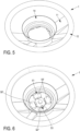
Fig. 5 is a perspective view of the steering wheel of the steering wheel arrangement ofFigure 1 , -
Fig. 6 is a view similar toFigure 5 , when the coupling mechanism ofFigure 4 is coupled to the steering wheel, -
Fig. 7 is a perspective view of a steering wheel arrangement according to a second embodiment of the invention, -
Fig. 8 is an exploded view of the steering wheel arrangement ofFigure 7 , -
Fig. 9 is a perspective view of the housing of the steering wheel arrangement ofFigure 7 , -
Fig. 10 is a perspective view of the coupling mechanism that causes rotation of the steering shaft in the steering wheel arrangement ofFigure 7 , -
Fig. 11 is a perspective view of the steering wheel of the steering wheel arrangement ofFigure 7 , and -
Fig. 12 is a view similar toFigure 11 , when the coupling mechanism ofFigure 10 is coupled to the steering wheel. -
Figures 1 and2 illustrate a first embodiment of a steering wheel arrangement according to the invention. In this embodiment, thesteering wheel arrangement 10 comprises asteering wheel 1 rotatable about a rotation axis X, asteering shaft 2, astationary housing 3 covering at least partially thesteering shaft 2 and acoupling mechanism 5 adapted to couple thesteering wheel 1 to thesteering shaft 2, such that rotation of the steering wheel causes rotation of the steering shaft. Thecoupling mechanism 5 is disclosed in detail in the following paragraphs and by reference toFigures 3 to 6 . Thissteering wheel arrangement 10 is adapted to be mounted to the steering column (not shown) of a vehicle, an optional stalk set 7 being positioned between thehousing 3 and the steering column. - The
steering wheel arrangement 10 further comprises acentral console 4 disposed in the central area of thesteering wheel 1, aboveradial spokes 11 that connect anouter ring 12 to acentral crown 14, thecentral console 4 being partially received inside thecentral crown 14. Thiscentral console 4 may be used for various purposes and, in particular, may incorporate one or several accessories, such as amulti-information display unit 41 and anair bag module 42 as illustrated inFigures 1 and2 . Other accessories may be used in replacement to and in addition to these accessories. For example, thecentral console 4 may also include a horn pad. Other accessories, such asswitches 43, may be fixedly connected to or integral with left and right convex-shaped wings housing 3 that are radially disposed around thecentral crown 14, saidswitches 43 being electrically connected to a control unit (not shown) viaelectrical wires 44. Otherelectrical wires 44 may be also provided to supply current to theair bag module 42. - The
central console 4 is fixedly connected to thestationary housing 3 through any conventional connecting means. Thus, when thesteering wheel 1 rotates, thecentral console 4 remains stationary. This stationary position of thecentral console 4 allows the information displayed by themulti-information display unit 41 to be always visible to the driver whatever the angular position of the steering wheel. In the same way, the stationary position of theair bag module 42 allows the air bag to be always in the best position to guarantee maximum safety for the driver. Furthermore, this non-rotatingair bag module 42 avoids the addition of a clock-spring rotor on which thewires 44 are mounted, said clock-spring rotor following the rotation of the air bag module in the prior art steering wheels. -
Figure 3 is an enlarged view of thehousing 3 that is illustrated inFigure 2 , theswitches 43 and thewires 44 being not shown. Thishousing 3 comprises anupper part 31 and alower part 33 connected by asingle crosspiece 32. Theupper part 31 includes acentral base 312, which is substantially flat and circular, and which is aligned in a plane perpendicular to the axis X. Thewings switches 43 protrude upwards from two radially opposite peripheral edges of thecentral base 312. Thelower part 33 comprises aproximal portion 331 and adistal portion 332, theproximal portion 331 being closer to theupper part 31 than thedistal portion 332. Theproximal portion 331 has an annular shape and is connected to thecentral base 312 of theupper part 31 by thecrosspiece 32, saidcrosspiece 32 being adapted to maintain a constant axial spacing between saidcentral base 312 and an upperperipheral edge 334 of saidproximal portion 331. Thedistal portion 332 has a parallelepiped shape and comprises an octagonalupper face 333 that is contiguous to theproximal portion 331 and eightside faces 335, four of which being provided withrectangular openings 336 through which the stalks of the stalk set 7 protrude. Thecrosspiece 32 extends between anupper end 321, which is defined by a straight end edge of thecentral base 312 of theupper part 31, and alower end 322, which is defined by a hemispherical portion of the upperperipheral edge 334 of theproximal portion 331. Thecrosspiece 32 comprises a firstplanar section 323 aligned in an axial direction and a secondplanar section 324 perpendicular to the firstplanar section 323, the firstplanar section 323 being integral with theupper part 31 along theupper end 321 and the secondplanar section 324 being integral with thelower part 33 along thelower end 322. - As illustrated in
Figure 3 by means of a broken line, the internal periphery of theproximal portion 331 is provided with agroove 34 that defines a closed path. Thegroove 34 includes anupper section 341 and alower section 342, said upper andlower sections intermediate sections 343 extending obliquely relative the respective planes define by said upper andlower sections lower section 342 is axially aligned with thelower end 322 of thecrosspiece 32. As explained in detail in the following paragraphs, thisgroove 34 defines the path followed bycoupling elements 50 of thesteering wheel arrangement 10 during the rotation of the steering wheel. In particular, theupper section 341 of thegroove 34 is adapted to define an upper position of saidcoupling elements 50 and thelower section 342 is adapted to define a lower position of saidcoupling elements 50. More specifically, thegroove 34 is configured such that, when thecoupling elements 50 are in their lower position, they are axially positioned below thecrosspiece 32, and, when thecoupling elements 50 are in their upper position, they are aligned with thecrosspiece 32 in a plane perpendicular to the rotation axis X. -
Figure 4 is an enlarged view of thecoupling mechanism 5 that is illustrated inFigure 2 . Thiscoupling mechanism 5 comprises fourcoupling elements 50 disposed around thesteering shaft 2 at regular angular intervals. Eachcoupling element 50 is formed of a substantially flat andcircular base 52 and of two coupling teeth, respectively adistal coupling tooth 51 and aproximal coupling tooth 53, projecting axially from saidbase 52, the height of theproximal tooth 53 being greater than the height of thedistal tooth 51. Thedistal coupling tooth 51 and theproximal coupling tooth 53 of eachcoupling element 50 are aligned in a radial direction. The steeringshaft 2 comprises anaxle 21 defining the rotation axis X and a disc-shapedtray 22 coaxially mounted on theaxle 21. Thetray 22 is provided with a series of fourproximal notches 23 on its outer periphery, eachproximal notch 23 being configured to slidably receive theproximal tooth 53 of one of thecoupling elements 50. Thus, a torque can be transmitted to thesteering shaft 2 when thecoupling elements 50 rotate or, inversely, a torque can be transmitted to thecoupling elements 50 when thesteering shaft 2 rotates. Theproximal tooth 53 axially moves inside thenotch 23 depending on the position of thecoupling element 50. This position results from the engagement of ahemispherical tab 54 protruding from an external side of thedistal coupling tooth 51 of thecoupling element 50 inside thegroove 34 of thehousing 3. Thus, when thetab 54 follows the path defined by theupper section 341 of thegroove 34, thecoupling element 50 is in its upper position, and, when thetab 54 follows the path defined by thelower section 342 of thegroove 34, thecoupling element 50 is in its lower position. In this lower position, thecoupling element 50 is positioned below thecrosspiece 32, thus avoiding a restriction in the movement of thecoupling element 50 due to the presence of thecrosspiece 32 against which thecoupling element 50 would abut if it were kept constantly in its upper position. The specific path defined by thegroove 34 thus allows a 360° rotation of thecoupling element 50 about the rotation axis X. - The rotation of the
coupling elements 50 results from the rotation of thesteering wheel 1. Indeed, as illustrated inFigures 5 and 6 , thecentral crown 14 of thesteering wheel 1 is provided with a series of four distal notches 16, each distal notch 16 being defined by a pair of adjacent segments 15 protruding from the inner periphery 13 of thecentral crown 14. Each distal notch 16 is configured to receive thedistal coupling tooth 51 of thecoupling elements 50 when saidcoupling elements 50 are in their upper position (corresponding to the position of the coupling elements 50' illustrated inFigure 6 ), thus ensuring the transmission of a torque to saidcoupling element 50 when thesteering wheel 1 rotates. When thecoupling elements 50 are in their lower position (corresponding to the position of thecoupling element 50" illustrated inFigure 6 ), thisdistal tooth 51 is out of the distal notch 16, but, due to its greater height, theproximal tooth 53 is still received in theproximal notch 23. Thus, in this lower position, the torque generated by thesteering wheel 1 is not transmitted to thecoupling element 50". However, thecoupling element 50" rotates due to the engagement of theproximal tooth 53 in theproximal notch 23 that transmits the torque generated by the steeringshaft 2 under the action of the coupling elements 50'. In the embodiment shown, thesteering wheel arrangement 1 is configured such that at least threecoupling elements 50 are in their upper position whatever the angular position ofsteering wheel 1. In alternative embodiments of the present invention, thesteering wheel arrangement 1 may comprise only threecoupling elements 50 or more than fourcoupling elements 50. In further alternative embodiments of the present invention, thegroove 34 may comprise two or morelower sections 342, eachlower section 342 being axially aligned with acorresponding crosspiece 32 of thehousing 3 that connect the upper andlower parts -
Figures 7 and8 illustrate a second embodiment of a steering wheel arrangement according to the invention. The elements of this second embodiment having a similar function and design to those of the first embodiment hold the same reference numbers. In this embodiment, thesteering wheel arrangement 10 comprises asteering wheel 1 rotatable about a rotation axis X, asteering shaft 2, astationary housing 3 covering at least partially thesteering shaft 2 and acoupling mechanism 6 adapted to couple thesteering wheel 1 to thesteering shaft 2, such that rotation of the steering wheel causes rotation of the steering shaft. Thecoupling mechanism 6 is disclosed in detail in the following paragraphs and by reference toFigures 9 to 12 . Thissteering wheel arrangement 10 is adapted to be mounted to the steering column (not shown) of a vehicle, an optional stalk set 7 being positioned between thehousing 3 and the steering column. - The
steering wheel arrangement 10 further comprises acentral console 4 disposed in the central area of thesteering wheel 1, aboveradial spokes 11 that connect anouter ring 12 to an annularcentral crown 14, thecentral console 4 being partially received inside thecentral crown 14. Thiscentral console 4 may be used for various purposes and, in particular, may incorporate one or several accessories, such as anair bag module 42 andelectrical wires 44 adapted to supply current to theair bag module 42. - The
central console 4 is fixedly connected to thestationary housing 3 through any conventional connecting means. Thus, when thesteering wheel 1 rotates, thecentral console 4 remains stationary. This stationary position of thecentral console 4 allows theair bag module 42 to be always in the best position to guarantee maximum safety for the driver. This non-rotatingair bag module 42 is fixedly connected to a clock-spring stator 45 on which thewires 44 are mounted, said clock-spring stator 45 being housed inside thecentral crown 14. Anannular ball bearing 46 coaxially mounted between thecentral crown 14 and thehousing 3 allows the rotation of thesteering wheel 1 with respect to thehousing 3 about the rotation axis X. -
Figure 9 is an enlarged view of thehousing 3 that is illustrated inFigure 8 . Thishousing 3 comprises anupper part 31 and alower part 33 connected by acrosspiece 32. Theupper part 31 includes acentral base 312, which is substantially flat and rectangular, and which is aligned in a plane perpendicular to the axis X. Thelower part 33 comprises aproximal portion 331 and adistal portion 332, theproximal portion 331 being closer to theupper part 31 than thedistal portion 332. Theproximal portion 331 has an annular shape and is connected to thecentral base 312 of theupper part 31 by thecrosspiece 32, said crosspiece 32 being adapted to maintain a constant axial spacing between saidcentral base 312 and an upperperipheral edge 334 of saidproximal portion 331. Thedistal portion 332 has a parallelepiped shape and comprises an octagonalupper face 333 that is contiguous to theproximal portion 331 and eight side faces 335, three of which being provided withrectangular openings 336 through which the stalks of the stalk set 7 protrude. Thecrosspiece 32 comprises twoplanar sections 324 perpendicular to the axial direction and, contiguous thereto, a substantiallyannular section 325 aligned in an axial direction. Eachplanar section 324 is integral with thelower part 33 along alower end 322, which is defined by a hemispherical portion of the upperperipheral edge 334 of theproximal portion 331. The substantiallyannular section 325 is connected to theupper part 31 through fourpillars 326 extending along an axial direction. Eachpillar 326 is integral with theupper part 31 at anupper end 321. - As illustrated in
Figure 9 by means of a broken line, the internal periphery of theproximal portion 331 is provided with agroove 34 that defines a closed path. Thegroove 34 includes twoupper sections 341 and twolower sections 342, said upper andlower sections upper section 341 is linked to thelower sections 342 by twointermediate sections 343 extending obliquely relative the respective planes define by said upper andlower sections lower section 342 is axially aligned with onelower end 322 of thecrosspiece 32. As explained in detail in the following paragraphs, thisgroove 34 defines the path followed by couplingelements 60 of thesteering wheel arrangement 10 during the rotation of the steering wheel. In particular, eachupper section 341 of thegroove 34 is adapted to define an upper position of saidcoupling elements 60 and eachlower section 342 is adapted to define a lower position of saidcoupling elements 60. More specifically, thegroove 34 is configured such that, when thecoupling elements 60 are in their lower positions, they are axially positioned below thecrosspiece 32, and, when thecoupling elements 60 are in their upper position, they are aligned with thecrosspiece 32 in a plane perpendicular to the rotation axis X. -
Figure 10 is an enlarged view of thecoupling mechanism 6 that is illustrated inFigure 8 . Thiscoupling mechanism 6 comprises fourcoupling elements 60 disposed around thesteering shaft 2 at regular angular intervals. Eachcoupling element 60 consists in an arc-shaped spindle comprising acentral ring 63 and two distal coupling pins, respectively a left coupling pin 61' and aright coupling pin 61", connected to thecentral ring 63 through two curved arms, respectively a left arm 62' and aright arm 62". Thecentral ring 63 has a toothed inner periphery having a complementary form to the toothed outer periphery of thesteering shaft 2 such that thecentral ring 63 is coaxially mounted on thesteering shaft 2 when the teeth of thecentral ring 63 engage with the teeth of thesteering shaft 2. Thus, a torque can be transmitted to thesteering shaft 2 when thecoupling elements 60 rotate or, inversely, a torque can be transmitted to thecoupling elements 60 when thesteering shaft 2 rotates. Furthermore, this arrangement allows an axial movement of thecoupling element 60 relative to thesteering shaft 2. Thecentral ring 63 axially moves along the steeringshaft 2 depending on the position of thecoupling element 60. This position results from the engagement of two hemispherical tabs, respectively a left tab 64' and aright tab 64", protruding respectively from an external side of the left andright arms 62', 62" of thecoupling element 60 inside thegroove 34 of thehousing 3. Thus, when thetabs 64', 64" follow the path defined by theupper sections 341 of thegroove 34, thecoupling element 60 is in its upper position, and, when thetabs 64', 64" follow the path defined by thelower sections 342 of thegroove 34, thecoupling element 60 is in its lower position. In this lower position, thecoupling element 60 is positioned below thecrosspiece 32, thus avoiding a restriction in the movement of thecoupling element 60 due to the presence of thecrosspiece 32 against which thecoupling element 60 would abut if it were kept constantly in its upper position. The specific path defined by thegroove 34 thus allows a 360° rotation of thecoupling element 60 about the rotation axis X. - The rotation of the
coupling elements 60 results from the rotation of thesteering wheel 1. Indeed, as illustrated inFigures 11 and 12 , thecentral crown 14 of thesteering wheel 1 is provided at itsbottom face 141, which faces thehousing 3, with a series of eight axially orientedapertures 18. Theapertures 18 are configured to receive the coupling pins 61', 61" of thecoupling elements 60 when thecoupling elements 60 are in their upper position (corresponding to the position of the coupling element 60' illustrated inFigure 12 ), thus ensuring the transmission of a torque to saidcoupling element 60 when thesteering wheel 1 rotates. When thecoupling elements 60 are in their lower position (corresponding to the position of thecoupling elements 60" illustrated inFigure 12 ), their coupling pins 61', 61" are out of theapertures 18. Thus, in this lower position, the torque generated by thesteering wheel 1 is not transmitted to thecoupling elements 60". However, thecoupling elements 60" rotate due to the gear engagement of theircentral ring 63 with thesteering shaft 2. In the embodiment shown, thesteering wheel arrangement 1 is configured such that at least onecoupling element 60 is in its upper position whatever the angular position ofsteering wheel 1. In alternative embodiments of the present invention, thesteering wheel arrangement 1 may comprise only threecoupling elements 60 or more than fourcoupling elements 60. In further alternative embodiments of the present invention, thegroove 34 may comprise only onelower section 342 or three or morelower sections 342, eachlower section 342 being axially aligned with acorresponding crosspiece 32 of thehousing 3 that connect together the upper andlower parts - It is to be understood that the present invention is not limited to the embodiments described above and illustrated in the drawings; rather, the skilled person will recognize that many changes and modifications may be made within the scope of the appended claims.
Claims (15)
- A steering wheel arrangement (10), comprising:- a steering wheel (1) rotatable about a rotation axis (X),- a steering shaft (2),- a stationary housing (3) covering at least partially the steering shaft (2) and supporting at least one accessory (41, 42, 43),- a plurality of coupling elements (50, 60) adapted to couple the steering wheel (1) to the steering shaft (2), such that rotation of the steering wheel causes rotation of the steering shaft,characterized in that each coupling element (50, 60) is integral in rotation with the steering shaft (2) and slidably movable along an axial direction between an upper position and a lower position, and in that each coupling element (50, 60) is detachably connected to the steering wheel (1), each coupling element (50, 60) being connected to the steering wheel (1) in its upper position, such that rotation of the steering wheel (1) causes rotation of the coupling element (50, 60), and being disconnected from the steering wheel (1) in its lower position, such that rotation of the steering wheel (1) does not cause rotation of the coupling element (50, 60).
- The steering wheel arrangement (10) according to claim 1, wherein the housing (3) comprises an upper part (31) and a lower part (33), said upper and lower parts (31, 33) being connected by at least one crosspiece (32), the at least one crosspiece (32) being axially positioned above the coupling elements (50, 60) when said coupling elements (50, 60) are in their lower position, thus permitting a rotation of said coupling elements about the rotation axis, and the at least one crosspiece being aligned with the coupling elements (50, 60) in a plane perpendicular to the rotation axis (X) when said coupling elements (50, 60) are in their upper position.
- The steering wheel arrangement (10) according to claim 1 or claim 2, wherein each coupling element (50, 60) comprises a hemispherical tab (54, 64', 64"), said tab (54, 64', 64") being engaged inside a groove (34) of the housing (3), thus allowing the rotation of the coupling element (50, 60) about the rotation axis (X).
- The steering wheel arrangement (10) according to claim 3, wherein the groove (34) defines a closed path such that, when the tab (54, 64', 64") entirely follows said closed path, each coupling element (50, 60) rotates 360° around the rotation axis (X).
- The steering wheel arrangement (10) according to claim 3 or claim 4, wherein the groove (34) includes at least one upper section (341) and at least one lower section (342), said upper and lower sections (341, 342) being axially distant from each other, the at least one upper section (341) defining the upper position of the coupling elements (50, 60) and the at least one lower section (342) defining the lower position of the coupling elements (50, 60).
- The steering wheel arrangement (10) according to any claims 1 to 5, wherein each coupling element (50) is formed of a substantially flat and circular base (52) and of two teeth, respectively a distal tooth (51) and a proximal tooth (53), projecting axially from said base (52), said distal and proximal teeth (51, 53) being aligned in a radial direction, wherein the steering wheel (1) comprises a central crown (14), said central crown (14) being provided with a series of distal notches (16) on its inner periphery (13), each distal notch (16) being configured to receive the distal tooth (51) of one of the coupling elements (50) when said coupling element (50) is in its upper position, thus ensuring the transmission of a torque to said coupling element (50) when the steering wheel (1) rotates, said distal tooth (51) being out of said distal notch (16) when said coupling element (50) is in its lower position, and wherein the steering shaft (2) comprises a disc-shaped tray (22) provided with a series of proximal notches (23) on its outer periphery, each proximal notch (23) being configured to receive the proximal tooth (53) of one of the coupling elements (50) whatever the position of said coupling element, thus ensuring the transmission of a torque to the steering shaft (2) when the coupling element (50) rotates or vice versa.
- The steering wheel arrangement (10) according to claim 6, wherein the height of the proximal tooth (53) is greater than the height of the distal tooth (51), such that the proximal tooth (53) is still received in the proximal notch (23) in the lower position of the coupling element (50).
- The steering wheel arrangement (10) according to any claims 1 to 5, wherein the steering shaft (2) has a toothed outer periphery, wherein each coupling element (60) consists in an arc-shaped spindle comprising a central ring (63) and two distal pins, respectively a left pin (61') and a right pin (61"), connected thereto through two curved arms, respectively a left arm (62') and a right arm (62"), wherein the central ring (63) has a toothed inner periphery, said central ring (63) being coaxially mounted on the steering shaft (2) so that the teeth of the central ring (63) engage with the teeth of the steering shaft (2), thus ensuring the transmission of a torque to the steering shaft (2) when the coupling element (60) rotates or vice versa while allowing an axial movement of the coupling element (60) relative to the steering shaft (2), and wherein the steering wheel (1) comprises a central crown (14), said central crown (14) being provided with a series of axially oriented apertures (18) that are adapted to receive the left and right pins (61', 61") of the coupling elements (60) when the coupling elements are in their upper position, thus ensuring the transmission of a torque to said coupling elements (60) when the steering wheel (1) rotates, said left and right pins (61', 61") being out of said apertures (18) when the coupling elements are in their lower position.
- The steering wheel arrangement (10) according to any claims 1 to 8, wherein the at least one accessory (41, 42, 43) is fixedly connected to the housing (3).
- The steering wheel arrangement (10) according to any claims 1 to 9, wherein the at least one accessory (43) is integral with the housing (3).
- The steering wheel arrangement (10) according to any claims 6 to 9, wherein the central crown (14) at least partially houses the at least one accessory (41, 42).
- The steering wheel arrangement (10) according to claim 11, wherein the central crown (14) houses an annular support element (45), which is fixedly connected to the housing (3) and which supports electrical wires (44).
- The steering wheel arrangement (10) according to claim 12, further comprising an annular ball bearing (46) coaxially mounted between the central crown (14) and the housing (3), said ball bearing (46) allowing the rotation of the steering wheel (1) with respect to the housing (3) about the rotation axis (X).
- The steering wheel arrangement (10) according to any claims 1 to 13, wherein the at least one accessory is selected from the group consisting of a display unit (41), an airbag module (42), a switch (43) and a horn pad.
- A vehicle comprising a steering wheel arrangement (10) according to any claims 1 to 14.
Priority Applications (3)
| Application Number | Priority Date | Filing Date | Title |
|---|---|---|---|
| EP21212064.6A EP4190671A1 (en) | 2021-12-02 | 2021-12-02 | A steering wheel arrangement |
| CN202211527450.7A CN116215641A (en) | 2021-12-02 | 2022-12-01 | Steering wheel device |
| US18/061,179 US11780488B2 (en) | 2021-12-02 | 2022-12-02 | Steering wheel arrangement |
Applications Claiming Priority (1)
| Application Number | Priority Date | Filing Date | Title |
|---|---|---|---|
| EP21212064.6A EP4190671A1 (en) | 2021-12-02 | 2021-12-02 | A steering wheel arrangement |
Publications (1)
| Publication Number | Publication Date |
|---|---|
| EP4190671A1 true EP4190671A1 (en) | 2023-06-07 |
Family
ID=78821567
Family Applications (1)
| Application Number | Title | Priority Date | Filing Date |
|---|---|---|---|
| EP21212064.6A Pending EP4190671A1 (en) | 2021-12-02 | 2021-12-02 | A steering wheel arrangement |
Country Status (3)
| Country | Link |
|---|---|
| US (1) | US11780488B2 (en) |
| EP (1) | EP4190671A1 (en) |
| CN (1) | CN116215641A (en) |
Citations (2)
| Publication number | Priority date | Publication date | Assignee | Title |
|---|---|---|---|---|
| JPS5836743A (en) * | 1981-08-31 | 1983-03-03 | Tokai Rika Co Ltd | Mounting structure of switch base on handle |
| DE102004059551A1 (en) * | 2004-12-10 | 2006-06-22 | Leopold Kostal Gmbh & Co. Kg | Steering wheel arrangement for e.g. passenger car, has steering shaft connected with impact device in actuated manner such that device remains in its position, where device is fixed at shaft, which is rotatably supported at steering shaft |
Family Cites Families (11)
| Publication number | Priority date | Publication date | Assignee | Title |
|---|---|---|---|---|
| GB1216324A (en) * | 1967-06-26 | 1970-12-16 | Lucas Industries Ltd | Means for mounting controls in a road vehicle |
| US3548128A (en) * | 1969-07-11 | 1970-12-15 | Palmer B Willett | Adjustable steering wheel |
| DE2131902A1 (en) * | 1971-06-26 | 1972-12-28 | Heckler & Koch Gmbh | Steering wheel for a motor vehicle or the like. |
| JPS57198141A (en) * | 1981-05-29 | 1982-12-04 | Matsushita Electric Ind Co Ltd | Operation switch for car |
| JPS59156862A (en) * | 1983-02-25 | 1984-09-06 | Mazda Motor Corp | Steering device for car |
| DE4428883C1 (en) * | 1994-08-17 | 1995-12-14 | Kostal Leopold Gmbh & Co Kg | Steering column mounted electrical and optical switch device for road vehicle |
| US5855451A (en) * | 1997-04-21 | 1999-01-05 | General Motors Corporation | Coupling between steering wheel and steering shaft |
| US5855449A (en) * | 1997-06-09 | 1999-01-05 | General Motors Corporation | Coupling between steering shaft and steering wheel |
| JP2007530350A (en) * | 2004-03-25 | 2007-11-01 | ティムケン ユーエス コーポレーション | Handle mounting assembly |
| US7104821B2 (en) * | 2004-09-16 | 2006-09-12 | Alps Electric Co., Ltd. | Rotary connector |
| ITBO20140081U1 (en) * | 2014-09-30 | 2016-03-30 | I F R A S R L | AN ORGAN FOR THE CONTROL OF THE DIRECTION OF A VEHICLE, IN PARTICULAR OF A NAUTICAL VEHICLE. |
-
2021
- 2021-12-02 EP EP21212064.6A patent/EP4190671A1/en active Pending
-
2022
- 2022-12-01 CN CN202211527450.7A patent/CN116215641A/en active Pending
- 2022-12-02 US US18/061,179 patent/US11780488B2/en active Active
Patent Citations (2)
| Publication number | Priority date | Publication date | Assignee | Title |
|---|---|---|---|---|
| JPS5836743A (en) * | 1981-08-31 | 1983-03-03 | Tokai Rika Co Ltd | Mounting structure of switch base on handle |
| DE102004059551A1 (en) * | 2004-12-10 | 2006-06-22 | Leopold Kostal Gmbh & Co. Kg | Steering wheel arrangement for e.g. passenger car, has steering shaft connected with impact device in actuated manner such that device remains in its position, where device is fixed at shaft, which is rotatably supported at steering shaft |
Also Published As
| Publication number | Publication date |
|---|---|
| CN116215641A (en) | 2023-06-06 |
| US20230174134A1 (en) | 2023-06-08 |
| US11780488B2 (en) | 2023-10-10 |
Similar Documents
| Publication | Publication Date | Title |
|---|---|---|
| JPH0629028B2 (en) | Neutral position display device for electrically conductive winding cable in steering handle for vehicle | |
| JP4621316B2 (en) | Indicating instrument | |
| JP5097364B2 (en) | Rotation connector device with built-in rudder angle sensor | |
| US11407436B2 (en) | Steering wheel with fixed center | |
| US11780488B2 (en) | Steering wheel arrangement | |
| WO2008140633A1 (en) | Steering wheel assembly with centrally located stationary support member | |
| CN213323325U (en) | Vertical steering wheel of double round | |
| US20130276571A1 (en) | Advanced Steering Wheel | |
| US4625578A (en) | Steering wheel assembly | |
| CN102126434B (en) | Scale instrument | |
| US11673602B2 (en) | Steering wheel arrangement | |
| JPH01148640A (en) | Steering device for automobile | |
| CN101746405B (en) | Steering handle | |
| US3248965A (en) | Steering mechanism | |
| US20120144954A1 (en) | Advanced steering wheel | |
| JPS5940959A (en) | Switch device of steering gear | |
| KR100331424B1 (en) | indication device for steering position of vehicle | |
| US6290254B1 (en) | Steering wheel | |
| KR20170101663A (en) | Steering system for a car | |
| US6231074B1 (en) | Steering wheel | |
| JPH0523984B2 (en) | ||
| KR200289716Y1 (en) | Steering Wheel with jog dial switch | |
| JPS6332784Y2 (en) | ||
| EP1233887B1 (en) | Arrangement for a steering column | |
| GB2245346A (en) | Vehicle steering wheel and column assembly |
Legal Events
| Date | Code | Title | Description |
|---|---|---|---|
| PUAI | Public reference made under article 153(3) epc to a published international application that has entered the european phase |
Free format text: ORIGINAL CODE: 0009012 |
|
| STAA | Information on the status of an ep patent application or granted ep patent |
Free format text: STATUS: THE APPLICATION HAS BEEN PUBLISHED |
|
| AK | Designated contracting states |
Kind code of ref document: A1 Designated state(s): AL AT BE BG CH CY CZ DE DK EE ES FI FR GB GR HR HU IE IS IT LI LT LU LV MC MK MT NL NO PL PT RO RS SE SI SK SM TR |
|
| STAA | Information on the status of an ep patent application or granted ep patent |
Free format text: STATUS: REQUEST FOR EXAMINATION WAS MADE |
|
| 17P | Request for examination filed |
Effective date: 20231025 |
|
| RBV | Designated contracting states (corrected) |
Designated state(s): AL AT BE BG CH CY CZ DE DK EE ES FI FR GB GR HR HU IE IS IT LI LT LU LV MC MK MT NL NO PL PT RO RS SE SI SK SM TR |
|
| GRAP | Despatch of communication of intention to grant a patent |
Free format text: ORIGINAL CODE: EPIDOSNIGR1 |
|
| STAA | Information on the status of an ep patent application or granted ep patent |
Free format text: STATUS: GRANT OF PATENT IS INTENDED |
|
| INTG | Intention to grant announced |
Effective date: 20240306 |