EP4190575A1 - Printing device - Google Patents
Printing device Download PDFInfo
- Publication number
- EP4190575A1 EP4190575A1 EP21850643.4A EP21850643A EP4190575A1 EP 4190575 A1 EP4190575 A1 EP 4190575A1 EP 21850643 A EP21850643 A EP 21850643A EP 4190575 A1 EP4190575 A1 EP 4190575A1
- Authority
- EP
- European Patent Office
- Prior art keywords
- base plate
- printing device
- housing
- printed circuit
- circuit board
- Prior art date
- Legal status (The legal status is an assumption and is not a legal conclusion. Google has not performed a legal analysis and makes no representation as to the accuracy of the status listed.)
- Granted
Links
Images







Classifications
-
- B—PERFORMING OPERATIONS; TRANSPORTING
- B41—PRINTING; LINING MACHINES; TYPEWRITERS; STAMPS
- B41J—TYPEWRITERS; SELECTIVE PRINTING MECHANISMS, i.e. MECHANISMS PRINTING OTHERWISE THAN FROM A FORME; CORRECTION OF TYPOGRAPHICAL ERRORS
- B41J2/00—Typewriters or selective printing mechanisms characterised by the printing or marking process for which they are designed
- B41J2/315—Typewriters or selective printing mechanisms characterised by the printing or marking process for which they are designed characterised by selective application of heat to a heat sensitive printing or impression-transfer material
- B41J2/32—Typewriters or selective printing mechanisms characterised by the printing or marking process for which they are designed characterised by selective application of heat to a heat sensitive printing or impression-transfer material using thermal heads
- B41J2/325—Typewriters or selective printing mechanisms characterised by the printing or marking process for which they are designed characterised by selective application of heat to a heat sensitive printing or impression-transfer material using thermal heads by selective transfer of ink from ink carrier, e.g. from ink ribbon or sheet
-
- B—PERFORMING OPERATIONS; TRANSPORTING
- B41—PRINTING; LINING MACHINES; TYPEWRITERS; STAMPS
- B41J—TYPEWRITERS; SELECTIVE PRINTING MECHANISMS, i.e. MECHANISMS PRINTING OTHERWISE THAN FROM A FORME; CORRECTION OF TYPOGRAPHICAL ERRORS
- B41J2/00—Typewriters or selective printing mechanisms characterised by the printing or marking process for which they are designed
- B41J2/315—Typewriters or selective printing mechanisms characterised by the printing or marking process for which they are designed characterised by selective application of heat to a heat sensitive printing or impression-transfer material
- B41J2/32—Typewriters or selective printing mechanisms characterised by the printing or marking process for which they are designed characterised by selective application of heat to a heat sensitive printing or impression-transfer material using thermal heads
-
- B—PERFORMING OPERATIONS; TRANSPORTING
- B41—PRINTING; LINING MACHINES; TYPEWRITERS; STAMPS
- B41J—TYPEWRITERS; SELECTIVE PRINTING MECHANISMS, i.e. MECHANISMS PRINTING OTHERWISE THAN FROM A FORME; CORRECTION OF TYPOGRAPHICAL ERRORS
- B41J2/00—Typewriters or selective printing mechanisms characterised by the printing or marking process for which they are designed
- B41J2/315—Typewriters or selective printing mechanisms characterised by the printing or marking process for which they are designed characterised by selective application of heat to a heat sensitive printing or impression-transfer material
- B41J2/32—Typewriters or selective printing mechanisms characterised by the printing or marking process for which they are designed characterised by selective application of heat to a heat sensitive printing or impression-transfer material using thermal heads
- B41J2/335—Structure of thermal heads
- B41J2/33505—Constructional details
-
- B—PERFORMING OPERATIONS; TRANSPORTING
- B41—PRINTING; LINING MACHINES; TYPEWRITERS; STAMPS
- B41J—TYPEWRITERS; SELECTIVE PRINTING MECHANISMS, i.e. MECHANISMS PRINTING OTHERWISE THAN FROM A FORME; CORRECTION OF TYPOGRAPHICAL ERRORS
- B41J29/00—Details of, or accessories for, typewriters or selective printing mechanisms not otherwise provided for
- B41J29/02—Framework
-
- B—PERFORMING OPERATIONS; TRANSPORTING
- B41—PRINTING; LINING MACHINES; TYPEWRITERS; STAMPS
- B41J—TYPEWRITERS; SELECTIVE PRINTING MECHANISMS, i.e. MECHANISMS PRINTING OTHERWISE THAN FROM A FORME; CORRECTION OF TYPOGRAPHICAL ERRORS
- B41J29/00—Details of, or accessories for, typewriters or selective printing mechanisms not otherwise provided for
- B41J29/38—Drives, motors, controls or automatic cut-off devices for the entire printing mechanism
Definitions
- the present invention relates to a printing device.
- Patent Literature 1 discloses a printing device that performs printing on a printing medium such as a packaging material conveyed by a conveying machine.
- the printing device includes a thermal head and a partition wall which are fixed to a base plate.
- the partition wall partitions an area on a front side with respect to the base plate into an upper first area and a lower second area.
- the thermal head is disposed in the second area. The thermal head heats an ink ribbon and performs printing on a printing medium passing below the printing device.
- Patent Literature 1 JP2019-77109A
- An object of the present invention is to provide a printing device that allows an operator to easily perform various operations on a thermal head.
- a printing device includes: a base plate orthogonal to a first direction; a mounting portion provided rotatably on a surface, which is at one side in the first direction, of the base plate, in which a ribbon roll having an ink ribbon wound is to be mounted on the mounting portion; a thermal head provided on a surface, which is at the one side in the first direction, of the base plate, and configured to perform printing on a printing medium disposed on one side in a second direction orthogonal to the first direction; and a printed circuit board located on one side, with respect to the base plate, in a third direction orthogonal to the first direction and the second direction, and extending in a direction intersecting the base plate.
- the printed circuit board is not disposed on the other side in the second direction with respect to the thermal head. Therefore, the printing device can prevent the printed circuit board from becoming an obstacle in a case where an operator accesses the thermal head from the other side in the second direction to perform various operations. Therefore, the printing device can facilitate the operations performed on the thermal head by the operator.
- a first housing covering one side, in the first direction, of the base plate, the thermal head, and the printed circuit board may be further provided, and the printed circuit board may extend from an end portion, which is at the one side in the first direction, of the first housing to an other side in the first direction than the base plate.
- the printing device can use the printed circuit board as a transmission path of an electric signal transmitted from the end portion, which is at the one side in the first direction, of the first housing to the other side of the base plate in the first direction. In this case, it is not necessary to use a signal line or the like for transmitting an electric signal, and thus it is possible to reduce the cost of the printing device.
- a second housing covering an other side, in the first direction, of the base plate may be further provided, and an end portion, which is at the other side in the first direction, of the printed circuit board may be located on the one side in the first direction than an end portion, which is at an other side in the first direction, of the second housing.
- a connector or the like can be disposed in a portion between the end portion of the second housing on the other side in the first direction and the end portion of the printed circuit board on the other side in the first direction. In this case, it is possible to reduce a protrusion, of the connector or the like, toward the other side from the end portion of the second housing on the other side in the first direction.
- a cover covering the printed circuit board may be further provided.
- the printing device can reduce dust, dirt, and the like from adhering to the printed circuit board.
- the printed circuit board may be a relay board configured to relay an electric signal
- the printed circuit board may include, , a connector to which an external interface is to be connected, the connector provided on an end portion, which is at the one side in the first direction, of the printed circuit board, and the printed circuit board may be located on one side in the third direction with respect to a mounting area where the ribbon roll mounted on the mounting portion is to be disposed.
- the printing device can use the relay board as a transmission path for transmitting an electric signal received from the external interface connected to the connector.
- the ribbon roll can be attached to and detached from the mounting portion in a state where the external interface is connected to the connector.
- a sensor may be mounted on the printed circuit board, the sensor being configured to measure a driving amount of a drive portion provided on the one side, in the first direction, of the base plate.
- the printing device can easily hold the sensor by the printed circuit board.
- an LED may be mounted on the printed circuit board, the LED being configured to irradiate the one side, in the first direction, of the base plate with light.
- the printing device can easily hold the LED by the printed circuit board.
- a printing system 50 is a system for performing thermal transfer printing.
- the printing system 50 performs printing on a printing medium conveyed by an external device that is not shown.
- a specific example of the external device is a packaging machine that conveys a packaging material.
- the printing system 50 is used by being incorporated in a part of a conveyance line along which the printing medium is conveyed by the packaging machine.
- the printing system 50 includes a printing device 1 and a moving mechanism 5.
- an upper side, a lower side, a left side, a right side, a front side, and a rear side of each configuration included in the printing system 50 are defined.
- An upper side, a lower side, a left side, a right side, a front side, and a rear side of each of the printing device 1, the moving mechanism 5, and a ribbon cartridge 9, which will be described later, correspond to an upper side, a lower side, an obliquely upper left side, an obliquely lower right side, an obliquely lower left side, and an obliquely upper right side in FIG. 1 , respectively.
- FIG. 1 In FIG.
- a conveyance direction of the printing medium coincides with a left-right direction.
- the printing medium is conveyed from a right side to a left side below the printing device 1 by the external device (arrow Y1 (see FIGs. 1 and 2 )).
- the printing device 1 has a substantially rectangular parallelepiped shape.
- the ribbon cartridge 9 (see FIG. 4 ), which will be described later, is detachably mounted on the printing device 1.
- the printing device 1 feeds out an ink ribbon 9A (see FIG. 4 ) from a ribbon roll 90A (see FIG. 4 ) of the mounted ribbon cartridge 9, and heats the ink ribbon 9A by a thermal head 7A (see FIG. 5 and the like). Accordingly, the printing is performed on the printing medium conveyed below the printing device 1.
- the moving mechanism 5 includes a pair of frame bodies 51, a guide rail 52, and a holding portion 56.
- the pair of frame bodies 51 are separated from each other in a front-rear direction.
- Each frame body 51 includes an upper support portion 51A, a lower support portion 51B, and a pair of bridge portions 51C.
- Each of the upper support portion 51A and the lower support portion 51B has a prismatic shape and extends in the left-right direction.
- the upper support portion 51A and the lower support portion 51B are separated from each other in an up-down direction.
- the upper support portion 51A is disposed above the lower support portion 51B.
- the pair of bridge portions 51C each have a columnar shape and extend in the up-down direction.
- the pair of bridge portions 51C are bridged between both end portions of the upper support portion 51A and both end portions of the lower support portion 51B in the left-right direction.
- the guide rail 52 includes four columnar bodies extending in the front-rear direction.
- the respective columnar bodies are referred to as guide rails 52A, 52B, 52C, and 52D.
- the guide rails 52A and 52B are bridged between the upper support portions 51A of the pair of frame bodies 51.
- the guide rail 52A is located on a left side with respect to the guide rail 52B.
- the guide rails 52C and 52D are bridged between the lower support portions 51B of the pair of frame bodies 51.
- the guide rail 52C is located on a left side with respect to the guide rail 52D.
- the holding portion 56 includes a device holding portion 56A and a platen holding portion 56B.
- Each of the device holding portion 56A and the platen holding portion 56B has a rectangular parallelepiped shape.
- Each of the device holding portion 56A and the platen holding portion 56B has two through holes penetrating in the front-rear direction.
- the guide rails 52A and 52B are inserted through the respective two through holes of the device holding portion 56A.
- the device holding portion 56A is supported to be movable in the front-rear direction with respect to the guide rails 52A and 52B.
- the guide rails 52C and 52D are inserted through the respective two through holes of the platen holding portion 56B.
- the platen holding portion 56B is supported to be movable in the front-rear direction with respect to the guide rails 52C and 52D.
- the device holding portion 56A has four through holes 57 penetrating in the up-down direction.
- a bolt 57A is inserted through each through hole 57 downward.
- the four bolts 57A connect the printing device 1 to the device holding portion 56A.
- a cutout portion 58 is provided at a rear end portion of the device holding portion 56A.
- the cutout portion 58 is formed in a central portion of a lower surface of the device holding portion 56A in a left-right direction.
- the platen holding portion 56B includes an upper surface having a flat plate shape, and holds the platen facing the thermal head 7A of the printing device 1 in a case where printing is performed.
- the platen holding portion 56B is not connected to the printing device 1, and the printing device 1 and the platen are held independently in the up-down direction with a predetermined gap between the printing device 1 and the platen.
- the printing device 1 is held by the guide rails 52A and 52B via the device holding portion 56A.
- the printing device 1 moves in the front-rear direction (arrow Y2) as the device holding portion 56A moves in the front-rear direction with respect to the guide rails 52A and 52B.
- the platen is held by the guide rails 52C and 52D via the platen holding portion 56B.
- the platen moves in the front-rear direction as the platen holding portion 56B moves in the front-rear direction with respect to the guide rails 52C and 52D.
- the ribbon cartridge 9 includes a base portion 91 and shafts 92A to 92E (see FIG. 4 , hereinafter, collectively referred to as a "shaft 92").
- the base portion 91 has a substantially square plate shape.
- a cutout 910 is formed in an upper left corner portion of the base portion 91.
- a handle 91A extending in the up-down direction is provided on a front surface of the base portion 91 and at a center of the base portion 91 in the left-right direction.
- the shafts 92A to 92E each extend rearward from a rear surface of the base portion 91.
- the shafts 92A to 92D each have a columnar shape and are spindles rotatable about a rotation shaft extending in the front-rear direction.
- the shaft 92E has a columnar shape and is fixed to the base portion 91.
- the shaft 92A is provided on an upper side, with respect to a center of the base portion 91, in the up-down direction and on a right side, with respect to the center of the base portion 91, in the left-right direction.
- the shaft 92D is provided on the upper side, with respect to the center of the base portion 91, in the up-down direction and on a left side, with respect to the center of the base portion 91, in the left-right direction.
- the shafts 92A and 92D are arranged in the left-right direction.
- a spool 921 to which one end side of the ink ribbon 9A is connected is mounted on the shaft 92A.
- a spool 922 to which an other end side of the ink ribbon 9A is connected is mounted on the shaft 92D.
- the ink ribbon 9A is wound in a roll shape around each of the spool 921 mounted on the shaft 92A and the spool 922 mounted on the shaft 92D.
- the ink ribbon 9A wound around the spool 921 in a roll shape is referred to as the "ribbon roll 90A”.
- the ink ribbon 9A wound around the spool 922 in a roll shape is referred to as a "ribbon roll 90B".
- the ink ribbon 9A is fed out from the ribbon roll 90A and wound around the ribbon roll 90B.
- the shaft 92B is provided on a lower right corner of the base portion 91.
- a hole 923 is formed in a tip end of the shaft 92B.
- the shaft 92C is provided on a lower left corner of the base portion 91.
- An engaging gear 924 is provided on a tip end of the shaft 92C.
- the ink ribbon 9A stretched between the spools 921 and 922 comes into contact with a part of a peripheral surface of each of the shafts 92B and 92C.
- the shaft 92E is provided on an upper end portion of the base portion 91 and at the center of the base portion 91 in the left-right direction.
- the ribbon cartridge 9 is attachable to and detachable from the printing device 1. For example, as shown in FIG. 3 , a user grips the handle 91A of the ribbon cartridge 9 and slides the ribbon cartridge 9 forward with respect to the printing device 1 (arrow Y3). Accordingly, the ribbon cartridge 9 is detached from the printing device 1. On the other hand, for example, the user grips the handle 91A of the ribbon cartridge 9 and slides the ribbon cartridge 9 rearward with respect to the printing device 1 (arrow Y4). Accordingly, the ribbon cartridge 9 is mounted on the printing device 1.
- the printing device 1 includes a housing 11.
- the housing 11 includes a first housing 12 and a second housing 13.
- the first housing 12 covers an area, on a front side with respect to a base plate 21 (see FIG. 5 ) that will be described later, of the printing device 1. This area accommodates a mounting portion 22 (see FIG. 5 ), the thermal head 7A (see FIG. 5 ), a moving mechanism 7B (see FIG. 5 ), a relay board 42 (see FIG. 6 ), and the like, which will be described later.
- the second housing 13 covers an area, on a rear side with respect to the base plate 21, of the printing device 1. This area accommodates a motor 31 (see FIG. 10 ), a cover 6 (see FIG. 11 ), a control board 41 (see FIG. 12 ), and the like, which will be described later.
- the first housing 12 includes partial housings 12U, 12L, 12R, 12B, and 12C each having a plate shape.
- the partial housing 12U is orthogonal to the up-down direction and extends in the left-right direction.
- the partial housing 12L is orthogonal to the left-right direction and extends downward from a left end portion of the partial housing 12U.
- the partial housing 12B is orthogonal to the up-down direction and extends rightward from a lower end portion of the partial housing 12L.
- the partial housing 12R is orthogonal to the left-right direction and extends downward from a right end portion of the partial housing 12U.
- the partial housing 12C is orthogonal to the up-down direction and extends leftward from a lower end portion of the partial housing 12R. As shown in FIG. 5 , rear end portions of the partial housings 12U, 12L, 12R, 12B, and 12C are connected to the base plate 21, which will be described later.
- Front end portions of the partial housings 12U, 12L, 12R, 12B, and 12C form an opening 12P.
- the ribbon cartridge 9 (see FIG. 4 ) is mounted on the printing device 1 by being inserted inside the first housing 12 through the opening 12P of the first housing 12.
- a shape of the base portion 91 (see FIG. 4 ) of the ribbon cartridge 9 is substantially the same as a shape of the opening 12P.
- an area inside the first housing 12 where the ribbon cartridge 9 mounted on the printing device 1 is disposed is referred to as a mounting area 90.
- a right end portion of the partial housing 12B and a left end portion of the partial housing 12C form an opening 12Q.
- the thermal head 7A which will be described later, heats the ink ribbon 9A (see FIG. 4 ) of the mounted ribbon cartridge 9 to perform printing in a state of protruding downward from the opening 12Q.
- the second housing 13 includes partial housings 13U (see FIG. 3 ), 13L (see FIG. 3 ), 13R (see FIG. 5 ), 13B (see FIG. 5 ), and ? (see FIG. 2 ) each having a plate shape.
- the partial housing 13S has a square shape and is orthogonal to the front-rear direction.
- the partial housing 13U is orthogonal to the up-down direction and extends forward from an upper end portion of the partial housing 13S.
- the partial housing 13L is orthogonal to the left-right direction and extends forward from a left end portion of the partial housing 13S.
- the partial housing 13L is located on a right side with respect to the partial housing 12L of the first housing 12.
- the partial housing 13R is orthogonal to the left-right direction and extends forward from a right end portion of the partial housing 13S.
- the partial housing 13B is orthogonal to the up-down direction and extends forward from a lower end portion of the partial housing 13S.
- Front end portions of the partial housings 13U, 13R, and 13B are connected to the base plate 21, which will be described later.
- an opening 13P is formed substantially at a center of the partial housing 13U in the left-right direction.
- a fan 81 which will be described later, is exposed from the opening 13P.
- An opening 13Q is formed in a front end portion of the partial housing 13L.
- a part of the cover 6, which will be described later, is exposed to the outside through the opening 13Q from the inside of the second housing 13.
- the base plate 21 of the printing device 1 has a substantially square plate shape.
- the base plate 21 is orthogonal to the front-rear direction.
- the base plate 21 includes the mounting portion 22 (22A to 22E), the thermal head 7A, the moving mechanism 7B, and the like.
- the mounting portion 22 is provided on a front surface of the base plate 21.
- the shafts 92A to 92E (see FIG. 4 ) of the ribbon cartridge 9 are connected to the mounting portions 22A to 22E, respectively.
- the mounting portion 22A is provided on an upper side, with respect to a center of the base plate 21, in the up-down direction and on a right side, with respect to a center of the base plate 21, in the left-right direction.
- the mounting portion 22D is provided on the upper side, with respect to the center of the base plate 21, in the up-down direction and on a left side, with respect to the center of the base plate 21, in the left-right direction.
- the mounting portions 22A and 22D each have a circular shape and are arranged in the left-right direction.
- the ribbon roll 90A wound around the spool 921 (see FIG. 4 ) connected to the shaft 92A is mounted on the mounting portion 22A.
- the ribbon roll 90B (see FIG. 4 ) wound around the spool 922 connected to the shaft 92D is mounted on the mounting portion 22D.
- the mounting portion 22B is provided on a lower right corner of the base plate 21.
- the mounting portion 22B has a columnar shape and extends forward from the base plate 21.
- the mounting portion 22C is provided on a lower left corner of the base plate 21.
- the mounting portion 22C has a cylindrical shape and includes an engaging gear that is not shown inside the mounting portion 22C.
- the mounting portion 22E is provided on an upper end portion of the base plate 21 and at the center of the base plate 21 in the left-right direction.
- the mounting portion 22E has a tubular shape and extends forward from the base plate 21.
- the mounting portion 22B is inserted through the hole 923 (see FIG. 4 ) of the shaft 92B.
- the engaging gear of the mounting portion 22C is engaged with the engaging gear 924 (see FIG. 4 ) of the shaft 92C.
- the shaft 92E is inserted through a tubular interior of the mounting portion 22E.
- a rotation shaft of a motor 31A (see FIG. 9 ), which will be described later, is connected to the mounting portion 22A from behind.
- the mounting portion 22A rotates in accordance with rotation of the motor 31A.
- a rotation shaft of a motor 31B (see FIG. 9 ), which will be described later, is connected to the mounting portion 22D.
- the mounting portion 22D rotates in accordance with rotation of the motor 31B.
- the ink ribbon 9A (see FIG. 4 ) of the ribbon cartridge 9 is guided in a state of coming into contact with the shafts 92B and 92C between the spools 921 and 922 (see FIG. 4 ) to be conveyed in the printing device 1.
- the thermal head 7A is provided on a lower end portion of the front surface of the base plate 21 and at a portion between the mounting portions 22B and 22C.
- the thermal head 7A is supported to be movable in the up-down direction and the left-right direction with respect to the base plate 21.
- the thermal head 7A is a line thermal head.
- the thermal head 7A includes a base portion 71, a rail 72, and a plurality of heating elements 71A.
- the thermal head 7A is connected to a belt 32A connected to a pulley 32 connected to the rotation shaft of the motor 31B (see FIG. 10 ), which will be described later.
- the thermal head 7A moves in the left-right direction as the belt 32A is rotated by the motor 31B.
- the base portion 71 has an elongated plate shape and extends in the front-rear direction.
- the base portion 71 is inclined with respect to a direction orthogonal to the up-down direction.
- the base portion 71 is biased upward by a spring 71B (see FIG. 6 ).
- the rail 72 extending in the front-rear direction is provided on an upper side of the base portion 71.
- the plurality of heating elements 71A arranged in the front-rear direction are provided on a lower side of the base portion 71.
- the plurality of heating elements 71A come into contact, from above, with a portion of the ink ribbon 9A (see FIG. 4 ) fed out from the ribbon roll 90A of the ribbon cartridge 9 in accordance with the rotation of the mounting portions 22A and 22D, the portion being stretched between the shafts 92B and 92C (see FIG. 2 ).
- the plurality of heating elements 71A sandwich the ink ribbon 9A and the printing medium between the plurality of heating elements 71A and the platen held on the upper surface of the platen holding portion 56B.
- the plurality of heating elements 71A heat the ink ribbon 9A while pressing the ink ribbon 9A against the printing medium. Accordingly, the thermal head 7A transfers an ink of the ink ribbon 9A to the printing medium to perform the printing.
- the moving mechanism 7B is provided on the front surface of the base plate 21 and above the thermal head 7A.
- the moving mechanism 7B is a mechanism for moving the thermal head 7A in the up-down direction and the left-right direction.
- the moving mechanism 7B includes a pair of support portions 75, guide rails 76A, 76B, and 76C, and a swinging member 77.
- the pair of support portions 75 are provided above the mounting portions 22B and 22C, and are separated from each other in the left-right direction.
- the pair of support portions 75 are supported by the base plate 21 to be swingable about a rotation shaft extending in the left-right direction.
- the guide rails 76A, 76B, and 76C each have a columnar shape and extend in the left-right direction.
- the guide rails 76A, 76B, and 76C are bridged between the pair of support portions 75.
- an arm 33 is connected to the guide rail 76B.
- the arm 33 extends rearward from the guide rail 76B, passes through an opening 21A formed in the base plate 21, and extends to the rear of the base plate 21.
- the opening 21A allows the front and the rear of the base plate 21 to communicate with each other.
- a filter 210 for preventing passage of dust and dirt is provided in the opening 21A.
- the filter 210 is flexible and does not interfere with movement of the arm 33.
- a rear end portion of the arm 33 is connected to a crank 34 connected to a rotation shaft of a motor 31C, which will be described later.
- the arm 33 is driven as the crank 34 is rotated by the motor 31C.
- the pair of support portions 75 and the guide rails 76A, 76B, and 76C swing as the arm 33 is driven.
- the swinging member 77 is supported to be movable in the left-right direction with respect to the guide rail 76C.
- the swinging member 77 includes a first portion 77A extending obliquely downward and forward from the guide rail 76C, and a second portion 77B extending obliquely upward and forward from the guide rail 76C.
- a pulley 77C is rotatably supported at a tip end of the first portion 77A. The pulley 77C comes into contact with the rail 72 of the thermal head 7A from above.
- the pulley 77C moves the swinging member 77 in the left-right direction in accordance with the movement of the thermal head 7A in the left-right direction.
- a rotational body 77D is rotatably supported at a tip end of the second portion 77B. The rotational body 77D comes into contact with the guide rail 76A from the front.
- the swinging member 77 swings in conjunction with swinging of the pair of support portions 75 and the guide rails 76A, 76B, and 76C.
- the first portion 77A of the swinging member 77 pushes the thermal head 7A downward via the pulley 77C.
- the thermal head 7A moves downward against a biasing force of the spring 71B.
- the plurality of heating elements 71A of the thermal head 7A slightly protrude downward from the opening 12Q (see FIG. 5 ) of the housing 11.
- the thermal head 7A moves upward in accordance with the biasing force of the spring 71B.
- the plurality of heating elements 71A of the thermal head 7A are located above the opening 12Q of the housing 11.
- the relay board 42 is provided on a left side of the base plate 21.
- the relay board 42 extends in a direction orthogonal to the base plate 21, that is, in a direction orthogonal to the left-right direction.
- the relay board 42 is a printed circuit board on which various devices are mounted.
- the relay board 42 may be described as being divided into a first portion 42A and a second portion 42B.
- the first portion 42A is a portion on an upper side, with respect to a center of the relay board 42, in the up-down direction.
- the second portion 42B is a portion on a lower side, with respect to the center of the relay board 42, in the up-down direction.
- the first portion 42A has a rectangular shape elongated in the front-rear direction. As shown in FIGs. 7 and 9 , positions of front end portions of the first portion 42A and the partial housing 12L of the first housing 12 in the front-rear direction coincide with each other. As shown in FIG. 9 , a rear end portion of the first portion 42A is located behind the base plate 21. That is, the first portion 42A extends from a front end portion of the first housing 12 to a position behind the base plate 21. A portion of the first portion 42A disposed on a front side with respect to the base plate 21 is located on a left side of the mounting area 90 where the ribbon cartridge 9 is to be mounted.
- an interface portion 43 is provided on the front end portion of the first portion 42A.
- the interface portion 43 includes a USB connector 43A and a push button 43B on a front surface of the interface portion 43.
- a USB memory that is not shown is connected to the USB connector 43A.
- the push button 43B is operated in a case where an instruction to the printing device 1 is input.
- the first portion 42A transmits, to the control board 41 (see FIG. 12 ) that will be described later, an electric signal received from the USB memory connected to the USB connector 43A and an electric signal indicating that the push button 43B is operated.
- the interface portion 43 is provided with a plurality of indicators formed of LEDs, and an operation state of the printing device 1, a remaining amount of the ribbon, and the like can be indicated to the user by colors and lighting patterns of the indicators. As shown in FIG. 3 , the interface portion 43 is adjacent to the cutout 910 of the base portion 91 in a state where the ribbon cartridge 9 (see FIG. 4 ) is mounted. Therefore, the front surface of the interface portion 43 is not covered by the base portion 91 even in a case where the ribbon cartridge 9 is mounted.
- the second portion 42B extends downward from a lower end portion of the first portion 42A and a center of the first portion 42A in the front-rear direction.
- a front end portion of the second portion 42B is located behind the front end portion of the first portion 42A.
- a rear end portion of the second portion 42B is located behind the base plate 21 (see FIG. 9 ).
- an encoder 74A is provided on a right surface of the second portion 42B. The encoder 74A measures a rotation amount of the pair of support portions 75 of the moving mechanism 7B.
- a CPU mounted on the control board 41 which will be described later, can detect a movement amount of the thermal head 7A in the up-down direction, based on the rotation amount detected by the encoder 74A. Further, an LED 74B is provided on the right surface of the second portion 42B. The LED 74B irradiates the area on the front side with respect to the base plate 21 with light. Due to the irradiation with the light, the vicinity of the mounting portion 22 becomes bright. Accordingly, the user can visually recognize a remaining amount of the ink ribbon 9A of the ribbon cartridge 9 and an operation state of the printing device 1 through a window that is not shown provided in the base portion 91. By turning on the LED 74B at the time of attaching/detaching the ribbon cartridge 9, it is also possible to help an attachment/detachment operation of the ribbon cartridge 9.
- a portion of the relay board 42 located on the front side than the base plate 21 is covered with a cover 16 except for a left surface of the relay board 42.
- a part of the relay board 42 is accommodated in a space between the partial housing 12L of the first housing 12 and the cover 16.
- a part of the cover 16 is transmissive and allows the light from the LED 74B to transmit through the part of the cover 16.
- a portion of the relay board 42 located on the rear side with respect to the base plate 21 is covered with the cover 6, which will be described later.
- a rear end portion of the relay board 42 is located on a front side than a rear end portion of the second housing 13.
- connectors 45A, 45B, and 45C are provided on the rear end portion of the relay board 42.
- motors 31A to 31D are provided on a rear surface of the base plate 21.
- the motor 31A is connected to a portion of the rear surface of the base plate 21 that is a rear side with respect to the mounting portion 22A (see FIGs. 5 to 7 ) on the front surface of the base plate 21.
- the motor 31D is connected to a portion of the rear surface of the base plate 21 that is a rear side with respect to the mounting portion 22D (see FIGs. 5 to 7 ) on the front surface of the base plate 21.
- the motors 31A and 31D are arranged in the left-right direction.
- the motor 31A is disposed on a right side with respect to the motor 31D. Rotation shafts of the motors 31A and 31D penetrate the base plate 21 from the rear surface toward the front surface, and are connected to the mounting portions 22A and 22D on the front surface, respectively.
- the motor 31A rotates the mounting portion 22A
- the motor 31D rotates the mounting portion 22D.
- a heat insulator 30A is provided between the motor 31A and the base plate 21.
- a heat insulator 30D is provided between the motor 31D and the base plate 21. The heat insulators 30A and 30D prevent the heat of the motors 31A and 31D from being transmitted to the base plate 21, respectively.
- the motor 31B is connected to a lower side of the rear surface of the base plate 21 with respect to the motor 31A.
- the motor 31C is connected to a lower side, with respect to the motor 31D, of the rear surface of the base plate 21.
- the rotation shaft of the motor 31B penetrates the base plate 21 from the rear surface toward the front surface, and is connected to the pulley 32 on the front side with respect to the base plate 21.
- the motor 31B rotates the pulley 32 to move the thermal head 7A in the left-right direction.
- the rotation shaft of the motor 31C extends rightward and is connected to the crank 34.
- the motor 31C rotates the crank 34 to move the thermal head 7A in the up-down direction.
- the control board 41 is disposed behind the motor 31 (see FIG. 10 ).
- the control board 41 is a printed circuit board on which various devices are mounted.
- the control board 41 is fixed, by spacers 41A, to a position separated rearward from the base plate 21.
- the control board 41 is orthogonal to the front-rear direction and parallel to the base plate 21.
- the CPU for controlling the motor 31, encoders for detecting rotation amounts of the respective motors 31A and 31D, and the like are mounted on the control board 41.
- the encoder for detecting the rotation amount of the motor 31A is provided on a front surface of the control board 41 and behind a rotation shaft 33A (see FIGs. 10 and 11 ) of the motor 31A.
- the encoder for detecting the rotation amount of the motor 31D is provided on the front surface of the control board 41 and behind a rotation shaft 33D (see FIGs. 10 and 11 ) of the motor 31D.
- the control board 41 is electrically connected to the relay board 42 by an FPC that is not shown.
- the cover 6 is disposed behind the base plate 21 and forward of the control board 41 (see FIG. 12 ).
- the cover 6 covers, from behind, the motors 31A to 31D and a part of the rear end portion of the relay board 42.
- the cover 6 includes partial covers 61S, 61U, 61B, 61R, 61L, 62U, 62S, 62B, and 62L each having a plate shape.
- the partial cover 61S has irregularities, and a main component of the partial cover 61S is orthogonal to the front-rear direction.
- the partial cover 61S is disposed between the motor 31 and the control board 41.
- the partial covers 61U, 61R, 61L, and 61B extend forward from an upper end portion, a right end portion, a left end portion, and a lower end portion of the partial cover 61S, respectively.
- the partial cover 62S extends leftward from a front end portion of the partial cover 61L and is orthogonal to the front-rear direction.
- the partial covers 62U, 62B, and 62L extend forward from an upper end portion, a lower end portion, and a left end portion of the partial cover 62S, respectively.
- the partial cover 62S is provided with a partition wall 62R extending forward from a front surface of the partial cover 62S.
- the partition wall 62R is orthogonal to the left-right direction and extends in the up-down direction. Rear end portions of the partial covers 61U, 61R, 61B, 62U, 62L, and 62B and the partition wall 62R are connected to the base plate 21.
- the cover 6 partitions the area covered by the second housing 13 (see FIGs. 2 and 3 , and the like) into a first area 66A, a second area 66B, and a third area 66C.
- the first area 66A is an area surrounded by the partial covers 61S, 61U, 61R, and 61B and the partition wall 62R.
- the motors 31A to 31D are disposed in the first area 66A.
- the third area 66C is an area surrounded by the partial covers 62S, 62U, 62L, 62B and the partition wall 62R. A part of the rear end portion of the relay board 42 is disposed in the third area 66C. As shown in FIG.
- the second area 66B is an area other than the first area 66A and the third area 66C in the area covered by the second housing 13 (see FIGs. 2 and 3 , and the like).
- the control board 41 is disposed in the second area 66B.
- the first area 661 and the second area 66B are arranged in the front-rear direction.
- an opening 61P is provided in the partial cover 61U.
- Through holes 63A and 63D are provided in the partial cover 61S.
- the rotation shaft 33A of the motor 31A is inserted through the through hole 63A from the front and protrudes rearward.
- the rotation shaft 33D of the motor 31D is inserted through the through hole 63D from the front and protrudes rearward.
- through holes 64A, 64B, and 64C are provided in the partial cover 62S.
- the connectors 45A and 45B provided on the relay board 42 are inserted through the through holes 64A and 64B from the front and protrude rearward, respectively.
- the connector 45C provided on the relay board 42 is exposed from the through hole 64C.
- a fan unit 8 is disposed in the opening 13P of the partial housing 13U corresponding to an upper end portion of the second housing 13.
- the fan unit 8 is fixed to the upper end portion of the base plate 21 and at the center of the base plate 21 in the left-right direction, and protrudes rearward.
- the fan unit 8 is located above the opening 61P provided in the partial cover 61U of the cover 6.
- the fan unit 8 includes the fan 81 and a fixing portion 82.
- the fan 81 includes a plurality of propellers and a hub to which the plurality of propellers are connected, and rotates about a rotation shaft extending in the up-down direction.
- a motor is built in the fan 81. In a case where the fan 81 rotates, air in the first area 66A of the cover 6 is discharged to the outside of the printing device 1 through the opening 61P of the cover 6 and the opening 13P (see FIG. 9 ) of the second housing 13.
- the fixing portion 82 has a C-shape when viewed from above, and covers a left side, a right side, and a rear side of the fan 81.
- the fixing portion 82 rotatably supports the fan 81 and fixes the fan 81 to the base plate 21.
- the fixing portion 82 includes a rectangular plate body 82P on an upper surface of the fixing portion 82.
- a front end portion of the plate body 82P is fixed to an upper side of the upper end portion of the base plate 21.
- Screw holes 82A extending in the up-down direction are formed at respective four corners of the base plate 21.
- a filter 85 for preventing passage of dust and dirt is provided in an opening inside the plate body 82P.
- the four bolts 57A inserted through the four through holes 57 of the device holding portion 56A are screwed into the respective four screw holes 82A of the fixing portion 82 shown in FIG. 3 .
- the printing device 1 is held by the device holding portion 56A by connecting the device holding portion 56A to the fixing portion 82 with the four bolts 57A.
- the device holding portion 56A covers the fan 81 from above in a state of being connected to the fixing portion 82.
- the ribbon cartridge 9 is mounted on the printing device 1.
- a printing surface of the printing medium conveyed by the external device and the thermal head 7A of the printing device 1 face each other in the up-down direction.
- a platen roller that is not shown is disposed on a side opposite to the printing device 1 with respect to the printing medium.
- the fan unit 8 is powered on, and the fan 81 starts to rotate. As shown in FIG. 8 , the fan 81 discharges, to the outside, the air in the first area 66A of the cover 6 from an upper end portion of the housing 11 (arrow Y13). The discharged air passes through a gap formed between the fan unit 8 and the cutout portion 58 of the device holding portion 56A connected to the fixing portion 82 of the fan unit 8. Accordingly, an upward air flow is formed inside the first area 66A (arrow Y12). In accordance with the air flow, air outside the housing 11 is taken into an area inside the housing 11 and on the front side of the base plate 21 through the opening 12Q (see FIG. 5 ) in the lower end portion of the housing 11 (arrow Y10). Further, the air taken into the area on the front side of the base plate 21 passes through the opening 21A of the base plate 21 to the rear side and flows into the first area 66A (arrow Y11).
- the mounting portions 22A and 22D rotate in accordance with driving of the motors 31A and 31D, respectively. Accordingly, the shafts 92A and 92F of the ribbon cartridge 9 connected to the respective mounting portions 22A and 22D also rotate.
- the ink ribbon 9A is fed out from the ribbon roll 90A of the spool 921 mounted on the shaft 92A, and is wound around the ribbon roll 90B of the spool 922 mounted on the shaft 92D.
- a portion of the ink ribbon 9A between the shafts 92B and 92C moves in the same direction as the conveyance direction of the printing medium.
- the motors 31A and 31D drive to generate heat.
- the air flow (arrow Y12) is generated inside the first area 66A. The air flow cools the motors 31A and 31D.
- the motor 31C is driven, and the thermal head 7A is lowered to protrude below the opening 12Q.
- the thermal head 7A comes into contact with the platen roller from above via the ink ribbon 9A and the printing medium.
- the ink ribbon 9A is pressed against the printing surface of the printing medium in accordance with the movement of the thermal head 7A.
- the heating elements 71A of the thermal head 7A generate heat, and the ink of the ink ribbon 9A is transferred to the printing surface of the printing medium. As described above, printing by the printing device 1 is performed.
- the thermal head 7A of the printing device 1 may be performed.
- the printing medium and the platen roller are arranged below the printing device 1, and thus usually, an operator often accesses the thermal head 7A from above the printing device 1 to perform various operations.
- the relay board 42 is disposed on the left side of the base plate 21, and the relay board 42 is not disposed above the thermal head 7A. Therefore, the printing device 1 can prevent the relay board 42 from becoming an obstacle in a case where the operator accesses the thermal head 7A from above to perform various operations. Therefore, the printing device 1 can facilitate various operations performed on the thermal head 7A by the operator.
- the relay board 42 extends from the front end portion of the first housing 12 to the rear side with respect to the base plate 21. Therefore, the printing device 1 can use the relay board 42 as a transmission path of an electric signal transmitted from the front end portion of the first housing 12 to the control board 41 behind the base plate 21. In this case, it is not necessary to use a signal line or the like for transmitting an electric signal, and thus it is possible to reduce the cost of the printing device 1.
- the rear end portion of the relay board 42 is located on the front side than the rear end portion of the second housing 13. Therefore, in the printing device 1, a connector on a cable side connected to the connectors 45A and 45B of the relay board 42 can be disposed in a portion between the rear end portion of the second housing 13 and the rear end portion of the relay board 42. In this case, it is possible to reduce a rearward protrusion, from the rear end portion of the second housing 13, of the connector on the cable side. Therefore, the printing device 1 can reduce a space in the front-rear direction required at the time of printing.
- the printing device 1 includes the cover 16 that covers the relay board 42.
- the cover 16 can reduce dust, dirt, and the like adhering to the relay board 42.
- the printing device 1 can use the relay board 42 as a transmission path for transmitting an electric signal received from a USB cable connected to the USB connector 43A of the interface portion 43.
- the relay board 42 is disposed on the left side with respect to the mounting area 90 of the ribbon cartridge 9, and thus the relay board 42 does not interfere with the attachment/detachment action of the ribbon cartridge 9 with respect to the printing device 1. Therefore, in a case where the ribbon cartridge 9 is attached to or detached from the printing device 1, it is not necessary to remove the USB cable from the USB connector 43A. Therefore, in the printing device 1, the ribbon cartridge 9 can be easily attached to and detached from the printing device 1 in a state where the USB cable is connected to the USB connector 43A.
- the encoder 74A provided on the right surface of the second portion 42B of the relay board 42 can detect the movement amount of the thermal head 7A in the up-down direction.
- the printing device 1 can easily hold the encoder 74A with the relay board 42.
- the LED 74B provided on the right surface of the second portion 42B of the relay board 42 can irradiate the front side of the base plate 21 with light.
- the printing device 1 can easily hold the LED 74B with the relay board 42.
- the relay board 42 may be provided on a right side of the base plate 21, or may be provided on both left and right sides of the base plate 21.
- the relay board 42 may include only the first portion 42A, and may not include the second portion 42B.
- the relay board 42 may include only the second portion 42B, and may not include the first portion 42A.
- a front end portion of the relay board 42 may be located behind the front end portion of the first housing 12. Positions of the rear end portion of the relay board 42 and the rear end portion of the second housing 13 in the front-rear direction may coincide with each other. In this case, the connector on the cable side connected to the connectors 45A and 45B of the relay board 42 may protrude rearward than the rear end portion of the second housing 13.
- the cover 16 covering a part of the relay board 42 may further cover a left side of the relay board 42.
- the cover 16 may be integrated with the first housing 12.
- the cover 16 may not be provided.
- the interface portion 43 may be provided on a left surface of the relay board 42.
- Various sensors that measures driving amounts of various drive mechanisms connected to the base plate 21 may be mounted on the relay board 42.
- an optical sensor that measures a ribbon amount of the ribbon rolls 90A and 90B, a contact sensor that detects whether the ribbon cartridge 9 is mounted, and the like may be mounted on the relay board 42.
- the number of LEDs 74B mounted on the relay board 42 is not limited to one, and may be plural.
- the encoder 74A and the LED 74B may not be mounted on the relay board 42.
- the front-rear direction is an example of a "first direction” in the present invention.
- the front side is an example of "one side in the first direction” in the present invention.
- the rear side is an example of "the other side in the first direction” in the present invention.
- the up-down direction is an example of a "second direction” in the present invention.
- the lower side is an example of "one side in the second direction” in the present invention.
- the left-right direction is an example of a "third direction” in the present invention.
- the left side is an example of "one side in the third direction” in the present invention.
- the relay board 42 is an example of a "printed circuit board" in the present invention.
Landscapes
- Electronic Switches (AREA)
- Accessory Devices And Overall Control Thereof (AREA)
Abstract
Description
- The present invention relates to a printing device.
-
Patent Literature 1 discloses a printing device that performs printing on a printing medium such as a packaging material conveyed by a conveying machine. The printing device includes a thermal head and a partition wall which are fixed to a base plate. The partition wall partitions an area on a front side with respect to the base plate into an upper first area and a lower second area. The thermal head is disposed in the second area. The thermal head heats an ink ribbon and performs printing on a printing medium passing below the printing device. - Patent Literature 1:
JP2019-77109A - In the above printing device, when various operations on the thermal head (for example, replacement of the thermal head) are performed, an operator accesses the thermal head from above the printing device. However, in this case, there is a problem in that the operability of the operator is poor because the partition wall becomes an obstacle. Therefore, it is preferable that various members constituting the printing device are not disposed above the thermal head in order to facilitate the operations of the operator.
- An object of the present invention is to provide a printing device that allows an operator to easily perform various operations on a thermal head.
- A printing device according to the present invention includes: a base plate orthogonal to a first direction; a mounting portion provided rotatably on a surface, which is at one side in the first direction, of the base plate, in which a ribbon roll having an ink ribbon wound is to be mounted on the mounting portion; a thermal head provided on a surface, which is at the one side in the first direction, of the base plate, and configured to perform printing on a printing medium disposed on one side in a second direction orthogonal to the first direction; and a printed circuit board located on one side, with respect to the base plate, in a third direction orthogonal to the first direction and the second direction, and extending in a direction intersecting the base plate.
- In the printing device according to the present invention, the printed circuit board is not disposed on the other side in the second direction with respect to the thermal head. Therefore, the printing device can prevent the printed circuit board from becoming an obstacle in a case where an operator accesses the thermal head from the other side in the second direction to perform various operations. Therefore, the printing device can facilitate the operations performed on the thermal head by the operator.
- In the present invention, a first housing covering one side, in the first direction, of the base plate, the thermal head, and the printed circuit board may be further provided, and the printed circuit board may extend from an end portion, which is at the one side in the first direction, of the first housing to an other side in the first direction than the base plate. The printing device can use the printed circuit board as a transmission path of an electric signal transmitted from the end portion, which is at the one side in the first direction, of the first housing to the other side of the base plate in the first direction. In this case, it is not necessary to use a signal line or the like for transmitting an electric signal, and thus it is possible to reduce the cost of the printing device.
- In the present invention, a second housing covering an other side, in the first direction, of the base plate may be further provided, and an end portion, which is at the other side in the first direction, of the printed circuit board may be located on the one side in the first direction than an end portion, which is at an other side in the first direction, of the second housing. In this case, in the printing device, a connector or the like can be disposed in a portion between the end portion of the second housing on the other side in the first direction and the end portion of the printed circuit board on the other side in the first direction. In this case, it is possible to reduce a protrusion, of the connector or the like, toward the other side from the end portion of the second housing on the other side in the first direction.
- In the present invention, a cover covering the printed circuit board may be further provided. The printing device can reduce dust, dirt, and the like from adhering to the printed circuit board.
- In the present invention, the printed circuit board may be a relay board configured to relay an electric signal, the printed circuit board may include, , a connector to which an external interface is to be connected, the connector provided on an end portion, which is at the one side in the first direction, of the printed circuit board, and the printed circuit board may be located on one side in the third direction with respect to a mounting area where the ribbon roll mounted on the mounting portion is to be disposed. The printing device can use the relay board as a transmission path for transmitting an electric signal received from the external interface connected to the connector. In the printing device, the ribbon roll can be attached to and detached from the mounting portion in a state where the external interface is connected to the connector.
- In the present invention, a sensor may be mounted on the printed circuit board, the sensor being configured to measure a driving amount of a drive portion provided on the one side, in the first direction, of the base plate. The printing device can easily hold the sensor by the printed circuit board.
- In the present invention, an LED may be mounted on the printed circuit board, the LED being configured to irradiate the one side, in the first direction, of the base plate with light. The printing device can easily hold the LED by the printed circuit board.
-
-
FIG. 1 is a perspective view of aprinting system 50 as viewed from the front. -
FIG. 2 is a perspective view of theprinting system 50 as viewed from the rear. -
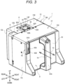
FIG. 3 is a perspective view of a printing device 1 (with a ribbon cartridge 9). -
FIG. 4 is a perspective view of theribbon cartridge 9. -
FIG. 5 is a perspective view of the printing device 1 (without theribbon cartridge 9 and with a cover 16). -
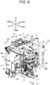
FIG. 6 is a perspective view of the printing device 1 (without ahousing 11 and with the cover 16). -
FIG. 7 is a perspective view of the printing device 1 (without asecond housing 13 and the cover 16). -
FIG. 8 is a cross-sectional view taken along a line VIII-VIII inFIG. 6 as viewed in a direction of arrows (without afirst housing 12 and with the second housing 13). -
FIG. 9 is a cross-sectional view taken along a line IX-IX inFIG. 6 as viewed in a direction of arrows (without thefirst housing 12 and with the second housing 13). -
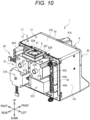
FIG. 10 is a perspective view of the printing device 1 (without thesecond housing 13, acontrol board 41, and a cover 6). -
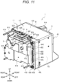
FIG. 11 is a perspective view of the printing device 1 (without thesecond housing 13 and thecontrol board 41, and with the cover 6). -
FIG. 12 is a perspective view of the printing device 1 (without thesecond housing 13, and with thecontrol board 41 and the cover 6). -
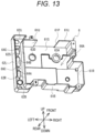
FIG. 13 is a cross-sectional view of thecover 6. - An embodiment of the present invention will be described with reference to the drawings. A
printing system 50 is a system for performing thermal transfer printing. Theprinting system 50 performs printing on a printing medium conveyed by an external device that is not shown. A specific example of the external device is a packaging machine that conveys a packaging material. In this case, for example, theprinting system 50 is used by being incorporated in a part of a conveyance line along which the printing medium is conveyed by the packaging machine. As shown inFIGs. 1 and2 , theprinting system 50 includes aprinting device 1 and amoving mechanism 5. - Hereinafter, in order to facilitate understanding of the description of the drawings, an upper side, a lower side, a left side, a right side, a front side, and a rear side of each configuration included in the
printing system 50 are defined. An upper side, a lower side, a left side, a right side, a front side, and a rear side of each of theprinting device 1, themoving mechanism 5, and aribbon cartridge 9, which will be described later, correspond to an upper side, a lower side, an obliquely upper left side, an obliquely lower right side, an obliquely lower left side, and an obliquely upper right side inFIG. 1 , respectively. InFIG. 1 , a conveyance direction of the printing medium coincides with a left-right direction. The printing medium is conveyed from a right side to a left side below theprinting device 1 by the external device (arrow Y1 (seeFIGs. 1 and2 )). - As shown in
FIGs. 1 to 3 , theprinting device 1 has a substantially rectangular parallelepiped shape. The ribbon cartridge 9 (seeFIG. 4 ), which will be described later, is detachably mounted on theprinting device 1. Theprinting device 1 feeds out anink ribbon 9A (seeFIG. 4 ) from aribbon roll 90A (seeFIG. 4 ) of the mountedribbon cartridge 9, and heats theink ribbon 9A by athermal head 7A (seeFIG. 5 and the like). Accordingly, the printing is performed on the printing medium conveyed below theprinting device 1. - As shown in
FIGs. 1 and2 , themoving mechanism 5 includes a pair offrame bodies 51, aguide rail 52, and aholding portion 56. The pair offrame bodies 51 are separated from each other in a front-rear direction. Eachframe body 51 includes anupper support portion 51A, alower support portion 51B, and a pair ofbridge portions 51C. Each of theupper support portion 51A and thelower support portion 51B has a prismatic shape and extends in the left-right direction. Theupper support portion 51A and thelower support portion 51B are separated from each other in an up-down direction. Theupper support portion 51A is disposed above thelower support portion 51B. The pair ofbridge portions 51C each have a columnar shape and extend in the up-down direction. The pair ofbridge portions 51C are bridged between both end portions of theupper support portion 51A and both end portions of thelower support portion 51B in the left-right direction. - The
guide rail 52 includes four columnar bodies extending in the front-rear direction. Hereinafter, the respective columnar bodies are referred to asguide rails upper support portions 51A of the pair offrame bodies 51. Theguide rail 52A is located on a left side with respect to theguide rail 52B. The guide rails 52C and 52D are bridged between thelower support portions 51B of the pair offrame bodies 51. Theguide rail 52C is located on a left side with respect to theguide rail 52D. - The holding
portion 56 includes adevice holding portion 56A and aplaten holding portion 56B. Each of thedevice holding portion 56A and theplaten holding portion 56B has a rectangular parallelepiped shape. Each of thedevice holding portion 56A and theplaten holding portion 56B has two through holes penetrating in the front-rear direction. The guide rails 52A and 52B are inserted through the respective two through holes of thedevice holding portion 56A. Thedevice holding portion 56A is supported to be movable in the front-rear direction with respect to theguide rails platen holding portion 56B. Theplaten holding portion 56B is supported to be movable in the front-rear direction with respect to theguide rails - The
device holding portion 56A has four throughholes 57 penetrating in the up-down direction. Abolt 57A is inserted through each throughhole 57 downward. The fourbolts 57A connect theprinting device 1 to thedevice holding portion 56A. Acutout portion 58 is provided at a rear end portion of thedevice holding portion 56A. Thecutout portion 58 is formed in a central portion of a lower surface of thedevice holding portion 56A in a left-right direction. On the other hand, theplaten holding portion 56B includes an upper surface having a flat plate shape, and holds the platen facing thethermal head 7A of theprinting device 1 in a case where printing is performed. Theplaten holding portion 56B is not connected to theprinting device 1, and theprinting device 1 and the platen are held independently in the up-down direction with a predetermined gap between theprinting device 1 and the platen. Theprinting device 1 is held by theguide rails device holding portion 56A. Theprinting device 1 moves in the front-rear direction (arrow Y2) as thedevice holding portion 56A moves in the front-rear direction with respect to theguide rails guide rails platen holding portion 56B. The platen moves in the front-rear direction as theplaten holding portion 56B moves in the front-rear direction with respect to theguide rails - As shown in
FIGs. 3 and4 , theribbon cartridge 9 includes abase portion 91 andshafts 92A to 92E (seeFIG. 4 , hereinafter, collectively referred to as a "shaft 92"). Thebase portion 91 has a substantially square plate shape. Acutout 910 is formed in an upper left corner portion of thebase portion 91. As shown inFIG. 3 , ahandle 91A extending in the up-down direction is provided on a front surface of thebase portion 91 and at a center of thebase portion 91 in the left-right direction. As shown inFIG. 4 , theshafts 92A to 92E each extend rearward from a rear surface of thebase portion 91. Theshafts 92A to 92D each have a columnar shape and are spindles rotatable about a rotation shaft extending in the front-rear direction. Theshaft 92E has a columnar shape and is fixed to thebase portion 91. - The
shaft 92A is provided on an upper side, with respect to a center of thebase portion 91, in the up-down direction and on a right side, with respect to the center of thebase portion 91, in the left-right direction. Theshaft 92D is provided on the upper side, with respect to the center of thebase portion 91, in the up-down direction and on a left side, with respect to the center of thebase portion 91, in the left-right direction. Theshafts spool 921 to which one end side of theink ribbon 9A is connected is mounted on theshaft 92A. Aspool 922 to which an other end side of theink ribbon 9A is connected is mounted on theshaft 92D. Theink ribbon 9A is wound in a roll shape around each of thespool 921 mounted on theshaft 92A and thespool 922 mounted on theshaft 92D. Hereinafter, theink ribbon 9A wound around thespool 921 in a roll shape is referred to as the "ribbon roll 90A". Theink ribbon 9A wound around thespool 922 in a roll shape is referred to as a "ribbon roll 90B". As thespools ink ribbon 9A is fed out from theribbon roll 90A and wound around theribbon roll 90B. - The
shaft 92B is provided on a lower right corner of thebase portion 91. Ahole 923 is formed in a tip end of theshaft 92B. Theshaft 92C is provided on a lower left corner of thebase portion 91. Anengaging gear 924 is provided on a tip end of theshaft 92C. Theink ribbon 9A stretched between thespools shafts shaft 92E is provided on an upper end portion of thebase portion 91 and at the center of thebase portion 91 in the left-right direction. - The
ribbon cartridge 9 is attachable to and detachable from theprinting device 1. For example, as shown inFIG. 3 , a user grips thehandle 91A of theribbon cartridge 9 and slides theribbon cartridge 9 forward with respect to the printing device 1 (arrow Y3). Accordingly, theribbon cartridge 9 is detached from theprinting device 1. On the other hand, for example, the user grips thehandle 91A of theribbon cartridge 9 and slides theribbon cartridge 9 rearward with respect to the printing device 1 (arrow Y4). Accordingly, theribbon cartridge 9 is mounted on theprinting device 1. - As shown in
FIG. 3 , theprinting device 1 includes ahousing 11. Thehousing 11 includes afirst housing 12 and asecond housing 13. Thefirst housing 12 covers an area, on a front side with respect to a base plate 21 (seeFIG. 5 ) that will be described later, of theprinting device 1. This area accommodates a mounting portion 22 (seeFIG. 5 ), thethermal head 7A (seeFIG. 5 ), a movingmechanism 7B (seeFIG. 5 ), a relay board 42 (seeFIG. 6 ), and the like, which will be described later. Thesecond housing 13 covers an area, on a rear side with respect to thebase plate 21, of theprinting device 1. This area accommodates a motor 31 (seeFIG. 10 ), a cover 6 (seeFIG. 11 ), a control board 41 (seeFIG. 12 ), and the like, which will be described later. - As shown in
FIGs. 3 and5 , thefirst housing 12 includespartial housings partial housing 12U is orthogonal to the up-down direction and extends in the left-right direction. Thepartial housing 12L is orthogonal to the left-right direction and extends downward from a left end portion of thepartial housing 12U. Thepartial housing 12B is orthogonal to the up-down direction and extends rightward from a lower end portion of thepartial housing 12L. Thepartial housing 12R is orthogonal to the left-right direction and extends downward from a right end portion of thepartial housing 12U. Thepartial housing 12C is orthogonal to the up-down direction and extends leftward from a lower end portion of thepartial housing 12R. As shown inFIG. 5 , rear end portions of thepartial housings base plate 21, which will be described later. - Front end portions of the
partial housings opening 12P. The ribbon cartridge 9 (seeFIG. 4 ) is mounted on theprinting device 1 by being inserted inside thefirst housing 12 through theopening 12P of thefirst housing 12. A shape of the base portion 91 (seeFIG. 4 ) of theribbon cartridge 9 is substantially the same as a shape of theopening 12P. Hereinafter, an area inside thefirst housing 12 where theribbon cartridge 9 mounted on theprinting device 1 is disposed is referred to as a mountingarea 90. A right end portion of thepartial housing 12B and a left end portion of thepartial housing 12C form an opening 12Q. Thethermal head 7A, which will be described later, heats theink ribbon 9A (seeFIG. 4 ) of the mountedribbon cartridge 9 to perform printing in a state of protruding downward from the opening 12Q. - As shown in
FIGs. 2 ,3 , and5 , thesecond housing 13 includespartial housings 13U (seeFIG. 3 ), 13L (seeFIG. 3 ), 13R (seeFIG. 5 ),13B (seeFIG. 5 ), and ? (seeFIG. 2 ) each having a plate shape. As shown inFIG. 2 , thepartial housing 13S has a square shape and is orthogonal to the front-rear direction. As shown inFIGs. 3 and5 , thepartial housing 13U is orthogonal to the up-down direction and extends forward from an upper end portion of thepartial housing 13S. Thepartial housing 13L is orthogonal to the left-right direction and extends forward from a left end portion of thepartial housing 13S. Thepartial housing 13L is located on a right side with respect to thepartial housing 12L of thefirst housing 12. Thepartial housing 13R is orthogonal to the left-right direction and extends forward from a right end portion of thepartial housing 13S. Thepartial housing 13B is orthogonal to the up-down direction and extends forward from a lower end portion of thepartial housing 13S. - Front end portions of the
partial housings base plate 21, which will be described later. As shown inFIG. 3 , anopening 13P is formed substantially at a center of thepartial housing 13U in the left-right direction. Afan 81, which will be described later, is exposed from theopening 13P. Anopening 13Q is formed in a front end portion of thepartial housing 13L. A part of thecover 6, which will be described later, is exposed to the outside through theopening 13Q from the inside of thesecond housing 13. - As shown in
FIGs. 5 to 7 , thebase plate 21 of theprinting device 1 has a substantially square plate shape. Thebase plate 21 is orthogonal to the front-rear direction. Thebase plate 21 includes the mounting portion 22 (22A to 22E), thethermal head 7A, the movingmechanism 7B, and the like. - The mounting
portion 22 is provided on a front surface of thebase plate 21. In a case where the ribbon cartridge 9 (seeFIG. 4 ) is mounted on theprinting device 1, theshafts 92A to 92E (seeFIG. 4 ) of theribbon cartridge 9 are connected to the mountingportions 22A to 22E, respectively. The mountingportion 22A is provided on an upper side, with respect to a center of thebase plate 21, in the up-down direction and on a right side, with respect to a center of thebase plate 21, in the left-right direction. The mountingportion 22D is provided on the upper side, with respect to the center of thebase plate 21, in the up-down direction and on a left side, with respect to the center of thebase plate 21, in the left-right direction. The mountingportions ribbon cartridge 9 is mounted on theprinting device 1, theribbon roll 90A wound around the spool 921 (seeFIG. 4 ) connected to theshaft 92A is mounted on the mountingportion 22A. Theribbon roll 90B (seeFIG. 4 ) wound around thespool 922 connected to theshaft 92D is mounted on the mountingportion 22D. - The mounting
portion 22B is provided on a lower right corner of thebase plate 21. The mountingportion 22B has a columnar shape and extends forward from thebase plate 21. The mountingportion 22C is provided on a lower left corner of thebase plate 21. The mountingportion 22C has a cylindrical shape and includes an engaging gear that is not shown inside the mountingportion 22C. The mountingportion 22E is provided on an upper end portion of thebase plate 21 and at the center of thebase plate 21 in the left-right direction. The mountingportion 22E has a tubular shape and extends forward from thebase plate 21. In a case where theribbon cartridge 9 is mounted on theprinting device 1, the mountingportion 22B is inserted through the hole 923 (seeFIG. 4 ) of theshaft 92B. The engaging gear of the mountingportion 22C is engaged with the engaging gear 924 (seeFIG. 4 ) of theshaft 92C. Theshaft 92E is inserted through a tubular interior of the mountingportion 22E. - A rotation shaft of a
motor 31A (seeFIG. 9 ), which will be described later, is connected to the mountingportion 22A from behind. The mountingportion 22A rotates in accordance with rotation of themotor 31A. A rotation shaft of amotor 31B (seeFIG. 9 ), which will be described later, is connected to the mountingportion 22D. The mountingportion 22D rotates in accordance with rotation of themotor 31B. In a case where the mountingportions shafts 92A to 92E (seeFIG. 4 ) of theribbon cartridge 9 are connected to the mountingportions 22A to 22E, respectively, theink ribbon 9A (seeFIG. 4 ) of theribbon cartridge 9 is guided in a state of coming into contact with theshafts spools 921 and 922 (seeFIG. 4 ) to be conveyed in theprinting device 1. - As shown in
FIGs. 5 to 7 , thethermal head 7A is provided on a lower end portion of the front surface of thebase plate 21 and at a portion between the mountingportions thermal head 7A is supported to be movable in the up-down direction and the left-right direction with respect to thebase plate 21. Thethermal head 7A is a line thermal head. Thethermal head 7A includes abase portion 71, arail 72, and a plurality ofheating elements 71A. Thethermal head 7A is connected to abelt 32A connected to apulley 32 connected to the rotation shaft of themotor 31B (seeFIG. 10 ), which will be described later. Thethermal head 7A moves in the left-right direction as thebelt 32A is rotated by themotor 31B. - The
base portion 71 has an elongated plate shape and extends in the front-rear direction. Thebase portion 71 is inclined with respect to a direction orthogonal to the up-down direction. Thebase portion 71 is biased upward by aspring 71B (seeFIG. 6 ). Therail 72 extending in the front-rear direction is provided on an upper side of thebase portion 71. - The plurality of
heating elements 71A arranged in the front-rear direction are provided on a lower side of thebase portion 71. The plurality ofheating elements 71A come into contact, from above, with a portion of theink ribbon 9A (seeFIG. 4 ) fed out from theribbon roll 90A of theribbon cartridge 9 in accordance with the rotation of the mountingportions shafts FIG. 2 ). The plurality ofheating elements 71A sandwich theink ribbon 9A and the printing medium between the plurality ofheating elements 71A and the platen held on the upper surface of theplaten holding portion 56B. The plurality ofheating elements 71A heat theink ribbon 9A while pressing theink ribbon 9A against the printing medium. Accordingly, thethermal head 7A transfers an ink of theink ribbon 9A to the printing medium to perform the printing. - The moving
mechanism 7B is provided on the front surface of thebase plate 21 and above thethermal head 7A. The movingmechanism 7B is a mechanism for moving thethermal head 7A in the up-down direction and the left-right direction. The movingmechanism 7B includes a pair ofsupport portions 75,guide rails member 77. The pair ofsupport portions 75 are provided above the mountingportions support portions 75 are supported by thebase plate 21 to be swingable about a rotation shaft extending in the left-right direction. The guide rails 76A, 76B, and 76C each have a columnar shape and extend in the left-right direction. The guide rails 76A, 76B, and 76C are bridged between the pair ofsupport portions 75. - As shown in
FIGs. 5 ,7 , and8 , anarm 33 is connected to theguide rail 76B. Thearm 33 extends rearward from theguide rail 76B, passes through anopening 21A formed in thebase plate 21, and extends to the rear of thebase plate 21. Theopening 21A allows the front and the rear of thebase plate 21 to communicate with each other. Afilter 210 for preventing passage of dust and dirt is provided in theopening 21A. Thefilter 210 is flexible and does not interfere with movement of thearm 33. As shown inFIG. 8 , a rear end portion of thearm 33 is connected to a crank 34 connected to a rotation shaft of amotor 31C, which will be described later. Thearm 33 is driven as thecrank 34 is rotated by themotor 31C. The pair ofsupport portions 75 and theguide rails arm 33 is driven. - As shown in
FIGs. 5 to 8 , the swingingmember 77 is supported to be movable in the left-right direction with respect to theguide rail 76C. As shown inFIGs. 6 and8 , the swingingmember 77 includes afirst portion 77A extending obliquely downward and forward from theguide rail 76C, and asecond portion 77B extending obliquely upward and forward from theguide rail 76C. Apulley 77C is rotatably supported at a tip end of thefirst portion 77A. Thepulley 77C comes into contact with therail 72 of thethermal head 7A from above. Thepulley 77C moves the swingingmember 77 in the left-right direction in accordance with the movement of thethermal head 7A in the left-right direction. Arotational body 77D is rotatably supported at a tip end of thesecond portion 77B. Therotational body 77D comes into contact with theguide rail 76A from the front. - In a case where the
motor 31C rotates, the swingingmember 77 swings in conjunction with swinging of the pair ofsupport portions 75 and theguide rails FIG. 8 , in a case where the swingingmember 77 swings in a counterclockwise direction as viewed from a right side, thefirst portion 77A of the swingingmember 77 pushes thethermal head 7A downward via thepulley 77C. Thethermal head 7A moves downward against a biasing force of thespring 71B. In a state where thethermal head 7A moves to a lowest position, the plurality ofheating elements 71A of thethermal head 7A slightly protrude downward from the opening 12Q (seeFIG. 5 ) of thehousing 11. On the other hand, in a case where the swingingmember 77 swings in a clockwise direction as viewed from the right side, thethermal head 7A moves upward in accordance with the biasing force of thespring 71B. In a state where thethermal head 7A moves to an uppermost position, the plurality ofheating elements 71A of thethermal head 7A are located above the opening 12Q of thehousing 11. - As shown in
FIG. 6 , therelay board 42 is provided on a left side of thebase plate 21. Therelay board 42 extends in a direction orthogonal to thebase plate 21, that is, in a direction orthogonal to the left-right direction. Therelay board 42 is a printed circuit board on which various devices are mounted. Hereinafter, for ease of description, therelay board 42 may be described as being divided into afirst portion 42A and asecond portion 42B. Thefirst portion 42A is a portion on an upper side, with respect to a center of therelay board 42, in the up-down direction. Thesecond portion 42B is a portion on a lower side, with respect to the center of therelay board 42, in the up-down direction. - The
first portion 42A has a rectangular shape elongated in the front-rear direction. As shown inFIGs. 7 and9 , positions of front end portions of thefirst portion 42A and thepartial housing 12L of thefirst housing 12 in the front-rear direction coincide with each other. As shown inFIG. 9 , a rear end portion of thefirst portion 42A is located behind thebase plate 21. That is, thefirst portion 42A extends from a front end portion of thefirst housing 12 to a position behind thebase plate 21. A portion of thefirst portion 42A disposed on a front side with respect to thebase plate 21 is located on a left side of the mountingarea 90 where theribbon cartridge 9 is to be mounted. - As shown in
FIG. 7 , aninterface portion 43 is provided on the front end portion of thefirst portion 42A. Theinterface portion 43 includes aUSB connector 43A and apush button 43B on a front surface of theinterface portion 43. A USB memory that is not shown is connected to theUSB connector 43A. Thepush button 43B is operated in a case where an instruction to theprinting device 1 is input. Thefirst portion 42A transmits, to the control board 41 (seeFIG. 12 ) that will be described later, an electric signal received from the USB memory connected to theUSB connector 43A and an electric signal indicating that thepush button 43B is operated. Theinterface portion 43 is provided with a plurality of indicators formed of LEDs, and an operation state of theprinting device 1, a remaining amount of the ribbon, and the like can be indicated to the user by colors and lighting patterns of the indicators. As shown inFIG. 3 , theinterface portion 43 is adjacent to thecutout 910 of thebase portion 91 in a state where the ribbon cartridge 9 (seeFIG. 4 ) is mounted. Therefore, the front surface of theinterface portion 43 is not covered by thebase portion 91 even in a case where theribbon cartridge 9 is mounted. - As shown in
FIG. 6 , thesecond portion 42B extends downward from a lower end portion of thefirst portion 42A and a center of thefirst portion 42A in the front-rear direction. A front end portion of thesecond portion 42B is located behind the front end portion of thefirst portion 42A. A rear end portion of thesecond portion 42B is located behind the base plate 21 (seeFIG. 9 ). As shown inFIG. 7 , anencoder 74A is provided on a right surface of thesecond portion 42B. Theencoder 74A measures a rotation amount of the pair ofsupport portions 75 of the movingmechanism 7B. A CPU mounted on thecontrol board 41, which will be described later, can detect a movement amount of thethermal head 7A in the up-down direction, based on the rotation amount detected by theencoder 74A. Further, anLED 74B is provided on the right surface of thesecond portion 42B. TheLED 74B irradiates the area on the front side with respect to thebase plate 21 with light. Due to the irradiation with the light, the vicinity of the mountingportion 22 becomes bright. Accordingly, the user can visually recognize a remaining amount of theink ribbon 9A of theribbon cartridge 9 and an operation state of theprinting device 1 through a window that is not shown provided in thebase portion 91. By turning on theLED 74B at the time of attaching/detaching theribbon cartridge 9, it is also possible to help an attachment/detachment operation of theribbon cartridge 9. - As shown in
FIGs. 5 and6 , a portion of therelay board 42 located on the front side than thebase plate 21 is covered with acover 16 except for a left surface of therelay board 42. As shown inFIG. 5 , a part of therelay board 42 is accommodated in a space between thepartial housing 12L of thefirst housing 12 and thecover 16. A part of thecover 16 is transmissive and allows the light from theLED 74B to transmit through the part of thecover 16. - As shown in
FIGs. 10 to 12 , a portion of therelay board 42 located on the rear side with respect to thebase plate 21 is covered with thecover 6, which will be described later. As shown inFIG. 9 , a rear end portion of therelay board 42 is located on a front side than a rear end portion of thesecond housing 13. As shown inFIG. 10 ,connectors relay board 42. - As shown in
FIG. 10 ,motors 31A to 31D (hereinafter, collectively referred to as the "motor 31") are provided on a rear surface of thebase plate 21. As shown inFIG. 9 , themotor 31A is connected to a portion of the rear surface of thebase plate 21 that is a rear side with respect to the mountingportion 22A (seeFIGs. 5 to 7 ) on the front surface of thebase plate 21. Themotor 31D is connected to a portion of the rear surface of thebase plate 21 that is a rear side with respect to the mountingportion 22D (seeFIGs. 5 to 7 ) on the front surface of thebase plate 21. Themotors motor 31A is disposed on a right side with respect to themotor 31D. Rotation shafts of themotors base plate 21 from the rear surface toward the front surface, and are connected to the mountingportions motor 31A rotates the mountingportion 22A, and themotor 31D rotates the mountingportion 22D. Aheat insulator 30A is provided between themotor 31A and thebase plate 21. Aheat insulator 30D is provided between themotor 31D and thebase plate 21. Theheat insulators motors base plate 21, respectively. - As shown in
FIG. 10 , themotor 31B is connected to a lower side of the rear surface of thebase plate 21 with respect to themotor 31A. Themotor 31C is connected to a lower side, with respect to themotor 31D, of the rear surface of thebase plate 21. As shown inFIG. 7 , the rotation shaft of themotor 31B penetrates thebase plate 21 from the rear surface toward the front surface, and is connected to thepulley 32 on the front side with respect to thebase plate 21. Themotor 31B rotates thepulley 32 to move thethermal head 7A in the left-right direction. As shown inFIG. 8 , the rotation shaft of themotor 31C extends rightward and is connected to thecrank 34. Themotor 31C rotates thecrank 34 to move thethermal head 7A in the up-down direction. - As shown in
FIG. 12 , thecontrol board 41 is disposed behind the motor 31 (seeFIG. 10 ). Thecontrol board 41 is a printed circuit board on which various devices are mounted. Thecontrol board 41 is fixed, by spacers 41A, to a position separated rearward from thebase plate 21. Thecontrol board 41 is orthogonal to the front-rear direction and parallel to thebase plate 21. The CPU for controlling themotor 31, encoders for detecting rotation amounts of therespective motors control board 41. The encoder for detecting the rotation amount of themotor 31A is provided on a front surface of thecontrol board 41 and behind arotation shaft 33A (seeFIGs. 10 and11 ) of themotor 31A. The encoder for detecting the rotation amount of themotor 31D is provided on the front surface of thecontrol board 41 and behind arotation shaft 33D (seeFIGs. 10 and11 ) of themotor 31D. Thecontrol board 41 is electrically connected to therelay board 42 by an FPC that is not shown. - As shown in
FIG. 11 , thecover 6 is disposed behind thebase plate 21 and forward of the control board 41 (seeFIG. 12 ). Thecover 6 covers, from behind, themotors 31A to 31D and a part of the rear end portion of therelay board 42. - As shown in
FIGs. 11 and13 , thecover 6 includespartial covers partial cover 61S has irregularities, and a main component of thepartial cover 61S is orthogonal to the front-rear direction. Thepartial cover 61S is disposed between themotor 31 and thecontrol board 41. The partial covers 61U, 61R, 61L, and 61B extend forward from an upper end portion, a right end portion, a left end portion, and a lower end portion of thepartial cover 61S, respectively. Thepartial cover 62S extends leftward from a front end portion of thepartial cover 61L and is orthogonal to the front-rear direction. The partial covers 62U, 62B, and 62L extend forward from an upper end portion, a lower end portion, and a left end portion of thepartial cover 62S, respectively. Thepartial cover 62S is provided with apartition wall 62R extending forward from a front surface of thepartial cover 62S. Thepartition wall 62R is orthogonal to the left-right direction and extends in the up-down direction. Rear end portions of thepartial covers partition wall 62R are connected to thebase plate 21. - The
cover 6 partitions the area covered by the second housing 13 (seeFIGs. 2 and3 , and the like) into afirst area 66A, asecond area 66B, and athird area 66C. Thefirst area 66A is an area surrounded by thepartial covers partition wall 62R. Themotors 31A to 31D are disposed in thefirst area 66A. Thethird area 66C is an area surrounded by thepartial covers partition wall 62R. A part of the rear end portion of therelay board 42 is disposed in thethird area 66C. As shown inFIG. 9 , thesecond area 66B is an area other than thefirst area 66A and thethird area 66C in the area covered by the second housing 13 (seeFIGs. 2 and3 , and the like). Thecontrol board 41 is disposed in thesecond area 66B. The first area 661 and thesecond area 66B are arranged in the front-rear direction. - As shown in
FIG. 13 , anopening 61P is provided in thepartial cover 61U. Throughholes partial cover 61S. As shown inFIG. 11 , therotation shaft 33A of themotor 31A is inserted through the throughhole 63A from the front and protrudes rearward. Therotation shaft 33D of themotor 31D is inserted through the throughhole 63D from the front and protrudes rearward. As shown inFIG. 13 , throughholes partial cover 62S. As shown inFIGs. 11 and12 , theconnectors relay board 42 are inserted through the throughholes connector 45C provided on therelay board 42 is exposed from the throughhole 64C. - As shown in
FIG. 3 , afan unit 8 is disposed in theopening 13P of thepartial housing 13U corresponding to an upper end portion of thesecond housing 13. As shown inFIG. 6 , thefan unit 8 is fixed to the upper end portion of thebase plate 21 and at the center of thebase plate 21 in the left-right direction, and protrudes rearward. As shown inFIG. 11 , thefan unit 8 is located above theopening 61P provided in thepartial cover 61U of thecover 6. Thefan unit 8 includes thefan 81 and a fixingportion 82. - The
fan 81 includes a plurality of propellers and a hub to which the plurality of propellers are connected, and rotates about a rotation shaft extending in the up-down direction. A motor is built in thefan 81. In a case where thefan 81 rotates, air in thefirst area 66A of thecover 6 is discharged to the outside of theprinting device 1 through theopening 61P of thecover 6 and theopening 13P (seeFIG. 9 ) of thesecond housing 13. - The fixing
portion 82 has a C-shape when viewed from above, and covers a left side, a right side, and a rear side of thefan 81. The fixingportion 82 rotatably supports thefan 81 and fixes thefan 81 to thebase plate 21. The fixingportion 82 includes arectangular plate body 82P on an upper surface of the fixingportion 82. A front end portion of theplate body 82P is fixed to an upper side of the upper end portion of thebase plate 21. Screw holes 82A extending in the up-down direction are formed at respective four corners of thebase plate 21. Afilter 85 for preventing passage of dust and dirt is provided in an opening inside theplate body 82P. - As shown in
FIG. 2 , the fourbolts 57A inserted through the four throughholes 57 of thedevice holding portion 56A are screwed into the respective fourscrew holes 82A of the fixingportion 82 shown inFIG. 3 . Theprinting device 1 is held by thedevice holding portion 56A by connecting thedevice holding portion 56A to the fixingportion 82 with the fourbolts 57A. Thedevice holding portion 56A covers thefan 81 from above in a state of being connected to the fixingportion 82. - The
ribbon cartridge 9 is mounted on theprinting device 1. In a state where theprinting device 1 is held by the movingmechanism 5 with the holdingportion 56, a printing surface of the printing medium conveyed by the external device and thethermal head 7A of theprinting device 1 face each other in the up-down direction. Further, a platen roller that is not shown is disposed on a side opposite to theprinting device 1 with respect to the printing medium. - The
fan unit 8 is powered on, and thefan 81 starts to rotate. As shown inFIG. 8 , thefan 81 discharges, to the outside, the air in thefirst area 66A of thecover 6 from an upper end portion of the housing 11 (arrow Y13). The discharged air passes through a gap formed between thefan unit 8 and thecutout portion 58 of thedevice holding portion 56A connected to the fixingportion 82 of thefan unit 8. Accordingly, an upward air flow is formed inside thefirst area 66A (arrow Y12). In accordance with the air flow, air outside thehousing 11 is taken into an area inside thehousing 11 and on the front side of thebase plate 21 through the opening 12Q (seeFIG. 5 ) in the lower end portion of the housing 11 (arrow Y10). Further, the air taken into the area on the front side of thebase plate 21 passes through theopening 21A of thebase plate 21 to the rear side and flows into thefirst area 66A (arrow Y11). - In a case where a printing action by the
printing device 1 is started, the mountingportions motors shafts 92A and 92F of theribbon cartridge 9 connected to the respective mountingportions ink ribbon 9A is fed out from theribbon roll 90A of thespool 921 mounted on theshaft 92A, and is wound around theribbon roll 90B of thespool 922 mounted on theshaft 92D. A portion of theink ribbon 9A between theshafts - The
motors fan 81 of thefan unit 8, the air flow (arrow Y12) is generated inside thefirst area 66A. The air flow cools themotors - In a case where a conveyance speed of the
ink ribbon 9A is increased to a predetermined speed, themotor 31C is driven, and thethermal head 7A is lowered to protrude below the opening 12Q. Thethermal head 7A comes into contact with the platen roller from above via theink ribbon 9A and the printing medium. Theink ribbon 9A is pressed against the printing surface of the printing medium in accordance with the movement of thethermal head 7A. Theheating elements 71A of thethermal head 7A generate heat, and the ink of theink ribbon 9A is transferred to the printing surface of the printing medium. As described above, printing by theprinting device 1 is performed. - Various operations on the
thermal head 7A of the printing device 1 (for example, replacement and cleaning of thethermal head 7A) may be performed. In this case, the printing medium and the platen roller are arranged below theprinting device 1, and thus usually, an operator often accesses thethermal head 7A from above theprinting device 1 to perform various operations. Here, in theprinting device 1, therelay board 42 is disposed on the left side of thebase plate 21, and therelay board 42 is not disposed above thethermal head 7A. Therefore, theprinting device 1 can prevent therelay board 42 from becoming an obstacle in a case where the operator accesses thethermal head 7A from above to perform various operations. Therefore, theprinting device 1 can facilitate various operations performed on thethermal head 7A by the operator. - The
relay board 42 extends from the front end portion of thefirst housing 12 to the rear side with respect to thebase plate 21. Therefore, theprinting device 1 can use therelay board 42 as a transmission path of an electric signal transmitted from the front end portion of thefirst housing 12 to thecontrol board 41 behind thebase plate 21. In this case, it is not necessary to use a signal line or the like for transmitting an electric signal, and thus it is possible to reduce the cost of theprinting device 1. - The rear end portion of the
relay board 42 is located on the front side than the rear end portion of thesecond housing 13. Therefore, in theprinting device 1, a connector on a cable side connected to theconnectors relay board 42 can be disposed in a portion between the rear end portion of thesecond housing 13 and the rear end portion of therelay board 42. In this case, it is possible to reduce a rearward protrusion, from the rear end portion of thesecond housing 13, of the connector on the cable side. Therefore, theprinting device 1 can reduce a space in the front-rear direction required at the time of printing. - The
printing device 1 includes thecover 16 that covers therelay board 42. In this case, thecover 16 can reduce dust, dirt, and the like adhering to therelay board 42. - The
printing device 1 can use therelay board 42 as a transmission path for transmitting an electric signal received from a USB cable connected to theUSB connector 43A of theinterface portion 43. Therelay board 42 is disposed on the left side with respect to the mountingarea 90 of theribbon cartridge 9, and thus therelay board 42 does not interfere with the attachment/detachment action of theribbon cartridge 9 with respect to theprinting device 1. Therefore, in a case where theribbon cartridge 9 is attached to or detached from theprinting device 1, it is not necessary to remove the USB cable from theUSB connector 43A. Therefore, in theprinting device 1, theribbon cartridge 9 can be easily attached to and detached from theprinting device 1 in a state where the USB cable is connected to theUSB connector 43A. - The
encoder 74A provided on the right surface of thesecond portion 42B of therelay board 42 can detect the movement amount of thethermal head 7A in the up-down direction. Theprinting device 1 can easily hold theencoder 74A with therelay board 42. TheLED 74B provided on the right surface of thesecond portion 42B of therelay board 42 can irradiate the front side of thebase plate 21 with light. Theprinting device 1 can easily hold theLED 74B with therelay board 42. - The present invention is not limited to the above embodiment, and various modifications are possible. The
relay board 42 may be provided on a right side of thebase plate 21, or may be provided on both left and right sides of thebase plate 21. Therelay board 42 may include only thefirst portion 42A, and may not include thesecond portion 42B. Conversely, therelay board 42 may include only thesecond portion 42B, and may not include thefirst portion 42A. A front end portion of therelay board 42 may be located behind the front end portion of thefirst housing 12. Positions of the rear end portion of therelay board 42 and the rear end portion of thesecond housing 13 in the front-rear direction may coincide with each other. In this case, the connector on the cable side connected to theconnectors relay board 42 may protrude rearward than the rear end portion of thesecond housing 13. - The
cover 16 covering a part of therelay board 42 may further cover a left side of therelay board 42. Thecover 16 may be integrated with thefirst housing 12. Thecover 16 may not be provided. Theinterface portion 43 may be provided on a left surface of therelay board 42. - Various sensors that measures driving amounts of various drive mechanisms connected to the
base plate 21 may be mounted on therelay board 42. For example, an optical sensor that measures a ribbon amount of the ribbon rolls 90A and 90B, a contact sensor that detects whether theribbon cartridge 9 is mounted, and the like may be mounted on therelay board 42. The number ofLEDs 74B mounted on therelay board 42 is not limited to one, and may be plural. Theencoder 74A and theLED 74B may not be mounted on therelay board 42. - The front-rear direction is an example of a "first direction" in the present invention. The front side is an example of "one side in the first direction" in the present invention. The rear side is an example of "the other side in the first direction" in the present invention. The up-down direction is an example of a "second direction" in the present invention. The lower side is an example of "one side in the second direction" in the present invention. The left-right direction is an example of a "third direction" in the present invention. The left side is an example of "one side in the third direction" in the present invention. The
relay board 42 is an example of a "printed circuit board" in the present invention. -
- 1 :
- printing device
- 7A :
- thermal head
- 8 :
- fan unit
- 11 :
- housing
- 12 :
- first housing
- 13 :
- second housing
- 16 :
- cover
- 21 :
- base plate
- 22 :
- mounting portion
- 30 :
- motor
- 41 :
- control board
- 42 :
- relay board
- 43 :
- interface portion
- 43A :
- USB connector
- 43B :
- push button
- 71A :
- heating element
- 74A :
- encoder
- 74B
- LED
- 90 :
- mounting area
Claims (7)
- A printing device comprising:a base plate orthogonal to a first direction;a mounting portion provided rotatably on a surface, which is at one side in the first direction, of the base plate, wherein a ribbon roll having an ink ribbon wound is to be mounted on the mounting portion;a thermal head provided on a surface, which is at the one side in the first direction, of the base plate, and configured to perform printing on a printing medium disposed on one side in a second direction orthogonal to the first direction; anda printed circuit board located on one side, with respect to the base plate, in a third direction orthogonal to the first direction and the second direction, and extending in a direction intersecting the base plate.
- The printing device according to claim 1, further comprising:a first housing covering one side, in the first direction, of the base plate, the thermal head, and the printed circuit board,wherein the printed circuit board extends from an end portion, which is at the one side in the first direction, of the first housing to an other side in the first direction than the base plate.
- The printing device according to claim 1 or 2, further comprising:a second housing covering an other side, in the first direction, of the base plate,wherein an end portion, which is at the other side in the first direction, of the printed circuit board is located on the one side in the first direction than an end portion, which is at an other side in the first direction, of the second housing.
- The printing device according to any one of claims 1 to 3, further comprising:
a cover covering the printed circuit board. - The printing device according to claim 2,wherein the printed circuit board is a relay board configured to relay an electric signal,the printed circuit board includes, a connector to which an external interface is to be connected, the connector provided on an end portion, which is at the one side in the first direction, of the printed circuit board, andthe printed circuit board is located on one side in the third direction with respect to a mounting area where the ribbon roll mounted on the mounting portion is to be disposed.
- The printing device according to any one of claims 1 to 5,
wherein a sensor is mounted on the printed circuit board, the sensor being configured to measure a driving amount of a drive portion provided on the one side, in the first direction, of the base plate. - The printing device according to any one of claims 1 to 6,
wherein an LED is mounted on the printed circuit board, the LED being configured to irradiate the one side, in the first direction, of the base plate with light.
Applications Claiming Priority (2)
| Application Number | Priority Date | Filing Date | Title |
|---|---|---|---|
| JP2020131086A JP7435346B2 (en) | 2020-07-31 | 2020-07-31 | printing device |
| PCT/JP2021/012877 WO2022024458A1 (en) | 2020-07-31 | 2021-03-26 | Printing device |
Publications (3)
| Publication Number | Publication Date |
|---|---|
| EP4190575A1 true EP4190575A1 (en) | 2023-06-07 |
| EP4190575A4 EP4190575A4 (en) | 2024-06-26 |
| EP4190575B1 EP4190575B1 (en) | 2025-10-22 |
Family
ID=80037876
Family Applications (1)
| Application Number | Title | Priority Date | Filing Date |
|---|---|---|---|
| EP21850643.4A Active EP4190575B1 (en) | 2020-07-31 | 2021-03-26 | Printing device |
Country Status (4)
| Country | Link |
|---|---|
| US (1) | US12330429B2 (en) |
| EP (1) | EP4190575B1 (en) |
| JP (1) | JP7435346B2 (en) |
| WO (1) | WO2022024458A1 (en) |
Family Cites Families (8)
| Publication number | Priority date | Publication date | Assignee | Title |
|---|---|---|---|---|
| US5657066A (en) * | 1992-10-02 | 1997-08-12 | Zebra Technologies Corporation | Thermal demand printer |
| US5447379A (en) * | 1994-10-31 | 1995-09-05 | Monarch Marking Systems, Inc. | Portable tag or label printer |
| US7042478B2 (en) * | 1999-03-26 | 2006-05-09 | Datamax Corporation | Modular printer |
| KR20070072735A (en) * | 2006-01-02 | 2007-07-05 | 삼성전자주식회사 | Sublimation Image Forming Device |
| JP2010253905A (en) * | 2009-04-28 | 2010-11-11 | Edm Kk | Thermal printer |
| JP6986220B2 (en) * | 2017-05-31 | 2021-12-22 | ブラザー工業株式会社 | Printing device and printing device body |
| JP2019077111A (en) | 2017-10-25 | 2019-05-23 | ブラザー工業株式会社 | Printing system |
| JP6950451B2 (en) * | 2017-10-25 | 2021-10-13 | ブラザー工業株式会社 | Printing equipment |
-
2020
- 2020-07-31 JP JP2020131086A patent/JP7435346B2/en active Active
-
2021
- 2021-03-26 EP EP21850643.4A patent/EP4190575B1/en active Active
- 2021-03-26 WO PCT/JP2021/012877 patent/WO2022024458A1/en not_active Ceased
-
2023
- 2023-01-31 US US18/162,354 patent/US12330429B2/en active Active
Also Published As
| Publication number | Publication date |
|---|---|
| US20230173824A1 (en) | 2023-06-08 |
| EP4190575B1 (en) | 2025-10-22 |
| WO2022024458A1 (en) | 2022-02-03 |
| JP2022027212A (en) | 2022-02-10 |
| EP4190575A4 (en) | 2024-06-26 |
| JP7435346B2 (en) | 2024-02-21 |
| US12330429B2 (en) | 2025-06-17 |
Similar Documents
| Publication | Publication Date | Title |
|---|---|---|
| EP1916117B1 (en) | Printer unit | |
| EP1559563B1 (en) | Portable electronic apparatus | |
| JP2010008724A (en) | Tandem-type process unit and image forming apparatus | |
| CN112743995B (en) | Printing unit and printer | |
| EP3130471A1 (en) | Printer | |
| CN114450170B (en) | Printing device and printing box | |
| JP2016190377A (en) | Printing device | |
| CN114502386B (en) | Printing tape box | |
| EP4190575B1 (en) | Printing device | |
| CN114585516B (en) | Printing apparatus | |
| JPWO2019065653A1 (en) | Printer | |
| JP2022027214A (en) | Printing equipment | |
| CN116872620B (en) | Printing device | |
| CN116802060A (en) | Auxiliary tape cassette, printing tape cassette and printing cassette | |
| US20230202781A1 (en) | Sheet conveying apparatus, image recording apparatus and roll body replacing method | |
| JP6981829B2 (en) | Printer | |
| CN114514123B (en) | Printing equipment | |
| CN210666360U (en) | Developing box | |
| JP2020184681A (en) | Printing equipment | |
| JP3732825B2 (en) | Ribbon guide unit, ink ribbon cartridge, and image forming apparatus | |
| US20250289246A1 (en) | Printer and cutting unit | |
| US12629949B2 (en) | Printing device having restricting part on cover for restricting displacement of mounted tape cassette due to thrust load, and tape cassette therefor | |
| EP4190574B1 (en) | Printing device | |
| JP2979429B2 (en) | Line thermal printer | |
| JP6982153B2 (en) | Printer |
Legal Events
| Date | Code | Title | Description |
|---|---|---|---|
| STAA | Information on the status of an ep patent application or granted ep patent |
Free format text: STATUS: THE INTERNATIONAL PUBLICATION HAS BEEN MADE |
|
| PUAI | Public reference made under article 153(3) epc to a published international application that has entered the european phase |
Free format text: ORIGINAL CODE: 0009012 |
|
| STAA | Information on the status of an ep patent application or granted ep patent |
Free format text: STATUS: REQUEST FOR EXAMINATION WAS MADE |
|
| 17P | Request for examination filed |
Effective date: 20230127 |
|
| AK | Designated contracting states |
Kind code of ref document: A1 Designated state(s): AL AT BE BG CH CY CZ DE DK EE ES FI FR GB GR HR HU IE IS IT LI LT LU LV MC MK MT NL NO PL PT RO RS SE SI SK SM TR |
|
| P01 | Opt-out of the competence of the unified patent court (upc) registered |
Effective date: 20230620 |
|
| DAV | Request for validation of the european patent (deleted) | ||
| DAX | Request for extension of the european patent (deleted) | ||
| A4 | Supplementary search report drawn up and despatched |
Effective date: 20240528 |
|
| RIC1 | Information provided on ipc code assigned before grant |
Ipc: B41J 29/38 20060101ALI20240522BHEP Ipc: B41J 2/325 20060101AFI20240522BHEP |
|
| GRAP | Despatch of communication of intention to grant a patent |
Free format text: ORIGINAL CODE: EPIDOSNIGR1 |
|
| STAA | Information on the status of an ep patent application or granted ep patent |
Free format text: STATUS: GRANT OF PATENT IS INTENDED |
|
| INTG | Intention to grant announced |
Effective date: 20250707 |
|
| GRAS | Grant fee paid |
Free format text: ORIGINAL CODE: EPIDOSNIGR3 |
|
| GRAA | (expected) grant |
Free format text: ORIGINAL CODE: 0009210 |
|
| STAA | Information on the status of an ep patent application or granted ep patent |
Free format text: STATUS: THE PATENT HAS BEEN GRANTED |
|
| AK | Designated contracting states |
Kind code of ref document: B1 Designated state(s): AL AT BE BG CH CY CZ DE DK EE ES FI FR GB GR HR HU IE IS IT LI LT LU LV MC MK MT NL NO PL PT RO RS SE SI SK SM TR |
|
| REG | Reference to a national code |
Ref country code: CH Ref legal event code: F10 Free format text: ST27 STATUS EVENT CODE: U-0-0-F10-F00 (AS PROVIDED BY THE NATIONAL OFFICE) Effective date: 20251022 Ref country code: GB Ref legal event code: FG4D |
|
| REG | Reference to a national code |
Ref country code: DE Ref legal event code: R096 Ref document number: 602021040974 Country of ref document: DE |
|
| REG | Reference to a national code |
Ref country code: IE Ref legal event code: FG4D |
|
| REG | Reference to a national code |
Ref country code: NL Ref legal event code: MP Effective date: 20251022 |
|
| PG25 | Lapsed in a contracting state [announced via postgrant information from national office to epo] |
Ref country code: NL Free format text: LAPSE BECAUSE OF FAILURE TO SUBMIT A TRANSLATION OF THE DESCRIPTION OR TO PAY THE FEE WITHIN THE PRESCRIBED TIME-LIMIT Effective date: 20251022 |
|
| PGFP | Annual fee paid to national office [announced via postgrant information from national office to epo] |
Ref country code: GB Payment date: 20260312 Year of fee payment: 6 |
|
| PG25 | Lapsed in a contracting state [announced via postgrant information from national office to epo] |
Ref country code: ES Free format text: LAPSE BECAUSE OF FAILURE TO SUBMIT A TRANSLATION OF THE DESCRIPTION OR TO PAY THE FEE WITHIN THE PRESCRIBED TIME-LIMIT Effective date: 20251022 |
|
| REG | Reference to a national code |
Ref country code: LT Ref legal event code: MG9D |
|
| PG25 | Lapsed in a contracting state [announced via postgrant information from national office to epo] |
Ref country code: NO Free format text: LAPSE BECAUSE OF FAILURE TO SUBMIT A TRANSLATION OF THE DESCRIPTION OR TO PAY THE FEE WITHIN THE PRESCRIBED TIME-LIMIT Effective date: 20260122 |
|
| PGFP | Annual fee paid to national office [announced via postgrant information from national office to epo] |
Ref country code: DE Payment date: 20260305 Year of fee payment: 6 |
|
| PG25 | Lapsed in a contracting state [announced via postgrant information from national office to epo] |
Ref country code: FI Free format text: LAPSE BECAUSE OF FAILURE TO SUBMIT A TRANSLATION OF THE DESCRIPTION OR TO PAY THE FEE WITHIN THE PRESCRIBED TIME-LIMIT Effective date: 20251022 Ref country code: HR Free format text: LAPSE BECAUSE OF FAILURE TO SUBMIT A TRANSLATION OF THE DESCRIPTION OR TO PAY THE FEE WITHIN THE PRESCRIBED TIME-LIMIT Effective date: 20251022 Ref country code: AT Free format text: LAPSE BECAUSE OF FAILURE TO SUBMIT A TRANSLATION OF THE DESCRIPTION OR TO PAY THE FEE WITHIN THE PRESCRIBED TIME-LIMIT Effective date: 20251022 |
|
| REG | Reference to a national code |
Ref country code: AT Ref legal event code: MK05 Ref document number: 1848841 Country of ref document: AT Kind code of ref document: T Effective date: 20251022 |
|
| PG25 | Lapsed in a contracting state [announced via postgrant information from national office to epo] |
Ref country code: RS Free format text: LAPSE BECAUSE OF FAILURE TO SUBMIT A TRANSLATION OF THE DESCRIPTION OR TO PAY THE FEE WITHIN THE PRESCRIBED TIME-LIMIT Effective date: 20260122 |
|
| PG25 | Lapsed in a contracting state [announced via postgrant information from national office to epo] |
Ref country code: IS Free format text: LAPSE BECAUSE OF FAILURE TO SUBMIT A TRANSLATION OF THE DESCRIPTION OR TO PAY THE FEE WITHIN THE PRESCRIBED TIME-LIMIT Effective date: 20260222 |
|
| PGFP | Annual fee paid to national office [announced via postgrant information from national office to epo] |
Ref country code: FR Payment date: 20260309 Year of fee payment: 6 |
|
| PG25 | Lapsed in a contracting state [announced via postgrant information from national office to epo] |
Ref country code: PT Free format text: LAPSE BECAUSE OF FAILURE TO SUBMIT A TRANSLATION OF THE DESCRIPTION OR TO PAY THE FEE WITHIN THE PRESCRIBED TIME-LIMIT Effective date: 20260223 |
|
| PG25 | Lapsed in a contracting state [announced via postgrant information from national office to epo] |
Ref country code: PL Free format text: LAPSE BECAUSE OF FAILURE TO SUBMIT A TRANSLATION OF THE DESCRIPTION OR TO PAY THE FEE WITHIN THE PRESCRIBED TIME-LIMIT Effective date: 20251022 |
|
| PG25 | Lapsed in a contracting state [announced via postgrant information from national office to epo] |
Ref country code: LV Free format text: LAPSE BECAUSE OF FAILURE TO SUBMIT A TRANSLATION OF THE DESCRIPTION OR TO PAY THE FEE WITHIN THE PRESCRIBED TIME-LIMIT Effective date: 20251022 |
|
| PG25 | Lapsed in a contracting state [announced via postgrant information from national office to epo] |
Ref country code: BG Free format text: LAPSE BECAUSE OF FAILURE TO SUBMIT A TRANSLATION OF THE DESCRIPTION OR TO PAY THE FEE WITHIN THE PRESCRIBED TIME-LIMIT Effective date: 20251022 |
|
| PG25 | Lapsed in a contracting state [announced via postgrant information from national office to epo] |
Ref country code: LT Free format text: LAPSE BECAUSE OF FAILURE TO SUBMIT A TRANSLATION OF THE DESCRIPTION OR TO PAY THE FEE WITHIN THE PRESCRIBED TIME-LIMIT Effective date: 20251022 |
|
| PG25 | Lapsed in a contracting state [announced via postgrant information from national office to epo] |
Ref country code: SM Free format text: LAPSE BECAUSE OF FAILURE TO SUBMIT A TRANSLATION OF THE DESCRIPTION OR TO PAY THE FEE WITHIN THE PRESCRIBED TIME-LIMIT Effective date: 20251022 |
|
| PG25 | Lapsed in a contracting state [announced via postgrant information from national office to epo] |
Ref country code: DK Free format text: LAPSE BECAUSE OF FAILURE TO SUBMIT A TRANSLATION OF THE DESCRIPTION OR TO PAY THE FEE WITHIN THE PRESCRIBED TIME-LIMIT Effective date: 20251022 |
|
| PG25 | Lapsed in a contracting state [announced via postgrant information from national office to epo] |
Ref country code: IT Free format text: LAPSE BECAUSE OF FAILURE TO SUBMIT A TRANSLATION OF THE DESCRIPTION OR TO PAY THE FEE WITHIN THE PRESCRIBED TIME-LIMIT Effective date: 20251022 |
|
| PG25 | Lapsed in a contracting state [announced via postgrant information from national office to epo] |
Ref country code: EE Free format text: LAPSE BECAUSE OF FAILURE TO SUBMIT A TRANSLATION OF THE DESCRIPTION OR TO PAY THE FEE WITHIN THE PRESCRIBED TIME-LIMIT Effective date: 20251022 |
|
| PG25 | Lapsed in a contracting state [announced via postgrant information from national office to epo] |
Ref country code: CZ Free format text: LAPSE BECAUSE OF FAILURE TO SUBMIT A TRANSLATION OF THE DESCRIPTION OR TO PAY THE FEE WITHIN THE PRESCRIBED TIME-LIMIT Effective date: 20251022 |
|
| PG25 | Lapsed in a contracting state [announced via postgrant information from national office to epo] |
Ref country code: SK Free format text: LAPSE BECAUSE OF FAILURE TO SUBMIT A TRANSLATION OF THE DESCRIPTION OR TO PAY THE FEE WITHIN THE PRESCRIBED TIME-LIMIT Effective date: 20251022 |
|
| PG25 | Lapsed in a contracting state [announced via postgrant information from national office to epo] |
Ref country code: SE Free format text: LAPSE BECAUSE OF FAILURE TO SUBMIT A TRANSLATION OF THE DESCRIPTION OR TO PAY THE FEE WITHIN THE PRESCRIBED TIME-LIMIT Effective date: 20251022 |