EP4189381B1 - Verfahren zur dynamischen kontrolle mittels ultraschallbildgebung - Google Patents
Verfahren zur dynamischen kontrolle mittels ultraschallbildgebung Download PDFInfo
- Publication number
- EP4189381B1 EP4189381B1 EP21799078.7A EP21799078A EP4189381B1 EP 4189381 B1 EP4189381 B1 EP 4189381B1 EP 21799078 A EP21799078 A EP 21799078A EP 4189381 B1 EP4189381 B1 EP 4189381B1
- Authority
- EP
- European Patent Office
- Prior art keywords
- tested
- sensor
- ultrasonic
- tube
- movement
- Prior art date
- Legal status (The legal status is an assumption and is not a legal conclusion. Google has not performed a legal analysis and makes no representation as to the accuracy of the status listed.)
- Active
Links
Images


Classifications
-
- G—PHYSICS
- G01—MEASURING; TESTING
- G01N—INVESTIGATING OR ANALYSING MATERIALS BY DETERMINING THEIR CHEMICAL OR PHYSICAL PROPERTIES
- G01N29/00—Investigating or analysing materials by the use of ultrasonic, sonic or infrasonic waves; Visualisation of the interior of objects by transmitting ultrasonic or sonic waves through the object
- G01N29/22—Details, e.g. general constructional or apparatus details
- G01N29/26—Arrangements for orientation or scanning by relative movement of the head and the sensor
- G01N29/262—Arrangements for orientation or scanning by relative movement of the head and the sensor by electronic orientation or focusing, e.g. with phased arrays
-
- G—PHYSICS
- G01—MEASURING; TESTING
- G01N—INVESTIGATING OR ANALYSING MATERIALS BY DETERMINING THEIR CHEMICAL OR PHYSICAL PROPERTIES
- G01N29/00—Investigating or analysing materials by the use of ultrasonic, sonic or infrasonic waves; Visualisation of the interior of objects by transmitting ultrasonic or sonic waves through the object
- G01N29/04—Analysing solids
- G01N29/043—Analysing solids in the interior, e.g. by shear waves
-
- G—PHYSICS
- G01—MEASURING; TESTING
- G01N—INVESTIGATING OR ANALYSING MATERIALS BY DETERMINING THEIR CHEMICAL OR PHYSICAL PROPERTIES
- G01N29/00—Investigating or analysing materials by the use of ultrasonic, sonic or infrasonic waves; Visualisation of the interior of objects by transmitting ultrasonic or sonic waves through the object
- G01N29/04—Analysing solids
- G01N29/06—Visualisation of the interior, e.g. acoustic microscopy
- G01N29/0609—Display arrangements, e.g. colour displays
- G01N29/0645—Display representation or displayed parameters, e.g. A-, B- or C-Scan
-
- G—PHYSICS
- G01—MEASURING; TESTING
- G01N—INVESTIGATING OR ANALYSING MATERIALS BY DETERMINING THEIR CHEMICAL OR PHYSICAL PROPERTIES
- G01N29/00—Investigating or analysing materials by the use of ultrasonic, sonic or infrasonic waves; Visualisation of the interior of objects by transmitting ultrasonic or sonic waves through the object
- G01N29/04—Analysing solids
- G01N29/06—Visualisation of the interior, e.g. acoustic microscopy
- G01N29/0654—Imaging
- G01N29/069—Defect imaging, localisation and sizing using, e.g. time of flight diffraction [TOFD], synthetic aperture focusing technique [SAFT], Amplituden-Laufzeit-Ortskurven [ALOK] technique
-
- G—PHYSICS
- G01—MEASURING; TESTING
- G01N—INVESTIGATING OR ANALYSING MATERIALS BY DETERMINING THEIR CHEMICAL OR PHYSICAL PROPERTIES
- G01N29/00—Investigating or analysing materials by the use of ultrasonic, sonic or infrasonic waves; Visualisation of the interior of objects by transmitting ultrasonic or sonic waves through the object
- G01N29/22—Details, e.g. general constructional or apparatus details
- G01N29/26—Arrangements for orientation or scanning by relative movement of the head and the sensor
- G01N29/265—Arrangements for orientation or scanning by relative movement of the head and the sensor by moving the sensor relative to a stationary material
-
- G—PHYSICS
- G01—MEASURING; TESTING
- G01N—INVESTIGATING OR ANALYSING MATERIALS BY DETERMINING THEIR CHEMICAL OR PHYSICAL PROPERTIES
- G01N29/00—Investigating or analysing materials by the use of ultrasonic, sonic or infrasonic waves; Visualisation of the interior of objects by transmitting ultrasonic or sonic waves through the object
- G01N29/22—Details, e.g. general constructional or apparatus details
- G01N29/26—Arrangements for orientation or scanning by relative movement of the head and the sensor
- G01N29/27—Arrangements for orientation or scanning by relative movement of the head and the sensor by moving the material relative to a stationary sensor
-
- G—PHYSICS
- G01—MEASURING; TESTING
- G01N—INVESTIGATING OR ANALYSING MATERIALS BY DETERMINING THEIR CHEMICAL OR PHYSICAL PROPERTIES
- G01N29/00—Investigating or analysing materials by the use of ultrasonic, sonic or infrasonic waves; Visualisation of the interior of objects by transmitting ultrasonic or sonic waves through the object
- G01N29/22—Details, e.g. general constructional or apparatus details
- G01N29/32—Arrangements for suppressing undesired influences, e.g. temperature or pressure variations, compensating for signal noise
-
- G—PHYSICS
- G01—MEASURING; TESTING
- G01N—INVESTIGATING OR ANALYSING MATERIALS BY DETERMINING THEIR CHEMICAL OR PHYSICAL PROPERTIES
- G01N29/00—Investigating or analysing materials by the use of ultrasonic, sonic or infrasonic waves; Visualisation of the interior of objects by transmitting ultrasonic or sonic waves through the object
- G01N29/44—Processing the detected response signal, e.g. electronic circuits specially adapted therefor
- G01N29/4463—Signal correction, e.g. distance amplitude correction [DAC], distance gain size [DGS], noise filtering
-
- G—PHYSICS
- G01—MEASURING; TESTING
- G01N—INVESTIGATING OR ANALYSING MATERIALS BY DETERMINING THEIR CHEMICAL OR PHYSICAL PROPERTIES
- G01N2291/00—Indexing codes associated with group G01N29/00
- G01N2291/10—Number of transducers
- G01N2291/106—Number of transducers one or more transducer arrays
-
- G—PHYSICS
- G01—MEASURING; TESTING
- G01N—INVESTIGATING OR ANALYSING MATERIALS BY DETERMINING THEIR CHEMICAL OR PHYSICAL PROPERTIES
- G01N2291/00—Indexing codes associated with group G01N29/00
- G01N2291/26—Scanned objects
- G01N2291/263—Surfaces
- G01N2291/2634—Surfaces cylindrical from outside
Definitions
- the invention relates to the field of non-destructive testing such as non-destructive conformity testing of metal products.
- the invention relates more particularly to ultrasonic testing of the presence of defects within a tubular metal product.
- Metal tubes are widely used in various fields of the energy industry such as power generation, oil and gas, and mechanical engineering. Like most metallurgical products, tubes are susceptible to manufacturing defects, such as material inclusions in the steel, cracks on their internal or external surface, or porosities. Generally, any heterogeneity in the steel matrix is seen as an imperfection that is likely to adversely affect the mechanical strength of the tube in service.
- the tubes are therefore checked after their manufacture, not only to detect any defects, but also, where appropriate, to determine information useful for assessing the dangerousness of these defects, in particular their size, depth, position, nature or orientation, and the satisfaction of these tubes with standards.
- Ultrasonic waves are propagated in the tube and, among the waves reflected by the tube, those which cannot be attributed to the geometry of the tube are searched for. Defects such as inclusions or absences of material constitute variations within the wave propagation medium, and therefore generate the reflection of part of the energy of the ultrasonic waves when they are struck by these ultrasonic waves.
- phased array transducer One type of sensor used for ultrasonic wave monitoring is a multi-element, sequentially controlled type, generally called a "phased array transducer".
- This type of sensor comprises a plurality of electroacoustic elements, generally in the form of piezoelectric elements. These piezoelectric elements may be distributed over an active face. of the sensor surrounding the tube to be controlled or according to a main alignment direction so as to form a "bar”.
- FMC Full Matrix Capture
- a processing circuit records the individual response, subsequently called A-scan, of the n elements of the sensor for each of the n emissions. For each element, this individual response represents the amplitude of the ultrasonic waves received by said element during a given listening duration.
- This method allows to obtain precise images of the tube but requires a significant acquisition time. There is therefore a need for a method allowing to obtain a precise image of a part to be controlled quickly and reliably.
- US-5299576 discloses a method for controlling a moving object by ultrasonic imaging, comprising a step of acquiring data by a multi-element sensor, a step of generating data representative of the object as a function of the waves reflected by the object, a step of calculating a corrective displacement as a function of the relative displacement between the sensor and the object, and a step of correcting said representative data as a function of said corrective displacement.
- US-10156549 describes a method of ultrasonic testing of an object such as a human body or a metal pipe, comprising driving a multi-element sensor in motion along the surface of the object, acquiring data by the sensor, and generating data representative of the object based on waves reflected by the object; a coupling wedge separates the tested object from the sensor.
- An idea underlying the invention is to obtain data representative of a part to be controlled, for example TFM images or A-Scans of a tube, quickly and reliably.
- an idea underlying the invention is to obtain data representative of the part to be controlled during a relative movement between the sensor enabling this data to be obtained and the part to be controlled.
- an idea underlying the invention is to obtain this data during a continuous relative movement between the sensor and the part to be controlled.
- An idea underlying the invention is to take into account the relative movement between the sensor and the part to be controlled for the generation reliable and precise representative data of the element to be controlled.
- the invention provides a method for dynamically acquiring data representative of a part to be controlled, as defined in claim 1 .
- Data representative of a part to be checked is understood to mean information relating to the shape, thickness, differences in environments, etc. of the part to be checked.
- these data representative of the part to be checked comprise a plurality of A-Scans of the part to be checked.
- the duration relative to the reference time corresponds to the time difference between the acquisition time of data representative of the part to be checked and the reference time, this duration being positive or negative depending on whether said acquisition time is before or after the reference time.
- such a dynamic acquisition method may comprise one or more of the following features.
- the relative movement between the sensor and the part to be controlled is continuous. Such continuous movement during data acquisition allows good speed of execution of the method.
- the part to be tested may take many forms.
- the part to be tested is a tube.
- Such a tube may have many cross-sectional shapes, such as circular, square or other.
- such a tube may be of constant or variable thickness.
- the application of a correction to the data representative of the part to be checked comprises a step of applying a virtual displacement, for example a virtual rotation around an axis of rotation of the part to be checked, to said data representative of the part to be checked so as to generate corrected data.
- Virtual displacement is understood to mean the modification of the data representative of the profile of the part to be checked to simulate a corrective displacement of the part to be checked without said part to be checked physically performing such a corrective displacement.
- the calculation of the corrective displacement comprises the calculation of a respective corrective displacement for one or more of the data representative of the part to be checked.
- the duration relative to the reference time for a respective corrective displacement corresponds to the duration per relative to the reference time corresponding to the time differential between the time corresponding to the relative position between the sensor and the part to be checked represented by said data representative of the part to be checked and the reference time, this duration being positive or negative depending on whether said time represented by the data representative of the part to be checked to be corrected is before or after the reference time.
- the application of the correction is carried out for one, several or each data representative of the part to be checked according to the respective corrective displacement associated with said data representative of the part to be checked.
- Two ultrasonic shots and preferably all the ultrasonic shots, are carried out sequentially, that is to say at distinct emission times, so as to avoid interference between ultrasonic waves emitted from distinct emitting elements.
- the corrective displacement can be calculated for different portions of a relative displacement between the sensor and the part to be tested.
- the corrective displacement is calculated as a function of the relative displacement between the sensor and the part to be tested between the emission of two distinct ultrasonic shots, for example two successive ultrasonic shots.
- the reference position is the relative position between the sensor and the part to be tested at a reference time corresponding to the emission of an ultrasonic shot.
- each ultrasonic shot makes it possible to obtain a set of data relating to the part to be checked according to an identified path of the ultrasonic wave, said path starting from the position of the emitting element and generating reflected waves received at the respective positions of the receiving elements receiving said reflected waves.
- the step of generating the corrected data comprises a selection of a reference position.
- the reference position corresponds to a relative position between the part to be checked and the sensor during a selected ultrasonic shot.
- the reference position, and therefore the corresponding reference time is provided beforehand for example by being selected by default, for example by being recorded in a storage memory of the system implementing the method.
- the reference position is the relative position between the sensor and the part to be checked at the time of the first shot.
- the reference position is the relative position between the sensor and the part to be checked at the time of the last ultrasonic shot emitted.
- the data representative of the part to be tested comprise an intensity of the ultrasonic waves reflected by the part to be tested and received by each receiving element of the sensor over time.
- Data representative of the part to be tested in this form are hereinafter called A-Scans.
- the data representative of the part to be tested comprise the A-Scans generated from the ultrasonic waves received by each of the receiving elements of the sensor following the same ultrasonic signal emitted by an emitting element of the sensor.
- the data representative of the part to be inspected comprise the A-Scans generated from the ultrasonic waves received by one, several or each of the receiving elements of the sensor following a plurality of ultrasonic shots emitted successively by a corresponding emitting element of the sensor, and preferably a plurality of respective ultrasonic shots emitted successively by several distinct emitting elements of the sensor.
- the data representative of the part to be inspected comprise a matrix comprising the A-Scans generated from a plurality of successive ultrasonic shots and the ultrasonic waves reflected by the part to be tested following said ultrasonic shots and received by a plurality of receiving elements.
- the data representative of the part to be checked comprises a partial image for one, several or each ultrasonic shots of the plurality of ultrasonic shots emitted during the acquisition step, the application of a correction to the data representative of the part to be checked comprising a step of modifying the partial image to simulate a movement of the part to be checked from the relative position between the sensor and the part to be checked illustrated on said partial image to the reference position in order to generate a corrected partial image.
- a partial image is generated based on the waves reflected by the part to be tested that result from the same ultrasonic shot.
- each point of a partial image is determined based on the A-Scans generated from the waves reflected by the part to be tested that are received by the receiving elements following the emission of the same ultrasonic signal.
- the method comprises generating a representative image of the part to be checked based on the corrected data.
- the method further comprises a step of generating a representative image of the part to be checked by superimposing a plurality of corrected partial images.
- Such partial images and corrected partial images make it possible to obtain a representative image of the part to be tested and thus information on the part to be tested quickly and clearly, for example on the location, dimensions and other characteristics of a defect present in the part to be tested.
- the listening duration has a start time equal to the time of emission of the ultrasonic shot, said listening duration being greater than or equal to a maximum flight time between the emission of the ultrasonic shot and the reception by a said receiver element of the sensor of a wave reflected by a face of the part to be tested opposite the sensor so that the corrective displacement is calculated as a function of the relative displacement between the sensor and the part to be tested during a propagation time between a time of emission of an ultrasonic shot and a time of reception of the waves reflected by the part to be tested resulting from said ultrasonic shot by the receiver element(s).
- the final reception time corresponds to the listening duration, i.e.
- the corrective displacement is calculated as a function of the relative displacement between the sensor and the part to be checked during the propagation of the same ultrasonic shot from its emission to the reception of the waves reflected by the part to be checked resulting from this ultrasonic shot by the receiving element(s).
- the data representative of the part to be checked comprise, for each receiving element, a respective A-Scan representative of an intensity of the waves received by said receiver as a function of a listening time of said receiving element.
- the calculation of the corrective displacement comprises the calculation of a signal reception duration by a said receiving element of the plurality of receiving elements as a function of the relative displacement between the sensor and the part to be checked.
- each time block of a said A-Scan has a duration equal to the signal reception duration of the receiving element for the relative displacement of the sensor with respect to the part to be checked.
- the duration of signal reception by a said receiving element corresponds to the duration during which, during the relative movement between the sensor and the part to be controlled, a signal emitted continuously from the part to be controlled is received by said receiving element, a duration greater than this reception duration resulting in the reception of said continuous signal by an adjacent receiving element.
- one, several or each time block has a duration equal to a signal reception duration from the receiver having received the waves reflected by the part to be checked having made it possible to generate said A-Scan.
- the calculation of the corrective displacement comprises the calculation of an offset in number of receiving elements as a function of the relative positions of the receiving elements, the signal reception durations of said receiving elements and the time of emission of the ultrasonic signal.
- the offset is an integer representing, for a given time block of an original A-Scan, the number of A-Scans by which said time block must be offset according to the direction of relative movement between the part to be tested and the sensor.
- the offset represents the number of A-Scans between the original A-Scan and a target A-Scan to which said time block must be assigned for the same time range.
- the offset is equal to the maximum number of successive receiving elements following, according to a direction of relative movement between the sensor and the part to be checked and from the receiving element having received the reflected waves of said original A-Scan, that is to say according to a reference position and the direction of rotation of the part, the cumulative sum of the signal reception durations of which is less than the duration elapsed between the reference time and the start time of said time block.
- the application of a correction comprises, for at least one time block of the original A-Scan, the replacement of a portion of a target A-Scan by said time block, said target A-Scan corresponding to the A-Scan generated from the nth receiving element following the receiver having received the parts of the energy of the reflected waves of the original A-Scan, in the direction of relative movement between the sensor and the part to be checked, n being the calculated offset, the portion of the target A-Scan having the same start and end time as the time block.
- the relative movement between the sensor and the part to be checked results from a movement of the part to be checked and from maintaining the sensor in a fixed position during the movement of the part to be checked, the movement of the part to be checked having an angular component around an axis of rotation, the calculation of a corrective movement comprising a step of calculating the angular movement of the part to be checked during said relative movement between the sensor and the part to be checked.
- the calculation of a corrective movement comprises a step of calculating the angular movement of the part to be checked during said relative movement between the sensor and the part to be checked and in which the correction of the data representative of the part to be checked comprises the simulation of a rotation of the part to be checked around its axis of rotation according to an angle corresponding to the angular movement of the part to be checked during the acquisition step.
- the relative movement between the sensor and the part to be controlled may be of different natures.
- the relative movement between the sensor and the part to be tested results from a movement of the part to be tested and from the sensor being held in a fixed position during the movement of the part to be tested.
- the movement of the part to be tested has an angular component about an axis of rotation, for example the longitudinal axis of a tube in the case of a part to be tested in the form of a tube.
- the movement of the part to be tested has a longitudinal component along a longitudinal axis, for example the longitudinal axis of the tube being tested.
- the part to be tested is, for example, driven in a helical movement relative to the sensor.
- the relative movement between the sensor and the part to be tested results from the movement of the sensor and from the part to be tested being held in a fixed position.
- the calculation of a corrective displacement comprises a step of calculating the angular displacement of the part to be checked.
- the calculation of the corrective displacement comprises a calculation of the relative displacement between the sensor and the part to be checked along an axis of relative displacement between the sensor and the part to be checked.
- the generation of the image representative of the part to be checked is carried out according to the corrected A-Scans.
- Oil, gas or other exploitation requires a large number of tubes. Due to the many constraints that these tubes undergo both during their installation and during their operation, these tubes meet standards in order to avoid any degradation and any leakage into the environment.
- Tubular elements manufactured for this type of operation must therefore be checked to ensure that they do not have any defects that could call into question their operation.
- representative data of the tube are generated using sensors, this data making it possible to detect the presence and characteristics of possible defects in the tube.
- Such defects are, for example, surface cracks or discontinuities in the material inside the tube wall.
- FIG. 1 schematically illustrates a cross-sectional view of a tube 1 and a sensor 2.
- the tube 1 is of circular cylindrical shape and has a longitudinal axis 3.
- the tube 1 has a defect 4.
- the defect 4 is for example a crack in the wall of the tube 1, that is to say that this defect 4 is located between an external surface 5 of the tube 1 and an internal surface 6 of said tube 1.
- the senor 2 comprises a plurality of elements 7.
- the sensor 2 comprises a housing 8 carrying all of the elements 7. These elements 7 are aligned along a longitudinal axis 9 of the sensor 2.
- Each element 7 is capable of, on the one hand, emitting an ultrasonic wave E, also called an ultrasonic shot E, and, on the other hand, receiving received waves R.
- an element 7 can be a piezoelectric strip having a width of 1 mm and a length, also called elevation, of 10 mm.
- the sensor 2 is positioned on the periphery, for example above, of the tube 1 so that the elements 7 are oriented to emit the ultrasonic wave E in the direction of the tube 1.
- the sensor 2 is positioned so as to present its longitudinal axis 9 perpendicular to the longitudinal axis 3 of the tube 1.
- a couplant separates the tube 1 from the surface of the sensor 2 to allow the propagation of the ultrasonic waves E, for example a column of water, gel or any other medium allowing the propagation of the ultrasonic wave.
- the signal representative of the ultrasonic waves received and/or the absence of ultrasonic waves received by each of the elements 7 is recorded. These recordings are made during a predetermined time range following the emission of an ultrasonic wave E. During this time range, the ultrasonic waves received by the element 7 comprise the waves resulting from the reflection of the ultrasonic wave on the tube 1.
- the elements 7 thus make it possible to generate, from all the waves received R, and therefore the waves reflected following an ultrasonic shot E, A-Scans representative of the tube 1.
- Each A-Scan represents the amplitude of the waves received R by an element 7 as a function of time, this amplitude being zero when the element 7 does not receive an ultrasonic wave.
- These A-Scans therefore make it possible to know the state of the tube 1 as a function of the position of the element emitting the ultrasonic wave E, of the element receiving the reflected waves, of the time of flight of the ultrasonic waves and of the propagation media.
- ultrasonic shots E are carried out successively with each of the elements 7 of the sensor 2.
- a plurality of A-scan type data is thus obtained comprising the ultrasonic waves reflected by the tube 1 and received by each of the elements 7 of the sensor 2.
- a sensor 2 comprising n elements 7, all the A-Scans generated from the successive ultrasonic shots E and the ultrasonic waves received R by the n elements 7 are recorded in a matrix as illustrated in the figure 2 , where the A-scan corresponding to the emission by element n and the reception by element m is recorded in the cell E n R m .
- the matrix acquisition strategy is of the TFM type, from the English acronym "total focusing method".
- the acquisition method is of the "sparse-TFM" type (which means that all the cells of the matrix do not contain an A-scan (emission and/or reception with a part of the elements), PWI (from the English "Plane Wave Imaging"), i.e. several or all of the elements are used in transmission for each ultrasonic shot, with different angles of incidence by means of a delay law allowing the ultrasonic beam to be deflected, sparse-PWI, or any other acquisition method consisting of recording A-scans associated with a multitude of ultrasonic trajectories traveled between one or more elements in transmission and one or more elements in reception.
- PWI from the English "Plane Wave Imaging”
- each line 10 represents all the A-Scans generated from the n elements 7 of the sensor 2 following the emission of an ultrasonic wave E i emitted by an i th element 7. These A-Scans are therefore representative of the waves received R 1 to R n by the n elements 7 following the emission of the ultrasonic wave E i .
- the first line 10 of the matrix illustrated in the figure 2 comprises a set of data E 1 R 1 , E 1 R 2 ... E 1 R n-1 , E 1 R n , corresponding to the A-Scans generated from the waves received R 1 , R 2 ... R n-1 and R n by the n elements 7 following the emission of the ultrasonic shot E 1 by the first element 7.
- the last line 10 of this matrix comprises a set of data E n R 1 , E n R 2 .... E n R n-1 and E n R n corresponding to the A-Scans generated from the waves received R 1 to R n by the n elements 7 following the emission of the ultrasonic shot E n by the n th element 7.
- each column 11 of this matrix contains all the A-Scans generated from the waves received R i by an i th element 7 following the n successive ultrasonic shots E 1 to E n by the n elements 7.
- the first column 11 of the matrix illustrated in the figure 2 comprises a set of data E 1 R 1 , E 2 R 1 ... E n R 1 corresponding to the A-Scans generated from the waves received R 1 by the first element 7 following the n ultrasonic shots E 1 to E n by the n elements 7.
- the matrix (also called the "FMC matrix”) illustrated in the figure 2 therefore comprises n rows and n columns, each row 10 corresponding to all the A-Scans generated following the emission of an ultrasonic shot E i by an i th element 7 of the sensor 2 and each column 11 corresponding to the A-Scans generated from the waves received R j by a j th element 7 of the sensor 2.
- each pixel of the image is associated with a value representative of the propagation medium of the tube 1.
- such an image comprises, for each point of the image, the sum of the values of the different A-Scans of the matrix as a function of the theoretical flight times at the level of said point of the image.
- all of the A-Scans of the matrix are analyzed and compiled to define the acoustic properties of the tube 1 at said point of the image.
- a theoretical flight time of the ultrasonic wave is associated which corresponds to the time required for the ultrasonic wave E leaving the emitting element to reach the targeted point of the image added to the time required for a wave reflected from said targeted point of the image to reach the receiving element corresponding to the A-Scan.
- the amplitude of the A-Scan signal at the theoretical flight time thus determined is representative of the material constituting the tube 1 for the targeted point. If the tube 1 does not have any defect or change in the nature of the medium at the targeted image point, the emitted ultrasonic wave E is not reflected at said targeted point so that there is no reflected wave and the A-Scan signal of the receiving element 7 has a zero amplitude, or equivalent to the background noise for example linked to the electronic system or other disturbances, at the theoretical flight time determined.
- the targeted image point corresponds to a defect or change in the medium in the tube 1
- the emitted ultrasonic wave E is reflected at said targeted image point so that the A-Scan signal of the receiving element 7 has a non-zero amplitude at the theoretical flight time, this non-zero amplitude being representative of the reflected wave at the targeted image point.
- the image obtained by adding for each pixel the amplitude of the different A-Scans as a function of the corresponding theoretical flight times therefore makes it possible to determine the nature of the medium in which the ultrasonic wave E circulated at each point of the image.
- tube 1 and sensor 2 are driven in relative motion during data acquisition. This relative movement between the tube 1 and the sensor 2, and therefore the elements 7, is preferably continuous.
- the acquisition of data representative of the tube 1 is carried out by maintaining the sensor 2, and therefore the elements 7, in a fixed position and by driving the tube 1 in movement according to a helical movement around its longitudinal axis 3.
- a relative movement between the tube 1 and the elements 7 is equivalent to a movement of the elements 7 on the one hand in translation along the longitudinal axis 3 of the tube 1 and, on the other hand, in rotation around said longitudinal axis 3 of the tube 1.
- Such a helical movement of the tube 1 is for example carried out at a rotation speed around the longitudinal axis 3 of the tube 1 of the order of 1 m/s.
- this relative movement between the tube 1 and the sensor 2 could also be obtained by maintaining the tube 1 in a fixed position and driving the sensor 2 in rotation around the tube 1 or by any other relative movement between the sensor 2 and the tube 1.
- the relative displacement between tube 1 and elements 7 implies a relative displacement of defect 4 relative to elements 7. This relative displacement results in an angular shift of the location of defect 4 around longitudinal axis 3 of tube 1 relative to elements 7. Between two successive ultrasonic shots E, the data recorded by elements 7 within the same matrix therefore exhibit an angular shift corresponding to the relative displacement between tube 1 and elements 7.
- FIG 3 illustrates such a displacement of the defect 4 by an angle ⁇ between two successive ultrasonic shots E i and E i+1 .
- This displacement of the defect 4 is linked to the rotation of the tube 1 in a direction of rotation 24 around the longitudinal axis 3.
- the same defect 4 is illustrated both in a first position 12 and in a second position 13 on the figure 3 thus illustrating the angle shift ⁇ in the positioning of defect 4 between two successive ultrasonic shots E i and E i+1 .
- the A-Scans resulting from the ultrasonic shot E i have an amplitude corresponding to the presence of the defect 4 in a first position 12 while the A-Scans resulting from the ultrasonic shot E i+1 have an amplitude corresponding to the presence of the defect 4 in a second position 13, this second position 13 being offset by the angle ⁇ relative to the first position 12. Consequently, the sum of the amplitudes of the different A-Scans for a targeted point of the image is no longer representative of the structure of the tube 1 since, for the same targeted point of the image, the amplitudes of the different A-Scans of the matrix do not correspond to the same position of the defect 4.
- the image thus obtained from the matrix is therefore blurred, the defect 4 being indicated imprecisely on the image, the defect 4 appearing in the form of a streak forming an arc of a circle instead of a well-defined spot.
- the blurring effect of the image is all the stronger as the rotation speed of the tube 1 around its longitudinal axis 3 is important. Indeed, the faster the tube 1 rotates around its longitudinal axis 3, the greater the angular offset ⁇ of the defect 4 between two ultrasonic shots E i and E i+1 and therefore the greater the angular offset of positioning of the defect 4 between these two successive ultrasonic shots E i and E i+1 .
- FIGS. 4 to 6 illustrate as an example three images generated in the context of a tube 1 and a sensor 2 similar to those above with regard to the Figures 1 to 3 with a helical displacement drive of the tube 1 at different speeds. These precise images are generated using a 10MHz sensor 2 comprising 64 elements 7 spaced 0.35 mm center to center.
- the reconstruction of the image according to the invention advantageously takes into account the relative movement between the tube 1 and the sensor 2 during the acquisition of the data. For this, the data representative of the tube 1 obtained during the relative movement between the tube 1 and the sensor 2 are corrected.
- This reference position is a relative position between sensor 2 and tube 1 during the movement of tube 1.
- This reference position can be predetermined or arbitrarily selected.
- This reference position can be any relative position between sensor 2 and tube 1 during the movement of tube 1, for example the relative position between tube 1 and sensor 2 at a reference time corresponding to the time of emission of the first ultrasonic shot E 1 or of the last ultrasonic shot E n .
- Modifying the data by simulating a relative movement between the tube 1 and the sensor 2 to the chosen reference position makes it possible to generate corrected data corresponding substantially to the data that would have been obtained in the absence of relative movement between the tube 1 and the sensor 2 at said reference position.
- the idea is to generate data representative of the tube 1 during a relative movement between the tube 1 and the sensor 2, then to modify this data to simulate an acquisition of said data in the context of a static relative position between the tube 1 and the sensor 2.
- this reference position and the associated reference time correspond to the relative position between the tube 1 and the sensor 2 at the time of emission of the first ultrasonic shot E 1 .
- the movement of the tube 1 amounts to simulating, for each shot, an inversion of said movement of the tube 1 from the position corresponding to the data to be corrected to the position of the first ultrasonic shot E 1 .
- Such a partial image comprises, for each pixel of the partial image, the sum of the amplitudes of the A-Scans generated from a single ultrasound shot E.
- Each pixel of the partial image is therefore associated with the sum of the amplitudes of the A-Scans of a single ultrasound shot E.
- each partial image is formed from only one ultrasound shot E, each partial image is representative of the tube 1 in a specific relative position of the tube 1 relative to the sensor 2.
- the partial images generated from the A-Scan lines of the matrix are modified by simulating the inversion of the movement between the tube 1 and the sensor 2 from a relative reference position in order to obtain corrected partial images.
- the defect 4 has moved by an angle ⁇ .
- this means that between two lines 10 of said matrix, and therefore between two successive ultrasonic shots E i and E i+1 , the recorded data are shifted by an angle ⁇ corresponding to the equation ⁇ V rot /(R*PRF).
- the partial images generated from two successive lines 10 of the matrix illustrated in the figure 2 are geometrically shifted by a rotation of angle ⁇ around a point which is the center of rotation of tube 1, in theory its axis 3.
- the partial image obtained from the first ultrasonic shot E 1 is arbitrarily selected as the relative reference position.
- the angular position of the tube 1 relative to this angular reference position is then calculated for all the other ultrasonic shots E i .
- the second partial image obtained from the ultrasonic shot E 2 has an angular offset of the tube 1 by angle ⁇ around its axis of rotation relative to the partial reference image, the i th partial image obtained from the i th ultrasonic shot having an angular offset by angle (i-1)* ⁇ around its axis of rotation relative to the partial reference image.
- the partial images are then corrected by applying to the position of the tube 1 represented on said partial images a rotation inverse to the calculated angular offset.
- the corrected partial images are comparable to images that would have been obtained by means of a sensor 2 fixed relative to the tube 1 from a single respective ultrasound shot E.
- the corrected partial images thus obtained therefore have an identical position of the defect 4 despite the movement of said defect 4 during the acquisition of the data, this position of the defect 4 corresponding to the reference position.
- a clear image of the tube 1 can then be generated by superimposing after rotation the corrected partial images obtained, that is to say by adding the representative amplitudes of the tube 1 for each pixel of the corrected partial images which are combined.
- the image obtained by superposition after rotation of the corrected partial images does not generate any blurring effect and makes it possible to obtain a clear and precise image of the tube 1 on which it is possible to precisely characterize the shape and size of the defects 4 detected.
- the correction would consist in simulating a relative displacement along said longitudinal axis 3 of the tube 1 to the reference position, that is to say in generating partial images corrected by translation along the axis 3 of the tube 1 and in a translation direction bringing the partial images obtained from the matrix to the reference position.
- the correction is done by directly shifting the A-Scans in the matrix. This embodiment makes it possible to obtain a corrected matrix from which a clear image of the tube section can be obtained directly by the method of summing the amplitudes of the A-Scans described above.
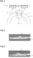
- FIG 7 illustrates the case of a sensor 2 encircling n elements.
- tube 1 alone is rotated around its longitudinal axis 3.
- This figure 7 illustrates in particular the reception shift, in number of receiving elements 7, of the waves received R due to the rotation of the tube 1.
- an ultrasonic shot E is emitted at time t 0
- this ultrasonic wave E enters the tube at time t i
- a reflected wave R emerges from tube 1 at time ti+ ⁇ t and is received by the receiving element 7 at time t f .
- the A-scan E i R j is actually located in the cell E i R (j ⁇ D él (i)) of the matrix, depending on the direction of rotation of the tube 1 relative to the direction of numbering of the elements 7 of the sensor 2. It is therefore necessary to take into account this offset D él in order to obtain a corrected matrix.
- a complete unblurred image can then be obtained according to the method described above by adding the amplitudes of the A-Scans of the corrected matrix obtained.
- FIG 8 illustrates an example of a matrix showing initial positions of the generated A-Scans, denoted E i R j (s), and corrected positions of said A-Scans in the matrix, denoted E i R j (d).
- the offset in number of elements D él calculated increases by one element with each new ultrasonic shot E compared to the initial ultrasonic shot E 1 .
- the first ultrasonic shot E 1 does not require any shift of the A-Scans EiR j (s) in the first row 10.
- the A-Scans EiR j (s) of the second row 10 are shifted by one column according to the direction of rotation of the tube 1, one column to the left in the illustrated example.
- the A-Scans EiR j (s) of the third row 10 are shifted by two columns to the left of the figure 8 , etc.
- the matrix is advantageously increased by a corresponding number of elements, the calculation of the sharp image taking into account elements 7 added virtually to the sensor 2, these elements 7 being added in the continuity of the elements 7 of the sensor 2, that is to say with an identical pitch.
- these A-Scans shifted outside the matrix can be ignored, but the sharp image is then calculated from a reduced number of A-Scans.
- the rotation of the tube 1 during the propagation of an ultrasonic shot E is such that the energy emitted by the same ultrasonic shot E is received by the elements 7 with a spatial reception shift.
- the tube 1 can have performed a rotation such that the reflected wave is not received by element 7 which should have been the targeted receiving element 7 if tube 1 had remained fixed, but by another element 7.
- FIG 9 illustrates this phenomenon of shift in reception of reflected waves during the propagation of the same ultrasonic shot E in tube 1.
- the sensor 2 is circular and the elements 7 are arranged in a circular fashion around the tube 1.
- an ultrasonic shot E n is emitted by the element n.
- This ultrasonic shot E n impacts the external surface 5 of the tube 1 at time ti, the defect 4 then being in a first position 14 relative to the sensor 2.
- the ultrasonic shot E n then propagates in the tube 1.
- tube 1 At time ti+dt, dt representing a rotation time of tube 1, tube 1 has performed a rotation of angle d ⁇ . At said time ti+dt, the ultrasonic shot E n has reached defect 4, defect 4 then having a second position 15, and a reflected wave16 resulting from the reflection of the ultrasonic shot E n on this defect 4 heads towards the external surface 5 of tube 1.
- the reflected wave 16 resulting from the reflection of the shot E n on the defect 4 returns to the external surface 5 of the tube 1 and exits the tube 1.
- the tube 1 has rotated about its longitudinal axis 3 by an angle k*d ⁇ .
- the propagation time k*dt of the ultrasonic shot E n in the tube 1 and/or the rotation speed V rot of the tube 1 are such that DL is negligible compared to the angular distance between the centers of two adjacent elements 7, and preferably compared to the distance separating the centers of two adjacent elements 7 divided by two, then it can be considered that the displacement of the tube 1 relative to the sensor 2 is negligible during a single ultrasonic shot E.
- the rotation of the tube 1 is therefore considered insufficient to create a reception shift during a single ultrasonic shot E
- the propagation time k*dt of the ultrasonic shot E n in the tube 1 and/or the rotation speed V rot of the tube 1 are such that DL is greater than the distance separating the centers of two adjacent elements 7, some of the reflected waves received by the receiving elements 7 should normally have been received by other elements. Consequently, the reflected waves R received by a receiving element 25 following the ultrasonic shot E emitted by an emitting element 26 are not representative of a propagation path identified for the association between said receiving element 25 and emitting element 26. A-Scan generated following the reception of the waves reflected by the receiving element 25 is therefore erroneous.
- the data E i R i recorded in the matrix i.e. the A-Scans corresponding to the waves received R i by the different elements 7 following each ultrasonic shot E, are themselves erroneous. It is then the A-Scans E i R i themselves which must be corrected in the matrix in order to obtain a clear image of the tube 1.
- the A-Scan correction consists of simulating a relative movement between tube 1 and sensor 2 to the reference position in order to obtain and generate corrected A-Scans corresponding to the A-Scans that would have been obtained in the absence of relative movement between tube 1 and sensor 2.
- the propagation medium of the ultrasonic wave E i between the sensor 2 and the tube 1 is not moving relative to the sensor 2, the reflected wave resulting from the impact of the shot E i on the external surface 5 of the tube 1, also called the interface echo, is not impacted by the rotation of the tube 1. This interface echo is therefore received normally by the i th transducer 7.
- the A-Scans are distorted and it is necessary to correct them by taking into account the rotation k*d ⁇ of tube 1 during the propagation of the ultrasonic shot E i in tube 1.
- the idea is to simulate a displacement of tube 1 to the reference position, typically an inversion of the movement of tube 1 when the reference position is the position at the instant of emission of the shot, to obtain corrected A-Scans substantially similar to the A-Scans which would be obtained in the absence of movement of the tube 1.
- the A-Scans resulting from the waves received R by the different elements 7 are generated in a first step then corrected in a second step.
- a first step in correcting A-Scans is to calculate a time increment dtp leading to a rotation dlp equal to the distance separating the center of two adjacent 7 elements. In the example illustrated in the figure 9 , this amounts to determining the angle ⁇ separating the center of two adjacent elements 7 and calculating the time dtp necessary for tube 1 to perform a rotation equivalent to this angle ⁇ .
- each block 17 is associated with a reference E i R j (t x -t y ) meaning that these are the waves received R during a duration t x -t y by a j th element following an i th ultrasonic shot.
- FIG 10 illustrates A-Scans 18 resulting from the reception by a plurality of elements 7 of the waves received R following the same ultrasonic shot E.
- each A-Scan 18 shown is generated from the waves received R by an element 7 during a succession of time intervals dtp.
- each of the A-Scans 18 is therefore divided into a plurality of time blocks 17, each time block 17 having a duration dtp corresponding to the rotation duration of the tube 1 necessary to cover the angle ⁇ separating the center of two adjacent elements 7.
- the different time blocks 17 are not all representative of a path identified between the transmitter element 26 and the receiver element 25 having made it possible to generate said A-Scan at the corresponding time of flight. Indeed, due to the rotation of the tube 1, these blocks 17 are generated from reflected waves received by the receiver element 25 but which should have been received by other elements 7, due to the rotation of the tube 1.
- the correction of an A-Scan therefore consists, for each A-Scan generated from the waves received R by an element 7, in selecting the blocks 17 which should have been received by another element 7 and associating said blocks 17 with the element 7 which should normally have received this block 17.
- this amounts to shifting the blocks 17 of an original A-Scan generated from the waves received R by an element 7 towards a respective target A-Scan which would normally have received the reflected waves corresponding to said block 17 in the absence of rotation of the tube 1.
- FIG 11 illustrates the different A-Scans corrected for the different elements 7 from the original A-Scans illustrated on the figure 10 .
- the i th blocks 17 are generated from the waves received R during the time ranges d ti to d ti+1 .
- the tube 1 has rotated about its longitudinal axis 3 by an angle i* ⁇ .
- the reflected waves represented in these i th blocks 17 have therefore been received by elements 7 offset by i blocks 17.
- the reflected wave received by a k th element 7 during the time range d ti to d ti+1 would, in the absence of relative movement between the sensor 2 and the tube 1, have been received by a k th element 7.
- the correction of the A-Scans 18 by simulation of the reverse movement of the tube 1, within the framework of a reference position corresponding to the instant of emission of the ultrasonic shot, can therefore be carried out by shifting the i th blocks 17 of the range d ti -d ti+1 by a number i of A-Scans 18 in the reverse direction of rotation of the tube 1.
- the blocks 17 d tpi -d tpi+1 of an A-Scan 18 generated by an n th element 7 are shifted towards the corresponding block 17, that is to say the block 17 of the range d tpi -d tpi+1 , of the element i+n,
- blocks 17 of A-Scans 18 illustrated on the figure 10 are shifted to simulate the reversal of the motion of tube 1.
- the i th blocks 17 of each line of the figure 10 are therefore shifted by i lines on the figure 11 to correct the A-Scans 18 of the figure 10 .
- each line therefore presents a corrected A-Scan 18 corresponding to the A-Scan 18 which would have been obtained by the element 7 associated with said line in the absence of relative movement between the tube 1 and the sensor 2.
- a corrected A-Scan 19 of the figure 11 corresponding to the fifth element 7, typically the fifth line of the figure 11 successively comprises from time t 0 to time tp4 , a first block 20 of the fifth line of the figure 10 , a second block 21 of the fourth line of the figure 10 , a third block 22 of the third line of the figure 10 and a fourth block 23 of the second line of the figure 10 .
- This corrected A-Scan 19 therefore includes blocks 20 to 23 corresponding to the waves received R by the different elements 7 within the framework of a rotation of the tube 1 relative to the sensor 2 and which would have were received only by the fifth element 7 if there had been no relative movement between tube 1 and sensor 2.
- the empty boxes correspond to blocks 17 having a zero amplitude signal for the A-Scans. These blocks 17 are not very damaging because they represent an empty amplitude signal which therefore does not modify the image obtained.
- the duration of the target A-Scan is advantageously increased by a number of blocks 17 corresponding in a similar manner to the virtual increase in the size of the matrix described above.
- the Figures 9 to 11 illustrate the case of a circular sensor 2 such that each element 7 covers a circular section of identical angle w around the tube 1.
- the rotation of the tube 1 causes a shift in the reception of the reflected waves R which is identical for all the elements 7 such that the duration d tp of cutting of the blocks 17 is identical for all the A-Scans 18.
- the arrangement of the elements 7 can be achieved in many ways.
- the elements 7 can be aligned along a longitudinal axis as is the case in the embodiment illustrated in the figures 1 And 3 . In this case, it is necessary to take into account the curvature of the tube 1 relative to the position of the different elements 7.
- the d tp can be calculated by taking into account other parameters such as the exit angle of the reflected waves or the projection of DL on the axis 9 of alignment of the elements 7. For each element 7, such a calculation leads to obtaining blocks 17 having different durations depending on the relative location of the element 7 relative to the tube 1. Similarly, it is necessary to take into account this difference in duration of the blocks 17 between the different elements 7 to determine the offset of the blocks 17 between the different elements 7.
- the relative displacement between the tube 1 and the sensor 2 corrected in the example given above for illustrative purposes is an angular displacement relative to the longitudinal axis 3 of the tube 1.
- this displacement could be of another nature such as for example a translation along said longitudinal axis 3 or other.
- FIG. 12 illustrates a raw image (left part of the figure) and the amplitudes of the pixels of column 150 of this raw image (right part of the figure).
- This raw image is generated from the raw data, i.e. before correction according to the invention, acquired during a relative movement between the tube 1 and the sensor 2.
- This raw image shows the defect 4 in the tube 1 but has a significant blurring which does not allow the defect 4 to be precisely characterized.
- FIG 13 illustrates the image corrected according to the method described above using partial images and the amplitudes of the pixels of column 150 of this corrected image.
- This corrected image is clear and easily allows the defect 4 to be characterized precisely and reliably despite the fact that the data for generating this corrected image were obtained during a relative movement between the tube 1 and the sensor 2.
- the amplitude gain on the defect provided by the correction is 5.7 dB.
Landscapes
- Physics & Mathematics (AREA)
- Health & Medical Sciences (AREA)
- Life Sciences & Earth Sciences (AREA)
- Chemical & Material Sciences (AREA)
- Analytical Chemistry (AREA)
- Biochemistry (AREA)
- General Health & Medical Sciences (AREA)
- General Physics & Mathematics (AREA)
- Immunology (AREA)
- Pathology (AREA)
- Acoustics & Sound (AREA)
- Engineering & Computer Science (AREA)
- Signal Processing (AREA)
- Investigating Or Analyzing Materials By The Use Of Ultrasonic Waves (AREA)
Claims (14)
- Verfahren zur dynamischen Erfassung von Daten, die für ein zu prüfendes metallisches Teil (1) repräsentativ sind, wobei das Verfahren umfasst:- einen Schritt des Erfassens von Daten an dem zu prüfenden Teil (1), wobei die Daten von einem Mehrelementesensor (2) erhalten werden, wobei der Sensor (2) Sendeelemente und Empfangselemente umfasst, wobei die Sendeelemente dazu ausgestaltet sind, einen jeweiligen Ultraschallschuss (E) in Richtung des zu prüfenden Teils (1) zu senden, so dass sich der Ultraschallschuss (E) durch das zu prüfende Teil (1) hindurch ausbreitet, wobei ein Kopplungsmittel das zu prüfende Teil (1) von dem Mehrelementesensor (2) trennt, um die Ausbreitung von Ultraschallwellen zu ermöglichen, wobei die Empfangselemente dazu ausgestaltet sind, von dem zu prüfenden Teil (1) reflektierte Wellen (R), die aus dem Ultraschallschuss (E) stammen, zu empfangen, wobei der Schritt des Erfassens umfasst:wobei die für das zu prüfende Teil (1) repräsentativen Daten, für jedes Empfangselement, ein jeweiliges A-Bild (18) umfassen, das für eine Intensität der von dem Empfänger empfangenen Wellen in Abhängigkeit von der Hörzeit des Empfangselements repräsentativ ist, und ferner, während des Schritts des Erfassens von Daten, einen Schritt des Bewegens, entlang und/oder um eine Achse, von einem unter dem zu prüfenden Teil (1) und dem Sensor (2), so dass eine relative Bewegung zwischen dem Sensor (2) und dem zu prüfenden Teil (1) erzeugt wird, und ferner einen Schritt des Erzeugens von korrigierten Daten, die für das zu prüfende Teil (1) repräsentativ sind, wobei der Schritt des Erzeugens der korrigierten Daten umfasst:- Senden eines Sende-Ultraschallschusses (E) von einem Sendeelement aus, und- Empfangen durch die Empfangselemente, während einer Hördauer, der Ultraschallwellen, wobei die empfangenen Ultraschallwellen eine von dem zu prüfenden Teil (1) reflektierte Welle umfassen, die aus dem gesendeten Ultraschallschuss (E) stammt, wobei das Verfahren ferner einen Schritt des Erzeugens von für das zu prüfende Teil (1) repräsentativen Daten in Abhängigkeit von den von den Empfangselementen empfangenen Wellen umfasst,- Berechnen einer Korrekturbewegung in Abhängigkeit von der relativen Bewegung zwischen dem Sensor (2) und dem zu prüfenden Teil (1), von einer Referenzposition und von einer Dauer in Bezug auf einen Referenzzeitpunkt, wobei die Referenzposition einer relativen Position zwischen dem Sensor (2) und dem zu prüfenden Teil (1) zu dem Referenzzeitpunkt entspricht, wobei der Referenzzeitpunkt während des Schritts des Erfassens von Daten stattfindet, wobei die Korrekturbewegung einer relativen Bewegung zwischen dem Sensor (2) und dem zu prüfenden Teil (1) bis zu der Referenzposition von einer relativen Position aus entspricht, die der relativen Position zwischen dem Sensor (2) und dem zu prüfenden Teil (1) zu einem Zeitpunkt der Dauer in Bezug auf den Referenzzeitpunkt entspricht, und- Anwenden auf die für das zu prüfende Teil (1) repräsentativen Daten einer Korrektur in Abhängigkeit von der berechneten Korrekturbewegung, so dass die korrigierten Daten erzeugt werden, indem eine relative Bewegung zwischen dem Sensor (2) und dem zu prüfenden Teil (1) von einer relativen Position zwischen dem Sensor (2) und dem zu prüfenden Teil (1) zu dem Zeitpunkt der Dauer aus bis zu der Referenzposition simuliert wird.
- Verfahren zur dynamischen Erfassung nach Anspruch 1, wobei der Schritt des Erzeugens der korrigierten Daten ein Auswählen der Referenzposition umfasst.
- Verfahren zur dynamischen Erfassung nach Anspruch 1 oder 2, wobei der Schritt des Erfassens von Daten umfasst- das Senden einer Vielzahl von Ultraschallschüssen (E), und- für jeden Schritt des Sendens eines Ultraschallsignals einen entsprechenden Schritt, während einer jeweiligen Hördauer, des Empfangens der Ultraschallwellen durch die Empfangselemente des Sensors (2), wobei die empfangenen Ultraschallwellen mindestens eine von dem zu prüfenden Teil (1) reflektierte Welle umfassen, die aus dem entsprechenden gesendeten Ultraschallschuss stammt,und wobei der Referenzzeitpunkt ein Sendezeitpunkt eines Ultraschallschusses der Vielzahl von Ultraschallschüssen ist und die Dauer ein Vielfaches der Dauer ist, die zwei aufeinander folgende Ultraschallschüsse der Vielzahl von Ultraschallschüssen trennt, so dass die Korrekturbewegung in Abhängigkeit von der relativen Bewegung zwischen dem Sensor (2) und dem zu prüfenden Teil (1) zwischen dem Senden von zwei verschiedenen Ultraschallschüssen berechnet wird.
- Verfahren zur dynamischen Erfassung nach Anspruch 3, wobei die für das zu prüfende Teil (1) repräsentativen Daten ein Teilbild für die Vielzahl von bei dem Schritt des Erfassens gesendeten Ultraschallschüssen (E) umfasst, wobei das Anwenden einer Korrektur auf die für das zu prüfende Teil (1) repräsentativen Daten einen Schritt des Änderns des Teilbilds umfassen, um eine Bewegung des zu prüfenden Teils (1) von der relativen Position zwischen dem Sensor (2) und dem zu prüfenden Teil (1) aus, die auf dem Teilbild dargestellt ist, bis zu der Referenzposition zu simulieren, um ein korrigiertes Teilbild zu erzeugen.
- Verfahren zur dynamischen Erfassung nach Anspruch 4, umfassend ferner einen Schritt des Erzeugens eines für das zu prüfende Teil (1) repräsentativen Bilds durch Überlagerung einer Vielzahl von korrigierten Teilbildern.
- Verfahren zur dynamischen Erfassung nach Anspruch 3, wobei die für das zu prüfende Teil (1) repräsentativen Daten eine Matrix umfassen, wobei jede Zeile der Matrix die für das zu prüfende Teil (1) repräsentativen Daten umfasst, die nach einem jeweiligen Ultraschallschuss (E) erzeugt werden, wobei jede Spalte der Matrix die für das zu prüfende Teil (1) repräsentativen Daten umfasst, die ausgehend von einem jeweiligen Empfangselement des Sensors (2) erzeugt werden, wobei das Berechnen der Korrekturbewegung für jeden Ultraschallschuss (E) ein Berechnen eines jeweiligen Empfangsversatzes um eine Anzahl von Empfangselementen des Sensors (2) umfasst, wobei das Anwenden einer Korrektur für jede Zeile der Matrix das Anwenden für Zellen der Zeile eines Versatzes, um eine Anzahl von Spalten, des Inhalts der Zellen des entsprechenden Empfangsversatzes umfasst.
- Verfahren zur dynamischen Erfassung nach einem der Ansprüche 1 bis 6, wobei die Hördauer einen Beginnzeitpunkt aufweist, der gleich dem Sendezeitpunkt des Ultraschallschusses ist, wobei die Hördauer größer oder gleich einer maximalen Flugzeit zwischen dem Senden des Ultraschallschusses und dem Empfangen durch ein Empfangselement des Sensors einer von einer Seite des zu prüfenden Teils (1), die zu dem Sensor entgegengesetzt ist, reflektierten Welle ist, so dass die Korrekturbewegung in Abhängigkeit von der relativen Bewegung zwischen dem Sensor (2) und dem zu prüfenden Teil (1) während einer Laufzeit zwischen einem Sendezeitpunkt des Ultraschallschusses (E) und einem Empfangszeitpunkt der von dem zu prüfenden Teil (1) reflektierten Wellen, die aus dem Ultraschallschuss (E) stammen, durch die Empfangselemente berechnet wird.
- Verfahren zur dynamischen Erfassung nach einem der Ansprüche 1 bis 7, wobei das Berechnen der Korrekturbewegung das Zerlegen, für die jeweiligen A-Bilder (18) der Empfangselemente, in eine Vielzahl von Zeitblöcken (17) umfasst.
- Verfahren zur dynamischen Erfassung nach Anspruch 8, wobei das Berechnen der Korrekturbewegung das Berechnen einer Signalempfangsdauer (dtp) durch ein Empfangselement der Vielzahl von Empfangselementen in Abhängigkeit von der relativen Bewegung zwischen dem Sensor (2) und dem zu prüfenden Teil (1) umfasst und wobei jeder Zeitblock (17) eines A-Bilds (18) eine Dauer gleich der Empfangsdauer (dtp) des Empfangselements für die relative Bewegung des Sensors in Bezug auf das zu prüfende Teil (1) aufweist.
- Verfahren zur dynamischen Erfassung nach Anspruch 9, wobei das Berechnen der Korrekturbewegung das Berechnen eines Versatzes um eine Anzahl von Empfangselementen in Abhängigkeit von den relativen Positionen der Empfangselemente, von den Signalempfangsdauern (dtp) der Empfangselemente und von dem Sendezeitpunkt des Ultraschallsignals (E) umfasst.
- Verfahren zur dynamischen Erfassung nach Anspruch 10, wobei, für einen gegebenen Zeitblock (17) eines ursprünglichen A-Bilds, der Versatz gleich der maximalen Anzahl von aufeinander folgenden Empfangselementen entlang einer Richtung einer relativen Bewegung zwischen dem Sensor (2) und dem zu prüfenden Teil (1) und ausgehend von dem Empfangselement, das die reflektierten Wellen des ursprünglichen A-Bilds empfangen hat, ist, dessen kumulierte Summe der Signalempfangsdauern (dtp) kleiner als die Dauer ist, die zwischen dem Referenzzeitpunkt und dem Beginnzeitpunkt des Zeitblocks (17) vergangen ist.
- Verfahren zur dynamischen Erfassung nach Anspruch 11, wobei das Anwenden einer Korrektur für mindestens einen Zeitblock (17) des ursprünglichen A-Bilds das Ersetzen eines Abschnitts eines Ziel-A-Bilds durch den Zeitblock (17) umfasst, wobei das Ziel-A-Bild dem A-Bild entspricht, das ausgehend von dem n-ten Empfangselement erzeugt wird, das auf den Empfänger, der die reflektierten Wellen des ursprünglichen A-Bilds empfangen hat, in Richtung der relativen Bewegung zwischen dem Sensor (2) und dem zu prüfenden Teil (1) folgt, wobei n der berechnete Versatz ist, wobei der Abschnitt des Ziel-A-Bilds den gleichen Beginn- und Endezeitpunkt wie der Zeitblock aufweist.
- Verfahren zur dynamischen Erfassung nach einem der Ansprüche 1 bis 12, wobei die relative Bewegung zwischen dem Sensor (2) und dem zu prüfenden Teil (1) aus einer Bewegung des zu prüfenden Teils (1) und dem Halten des Sensors (2) in einer Fixposition während der Bewegung des zu prüfenden Teils (1) resultiert, wobei die Bewegung des zu prüfenden Teils (1) eine Winkelkomponente um eine Rotationsachse (3) aufweist, wobei das Berechnen einer Korrekturbewegung einen Schritt des Berechnens der Winkelbewegung (dθ) des zu prüfenden Teils (1) während der relativen Bewegung zwischen dem Sensor (2) und dem zu prüfenden Teil (1) umfasst.
- Verfahren zur dynamischen Erfassung nach Anspruch 13, wobei das Berechnen einer Korrekturbewegung einen Schritt des Berechnens der Winkelbewegung des zu prüfenden Teils (1) während der relativen Bewegung zwischen dem Sensor (2) und dem zu prüfenden Teil (1) umfasst und wobei das Korrigieren der für das zu prüfende Teil (1) repräsentativen Daten das Simulieren einer Rotation des zu prüfenden Teils (1) um seine Rotationsachse (3) gemäß einem Winkel einer Winkelbewegung des zu prüfenden Teils (1) während des Schritts des Erfassens bis zu der Referenzposition umfasst.
Applications Claiming Priority (2)
| Application Number | Priority Date | Filing Date | Title |
|---|---|---|---|
| FR2008092A FR3113136A1 (fr) | 2020-07-30 | 2020-07-30 | Procédé de contrôle dynamique par imagerie ultrasonore |
| PCT/FR2021/051424 WO2022023681A1 (fr) | 2020-07-30 | 2021-07-29 | Procédé de contrôle dynamique par imagerie ultrasonore |
Publications (2)
| Publication Number | Publication Date |
|---|---|
| EP4189381A1 EP4189381A1 (de) | 2023-06-07 |
| EP4189381B1 true EP4189381B1 (de) | 2025-01-08 |
Family
ID=74125282
Family Applications (1)
| Application Number | Title | Priority Date | Filing Date |
|---|---|---|---|
| EP21799078.7A Active EP4189381B1 (de) | 2020-07-30 | 2021-07-29 | Verfahren zur dynamischen kontrolle mittels ultraschallbildgebung |
Country Status (9)
| Country | Link |
|---|---|
| US (1) | US12345685B2 (de) |
| EP (1) | EP4189381B1 (de) |
| JP (1) | JP7592842B2 (de) |
| CN (1) | CN116034272B (de) |
| AR (1) | AR123081A1 (de) |
| CA (1) | CA3186352A1 (de) |
| FR (1) | FR3113136A1 (de) |
| PL (1) | PL4189381T3 (de) |
| WO (1) | WO2022023681A1 (de) |
Families Citing this family (1)
| Publication number | Priority date | Publication date | Assignee | Title |
|---|---|---|---|---|
| CN115097007B (zh) * | 2022-08-25 | 2023-01-20 | 哈尔滨长川超声仪器科技有限公司 | 轴承内部组织全息超声检测方法 |
Family Cites Families (15)
| Publication number | Priority date | Publication date | Assignee | Title |
|---|---|---|---|---|
| JP3043873B2 (ja) * | 1991-11-29 | 2000-05-22 | フクダ電子株式会社 | 超音波開口面合成装置 |
| EP0705073A1 (de) * | 1994-04-25 | 1996-04-10 | Thermotrex Corporation | Bilddarstellung mittels optischer signale |
| US6162174A (en) * | 1998-09-16 | 2000-12-19 | Siemens Medical Systems, Inc. | Method for compensating for object movement in ultrasound images |
| JP4564286B2 (ja) * | 2004-06-14 | 2010-10-20 | 株式会社東芝 | 3次元超音波画像化装置 |
| EP1757955B1 (de) * | 2005-08-24 | 2010-11-17 | Medison Co., Ltd. | Vorrichtung und Verfahren zum Bearbeiten eines Ultraschallbildes |
| US10226234B2 (en) * | 2011-12-01 | 2019-03-12 | Maui Imaging, Inc. | Motion detection using ping-based and multiple aperture doppler ultrasound |
| US10429444B2 (en) | 2012-01-31 | 2019-10-01 | Primearth Ev Energy Co., Ltd. | State of charge detection device |
| US20140293736A1 (en) * | 2013-03-31 | 2014-10-02 | National Taiwan University | Low complexity motion compensating beamforming system and method thereof |
| KR102053800B1 (ko) * | 2013-12-17 | 2019-12-09 | 온타리오 파워제너레이션 인코퍼레이티드 | 향상된 초음파 탐지 |
| KR102164456B1 (ko) * | 2014-02-13 | 2020-10-12 | 삼성전자주식회사 | 초음파 측정 장치 및 초음파 측정 방법 |
| JP6467859B2 (ja) * | 2014-10-20 | 2019-02-13 | 新日鐵住金株式会社 | 超音波探傷方法及び装置 |
| FR3051913B1 (fr) * | 2016-05-25 | 2020-12-11 | Electricite De France | Procede de detection par ultrasons de defauts dans un materiau |
| CN107949331B (zh) * | 2016-06-30 | 2021-04-13 | 深圳迈瑞生物医疗电子股份有限公司 | 超声流体频谱多普勒成像方法和系统 |
| US11054398B2 (en) | 2018-03-08 | 2021-07-06 | Mitsubishi Heavy Industries, Ltd. | Ultrasonic inspection method, ultrasonic inspection device, and computer-readable storage medium |
| JP7233646B2 (ja) | 2018-03-08 | 2023-03-07 | 三菱重工業株式会社 | 超音波検査方法、超音波検査装置およびプログラム |
-
2020
- 2020-07-30 FR FR2008092A patent/FR3113136A1/fr active Pending
-
2021
- 2021-07-29 PL PL21799078.7T patent/PL4189381T3/pl unknown
- 2021-07-29 CA CA3186352A patent/CA3186352A1/fr active Pending
- 2021-07-29 JP JP2023506144A patent/JP7592842B2/ja active Active
- 2021-07-29 WO PCT/FR2021/051424 patent/WO2022023681A1/fr not_active Ceased
- 2021-07-29 AR ARP210102111A patent/AR123081A1/es unknown
- 2021-07-29 US US18/006,918 patent/US12345685B2/en active Active
- 2021-07-29 EP EP21799078.7A patent/EP4189381B1/de active Active
- 2021-07-29 CN CN202180053405.XA patent/CN116034272B/zh active Active
Also Published As
| Publication number | Publication date |
|---|---|
| PL4189381T3 (pl) | 2025-04-07 |
| EP4189381A1 (de) | 2023-06-07 |
| CN116034272A (zh) | 2023-04-28 |
| CN116034272B (zh) | 2026-01-06 |
| US12345685B2 (en) | 2025-07-01 |
| AR123081A1 (es) | 2022-10-26 |
| CA3186352A1 (fr) | 2022-02-03 |
| FR3113136A1 (fr) | 2022-02-04 |
| JP7592842B2 (ja) | 2024-12-02 |
| WO2022023681A1 (fr) | 2022-02-03 |
| US20230266278A1 (en) | 2023-08-24 |
| JP2023536146A (ja) | 2023-08-23 |
Similar Documents
| Publication | Publication Date | Title |
|---|---|---|
| EP1454132B1 (de) | Ultraschallvorrichtung zur zerstörungsfreien prüfung von metallurgischen produkten | |
| EP0591061B1 (de) | Verfahren und Vorrichtung zur akustischen Prüfung mit Zeitumkehrsignalen | |
| EP3642609B1 (de) | Vorrichtung und verfahren zur zerstörungsfreien prüfung eines rohrförmigen produkts mit einer komplexen form | |
| EP2976635A1 (de) | Vorrichtung und verfahren zur zerstörungsfreien steuerung von schlauchförmigen produkten unter verwendung von elektroakustischen phasengesteuerten netzwerken, insbesondere vor ort | |
| EP3391039B1 (de) | Vorrichtung zur steuerung und messung von schweissdefekten auf einer zylindrischen wand und verfahren zur implementierung dafür | |
| EP0959350B1 (de) | Ultraschallprüfverfahren für zylindrische Werkstücke | |
| EP0598661B1 (de) | Verfahren und Vorrichtung für industrielle Ultraschallsteuerung von drehenden Teilen | |
| EP4189381B1 (de) | Verfahren zur dynamischen kontrolle mittels ultraschallbildgebung | |
| EP2936141A1 (de) | Vorrichtung und verfahren zur zerstörungsfreien steuerung von metallprofilen | |
| EP4095527B1 (de) | Verfahren und system zur ultraschalldetektion von internen defekten eines bauteils, insbesondere für ein luftfahrzeug | |
| EP3387422A1 (de) | Verfahren zur ultraschallprüfung eines objekts | |
| CA3123111A1 (fr) | Procede de reconstruction d'une surface tridimensionnelle par un capteur matriciel ultrasonore | |
| EP4384775B1 (de) | Methode zur rekonstruktion eines dickenprofils eines zu inspizierenden objekts | |
| FR2796153A1 (fr) | Controle non destructif a capteurs ultrasonores repartis | |
| EP4630802A1 (de) | Verfahren zur erkennung von rissen in einem rohrförmigen rohr | |
| FR3161031A1 (fr) | Procédé et ensemble de contrôle non destructif par ultrasons d’une barre métallique longitudinale | |
| FR2907901A1 (fr) | Procede de controle non destructif par ultrasons et sonde de mesure pour la mise en oeuvre du procede | |
| FR2855271A1 (fr) | Procede pour l'exploitation et l'analyse d'une structure volumique |
Legal Events
| Date | Code | Title | Description |
|---|---|---|---|
| STAA | Information on the status of an ep patent application or granted ep patent |
Free format text: STATUS: UNKNOWN |
|
| STAA | Information on the status of an ep patent application or granted ep patent |
Free format text: STATUS: THE INTERNATIONAL PUBLICATION HAS BEEN MADE |
|
| PUAI | Public reference made under article 153(3) epc to a published international application that has entered the european phase |
Free format text: ORIGINAL CODE: 0009012 |
|
| STAA | Information on the status of an ep patent application or granted ep patent |
Free format text: STATUS: REQUEST FOR EXAMINATION WAS MADE |
|
| 17P | Request for examination filed |
Effective date: 20230209 |
|
| AK | Designated contracting states |
Kind code of ref document: A1 Designated state(s): AL AT BE BG CH CY CZ DE DK EE ES FI FR GB GR HR HU IE IS IT LI LT LU LV MC MK MT NL NO PL PT RO RS SE SI SK SM TR |
|
| DAV | Request for validation of the european patent (deleted) | ||
| DAX | Request for extension of the european patent (deleted) | ||
| GRAP | Despatch of communication of intention to grant a patent |
Free format text: ORIGINAL CODE: EPIDOSNIGR1 |
|
| STAA | Information on the status of an ep patent application or granted ep patent |
Free format text: STATUS: GRANT OF PATENT IS INTENDED |
|
| INTG | Intention to grant announced |
Effective date: 20241029 |
|
| GRAS | Grant fee paid |
Free format text: ORIGINAL CODE: EPIDOSNIGR3 |
|
| GRAA | (expected) grant |
Free format text: ORIGINAL CODE: 0009210 |
|
| STAA | Information on the status of an ep patent application or granted ep patent |
Free format text: STATUS: THE PATENT HAS BEEN GRANTED |
|
| AK | Designated contracting states |
Kind code of ref document: B1 Designated state(s): AL AT BE BG CH CY CZ DE DK EE ES FI FR GB GR HR HU IE IS IT LI LT LU LV MC MK MT NL NO PL PT RO RS SE SI SK SM TR |
|
| REG | Reference to a national code |
Ref country code: GB Ref legal event code: FG4D Free format text: NOT ENGLISH |
|
| REG | Reference to a national code |
Ref country code: CH Ref legal event code: EP |
|
| REG | Reference to a national code |
Ref country code: DE Ref legal event code: R096 Ref document number: 602021024739 Country of ref document: DE |
|
| REG | Reference to a national code |
Ref country code: IE Ref legal event code: FG4D Free format text: LANGUAGE OF EP DOCUMENT: FRENCH |
|
| REG | Reference to a national code |
Ref country code: LT Ref legal event code: MG9D |
|
| REG | Reference to a national code |
Ref country code: NL Ref legal event code: MP Effective date: 20250108 |
|
| REG | Reference to a national code |
Ref country code: AT Ref legal event code: MK05 Ref document number: 1758629 Country of ref document: AT Kind code of ref document: T Effective date: 20250108 |
|
| PG25 | Lapsed in a contracting state [announced via postgrant information from national office to epo] |
Ref country code: NL Free format text: LAPSE BECAUSE OF FAILURE TO SUBMIT A TRANSLATION OF THE DESCRIPTION OR TO PAY THE FEE WITHIN THE PRESCRIBED TIME-LIMIT Effective date: 20250108 |
|
| PG25 | Lapsed in a contracting state [announced via postgrant information from national office to epo] |
Ref country code: RS Free format text: LAPSE BECAUSE OF FAILURE TO SUBMIT A TRANSLATION OF THE DESCRIPTION OR TO PAY THE FEE WITHIN THE PRESCRIBED TIME-LIMIT Effective date: 20250408 |
|
| PG25 | Lapsed in a contracting state [announced via postgrant information from national office to epo] |
Ref country code: FI Free format text: LAPSE BECAUSE OF FAILURE TO SUBMIT A TRANSLATION OF THE DESCRIPTION OR TO PAY THE FEE WITHIN THE PRESCRIBED TIME-LIMIT Effective date: 20250108 |
|
| PGFP | Annual fee paid to national office [announced via postgrant information from national office to epo] |
Ref country code: PL Payment date: 20250620 Year of fee payment: 5 |
|
| PG25 | Lapsed in a contracting state [announced via postgrant information from national office to epo] |
Ref country code: ES Free format text: LAPSE BECAUSE OF FAILURE TO SUBMIT A TRANSLATION OF THE DESCRIPTION OR TO PAY THE FEE WITHIN THE PRESCRIBED TIME-LIMIT Effective date: 20250108 |
|
| PGFP | Annual fee paid to national office [announced via postgrant information from national office to epo] |
Ref country code: GB Payment date: 20250619 Year of fee payment: 5 |
|
| PG25 | Lapsed in a contracting state [announced via postgrant information from national office to epo] |
Ref country code: IS Free format text: LAPSE BECAUSE OF FAILURE TO SUBMIT A TRANSLATION OF THE DESCRIPTION OR TO PAY THE FEE WITHIN THE PRESCRIBED TIME-LIMIT Effective date: 20250508 |
|
| PGFP | Annual fee paid to national office [announced via postgrant information from national office to epo] |
Ref country code: NO Payment date: 20250623 Year of fee payment: 5 |
|
| PG25 | Lapsed in a contracting state [announced via postgrant information from national office to epo] |
Ref country code: HR Free format text: LAPSE BECAUSE OF FAILURE TO SUBMIT A TRANSLATION OF THE DESCRIPTION OR TO PAY THE FEE WITHIN THE PRESCRIBED TIME-LIMIT Effective date: 20250108 |
|
| PG25 | Lapsed in a contracting state [announced via postgrant information from national office to epo] |
Ref country code: LV Free format text: LAPSE BECAUSE OF FAILURE TO SUBMIT A TRANSLATION OF THE DESCRIPTION OR TO PAY THE FEE WITHIN THE PRESCRIBED TIME-LIMIT Effective date: 20250108 Ref country code: PT Free format text: LAPSE BECAUSE OF FAILURE TO SUBMIT A TRANSLATION OF THE DESCRIPTION OR TO PAY THE FEE WITHIN THE PRESCRIBED TIME-LIMIT Effective date: 20250508 |
|
| PGFP | Annual fee paid to national office [announced via postgrant information from national office to epo] |
Ref country code: FR Payment date: 20250619 Year of fee payment: 5 |
|
| PG25 | Lapsed in a contracting state [announced via postgrant information from national office to epo] |
Ref country code: BG Free format text: LAPSE BECAUSE OF FAILURE TO SUBMIT A TRANSLATION OF THE DESCRIPTION OR TO PAY THE FEE WITHIN THE PRESCRIBED TIME-LIMIT Effective date: 20250108 Ref country code: GR Free format text: LAPSE BECAUSE OF FAILURE TO SUBMIT A TRANSLATION OF THE DESCRIPTION OR TO PAY THE FEE WITHIN THE PRESCRIBED TIME-LIMIT Effective date: 20250409 |
|
| PG25 | Lapsed in a contracting state [announced via postgrant information from national office to epo] |
Ref country code: AT Free format text: LAPSE BECAUSE OF FAILURE TO SUBMIT A TRANSLATION OF THE DESCRIPTION OR TO PAY THE FEE WITHIN THE PRESCRIBED TIME-LIMIT Effective date: 20250108 |
|
| PG25 | Lapsed in a contracting state [announced via postgrant information from national office to epo] |
Ref country code: SE Free format text: LAPSE BECAUSE OF FAILURE TO SUBMIT A TRANSLATION OF THE DESCRIPTION OR TO PAY THE FEE WITHIN THE PRESCRIBED TIME-LIMIT Effective date: 20250108 |
|
| PG25 | Lapsed in a contracting state [announced via postgrant information from national office to epo] |
Ref country code: SM Free format text: LAPSE BECAUSE OF FAILURE TO SUBMIT A TRANSLATION OF THE DESCRIPTION OR TO PAY THE FEE WITHIN THE PRESCRIBED TIME-LIMIT Effective date: 20250108 |
|
| REG | Reference to a national code |
Ref country code: DE Ref legal event code: R097 Ref document number: 602021024739 Country of ref document: DE |
|
| PG25 | Lapsed in a contracting state [announced via postgrant information from national office to epo] |
Ref country code: DK Free format text: LAPSE BECAUSE OF FAILURE TO SUBMIT A TRANSLATION OF THE DESCRIPTION OR TO PAY THE FEE WITHIN THE PRESCRIBED TIME-LIMIT Effective date: 20250108 |
|
| PGFP | Annual fee paid to national office [announced via postgrant information from national office to epo] |
Ref country code: DE Payment date: 20250620 Year of fee payment: 5 |
|
| PG25 | Lapsed in a contracting state [announced via postgrant information from national office to epo] |
Ref country code: EE Free format text: LAPSE BECAUSE OF FAILURE TO SUBMIT A TRANSLATION OF THE DESCRIPTION OR TO PAY THE FEE WITHIN THE PRESCRIBED TIME-LIMIT Effective date: 20250108 Ref country code: CZ Free format text: LAPSE BECAUSE OF FAILURE TO SUBMIT A TRANSLATION OF THE DESCRIPTION OR TO PAY THE FEE WITHIN THE PRESCRIBED TIME-LIMIT Effective date: 20250108 |
|
| PG25 | Lapsed in a contracting state [announced via postgrant information from national office to epo] |
Ref country code: RO Free format text: LAPSE BECAUSE OF FAILURE TO SUBMIT A TRANSLATION OF THE DESCRIPTION OR TO PAY THE FEE WITHIN THE PRESCRIBED TIME-LIMIT Effective date: 20250108 |
|
| PG25 | Lapsed in a contracting state [announced via postgrant information from national office to epo] |
Ref country code: SK Free format text: LAPSE BECAUSE OF FAILURE TO SUBMIT A TRANSLATION OF THE DESCRIPTION OR TO PAY THE FEE WITHIN THE PRESCRIBED TIME-LIMIT Effective date: 20250108 |
|
| PLBE | No opposition filed within time limit |
Free format text: ORIGINAL CODE: 0009261 |
|
| STAA | Information on the status of an ep patent application or granted ep patent |
Free format text: STATUS: NO OPPOSITION FILED WITHIN TIME LIMIT |
|
| REG | Reference to a national code |
Ref country code: CH Ref legal event code: L10 Free format text: ST27 STATUS EVENT CODE: U-0-0-L10-L00 (AS PROVIDED BY THE NATIONAL OFFICE) Effective date: 20251119 |
|
| 26N | No opposition filed |
Effective date: 20251009 |
|
| PG25 | Lapsed in a contracting state [announced via postgrant information from national office to epo] |
Ref country code: IT Free format text: LAPSE BECAUSE OF FAILURE TO SUBMIT A TRANSLATION OF THE DESCRIPTION OR TO PAY THE FEE WITHIN THE PRESCRIBED TIME-LIMIT Effective date: 20250108 |
|
| REG | Reference to a national code |
Ref country code: CH Ref legal event code: H13 Free format text: ST27 STATUS EVENT CODE: U-0-0-H10-H13 (AS PROVIDED BY THE NATIONAL OFFICE) Effective date: 20260224 |
|
| PG25 | Lapsed in a contracting state [announced via postgrant information from national office to epo] |
Ref country code: LU Free format text: LAPSE BECAUSE OF NON-PAYMENT OF DUE FEES Effective date: 20250729 |
|
| REG | Reference to a national code |
Ref country code: BE Ref legal event code: MM Effective date: 20250731 |
|
| PG25 | Lapsed in a contracting state [announced via postgrant information from national office to epo] |
Ref country code: BE Free format text: LAPSE BECAUSE OF NON-PAYMENT OF DUE FEES Effective date: 20250731 |