EP4384775B1 - Methode zur rekonstruktion eines dickenprofils eines zu inspizierenden objekts - Google Patents
Methode zur rekonstruktion eines dickenprofils eines zu inspizierenden objekts Download PDFInfo
- Publication number
- EP4384775B1 EP4384775B1 EP22761241.3A EP22761241A EP4384775B1 EP 4384775 B1 EP4384775 B1 EP 4384775B1 EP 22761241 A EP22761241 A EP 22761241A EP 4384775 B1 EP4384775 B1 EP 4384775B1
- Authority
- EP
- European Patent Office
- Prior art keywords
- inspected
- sensor
- point
- reconstruction
- firing
- Prior art date
- Legal status (The legal status is an assumption and is not a legal conclusion. Google has not performed a legal analysis and makes no representation as to the accuracy of the status listed.)
- Active
Links
Images
Classifications
-
- G—PHYSICS
- G01—MEASURING; TESTING
- G01N—INVESTIGATING OR ANALYSING MATERIALS BY DETERMINING THEIR CHEMICAL OR PHYSICAL PROPERTIES
- G01N29/00—Investigating or analysing materials by the use of ultrasonic, sonic or infrasonic waves; Visualisation of the interior of objects by transmitting ultrasonic or sonic waves through the object
- G01N29/22—Details, e.g. general constructional or apparatus details
- G01N29/26—Arrangements for orientation or scanning by relative movement of the head and the sensor
- G01N29/262—Arrangements for orientation or scanning by relative movement of the head and the sensor by electronic orientation or focusing, e.g. with phased arrays
-
- G—PHYSICS
- G01—MEASURING; TESTING
- G01B—MEASURING LENGTH, THICKNESS OR SIMILAR LINEAR DIMENSIONS; MEASURING ANGLES; MEASURING AREAS; MEASURING IRREGULARITIES OF SURFACES OR CONTOURS
- G01B17/00—Measuring arrangements characterised by the use of infrasonic, sonic or ultrasonic vibrations
- G01B17/02—Measuring arrangements characterised by the use of infrasonic, sonic or ultrasonic vibrations for measuring thickness
-
- G—PHYSICS
- G01—MEASURING; TESTING
- G01N—INVESTIGATING OR ANALYSING MATERIALS BY DETERMINING THEIR CHEMICAL OR PHYSICAL PROPERTIES
- G01N29/00—Investigating or analysing materials by the use of ultrasonic, sonic or infrasonic waves; Visualisation of the interior of objects by transmitting ultrasonic or sonic waves through the object
- G01N29/04—Analysing solids
- G01N29/041—Analysing solids on the surface of the material, e.g. using Lamb, Rayleigh or shear waves
-
- G—PHYSICS
- G01—MEASURING; TESTING
- G01N—INVESTIGATING OR ANALYSING MATERIALS BY DETERMINING THEIR CHEMICAL OR PHYSICAL PROPERTIES
- G01N29/00—Investigating or analysing materials by the use of ultrasonic, sonic or infrasonic waves; Visualisation of the interior of objects by transmitting ultrasonic or sonic waves through the object
- G01N29/04—Analysing solids
- G01N29/043—Analysing solids in the interior, e.g. by shear waves
-
- G—PHYSICS
- G01—MEASURING; TESTING
- G01N—INVESTIGATING OR ANALYSING MATERIALS BY DETERMINING THEIR CHEMICAL OR PHYSICAL PROPERTIES
- G01N29/00—Investigating or analysing materials by the use of ultrasonic, sonic or infrasonic waves; Visualisation of the interior of objects by transmitting ultrasonic or sonic waves through the object
- G01N29/04—Analysing solids
- G01N29/07—Analysing solids by measuring propagation velocity or propagation time of acoustic waves
-
- G—PHYSICS
- G01—MEASURING; TESTING
- G01N—INVESTIGATING OR ANALYSING MATERIALS BY DETERMINING THEIR CHEMICAL OR PHYSICAL PROPERTIES
- G01N29/00—Investigating or analysing materials by the use of ultrasonic, sonic or infrasonic waves; Visualisation of the interior of objects by transmitting ultrasonic or sonic waves through the object
- G01N29/44—Processing the detected response signal, e.g. electronic circuits specially adapted therefor
- G01N29/4454—Signal recognition, e.g. specific values or portions, signal events, signatures
-
- G—PHYSICS
- G01—MEASURING; TESTING
- G01N—INVESTIGATING OR ANALYSING MATERIALS BY DETERMINING THEIR CHEMICAL OR PHYSICAL PROPERTIES
- G01N29/00—Investigating or analysing materials by the use of ultrasonic, sonic or infrasonic waves; Visualisation of the interior of objects by transmitting ultrasonic or sonic waves through the object
- G01N29/44—Processing the detected response signal, e.g. electronic circuits specially adapted therefor
- G01N29/48—Processing the detected response signal, e.g. electronic circuits specially adapted therefor by amplitude comparison
-
- G—PHYSICS
- G01—MEASURING; TESTING
- G01N—INVESTIGATING OR ANALYSING MATERIALS BY DETERMINING THEIR CHEMICAL OR PHYSICAL PROPERTIES
- G01N2291/00—Indexing codes associated with group G01N29/00
- G01N2291/01—Indexing codes associated with the measuring variable
- G01N2291/011—Velocity or travel time
-
- G—PHYSICS
- G01—MEASURING; TESTING
- G01N—INVESTIGATING OR ANALYSING MATERIALS BY DETERMINING THEIR CHEMICAL OR PHYSICAL PROPERTIES
- G01N2291/00—Indexing codes associated with group G01N29/00
- G01N2291/02—Indexing codes associated with the analysed material
- G01N2291/025—Change of phase or condition
- G01N2291/0258—Structural degradation, e.g. fatigue of composites, ageing of oils
-
- G—PHYSICS
- G01—MEASURING; TESTING
- G01N—INVESTIGATING OR ANALYSING MATERIALS BY DETERMINING THEIR CHEMICAL OR PHYSICAL PROPERTIES
- G01N2291/00—Indexing codes associated with group G01N29/00
- G01N2291/02—Indexing codes associated with the analysed material
- G01N2291/028—Material parameters
- G01N2291/02854—Length, thickness
-
- G—PHYSICS
- G01—MEASURING; TESTING
- G01N—INVESTIGATING OR ANALYSING MATERIALS BY DETERMINING THEIR CHEMICAL OR PHYSICAL PROPERTIES
- G01N2291/00—Indexing codes associated with group G01N29/00
- G01N2291/04—Wave modes and trajectories
- G01N2291/044—Internal reflections (echoes), e.g. on walls or defects
-
- G—PHYSICS
- G01—MEASURING; TESTING
- G01N—INVESTIGATING OR ANALYSING MATERIALS BY DETERMINING THEIR CHEMICAL OR PHYSICAL PROPERTIES
- G01N2291/00—Indexing codes associated with group G01N29/00
- G01N2291/10—Number of transducers
- G01N2291/106—Number of transducers one or more transducer arrays
Definitions
- the invention relates to the field of non-destructive testing such as non-destructive conformity testing of metal products.
- the invention relates more particularly to ultrasonic testing by reconstruction of the thickness profile of a part to be tested.
- JP 2011 247649 A discloses a method for identifying the surface shape of a test piece for ultrasonic wave flaw detection.
- Metal tubes are widely used in various fields of the energy industry such as power generation, oil and gas, and mechanical engineering. Like most metallurgical products, tubes are susceptible to manufacturing defects, such as sizing defects, material inclusions in the steel, cracks on their internal or external surface, or porosities. In general, tubes must meet precise sizing and profiles in order to guarantee their mechanical strength in service.
- the tubes are therefore checked after their manufacture to detect any defects, but also, where appropriate, to determine information useful for assessing the dangerousness of these defects and the satisfaction of these tubes with standards.
- non-destructive testing techniques using ultrasonic waves are used to determine the actual geometry of the tube and to ensure that this actual geometry of the tube corresponds to the desired geometry, particularly in terms of thickness and eccentricity.
- ultrasonic waves are propagated in the tube and, among the waves reflected by the tube, those that are representative of the geometry of the tube are searched for.
- the reflection of the ultrasonic waves on the outer surface and/or the inner surface of the tube does not allow the direct use of the method used in the case of tubes whose outer surface and the inner surface are parallel. Indeed, if a wave arrives perpendicular to the outer surface and/or the inner surface of the tube, it is reflected along the same trajectory by said surface. But, when the ultrasonic wave arrives with an inclination on the external surface and/or the internal surface of the tube, it is reflected along a trajectory described by the Snell-Descartes law, which does not correspond to a thickness measurement. This makes the use of ultrasonic waves in the context of tubular elements whose external surface and internal surface are not parallel problematic for carrying out dimensional measurements.
- the profile of the external surface of the tube is generally determined first, for example by means of ultrasonic waves. Then, in a second step, a pantograph system is generally used which allows the internal profile of the tube to be reproduced manually identically.
- this type of device is long to use and has a degree of precision that largely depends on the skill of the pantograph user.
- An idea underlying the invention is to enable the reconstruction of a thickness profile of a part to be inspected quickly and reliably.
- an idea underlying the invention is to enable the reconstruction of the internal surface of a part to be inspected having complex shapes, typically having at least one portion in which the internal surface and the external surface are not parallel.
- an idea underlying the invention is to enable this reconstruction of the thickness profile by means of ultrasonic waves despite the presence of non-parallel external and internal surfaces.
- ultrasonic shots allows rapid processing of the part to be tested in order to determine the profile of its second surface. Furthermore, the generation of a plurality of ultrasonic shots for each emission point allows the reconstruction of the profile of the second surface of the part to be tested despite the presence of variation in the slope of said second surface.
- this plurality of ultrasonic shots makes it possible to generate an angular scan so that, for each emission position along the longitudinal axis of the part to be tested, it is possible to obtain information relating to the part by means of a shot whose angular orientation, once transmitted into the part, is perpendicular to the second surface of the part to be tested.
- a set of potential positions of the second surface can be obtained.
- connection of the disjoint portions of these sets makes it possible to delimit the profile of the second surface, the use of these disjoint portions of the sets of calculated potential positions making it possible to know the position of the second surface despite the absence of information on the orientation of the ultrasonic shots.
- such a thickness profile reconstruction method may comprise one or more of the following features.
- each ultrasonic shot of the plurality of ultrasonic shots have respective emission angles, preferably located in a theta emission plane parallel to the longitudinal axis of the part to be tested, at a current emission instant, so as to generate for the current emission point an angular emission scan.
- the step of reception by the transducer of the ultrasonic waves is carried out for a respective time window for one, several or each shot of the plurality of ultrasonic shots. According to one embodiment, the step of reception by the transducer of the ultrasonic waves is carried out during the same time window for the plurality of shots distinct from the current emission point.
- the reception by the transducer of the ultrasonic waves is carried out so as to receive waves reflected by the part to be controlled in response to the current shot of said plurality of shots.
- the set of potential positions can take different forms. According to one embodiment, for each current emission point, the set of potential positions of the second surface is continuous so as to form an arc of a circle, the junction of the sets of positions comprises the junction of the disjoint portions of said arcs of circles.
- the set of potential positions of the second surface is continuous so as to form a circle
- the junction of the sets of positions comprises the junction of the disjoint portions of said circles.
- the method according to the invention makes it possible to reconstruct the thickness profile of the part to be tested simply and quickly by means of the same series of ultrasonic shots, regardless of the respective orientations of the first and second surfaces and the precise orientation of the transducer in the direction of the part to be tested.
- the step of emitting a plurality of ultrasonic shots is carried out by means of the sensor, the method comprising a step of moving said sensor longitudinally, i.e. along the longitudinal axis of the part to be checked, and radially, i.e. perpendicular to the longitudinal axis of the part to be checked.
- a sensor is capable of emitting an ultrasonic wave from the emission point and of receiving at said emission point ultrasonic waves, for example ultrasonic waves resulting from the reflection on the part to be checked of ultrasonic waves emitted by the sensor.
- the method is thus simple to implement since the same sensor allows both the emission and reception of ultrasonic waves allowing the analysis of the part to be checked.
- the movement of this sensor makes it possible to determine the thickness profile of the part to be checked simply and quickly along the longitudinal axis of said part.
- the senor is mounted on a housing, said housing comprising support points, for example formed by the ends of arms mounted on said housing, held in contact with the first surface of the part to be checked during the movement of the sensor.
- the sensor is centered on the housing so that the ultrasonic shots emitted by the sensor during the steps of emitting ultrasonic shots are emitted from the center of rotation of the housing at a constant distance from said first surface of the part.
- the arms have a determined length so that the position of the sensor relative to the part to be checked can be determined.
- the senor is positioned equidistant from the points of contact with the first surface of the part to be checked, for example equidistant from each of the ends of the arms which form said support points.
- the ultrasonic shots emitted from a respective emission point are emitted according to an angular scan of between 0° and 30° on either side of a straight line perpendicular to a face of the housing on which the sensor is mounted and passing through the emission point of said sensor.
- the ultrasonic shots emitted from a respective emission point are emitted according to an angular scan of 60°, 30° on either side of a straight line perpendicular to a face of the housing on which the sensor is mounted and passing through the emission point of said sensor, said straight line being for example parallel to the arms of the housing. It is preferable to avoid an angular scan at too great an angle in order to avoid unwanted geometric echoes.
- this angular scan is carried out over an angular range less than or equal to 30°, for example 2 ⁇ 15°, on either side of a straight line parallel to the arms of the housing.
- this angle is determined according to the theoretical, or nominal, geometry of the part to be checked, this angle being substantially equal to the maximum angle between the internal and external surfaces of said part.
- the scanning is performed at an angle large enough to ensure that the shortest distance between the emission point and the first surface of the part to be tested is oriented at an angle included in said angular scan.
- the variations in orientation of the sensor are limited despite the variations in the external surface of the part to be tested, which makes it possible to ensure that an angular scan such as described above gives a shot according to the orientation of the shortest distance between the sensor and the external surface of the part.
- an angle makes it possible to ensure that at least one ultrasonic shot propagates in the part to be tested with an orientation perpendicular to the second surface, including in the case of a large angle between the slopes of the first surface and the second surface.
- the part is a complex shaped part having variations in an internal diameter and/or an external diameter of said part along the longitudinal axis of said part.
- the method further comprises a step of applying a respective delay law for one, several or each shot of the plurality of shots emitted for the current emission point of the plurality of shots.
- the application of a delay law advantageously makes it possible to generate a plurality of shots according to the angular scan described above for one, several or each shot of the plurality of shots.
- the determination of the coordinates of the emission points can be carried out in many ways.
- the determination of the coordinates of the emission point is carried out by means of a wire encoder.
- a wire encoder is preferably attached to a coordinate identical to that of the emission point of the sensor, preferably corresponding to the coordinates of the point of rotation of the housing when the arms are held in abutment against the first surface.
- coordinates are determined by consulting a database storing said coordinates as a function of the time elapsed since a start time of the method.
- these coordinates are determined by means of a position sensor.
- the method according to the invention can be applied to many types of parts to be checked having a first surface and a second surface.
- the method according to the invention can comprise a step of positioning the sensor outside a part to be checked, for example a metal tube, the first surface then corresponding to the external surface of the part to be checked, typically the external surface of the tube, and the second surface corresponding to the internal surface of the part to be controlled, typically the internal surface of the tube.
- the method comprises a step of positioning the sensor inside a part to be controlled, for example a metal tube, the first surface then corresponding to the internal surface of the part to be controlled, typically the internal surface of the tube, and the second surface corresponding to the external surface of the part to be controlled, typically the external surface of the tube.
- Metal tubes are widely used in various fields of the energy industry such as power generation, oil and gas, as well as in mechanical engineering. Due to the many stresses that these metal tubes undergo both during installation and operation, they must meet strict standards in order to avoid any degradation and/or leakage in the environment. In particular, these tubes must meet precise sizing constraints, which requires ensuring that the tube profile corresponds to the desired profile.
- Some tubes may have complex shapes with variations in their internal and/or external diameters along a longitudinal axis. These variations in the internal diameter and/or external diameter are not necessarily uniform and the internal surface of the tube and the external surface of the tube may have distinct slopes relative to the longitudinal axis of the tube. Tubes with such complex shapes therefore have external and internal surfaces that are not necessarily parallel, which generates variations in thickness along their longitudinal axis.
- Knowing the thickness profile of complex shaped tubes helps ensure their compliance with specifications. However, such a thickness profile can be difficult to measure.
- the present invention makes it possible to reliably perform the ultrasonic measurement of the thickness profile of a part to be tested, for example a tube or a turbine, despite the fact that the two surfaces defining the thickness profile of the part to be tested are not parallel.
- the present invention makes it possible to reconstruct the thickness profile of a part to be tested by means of a sensor and in a rapid and reliable manner, for example without requiring an immersion inspection tank or complex/self-adaptive delay laws.
- the X axis corresponds to the longitudinal axis of the tubular element.
- the "radial” orientation is directed orthogonally to the X axis and the axial orientation is directed parallel to the X axis.
- the terms “external” and “internal” are used to define the relative position of an element, with reference to the X axis, an element close to the X axis is thus qualified as internal as opposed to an external element located radially on the periphery.
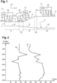
- FIG. 1 schematically illustrates a wall 1 of a tubular element whose profile must be reconstructed, for example to verify its conformity with regard to given specifications.
- This wall 1 has an external surface 2 and an internal surface 3 which jointly define a thickness of the wall 1 along a longitudinal axis X of the tubular element.
- the external surface 2 illustrated in the figure 1 present, successively from left to right of the figure 1 , a first portion 5 parallel to the longitudinal axis X, a second portion 6 having a positive angle ⁇ with the longitudinal axis X, and a third portion 7 parallel to the longitudinal axis X.
- the internal surface 3 illustrated on the figure 1 present, successively from left to right of the figure 1 , a first portion 8 parallel to the longitudinal axis X, a second portion 9 having a negative angle ⁇ with the longitudinal axis X, and a third portion 10 parallel to the longitudinal axis X.
- the first, second and third portions respectively 5, 6 and 7 for the external surface 2 and 8, 9 and 10 for the internal surface 3 do not have the same lengths along the longitudinal axis X.
- the wall 1 thus has, successively from left to right of the figure 1 , a first section 11, a second section 12, a third section 13, a fourth section 14 and a fifth section 15.
- the first section 11 has a thickness delimited by the first portion 5 of the external surface 2 and the first portion 8 of the internal surface 3.
- the second section 12 has a thickness delimited by the second portion 6 of the external surface 2 and the first portion 8 of the internal surface 3.
- the third section 13 has a thickness delimited by the second portion 6 of the external surface 2 and the second portion 9 of the internal surface 3.
- the fourth section 14 has a thickness delimited by the third portion 7 of the external surface 2 and the second portion 9 of the internal surface 3.
- the fifth section 15 has a thickness delimited by the third portion 7 of the external surface 2 and the third portion 10 of the internal surface 3.
- the external surface 2 and the internal surface 3 are parallel in the first section 11 and the fifth section 15.
- the thickness of the wall 1 is constant in the first section 11 and the fifth section 15.
- the external surface 2 and the internal surface 3 are not parallel in the second section 12, the third section 13 and the fourth section 14.
- the thickness of the wall 1 increases, due to the angles ⁇ and/or ⁇ , in the second section 12, the third section 13 and the fourth section 14.
- a sensor 16 also called a transducer, is used.
- This sensor 16 is, in the embodiment illustrated in the figure 1 , a multi-element sensor 16 mounted on a housing 17.
- the housing 17 has a face 18 on which the sensor 16 is mounted.
- the sensor 16 is configured to emit a plurality of ultrasonic shots with respective distinct orientations by means of delay laws, for example as described in the document WO200350527A1 . These delay laws allow the sensor 16 to carry out this plurality of ultrasonic shots according to an angular scan illustrated by the cone referenced 20 on the figure 1 . Such an angular scan represents for example a cone of 30° opening, for example 15° on either side of a straight line perpendicular to the face 18 of the housing 17 and passing through the emission point of the sensor 16.
- the housing 17 has two arms 19 of identical and predetermined length projecting from the housing 17 from the face 18. These arms 19 develop perpendicularly to the face 18.
- the sensor 16 is arranged equidistant from the arms 19.
- a location device is also associated with the sensor 16 in order to know precisely the position of the sensor 16, longitudinally and radially, and therefore to know precisely the coordinates of the point of emission of the ultrasonic shots.
- this location device is a wire encoder (not shown) connected precisely to the sensor 16 at the same radial and longitudinal coordinates as the point of emission of the ultrasounds.
- Other location devices can however be used such as laser detectors or the like.
- the senor 16 is moved along the wall 1.
- the housing 17 is positioned with the face 18 facing the wall 1 so that the sensor 16 is able to emit ultrasonic waves from this face 18 towards the external surface 2 of the wall 1.
- the housing 17 is positioned so that the arms 19 rest on the external surface 2.
- the housing 17 is then moved along the longitudinal axis X while keeping the arms 19 in contact with the external surface 2.
- This contact maintained between the arms 19 and the external surface 2 causes the housing 17 to be more or less inclined relative to the longitudinal axis X depending on the slope of the external surface 2 at the support points between the arms 19 and the external surface 2, as illustrated for example in FIG. figure 1 by three distinct positions 21A, 21B and 21C of the housing 17.
- the point of emission of the ultrasonic shots by the sensor 16 corresponds to the point of rotation of the housing 17 when said housing 17 moves along the longitudinal axis X, the point of rotation being imposed by a pivot connection between the housing 17 and a cell (not shown) allowing the immersion control of the part to be carried out by the sensor 16.
- the senor 16 For the different positions along the wall 1, the sensor 16 performs an ultrasonic scan and the data resulting from the scans performed at these different positions are compiled to reconstruct the thickness profile of the wall 1.
- the sensor 16 emits a plurality of ultrasonic shots.
- Each ultrasonic shot is emitted towards the wall 1 according to a respective orientation by means of a delay law.
- a plurality of ultrasonic waves at respective angles are sent towards the wall 1 so as to form an angular scan 20 of ultrasonic waves.
- the figure 1 illustrates an angular scan 20A, 20B and 20C carried out respectively at each of the three distinct positions 21A, 21B and 21C.
- Such an angular scan 20 makes it possible to avoid changes in orientation of the sensor 16 relative to the external surface 2.
- this angular scan makes it possible to obtain an ultrasonic shot in an orientation perpendicular to the external surface 2 despite the rotation of the housing 17 during its movement along the external surface 2, for example due to the support of one of the arms 19 on the first portion 5 of the external surface 2 while the second arm 19 is supported on the second portion 6 of the external surface 2 as illustrated by the position 21B on the figure 1 .
- this angular scan also makes it possible to ensure that at least one shot will impact the internal surface 3 in an orientation perpendicular to said internal surface 3, despite the fact that the orientation of the sensor 16 is independent of the slope of the internal surface 3 as for example in the second, third and fourth sections 12, 13 and 14 of the wall 1 illustrated in the figure 1 .
- Each current position also corresponds to a listening time window during which the sensor 16 receives the ultrasonic waves.
- the sensor 16 thus receives ultrasonic waves resulting from the reflection of the different ultrasonic shots emitted at said current position on the wall 1.
- the ultrasonic waves received during this time window make it possible to generate, for each shot of the plurality of shots emitted for the current position, a respective A-Scan associated with the corresponding ultrasonic shot of the plurality of shots emitted at this current position.
- a plurality of A-Scans representative of the wall 1 are generated, each corresponding to a shot at a respective angle from the sensor 16.
- a single listening time window is used for all the ultrasonic shots taken for the current position of the sensor 16.
- An analysis of the ultrasonic waves received makes it possible to differentiate the ultrasonic waves received by the sensor 16 and to generate for each ultrasonic shot a respective A-Scan.
- the generation of the A-scans is carried out by remote electronics connected to the sensor 16.
- the A-Scan having a surface echo of greatest amplitude among the A-Scans generated for said current position of the sensor 16 is selected.
- Such a surface echo corresponds to the reception by the sensor 16 of an ultrasonic wave resulting from the reflection of the ultrasonic shot corresponding to the A-Scan by the external surface 2.
- This A-Scan having the greatest surface echo amplitude represents the ultrasonic shot emitted from the sensor 16 with an orientation perpendicular to the external surface 2.
- the figure 2 illustrates the set of surface echoes 26 of the A-Scans selected for the different successive positions of the sensor 16 along the longitudinal axis X.
- This surface flight time corresponds to the time elapsed between the emission of the ultrasonic shot corresponding to the selected A-Scan and the impact of this ultrasonic shot on the external surface 2.
- this flight time corresponds to the time elapsed between the emission of the ultrasonic shot corresponding to the selected A-Scan by the sensor 16 and the reception by said sensor 16 of the surface echo corresponding to this selected ultrasonic shot, all divided by two.
- This surface distance is calculated as a function of the surface flight time calculated previously, or directly measured on the A-Scan, as a function of the propagation medium between the sensor 16 and the external surface 2 and as a function of the propagation speed of the ultrasonic shot in said propagation medium.
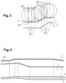
- FIG. 3 thus illustrates a plurality of surface circles 22 for a corresponding plurality of successive current positions.
- the outer surface 2 corresponds to the connection of the disjoint portions of the surface circles 22 thus drawn.
- the lower envelopes of these surface circles 22 which are not contiguous with other surface circles 22 represent the envelope of the outer surface 2.
- the junction of the portions of the surface circles 22 which are not located in other surface circles 22 represents the outer surface 2 of the wall 1.
- this selection of the A-Scan having the background echo of greatest amplitude makes it possible to overcome, on the one hand, the orientation of the sensor 16 relative to the longitudinal axis X and, on the other hand, the inclination of the internal surface 3 relative to the longitudinal axis X at the current position of the sensor 16.
- the figure 2 illustrated the set of bottom echoes 27 corresponding to the different A-Scans selected according to the position of the sensor, vertical axis, and time, horizontal axis.
- a background flight time is calculated. This background flight time corresponds to the time elapsed between the emission of the ultrasonic shot corresponding to the selected A-Scan by the sensor 16 and the reception by said sensor 16 of the background echo.
- a wall thickness is then calculated. This wall thickness is calculated as a function of the surface flight time, the background flight time, the propagation medium in wall 1 and the propagation speed of the ultrasonic shot in said propagation medium of wall 1.
- a difference between the background flight time and the surface flight time is calculated.
- This difference corresponds to the time elapsed between the impact of the ultrasonic shot on the external surface 2 and the impact on the external surface 2 of the ultrasonic wave reflected by the internal surface 3 and resulting from said ultrasonic shot.
- This difference represents the propagation time of an ultrasonic wave to make a round trip through the wall 1.
- the thickness of the wall crossed by the ultrasonic wave for the selected shot is then calculated by means of a part of this difference divided by two, to determine the propagation time of the ultrasonic wave corresponding to the selected ultrasonic shot to cross the wall 1, and, on the other hand, of the propagation medium in the wall 1 and the propagation speed of an ultrasonic wave in said propagation medium of the wall 1.
- the calculated wall thickness allows the reconstruction of the internal surface 3 by internal surface circles whose radius corresponds to the calculated thickness and whose center is located on the external surface 2 reconstructed previously.
- the impact point of the external surface of the ultrasonic shot corresponding to the selected A-Scan i.e. the A-Scan having the largest background echo, must be calculated.
- This impact point is calculated as a function of the surface echo of said selected A-Scan which makes it possible to obtain the distance traveled by the ultrasonic shot between the sensor 16 and the external surface 2, for example in a manner analogous to the calculation of the distance described above for the reconstruction of the external surface 2.
- the impact point of the ultrasonic shot corresponding to the selected A-Scan is then calculated as corresponding to the point of intersection between on the one hand a circle whose center is the emission point of the sensor 16 and the radius is said calculated traveled distance and, on the other hand, the external surface 2 whose profile was previously reconstructed.
- the selected A-Scan has a known angle of the shot from the sensor 16, so that it is possible to know which of the two possible potential impact points it corresponds to.
- the reconstruction of the internal surface 3 is carried out by connecting the disjoint portions, that is to say the portions which do not overlap, of the circles of internal surfaces calculated for the different successive positions of the sensor 16.
- all of the points of intersection are calculated between, on the one hand, a radial axis passing through the current position of the sensor 16 and, on the other hand, all of the circles of the internal surface calculated for the different positions of the sensor 16.
- the point of intersection closest to the longitudinal axis X, generally corresponding to the point furthest from the sensor 16, is then selected and corresponds to the position of the internal surface 3 for the current axial position of the sensor 16. All of the points of intersection selected for the different positions of the sensor 16 are then connected to form the profile of the internal surface 3.
- a reconstruction of the thickness profile of the wall 1 is obtained as shown for example in figure 4 which illustrates the thickness profile of wall 1 in the lower part of said figure 4 by comparison with the profile of wall 1 as reconstructed using the method described above in the upper part of said figure 4 .
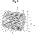
- This reconstruction in a section plane can be carried out all around the tubular element to obtain a three-dimensional image of the thickness profile of wall 1 of the tubular element as illustrated in the figure 5 .
- This thickness profile reconstruction method advantageously makes it possible to obtain a profile of the thickness of the wall 1 with a sensor 16 moving along the longitudinal axis X and whose orientation relative to said longitudinal axis X can vary during said movement, making the method easily industrializable.
- the fact that the point of rotation of the housing 17 and the point of emission of the sensor 16 are superimposed allows the sensor to rotate within the slope of the external surface 2 without affecting the result.
- the ultrasonic shots are used both to reconstruct the external surface 2 and the internal surface 3. This advantageously makes it possible, during a single movement of the housing 17 along the wall 1, to obtain all of the information making it possible to reconstruct the thickness profile of the wall 1.
- the method described above could be used to reconstruct the profile of the internal surface 3 only, for example by obtaining the profile of the external surface 2 according to another method and using the information on this profile of the external surface to calculate the profile of the internal surface 3 according to the method described above.
- the method is described above in the context of a housing 17 positioned in abutment on the external surface 2 of the tubular element.
- the housing could also be positioned in the tubular element, for example a tubular element of large internal diameter, to successively determine the profile of the internal wall 3 in a first step and the profile of the external wall 2 in a second step, that is to say in an order reverse to that described above when the housing 17 is in abutment on the external surface 2.
- Such a housing 17 positioned in the tubular element would then be held in abutment against the internal surface 3 with its face 18 presenting the sensor 16 facing the internal surface 3.
Landscapes
- Physics & Mathematics (AREA)
- General Physics & Mathematics (AREA)
- Health & Medical Sciences (AREA)
- Life Sciences & Earth Sciences (AREA)
- Chemical & Material Sciences (AREA)
- Analytical Chemistry (AREA)
- Biochemistry (AREA)
- General Health & Medical Sciences (AREA)
- Immunology (AREA)
- Pathology (AREA)
- Engineering & Computer Science (AREA)
- Signal Processing (AREA)
- Acoustics & Sound (AREA)
- Investigating Or Analyzing Materials By The Use Of Ultrasonic Waves (AREA)
- Length Measuring Devices Characterised By Use Of Acoustic Means (AREA)
Claims (12)
- Verfahren zur Rekonstruktion eines Dickenprofils eines zu kontrollierenden Bauteils, wobei das zu kontrollierende Bauteil eine erste Fläche (2) und eine zweite Fläche (3) aufweist, wobei das Verfahren für eine Vielzahl unterschiedlicher Emissionspunkte die Schritte aufweist:- für einen aktuellen Emissionspunkt der Vielzahl unterschiedlicher Emissionspunkte, Emission ausgehend von einem Wandler einer Vielzahl von Ultraschallschüssen in Richtung der ersten Fläche (2) des zu kontrollierenden Bauteils,- Empfang von Ultraschallwellen durch den Wandler während eines Zeitfensters,- Erzeugen einer Vielzahl von Bodenechosignalen, wobei jedes Bodenechosignal einem Ultraschallschuss zugeordnet ist, wobei jedes Bodenechosignal einer von der zweiten Fläche (3) des zu kontrollierenden Bauteils reflektierten und vom Wandler empfangenen Ultraschallwelle entspricht,- Auswahl eines Schusses unter der Vielzahl von Schüssen, wobei der ausgewählte Schuss das Bodenechosignal größter Amplitude unter den Bodenechosignalen aufweist,- Berechnen für den ausgewählten Schuss einer Bodenflugzeit entsprechend der Zeitspanne zwischen dem Übertragungszeitpunkt des ausgewählten Schusses von außen nach innen des zu kontrollierenden Bauteils und einem Kontaktzeitpunkt des ausgewählten Schusses mit der zweiten Fläche (3) des zu kontrollierenden Bauteils,- Berechnen der Koordinaten eines Flächenkontaktpunkts für den ausgewählten Schuss, wobei die Koordinaten eine axiale Koordinate entlang einer Längsachse (X) des zu kontrollierenden Bauteils und eine radiale Koordinate entlang einer radialen Achse lotrecht zur Längsachse (X) des zu kontrollierenden Bauteils aufweisen, wobei der Flächenkontaktpunkt dem Aufprallpunkt des ausgewählten Schusses auf die erste Fläche (2) des zu kontrollierenden Bauteils entspricht,- Berechnen einer Einheit potenzieller Positionen der zweiten Fläche (3) des zu kontrollierenden Bauteils abhängig von der Bodenflugzeit, den Koordinaten des Flächenkontaktpunkts und einem Ausbreitungsmilieu im zu kontrollierenden Bauteil,wobei das Verfahren außerdem den Schritt der Berechnung des Profils der zweiten Fläche (3) des zu kontrollierenden Bauteils durch Verbindung von getrennten Abschnitten der Einheiten potenzieller Positionen der zweiten Fläche (3) aufweist, die für die Vielzahl unterschiedlicher Emissionspunkte berechnet werden.
- Rekonstruktionsverfahren des Dickenprofils eines zu kontrollierenden Bauteils nach Anspruch 1, wobei die Einheit der potenziellen Positionen der zweiten Fläche (3) durchgehend ist, um einen Kreis zu formen, wobei die Verbindung der Einheiten der Positionen die Verbindung der getrennten Abschnitte der Kreise aufweist.
- Rekonstruktionsverfahren des Dickenprofils eines zu kontrollierenden Bauteils nach Anspruch 1 oder 2, das außerdem für die Vielzahl unterschiedlicher Emissionspunkte die Schritte aufweist:- Berechnen der Bodenschnittpunkte zwischen einer radial ausgerichteten und durch den Emissionspunkt verlaufenden Geraden und den Einheiten potenzieller Positionen der zweiten Fläche, berechnet für die verschiedenen Emissionspunkte der Vielzahl unterschiedlicher Emissionspunkte,- Auswahl eines Bodenschnittpunkts unter den berechneten Bodenschnittpunkten, wobei der ausgewählte Bodenschnittpunkt der der Längsachse des zu kontrollierenden Bauteils am nächsten liegende unter den berechneten Bodenschnittpunkten ist, wobei der ausgewählte Schnittpunkt dem Punkt der zweiten Fläche des zu kontrollierenden Bauteils im Bereich einer radial ausgerichteten, durch den Emissionspunkt verlaufenden Geraden entspricht,die Verbindung der Einheiten der potenziellen Positionen der zweiten Fläche weist die Verbindung der ausgewählten Bodenschnittpunkte auf.
- Rekonstruktionsverfahren des Dickenprofils eines zu kontrollierenden Bauteils nach einem der vorhergehenden Ansprüche, wobei der ausgewählte Schuss ein erster ausgewählter Schuss ist, das Verfahren weist außerdem für jeden Schuss der Vielzahl von Schüssen des aktuellen Emissionspunkts die Schritte auf:- Erzeugen einer Vielzahl von Schnittstellenechosignalen, wobei jedes Schnittstellenechosignal einem Ultraschallschuss der Vielzahl von Schüssen zugeordnet ist, wobei jedes Schnittstellenechosignal einer von der ersten Fläche des zu kontrollierenden Bauteils reflektierten und vom entsprechenden Wandler empfangenen Ultraschallwelle entspricht,- Auswahl eines zweiten Schusses unter der Vielzahl von Schüssen, wobei der zweite ausgewählte Schuss das Schnittstellenechosignal größter Amplitude unter den Schnittstellenechosignalen aufweist,- Berechnen für den ausgewählten zweiten Schuss einer Schnittstellenflugzeit entsprechend der Zeitspanne zwischen dem Emissionszeitpunkt des ausgewählten zweiten Schusses und einem Kontaktzeitpunkt des ausgewählten zweiten Schusses mit der ersten Fläche (2) des zu kontrollierenden Bauteils,- Berechnen einer Einheit potenzieller Positionen (22) der ersten Fläche (2) des zu kontrollierenden Bauteils abhängig von der Schnittstellenflugzeit, den Koordinaten des aktuellen Emissionspunkts und einem Ausbreitungsmilieu zwischen dem aktuellen Emissionspunkt und dem zu kontrollierende Bauteil, wobei das Verfahren außerdem den Schritt der Berechnung des Profils der ersten Fläche des zu kontrollierenden Bauteils durch Verbindung von getrennten Abschnitten der Einheiten potenzieller Positionen (22) der ersten Fläche (2) aufweist, die für die Vielzahl unterschiedlicher Emissionspunkte berechnet werden.
- Rekonstruktionsverfahren des Dickenprofils eines zu kontrollierenden Bauteils nach einem der vorhergehenden Ansprüche, wobei der Schritt der Emission einer Vielzahl von Ultraschallschüssen mittels eines Sensors (16) realisiert wird, wobei das Verfahren einen Schritt der Verschiebung des Sensors in Längs- und Radialrichtung aufweist.
- Rekonstruktionsverfahren des Dickenprofils eines zu kontrollierenden Bauteils nach Anspruch 5, wobei der Sensor (16) auf ein Gehäuse (17) montiert ist, wobei das Gehäuse (17) Auflagepunkte aufweist, die während der Verschiebung des Sensors (16) mit der ersten Fläche (2) des zu kontrollierenden Bauteils in Kontakt gehalten werden, wobei der Sensor (16) so auf das Gehäuse (17) zentriert ist, dass die vom Sensor (16) während der Emissionsschritte von Ultraschallschüssen emittierten Ultraschallschüsse ausgehend vom Rotationszentrum des Gehäuses (17) in einem konstanten Abstand von der ersten Fläche (2) des Bauteils emittiert werden.
- Rekonstruktionsverfahren des Dickenprofils eines zu kontrollierenden Bauteils nach Anspruch 6, wobei die ausgehend von einem Emissionspunkt emittierten Ultraschallschüsse gemäß einer Winkelabtastung zwischen 0° und 30° zu beiden Seiten einer Geraden lotrecht zu einer Seite (18) des Gehäuses (17), auf die der Sensor (16) montiert ist und die durch den Emissionspunkt des Sensors verläuft, emittiert werden.
- Rekonstruktionsverfahren des Dickenprofils eines zu kontrollierenden Bauteils nach einem der vorhergehenden Ansprüche, wobei das Bauteil ein Bauteil komplexer Form ist, das Variationen eines Innendurchmessers und/oder eines Außendurchmessers des Bauteils entlang der Längsachse des Bauteils aufweist.
- Rekonstruktionsverfahren des Dickenprofils eines zu kontrollierenden Bauteils nach einem der vorhergehenden Ansprüche, das außerdem einen Schritt der Anwendung eines Verzögerungsgesetzes für einen jeweiligen Schuss der Vielzahl von emittierten Schüssen aufweist, die für den aktuellen Emissionspunkt der Vielzahl von Ultraschallschüssen emittiert werden.
- Rekonstruktionsverfahren des Dickenprofils eines zu kontrollierenden Bauteils nach einem der vorhergehenden Ansprüche, das außerdem die Schritte der Bestimmung der Koordinaten des Emissionspunkts der Vielzahl von Schüssen aufweist.
- Rekonstruktionsverfahren des Dickenprofils eines zu kontrollierenden Bauteils nach Anspruch 10, wobei die Bestimmung der Koordinaten des Emissionspunkts mittels eines Drahtcodierers durchgeführt wird.
- Rekonstruktionsverfahren des Dickenprofils eines zu kontrollierenden Bauteils nach einem der vorhergehenden Ansprüche, das außerdem die Korrekturschritte der berechneten Flugzeiten aufweist.
Applications Claiming Priority (2)
| Application Number | Priority Date | Filing Date | Title |
|---|---|---|---|
| FR2108669A FR3126156B1 (fr) | 2021-08-12 | 2021-08-12 | Procédé de reconstruction d’un profil d’épaisseur de pièce à contrôler |
| PCT/EP2022/072421 WO2023017070A1 (fr) | 2021-08-12 | 2022-08-10 | Procédé de reconstruction d'un profil d'épaisseur de pièce à controler |
Publications (2)
| Publication Number | Publication Date |
|---|---|
| EP4384775A1 EP4384775A1 (de) | 2024-06-19 |
| EP4384775B1 true EP4384775B1 (de) | 2025-02-19 |
Family
ID=78536333
Family Applications (1)
| Application Number | Title | Priority Date | Filing Date |
|---|---|---|---|
| EP22761241.3A Active EP4384775B1 (de) | 2021-08-12 | 2022-08-10 | Methode zur rekonstruktion eines dickenprofils eines zu inspizierenden objekts |
Country Status (7)
| Country | Link |
|---|---|
| US (1) | US20240353375A1 (de) |
| EP (1) | EP4384775B1 (de) |
| CN (1) | CN117836586A (de) |
| CA (1) | CA3228651A1 (de) |
| FR (1) | FR3126156B1 (de) |
| PL (1) | PL4384775T3 (de) |
| WO (1) | WO2023017070A1 (de) |
Families Citing this family (1)
| Publication number | Priority date | Publication date | Assignee | Title |
|---|---|---|---|---|
| WO2025194250A1 (en) * | 2024-03-18 | 2025-09-25 | Evident Canada, Inc. | Acoustic non-destructive corrosion mapping |
Family Cites Families (5)
| Publication number | Priority date | Publication date | Assignee | Title |
|---|---|---|---|---|
| FR2833706B1 (fr) | 2001-12-13 | 2004-07-23 | Setval | Controle non destructif a capteurs ultrasonores, de produits de metallurgie |
| US6522288B1 (en) * | 2002-01-09 | 2003-02-18 | M/A-Com, Inc. | Method and apparatus for determining location of objects based on range readings from multiple sensors |
| US7823454B2 (en) * | 2006-11-29 | 2010-11-02 | Babcock & Wilcox Technical Services Group, Inc. | Ultrasonic inspection method |
| JP5565904B2 (ja) * | 2010-05-24 | 2014-08-06 | 一般財団法人電力中央研究所 | 超音波探傷試験体の表面形状の同定方法並びに同定プログラム、開口合成処理プログラム及びフェーズドアレイ探傷プログラム |
| DE102018119206B4 (de) * | 2018-08-07 | 2024-08-08 | Salzgitter Mannesmann Forschung Gmbh | Verfahren zum Erfassen einer Geometrie eines Bereichs eines Gegenstandes mittels Ultraschall |
-
2021
- 2021-08-12 FR FR2108669A patent/FR3126156B1/fr active Active
-
2022
- 2022-08-10 CN CN202280056331.XA patent/CN117836586A/zh active Pending
- 2022-08-10 PL PL22761241.3T patent/PL4384775T3/pl unknown
- 2022-08-10 EP EP22761241.3A patent/EP4384775B1/de active Active
- 2022-08-10 US US18/682,537 patent/US20240353375A1/en active Pending
- 2022-08-10 CA CA3228651A patent/CA3228651A1/en active Pending
- 2022-08-10 WO PCT/EP2022/072421 patent/WO2023017070A1/fr not_active Ceased
Also Published As
| Publication number | Publication date |
|---|---|
| FR3126156B1 (fr) | 2024-03-29 |
| CA3228651A1 (en) | 2023-02-16 |
| CN117836586A (zh) | 2024-04-05 |
| WO2023017070A1 (fr) | 2023-02-16 |
| FR3126156A1 (fr) | 2023-02-17 |
| US20240353375A1 (en) | 2024-10-24 |
| EP4384775A1 (de) | 2024-06-19 |
| PL4384775T3 (pl) | 2025-05-19 |
Similar Documents
| Publication | Publication Date | Title |
|---|---|---|
| EP1899721B1 (de) | Verfahren und vorrichtung zur überprüfung einer rohrschweissverbindung mittels einer ultraschallsonde | |
| EP0461018B2 (de) | Verfahren und Vorrichtung zur Kontrolle der Dicke und der Kohäsion der Verbindung eines Duplexrohrs | |
| FR3003646A1 (fr) | Dispositif et procede de controle non destructif de produits tubulaires, notamment sur site | |
| EP2577224B1 (de) | Produktionssteuerungsverfahren und vorrichtung zur überprüfung der traversierbarkeit von rohren | |
| FR3031186A1 (fr) | Procede de controle d'une ligne flexible et installation associee | |
| EP3642609B1 (de) | Vorrichtung und verfahren zur zerstörungsfreien prüfung eines rohrförmigen produkts mit einer komplexen form | |
| CA3108506C (fr) | Dispositif d'examen de l'interieur d'une conduite par ultrason multi-element | |
| EP4384775B1 (de) | Methode zur rekonstruktion eines dickenprofils eines zu inspizierenden objekts | |
| CA3039923A1 (fr) | Procede d'inspection automatique d'un cordon de soudure depose dans un chanfrein forme entre deux pieces metalliques a assembler | |
| EP1891428A1 (de) | Verfahren zur inspektion des zustands einer antriebswelle einer rotationsmaschine | |
| EP0099816B1 (de) | Verfahren und Vorrichtung für Ultraschall Echographie | |
| EP4095527B1 (de) | Verfahren und system zur ultraschalldetektion von internen defekten eines bauteils, insbesondere für ein luftfahrzeug | |
| EP2381251B1 (de) | Vorrichtung und Verfahren zur zerstörungsfreien Erkennung von Dicke-Anomalien einer Rohrwand | |
| EP4630802A1 (de) | Verfahren zur erkennung von rissen in einem rohrförmigen rohr | |
| EP3289348B1 (de) | Verfahren zur steuerung von verschweissungen mittels ultraschall | |
| EP2166306B1 (de) | Vorrichtung und Verfahren zum Prüfen von Abmessungen einer Kernbrennstoffhülle eines Kernreaktorsteuerstabbündels | |
| EP4078165A1 (de) | Verfahren zum charakterisieren der inhaltlichkeit eines objekts, das einem mechanischen, thermischen oder thermoelastischen stress ausgesetzt ist, der in dem objekt elastische wellen erzeugen kann | |
| FR2907901A1 (fr) | Procede de controle non destructif par ultrasons et sonde de mesure pour la mise en oeuvre du procede | |
| WO2026002920A1 (fr) | Procédé et ensemble d'inspection par ultrasons d'une tuyauterie | |
| OA19058A (fr) | Procédé d'inspection automatique d'un cordon de soudure déposé dans un chanfrein formé entre deux pièces métalliques à assembler. |
Legal Events
| Date | Code | Title | Description |
|---|---|---|---|
| STAA | Information on the status of an ep patent application or granted ep patent |
Free format text: STATUS: UNKNOWN |
|
| STAA | Information on the status of an ep patent application or granted ep patent |
Free format text: STATUS: THE INTERNATIONAL PUBLICATION HAS BEEN MADE |
|
| PUAI | Public reference made under article 153(3) epc to a published international application that has entered the european phase |
Free format text: ORIGINAL CODE: 0009012 |
|
| STAA | Information on the status of an ep patent application or granted ep patent |
Free format text: STATUS: REQUEST FOR EXAMINATION WAS MADE |
|
| 17P | Request for examination filed |
Effective date: 20240206 |
|
| AK | Designated contracting states |
Kind code of ref document: A1 Designated state(s): AL AT BE BG CH CY CZ DE DK EE ES FI FR GB GR HR HU IE IS IT LI LT LU LV MC MK MT NL NO PL PT RO RS SE SI SK SM TR |
|
| GRAP | Despatch of communication of intention to grant a patent |
Free format text: ORIGINAL CODE: EPIDOSNIGR1 |
|
| STAA | Information on the status of an ep patent application or granted ep patent |
Free format text: STATUS: GRANT OF PATENT IS INTENDED |
|
| DAV | Request for validation of the european patent (deleted) | ||
| DAX | Request for extension of the european patent (deleted) | ||
| INTG | Intention to grant announced |
Effective date: 20240930 |
|
| GRAS | Grant fee paid |
Free format text: ORIGINAL CODE: EPIDOSNIGR3 |
|
| GRAA | (expected) grant |
Free format text: ORIGINAL CODE: 0009210 |
|
| STAA | Information on the status of an ep patent application or granted ep patent |
Free format text: STATUS: THE PATENT HAS BEEN GRANTED |
|
| AK | Designated contracting states |
Kind code of ref document: B1 Designated state(s): AL AT BE BG CH CY CZ DE DK EE ES FI FR GB GR HR HU IE IS IT LI LT LU LV MC MK MT NL NO PL PT RO RS SE SI SK SM TR |
|
| REG | Reference to a national code |
Ref country code: GB Ref legal event code: FG4D Free format text: NOT ENGLISH |
|
| REG | Reference to a national code |
Ref country code: CH Ref legal event code: EP |
|
| REG | Reference to a national code |
Ref country code: DE Ref legal event code: R096 Ref document number: 602022010917 Country of ref document: DE |
|
| REG | Reference to a national code |
Ref country code: IE Ref legal event code: FG4D Free format text: LANGUAGE OF EP DOCUMENT: FRENCH |
|
| REG | Reference to a national code |
Ref country code: NL Ref legal event code: MP Effective date: 20250219 |
|
| PG25 | Lapsed in a contracting state [announced via postgrant information from national office to epo] |
Ref country code: RS Free format text: LAPSE BECAUSE OF FAILURE TO SUBMIT A TRANSLATION OF THE DESCRIPTION OR TO PAY THE FEE WITHIN THE PRESCRIBED TIME-LIMIT Effective date: 20250519 |
|
| PG25 | Lapsed in a contracting state [announced via postgrant information from national office to epo] |
Ref country code: FI Free format text: LAPSE BECAUSE OF FAILURE TO SUBMIT A TRANSLATION OF THE DESCRIPTION OR TO PAY THE FEE WITHIN THE PRESCRIBED TIME-LIMIT Effective date: 20250219 |
|
| PG25 | Lapsed in a contracting state [announced via postgrant information from national office to epo] |
Ref country code: ES Free format text: LAPSE BECAUSE OF FAILURE TO SUBMIT A TRANSLATION OF THE DESCRIPTION OR TO PAY THE FEE WITHIN THE PRESCRIBED TIME-LIMIT Effective date: 20250219 |
|
| REG | Reference to a national code |
Ref country code: LT Ref legal event code: MG9D |
|
| PG25 | Lapsed in a contracting state [announced via postgrant information from national office to epo] |
Ref country code: IS Free format text: LAPSE BECAUSE OF FAILURE TO SUBMIT A TRANSLATION OF THE DESCRIPTION OR TO PAY THE FEE WITHIN THE PRESCRIBED TIME-LIMIT Effective date: 20250619 |
|
| PG25 | Lapsed in a contracting state [announced via postgrant information from national office to epo] |
Ref country code: NL Free format text: LAPSE BECAUSE OF FAILURE TO SUBMIT A TRANSLATION OF THE DESCRIPTION OR TO PAY THE FEE WITHIN THE PRESCRIBED TIME-LIMIT Effective date: 20250219 |
|
| PG25 | Lapsed in a contracting state [announced via postgrant information from national office to epo] |
Ref country code: HR Free format text: LAPSE BECAUSE OF FAILURE TO SUBMIT A TRANSLATION OF THE DESCRIPTION OR TO PAY THE FEE WITHIN THE PRESCRIBED TIME-LIMIT Effective date: 20250219 |
|
| PG25 | Lapsed in a contracting state [announced via postgrant information from national office to epo] |
Ref country code: PT Free format text: LAPSE BECAUSE OF FAILURE TO SUBMIT A TRANSLATION OF THE DESCRIPTION OR TO PAY THE FEE WITHIN THE PRESCRIBED TIME-LIMIT Effective date: 20250620 Ref country code: LV Free format text: LAPSE BECAUSE OF FAILURE TO SUBMIT A TRANSLATION OF THE DESCRIPTION OR TO PAY THE FEE WITHIN THE PRESCRIBED TIME-LIMIT Effective date: 20250219 |
|
| PG25 | Lapsed in a contracting state [announced via postgrant information from national office to epo] |
Ref country code: GR Free format text: LAPSE BECAUSE OF FAILURE TO SUBMIT A TRANSLATION OF THE DESCRIPTION OR TO PAY THE FEE WITHIN THE PRESCRIBED TIME-LIMIT Effective date: 20250520 Ref country code: BG Free format text: LAPSE BECAUSE OF FAILURE TO SUBMIT A TRANSLATION OF THE DESCRIPTION OR TO PAY THE FEE WITHIN THE PRESCRIBED TIME-LIMIT Effective date: 20250219 |
|
| PG25 | Lapsed in a contracting state [announced via postgrant information from national office to epo] |
Ref country code: SE Free format text: LAPSE BECAUSE OF FAILURE TO SUBMIT A TRANSLATION OF THE DESCRIPTION OR TO PAY THE FEE WITHIN THE PRESCRIBED TIME-LIMIT Effective date: 20250219 |
|
| PG25 | Lapsed in a contracting state [announced via postgrant information from national office to epo] |
Ref country code: SM Free format text: LAPSE BECAUSE OF FAILURE TO SUBMIT A TRANSLATION OF THE DESCRIPTION OR TO PAY THE FEE WITHIN THE PRESCRIBED TIME-LIMIT Effective date: 20250219 |
|
| PG25 | Lapsed in a contracting state [announced via postgrant information from national office to epo] |
Ref country code: DK Free format text: LAPSE BECAUSE OF FAILURE TO SUBMIT A TRANSLATION OF THE DESCRIPTION OR TO PAY THE FEE WITHIN THE PRESCRIBED TIME-LIMIT Effective date: 20250219 |
|
| PGFP | Annual fee paid to national office [announced via postgrant information from national office to epo] |
Ref country code: DE Payment date: 20250724 Year of fee payment: 4 |
|
| PGFP | Annual fee paid to national office [announced via postgrant information from national office to epo] |
Ref country code: NO Payment date: 20250725 Year of fee payment: 4 |
|
| PG25 | Lapsed in a contracting state [announced via postgrant information from national office to epo] |
Ref country code: IT Free format text: LAPSE BECAUSE OF FAILURE TO SUBMIT A TRANSLATION OF THE DESCRIPTION OR TO PAY THE FEE WITHIN THE PRESCRIBED TIME-LIMIT Effective date: 20250219 |
|
| PGFP | Annual fee paid to national office [announced via postgrant information from national office to epo] |
Ref country code: PL Payment date: 20250724 Year of fee payment: 4 |
|
| PG25 | Lapsed in a contracting state [announced via postgrant information from national office to epo] |
Ref country code: AT Free format text: LAPSE BECAUSE OF FAILURE TO SUBMIT A TRANSLATION OF THE DESCRIPTION OR TO PAY THE FEE WITHIN THE PRESCRIBED TIME-LIMIT Effective date: 20250219 |
|
| PG25 | Lapsed in a contracting state [announced via postgrant information from national office to epo] |
Ref country code: CZ Free format text: LAPSE BECAUSE OF FAILURE TO SUBMIT A TRANSLATION OF THE DESCRIPTION OR TO PAY THE FEE WITHIN THE PRESCRIBED TIME-LIMIT Effective date: 20250219 Ref country code: EE Free format text: LAPSE BECAUSE OF FAILURE TO SUBMIT A TRANSLATION OF THE DESCRIPTION OR TO PAY THE FEE WITHIN THE PRESCRIBED TIME-LIMIT Effective date: 20250219 |
|
| PG25 | Lapsed in a contracting state [announced via postgrant information from national office to epo] |
Ref country code: RO Free format text: LAPSE BECAUSE OF FAILURE TO SUBMIT A TRANSLATION OF THE DESCRIPTION OR TO PAY THE FEE WITHIN THE PRESCRIBED TIME-LIMIT Effective date: 20250219 |
|
| PG25 | Lapsed in a contracting state [announced via postgrant information from national office to epo] |
Ref country code: SK Free format text: LAPSE BECAUSE OF FAILURE TO SUBMIT A TRANSLATION OF THE DESCRIPTION OR TO PAY THE FEE WITHIN THE PRESCRIBED TIME-LIMIT Effective date: 20250219 |
|
| REG | Reference to a national code |
Ref country code: DE Ref legal event code: R097 Ref document number: 602022010917 Country of ref document: DE |
|
| PLBE | No opposition filed within time limit |
Free format text: ORIGINAL CODE: 0009261 |
|
| STAA | Information on the status of an ep patent application or granted ep patent |
Free format text: STATUS: NO OPPOSITION FILED WITHIN TIME LIMIT |
|
| REG | Reference to a national code |
Ref country code: CH Ref legal event code: L10 Free format text: ST27 STATUS EVENT CODE: U-0-0-L10-L00 (AS PROVIDED BY THE NATIONAL OFFICE) Effective date: 20251231 |
|
| PGFP | Annual fee paid to national office [announced via postgrant information from national office to epo] |
Ref country code: FR Payment date: 20251119 Year of fee payment: 4 |
|
| 26N | No opposition filed |
Effective date: 20251120 |
|
| REG | Reference to a national code |
Ref country code: CH Ref legal event code: H13 Free format text: ST27 STATUS EVENT CODE: U-0-0-H10-H13 (AS PROVIDED BY THE NATIONAL OFFICE) Effective date: 20260324 |
|
| PG25 | Lapsed in a contracting state [announced via postgrant information from national office to epo] |
Ref country code: MC Free format text: LAPSE BECAUSE OF FAILURE TO SUBMIT A TRANSLATION OF THE DESCRIPTION OR TO PAY THE FEE WITHIN THE PRESCRIBED TIME-LIMIT Effective date: 20250219 |
|
| PG25 | Lapsed in a contracting state [announced via postgrant information from national office to epo] |
Ref country code: LU Free format text: LAPSE BECAUSE OF NON-PAYMENT OF DUE FEES Effective date: 20250810 |