EP4189329B1 - Sichtbasierte positions- und wendemarkervorhersage - Google Patents
Sichtbasierte positions- und wendemarkervorhersage Download PDFInfo
- Publication number
- EP4189329B1 EP4189329B1 EP20776249.3A EP20776249A EP4189329B1 EP 4189329 B1 EP4189329 B1 EP 4189329B1 EP 20776249 A EP20776249 A EP 20776249A EP 4189329 B1 EP4189329 B1 EP 4189329B1
- Authority
- EP
- European Patent Office
- Prior art keywords
- image
- vehicle
- images
- neural network
- coordinates
- Prior art date
- Legal status (The legal status is an assumption and is not a legal conclusion. Google has not performed a legal analysis and makes no representation as to the accuracy of the status listed.)
- Active
Links
Images




Classifications
-
- G—PHYSICS
- G01—MEASURING; TESTING
- G01C—MEASURING DISTANCES, LEVELS OR BEARINGS; SURVEYING; NAVIGATION; GYROSCOPIC INSTRUMENTS; PHOTOGRAMMETRY OR VIDEOGRAMMETRY
- G01C21/00—Navigation; Navigational instruments not provided for in groups G01C1/00 - G01C19/00
- G01C21/26—Navigation; Navigational instruments not provided for in groups G01C1/00 - G01C19/00 specially adapted for navigation in a road network
- G01C21/34—Route searching; Route guidance
- G01C21/36—Input/output arrangements for on-board computers
- G01C21/3602—Input other than that of destination using image analysis, e.g. detection of road signs, lanes, buildings, real preceding vehicles using a camera
-
- G—PHYSICS
- G01—MEASURING; TESTING
- G01C—MEASURING DISTANCES, LEVELS OR BEARINGS; SURVEYING; NAVIGATION; GYROSCOPIC INSTRUMENTS; PHOTOGRAMMETRY OR VIDEOGRAMMETRY
- G01C21/00—Navigation; Navigational instruments not provided for in groups G01C1/00 - G01C19/00
- G01C21/26—Navigation; Navigational instruments not provided for in groups G01C1/00 - G01C19/00 specially adapted for navigation in a road network
- G01C21/28—Navigation; Navigational instruments not provided for in groups G01C1/00 - G01C19/00 specially adapted for navigation in a road network with correlation of data from several navigational instruments
- G01C21/30—Map- or contour-matching
-
- G—PHYSICS
- G01—MEASURING; TESTING
- G01C—MEASURING DISTANCES, LEVELS OR BEARINGS; SURVEYING; NAVIGATION; GYROSCOPIC INSTRUMENTS; PHOTOGRAMMETRY OR VIDEOGRAMMETRY
- G01C21/00—Navigation; Navigational instruments not provided for in groups G01C1/00 - G01C19/00
- G01C21/10—Navigation; Navigational instruments not provided for in groups G01C1/00 - G01C19/00 by using measurements of speed or acceleration
- G01C21/12—Navigation; Navigational instruments not provided for in groups G01C1/00 - G01C19/00 by using measurements of speed or acceleration executed aboard the object being navigated; Dead reckoning
- G01C21/16—Navigation; Navigational instruments not provided for in groups G01C1/00 - G01C19/00 by using measurements of speed or acceleration executed aboard the object being navigated; Dead reckoning by integrating acceleration or speed, i.e. inertial navigation
- G01C21/165—Navigation; Navigational instruments not provided for in groups G01C1/00 - G01C19/00 by using measurements of speed or acceleration executed aboard the object being navigated; Dead reckoning by integrating acceleration or speed, i.e. inertial navigation combined with non-inertial navigation instruments
- G01C21/1656—Navigation; Navigational instruments not provided for in groups G01C1/00 - G01C19/00 by using measurements of speed or acceleration executed aboard the object being navigated; Dead reckoning by integrating acceleration or speed, i.e. inertial navigation combined with non-inertial navigation instruments with passive imaging devices, e.g. cameras
-
- G—PHYSICS
- G06—COMPUTING OR CALCULATING; COUNTING
- G06T—IMAGE DATA PROCESSING OR GENERATION, IN GENERAL
- G06T7/00—Image analysis
- G06T7/70—Determining position or orientation of objects or cameras
- G06T7/73—Determining position or orientation of objects or cameras using feature-based methods
- G06T7/74—Determining position or orientation of objects or cameras using feature-based methods involving reference images or patches
-
- G—PHYSICS
- G06—COMPUTING OR CALCULATING; COUNTING
- G06V—IMAGE OR VIDEO RECOGNITION OR UNDERSTANDING
- G06V20/00—Scenes; Scene-specific elements
- G06V20/50—Context or environment of the image
- G06V20/56—Context or environment of the image exterior to a vehicle by using sensors mounted on the vehicle
-
- G—PHYSICS
- G06—COMPUTING OR CALCULATING; COUNTING
- G06T—IMAGE DATA PROCESSING OR GENERATION, IN GENERAL
- G06T2207/00—Indexing scheme for image analysis or image enhancement
- G06T2207/20—Special algorithmic details
- G06T2207/20081—Training; Learning
-
- G—PHYSICS
- G06—COMPUTING OR CALCULATING; COUNTING
- G06T—IMAGE DATA PROCESSING OR GENERATION, IN GENERAL
- G06T2207/00—Indexing scheme for image analysis or image enhancement
- G06T2207/20—Special algorithmic details
- G06T2207/20084—Artificial neural networks [ANN]
-
- G—PHYSICS
- G06—COMPUTING OR CALCULATING; COUNTING
- G06T—IMAGE DATA PROCESSING OR GENERATION, IN GENERAL
- G06T2207/00—Indexing scheme for image analysis or image enhancement
- G06T2207/30—Subject of image; Context of image processing
- G06T2207/30248—Vehicle exterior or interior
- G06T2207/30252—Vehicle exterior; Vicinity of vehicle
Definitions
- the present disclosure relates to a computer-implemented method and an apparatus for determining a vehicle's position and predicting turn points and lane changes.
- GNSS Global Navigation Satellite Systems
- present navigation systems comprise dead reckoning processes which calculate the vehicle's position by using a previously determined position (by the GNSS) and estimating the present position based on an estimation of the vehicle's speed and course over elapsed time since the previous determined position.
- IMU Internal Measurement Unit
- US 2018/164812 A1 describes a training data generation method that includes acquiring an image captured from a vehicle and location information of the vehicle corresponding to the image; acquiring map data corresponding to the acquired location information; determining truth data including information associated with a road included in the image from the acquired map data; and generating training data including the image and the determined truth data.
- WO 2020/048623 A1 relates to a method for estimating a pose of a robot.
- a second vehicle mounted camera can be coupled to the logic and the computer-implemented method may be operable to instruct the second vehicle mounted camera to capture a further plurality of images and transmit those to the logic to more accurately determine the vehicle's position and heading vector in real time.
- the first and/or the second vehicle mounted cameras can be forward-facing cameras (FFC) placed to capture images of the view directly in front of the vehicle.
- FFC forward-facing cameras
- the logic may be operable to collect, as a first training data subset, at least one image of the first plurality of images, obtain, as a second training data subset, image-related coordinates of navigation key points related to the at least one image of the first training data subset, supply the first training data subset and the second training data subset to an artificial neural network as a training dataset. train the artificial neural network on the training dataset to predict image-related coordinates of navigation key points indicative of road sign locations and/or turn points, and process the input dataset by the artificial neural network to predict image-related coordinates of navigation key points indicative of road sign locations and/or turn points.
- Fig. 1 shows an exemplary overall system architecture for vision-based location with augmented reality capabilities.
- the system architecture may be part of a vehicle's on-board navigation system, wherein the navigation system can predict navigation key points indicative of road sign locations and/or turn points. Some examples of turn points include, but are not limited to, lane changes and intersections.
- the navigation system can be implemented in any type of road-going vehicle, such as a car, lorry, bus, etc.
- the system may comprise a Car Positioning Block 102, which may calculate the position of the vehicle based on canonical Global Navigation Satellite System (GNSS) and/or Inertial Measurement Unit (IMU) sensors.
- the Car Positioning Block 102 may additionally derive the vehicle's position and heading vector from Visual Odometry (VO).
- VO is a real-time computer vision algorithm that computes the angular changes between one forward-facing camera (FFC) frame to the next frame. When this is added to other signals coming from the GNSS subsystem, IMU and vehicle speed, the vehicle's position and heading vector can be determined with a greater accuracy.
- the Car Positioning Block 102 will be described in more detail in Fig. 2 .
- the position and heading vector can then be used by the Aerial Imagery Marker Database 112, an offline database, to obtain suitable marker positions that have been extracted offline by an artificial neural network, wherein marker positions are equivalent to navigation key points indicative of road sign locations and/or turn points.
- the Aerial Imagery Marker Database 112 may be built by scanning satellite and/or aerial images of the earth's surface. That Database 112 may further comprise a marker selector (not shown) which uses current car's location and route information to select markers (for example road sign locations and/or turn points) related to the vehicle's current route.
- the building of the offline Aerial Imagery Marker Database 112 will be discussed in more detail in Figs. 3 to 5 .
- the position and heading vector can additionally be used by the Scene Understanding 104 block to better determine marker locations within an FFC frame.
- Scene Understanding 104 is a neural network that can run in real-time to place a marker (for example road sign locations and/or turn points) relative to the scene coming from the vehicle's forward-facing camera (FFC) or similar camera using semantical image analysis.
- Scene Understanding 104 may scan FFC frames und use scene analysis and other sources of information (for example standard-definition maps) to determine screen coordinates of the marker locations as well as depth information and/or ground plane estimation of the marker locations.
- Scene Understanding 104 will be discussed in more detail in Figs. 6 to 9 .
- Scene Understanding 104 and the offline extracted marker positions from the Aerial Imagery Marker Database 112 can be used separate or together to calculate the actual marker position relying on different marker position sources and predictions. Therefore, the system architecture (i.e. the vehicle's navigation system) can accurately predict an upcoming road sign and/or turn point using any one of the predicted marker positions of the Aerial Imagery Marker Database 112, the vehicle's FFC frames from Scene Understanding 104, or a combination of the two.
- the Marker Positioning 106 block can use information and normalized confidence scores from the Aerial Imagery Marker Database 112 and Scene Understanding 104 components to determine where to place the marker based on the vehicle's position and heading vector.
- the Marker Positioning 106 block may implement smoothing techniques to avoid jitter caused by changing which source to use for each marker for a given route.
- the Marker Rendering Engine 114 may work in synchrony with Scene Understanding 104 and/or the Aerial Imagery Marker Database 112 to translate the marker's geo-coordinates into screen coordinates, such that the markers can be displayed on the vehicle's navigation screen and are visible to the user.
- Route Planning 108, 110 can then determine the waypoints and maneuvers that the vehicle is expected to follow from the origin to the desired destination.
- Fig. 2 shows a more detailed example of the Car Positioning Block 102 of Fig. 1 , which may be an apparatus for determining a vehicle's position, such as part of the vehicle's navigation system.
- the apparatus may comprise a first vehicle mounted camera, such as a forward-facing camera (FFC) 202 which captures a plurality of forward-facing (relative to the vehicle) images.
- the FFC 202 may be coupled to a Visual Odometry (VO) unit 204 which can instruct the FFC 202 to capture the plurality of forward-facing images, and subsequently receives the first plurality of images from the FFC 202.
- the plurality of images may be taken sequentially with equidistant time periods between each image.
- the VO unit 204 can compute the angular changes between one image and the next image (one frame to the next frame). Subsequently, the VO unit 204 can determine the vehicle's position and heading vector in real-time from the determined angular changes and transmit the vehicle's position and heading vector to the Fusion Engine 210.
- the Fusion Engine 210 may receive additional measurements, such as GPS coordinates from a Global Navigation Satellite System (GNSS) module 208, Inertial Measurement Unit (IMU) measurements from an IMU module 206, and the vehicle's velocity.
- GNSS Global Navigation Satellite System
- IMU Inertial Measurement Unit
- the GNSS module 208, IMU module 206 and VO unit 204 may each be coupled to the Fusion Engine 210 by physical or wireless means such that they can transmit signals to each other.
- the FFC 202 (and any further camera) may be coupled to the VO unit 204 by physical or wireless means.
- the vehicle's velocity may be recorded from the vehicle's speedometer or from an external source, such as by calculation from the GNSS module 208.
- the Fusion Engine 210 can compare the vehicle's position and heading vector calculated from the images captured by the FFC 202 to the measurements received from the GNSS module 208, IMU module 206 and vehicle speed to determine a confidence value of the calculated vehicle position and heading vector. If the confidence value is determined to be below a pre-determined threshold, the Fusion Engine 210 may instruct the FFC 202 (through the VO unit 204) to increase the frequency at which images are captured, such that the FFC 202 captures a further plurality of sequential images with a reduced time period between each image.
- the VO unit 204 can receive the further plurality of images taken at an increased frequency, and can compute the angular changes between one image and the next image (one frame to the next frame) to determine an updated version of the vehicle's position and heading vector in real-time, to be transmitted to the Fusion Engine 210.
- the Fusion Engine 210 may repeat this method if the confidence value is still determined to be below the pre-determined threshold.
- the VO unit 204 can calculate an adequate angle to overcome the drift and noisiness of a typical IMU.
- a stereo-vision may be implemented comprising the first vehicle mounted camera and a second vehicle mounted camera (for example two FFCs), thus allowing for the VO unit 204 to compute an even more precise angle as well as provide depth information. It should be noted that any number of vehicle mounted cameras or FFCs can be used to provide more accurate results.
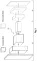
- Fig. 3 shows an example of a deep neural network, a type of artificial neural network, of the present disclosure.
- the deep neural network may be a convolutional neural network 302 that may be trained and, after training, stored in an apparatus 300 of the present disclosure.
- the convolutional neural network 302 may comprise a multitude of convolution blocks 304, a multitude of deconvolution blocks 306 and an output layer (not shown). Each block may comprise several layers.
- the training dataset is supplied to the first one of the convolution blocks 304.
- the input dataset i.e. the defined region of interest
- the convolution blocks 304 and the deconvolution blocks 306 may be two-dimensional.
- the deconvolution blocks 306 followed by the output layer may transform the final output data of the convolution blocks 304 into the output dataset (output predictions) that is then output by the output layer.
- the output dataset includes the predicted key point marker locations, i.e., the predicted virtual road sign locations.
- the output dataset of the convolutional neural network 302 may be given by a pixel map of possible intersections in the pre-determined region (training phase) or in the defined region of interest (inference phase) with a probability value (probability score) associated with each pixel. Those pixels for which the probability score is high, i.e., exceeds a predefined threshold (for example, 90% (0.9)), are then identified as predicted key point marker locations.
- a predefined threshold for example, 90% (0.9
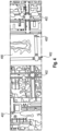
- Fig. 4 shows an example of key point marker locations 402 that have been predicted by the deep neural network of the present disclosure in a region of interest 400 which was supplied to the trained deep neural network as input data during inference.
- the predicted key point marker locations 402 represent turn point marker locations at intersections such as crossroads or T junctions, and may be positioned in the center of a lane or road entering an intersection.
- the key point marker locations may also be predicted such by the trained deep neural network that the key point markers are positioned on a curved path connecting two adjacent potential key point marker locations at road/lane centers.
- the key point marker locations i.e., the visual road sign locations
- the key point marker locations may be chosen such on the curved path that the key point markers/virtual road signs are more visually appealing/better visible/better discernible to a driver, for example, not occluded by a building but instead placed before the building.
- An example is shown in Fig.
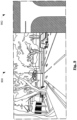
- Fig. 6 shows an example overlay image 600 with an example key marker generated by the artificial neural network.
- an image may be captured by the FFC 202, when the vehicle is approaching an intersection.
- the Fusion Engine 210 of Fig. 2 may collect that image (or a plurality of the captured images) as a first training data subset for the artificial neural network, and may further obtain, as a second training data subset, image-related coordinates of the navigation key points/markers related to the image (or the plurality of images) of the first training data subset. Furthermore, the Fusion Engine 210 may supply both first training data subset and second data training subset to the artificial neural network as a training dataset.
- contours are determined by a neural network and post-processed so that, e. g., a maximum value, or individual center of mass positions can be determined.
- Fig. 7 illustrates an example three-step process of processing of the forward facing camera image according to an embodiment of the present disclosure.
- the image 700 from a forward facing camera serves as an input.
- the artificial neural network then processes the image using a semantic approach. Different areas of the image, covered by different types of objects, are identified: The street, other vehicles, stationary objects, the sky, and lane/street delimitations.
- Image 702 illustrates the intermediate (processed) image. Lines correspond to borders between areas related to different types of objects.
- the navigation key point is determined based on this semantic understanding of the image. This approach allows determining the navigation key point even if its location is occluded by other objects.
- the result is shown in image 704, where the marker 706 indicates the location of the navigation key point.
- the Fusion Engine 210 may determine a confidence value for the image-related coordinates.
- the confidence value may be determined for the image-related coordinates.
- the confidence value indicates a probability that the image-related coordinates are the correct coordinates of the navigation key point. Thereby, it can indicate whether the coordinates have been determined correctly.
- the first training data subset can comprise one or more images for which the artificial neural network determines a confidence value below a predefined threshold. Therefore, the training of the neural network can be performed more efficiently.
- the artificial neural network can be a convolutional neural network, as discussed above in Fig. 3 .
- the weights of the convolutional neural network can be set such that the convolutional neural network predicts navigation key point marker locations as close as possible to the locations of the navigation key point markers included in the second training data subset.
- the coordinates of second training data subset can be obtained through at least one of user input, one or more crowdsourcing platforms, and providing established geocentric positions of the key points in the pre-determined region.
- the image-related coordinates may indicate the position of navigation key points on an image. They may be expressed as pixel row and column numbers. Processing may comprise the generation of a heat map depicting values of the probability that a point on the image is the navigation key point. Processing may further comprise additional image processing steps known in the art.
- the navigation key points may be used to correctly display instructions to a driver. This may be achieved by superimposing instructions, street names, and other output over a camera image or a similar depiction of the surroundings of the mobile device.
- the method further comprises translating the image-related coordinates into geocentric coordinates as described with regard to the Marker Rendering Engine 114. This is possible since the navigation key points relate to stationary objects, such as road signs, intersection corners, and lanes.
- the artificial neural network and/or deep neural network as described above may exploit HRNet architectural features with task-specific modifications, as shown in 800 of Fig. 8 .
- Fig. 9 shows another example camera image 900, and a schematic top-view map 902 generated from a standard definition (SD) road map.
- a schematic top-view map 902 may alternatively be generated from an aerial or satellite image, and may be stored in a memory in the vehicle, and/or in a network-accessible server.
- the top-view map 902 may also be a purely topological map, wherein roads and their connections are presented as edges and vertices of a graph with known coordinates.
- satellite, aerial, or map images, such as standard definition (SD) maps may be used directly, wherein the SD maps consist of roads and intersections.
- both images may be used as an input for processing, such that the predicted navigation key points are superimposed onto the standard definition (SD) map, thereby increasing the reliability and accuracy of the determination of a navigation key point.
- SD standard definition
- either the camera image 900 or the schematic top-view image 902 may be perspectively transformed so that image coordinates (pixel row and column) of both input images relate to the same geocentric coordinates. This is particularly helpful when the quality of the camera image is low due to bad weather (e. g. fog) or other circumstances (e. g. impurities on the camera).
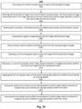
- Fig. 10 shows a flow diagram 1000 of an embodiment of the method of the disclosure.
- a first vehicle mounted camera is instructed to capture a first plurality of images.
- the first vehicle mounted camera may be a FFC 202 as discussed above, and may be instructed by a VO unit 204 as described above.
- Step 1004 calls for the first plurality of images to be received, wherein the first plurality of images comprise at least a first image captured at a first time interval and a second image captured at a second time interval after the first time interval.
- the method calls for receiving GPS coordinates, Inertial Measurement Unit (IMU) measurements, and the vehicle's velocity.
- IMU Inertial Measurement Unit
- the GPS coordinates are received from the GNSS module 208 as described above, whereas the IMU measurements are received from the IMU module 206 as described above. All measurements are received at the Fusion Engine 210 as describe above.
- the VO unit 204 computes the angular changes between the first image and the second image, and at step 1010 the VO unit 204 determines the vehicle's position and heading vector from the computed angular changes. This allows for the navigation system of a vehicle to determine the vehicle's position and heading vector in real-time, which allows the system to reliably use Augmented Reality to predict turn points and lane changes as discussed above.
- Step 1012 at least one of the first plurality of images is collected, as a first training subset, by the Fusion Engine 210.
- a second training data subset is obtained from image-related coordinates of navigation key points related to the at least one image of the first training data subset.
- the method continues with step 1016, wherein the first training data subset and the second training data subset are supplied to an artificial neural network (such as the deep neural network of Fig. 3 ) as a training dataset. Therefore, the Fusion Engine 210 can train the artificial neural network on the training dataset to predict image-related coordinates of navigation key points indicative of road sign locations and/or turn points as set out in step 1018.
- the input dataset is processed by the artificial neural network to predict image-related coordinates of navigation key points indicative of road sign locations and/or turn points.
Landscapes
- Engineering & Computer Science (AREA)
- Radar, Positioning & Navigation (AREA)
- Remote Sensing (AREA)
- Physics & Mathematics (AREA)
- General Physics & Mathematics (AREA)
- Automation & Control Theory (AREA)
- Computer Vision & Pattern Recognition (AREA)
- Theoretical Computer Science (AREA)
- Multimedia (AREA)
- Navigation (AREA)
Claims (10)
- Computerimplementiertes Verfahren (1000) zum Bestimmen einer Position eines Fahrzeugs und zum Vorhersagen von wichtigen Navigationspunkten, wobei das Verfahren die folgenden Schritte umfasst:Anweisen (1002) einer ersten an einem Fahrzeug montierten Kamera, eine erste Vielzahl von Bildern aufzunehmen;Empfangen (1004) der ersten Vielzahl von Bildern von der ersten an einem Fahrzeug montierten Kamera, wobei die erste Vielzahl von Bildern mindestens ein erstes Bild, das in einem ersten Zeitintervall aufgenommen wurde, und ein zweites Bild, das in einem zweiten Zeitintervall nach dem ersten Zeitintervall aufgenommen wurde, umfasst;Empfangen (1006) von GPS-Koordinaten, Inertiale-Messeinheits-(IMU-)Messungen und der Geschwindigkeit des Fahrzeugs;Berechnen (1008) der Winkeländerungen zwischen dem ersten Bild und dem zweiten Bild;Bestimmen der Position und des Kursvektors des Fahrzeugs mit den berechneten Winkeländerungen;Bestimmen eines Konfidenzwertes für die bestimmte Position und den bestimmten Kursvektor des Fahrzeugs basierend auf den empfangenen GPS-Koordinaten, IMU-Messungen und der Geschwindigkeit des Fahrzeugs;Sammeln (1012) von mindestens einem Bild der ersten Vielzahl von Bildern als ersten Trainingsdatenteilsatz;Erlangen (1014) von bildbetreffenden Koordinaten von wichtigen Navigationspunkten, die das mindestens eine Bild des ersten Trainingsdatenteilsatzes betreffen, als einen zweiten Trainingsdatenteilsatz;Speisen (1016) eines künstlichen neuronalen Netzwerks mit dem ersten Trainingsdatenteilsatz und dem zweiten Trainingsdatenteilsatz als Trainingsdatensatz;Trainieren (1018) des künstlichen neuronalen Netzwerks anhand des Trainingsdatensatzes, um bildbetreffende Koordinaten von wichtigen Navigationspunkten vorherzusagen, die Positionen von Straßenschildern und/oder Wendepunkte anzeigen; undVerarbeiten (1020) von Bildern der ersten an einem Fahrzeug montierten Kamera als Eingabedatensatz durch das künstliche neuronale Netzwerk, um bildbetreffende Koordinaten von wichtigen Navigationspunkten vorherzusagen, die Positionen von Straßenschildern und/oder Wendepunkte anzeigen.
- Computerimplementiertes Verfahren (1000) nach Anspruch 1, ferner umfassend:Anweisen der ersten an einem Fahrzeug montierten Kamera, eine zweite Vielzahl von Bildern aufzunehmen, wenn der Konfidenzwert unter einem vorbestimmten Schwellenwert ist; undEmpfangen der zweiten Vielzahl von Bildern von der ersten an einem Fahrzeug montierten Kamera, wobei:die zweite Vielzahl von Bildern mindestens ein drittes Bild, das in einem dritten Zeitintervall aufgenommen wurde, und ein viertes Bild, das in einem vierten Zeitintervall nach dem dritten Zeitintervall aufgenommen wurde, umfasst; unddie Zeitdifferenz zwischen dem dritten Zeitintervall und dem vierten Zeitintervall kürzer ist als die Zeitdifferenz zwischen dem ersten Zeitintervall und dem zweiten Zeitintervall,wobei das Verfahren ferner Folgendes umfasst:Berechnen der Winkeländerungen zwischen dem dritten Bild und dem vierten Bild; undBestimmen der Position und des Kursvektors des Fahrzeugs aus den berechneten Winkeländerungen zwischen dem dritten Bild und dem vierten Bild.
- Computerimplementiertes Verfahren (1000) nach Anspruch 1 oder 2, ferner umfassend:Anweisen einer zweiten an einem Fahrzeug montierten Kamera, eine dritte Vielzahl von Bildern aufzunehmen; undEmpfangen der dritten Vielzahl von Bildern von der zweiten an einem Fahrzeug montierten Kamera.
- Computerimplementiertes Verfahren (1000) nach einem der Ansprüche 1 bis 3, ferner umfassend:
Übersetzen der bildbetreffenden Koordinaten in geozentrische Koordinaten und optional Speichern der geozentrischen Koordinaten in einer Speichervorrichtung, die von einer mobilen Vorrichtung und/oder von einem über das Netzwerk zugänglichen Server umfasst ist. - Computerimplementierte Verfahren (1000) nach einem der Ansprüche 1 bis 4, wobei die Koordinaten des zweiten Trainingsdatenteilsatzes durch mindestens eines von einer Benutzereingabe, einer oder mehreren Crowdsourcing-Plattformen und Bereitstellen etablierter geozentrischer Positionen der wichtigen Punkte in der vorbestimmten Region erlangt werden und/oder wobei das künstliche neuronale Netzwerk ein konvolutionelles neuronales Netzwerk ist.
- Computerimplementiertes Verfahren (1000) nach einem der Ansprüche 1 bis 5, ferner umfassend:Speisen eines zweiten künstlichen neuronalen Netzwerks mit dem ersten Trainingsdatenteilsatz als Eingabedaten;Vorhersagen von bildbetreffenden Koordinaten von wichtigen Navigationspunkten durch das zweite neuronale Netzwerk basierend auf dem ersten Trainingsdatenteilsatz; undBestimmen eines weiteren Konfidenzwertes, der die Abstände zwischen den von dem trainierten künstlichen neuronalen Netzwerk und dem zweiten künstlichen neuronalen Netzwerk vorhergesagten Positionen der wichtigen Navigationspunkte anzeigt.
- Computerimplementiertes Verfahren (1000) nach einem der Ansprüche 1 bis 6, ferner umfassend:
Überlagern der vorhergesagten wichtigen Navigationspunkte auf einer Standardauflösungs (SD) karte, wobei die SD-Karte aus Straßen und Kreuzungen besteht. - Vorrichtung zum Bestimmen einer Position eines Fahrzeugs und zum Vorhersagen von wichtigen Navigationspunkten, wobei die Vorrichtung Folgendes umfasst:eine erste an einem Fahrzeug montierte Kamera;ein mit der Logik gekoppeltes Global-Navigation-Satellite-System-(GNSS-)Modul, wobei das GNSS-Modul betreibbar ist, um GPS-Koordinaten zu empfangen;eine mit der Logik gekoppelte inertiale Messeinheit (IMU), wobei die IMU betreibbar ist, um IMU-Messungen zu empfangen; undmit der ersten an einem Fahrzeug montierten Kamera gekoppelte Logik, wobei die Logik betreibbar ist, um:die Geschwindigkeit des Fahrzeugs zu empfangen;die erste an einem Fahrzeug montierte Kamera anzuweisen, eine erste Vielzahl von Bildern aufzunehmen;die erste Vielzahl von Bildern von der ersten an einem Fahrzeug montierten Kamera zu empfangen, wobei die erste Vielzahl von Bildern mindestens ein erstes Bild, das in einem ersten Zeitintervall aufgenommen wurde, und ein zweites Bild, das in einem zweiten Zeitintervall nach dem ersten Zeitintervall aufgenommen wurde, umfasst;die Winkeländerungen zwischen dem ersten Bild und dem zweiten Bild zu berechnen;die Position und den Kursvektor des Fahrzeugs mit den berechneten Winkeländerungen zu bestimmen;einen Konfidenzwert für die bestimmte Position und den bestimmten Kursvektor des Fahrzeugs basierend auf den empfangenen GPS-Koordinaten, IMU-Messungen und der Geschwindigkeit des Fahrzeugs zu bestimmen;mindestens ein Bild der ersten Vielzahl von Bildern als einen ersten Trainingsdatenteilsatz zu sammeln;bildbetreffende Koordinaten von wichtigen Navigationspunkten zu erlangen, die das mindestens eine Bild des ersten Trainingsdatenteilsatzes betreffen, als einen zweiten Trainingsdatenteilsatz;ein künstliches neuronales Netzwerk mit dem ersten Trainingsdatenteilsatz und dem zweiten Trainingsdatenteilsatz als Trainingsdatensatz zu speisen;das künstliche neuronale Netzwerk anhand des Trainingsdatensatzes zu trainieren, um bildbetreffende Koordinaten von wichtigen Navigationspunkten vorherzusagen, die Positionen von Straßenschildern und/oder Wendepunkte anzeigen; undBilder der ersten an einem Fahrzeug montierten Kamera als Eingabedatensatz durch das künstliche neuronale Netzwerk zu verarbeiten, um bildbetreffende Koordinaten von wichtigen Navigationspunkten vorherzusagen, die Positionen von Straßenschildern und/oder Wendepunkte anzeigen.
- Vorrichtung nach Anspruch 8, wobei die Logik ferner betreibbar ist, um die Schritte nach einem der Ansprüche 2 bis 7 durchzuführen.
- Vorrichtung nach Anspruch 8 oder 9, ferner umfassend eine zweite an einem Fahrzeug montierte Kamera, die mit der Logik gekoppelt ist, wobei die zweite an einem Fahrzeug montierte Kamera betreibbar ist, um eine zweite Vielzahl von Bildern aufzunehmen.
Applications Claiming Priority (1)
| Application Number | Priority Date | Filing Date | Title |
|---|---|---|---|
| PCT/RU2020/000400 WO2022025786A1 (en) | 2020-07-31 | 2020-07-31 | Vision-based location and turn marker prediction |
Publications (2)
| Publication Number | Publication Date |
|---|---|
| EP4189329A1 EP4189329A1 (de) | 2023-06-07 |
| EP4189329B1 true EP4189329B1 (de) | 2025-06-25 |
Family
ID=72615927
Family Applications (1)
| Application Number | Title | Priority Date | Filing Date |
|---|---|---|---|
| EP20776249.3A Active EP4189329B1 (de) | 2020-07-31 | 2020-07-31 | Sichtbasierte positions- und wendemarkervorhersage |
Country Status (4)
| Country | Link |
|---|---|
| US (1) | US12546608B2 (de) |
| EP (1) | EP4189329B1 (de) |
| CN (1) | CN115917255B (de) |
| WO (1) | WO2022025786A1 (de) |
Families Citing this family (4)
| Publication number | Priority date | Publication date | Assignee | Title |
|---|---|---|---|---|
| CN115035488B (zh) * | 2021-02-23 | 2026-02-06 | 北京原创世代科技有限公司 | 一种车道线角点检测方法、装置、电子设备及存储介质 |
| CN115019537B (zh) * | 2022-06-20 | 2023-11-14 | 芜湖宏景电子股份有限公司 | 一种应用于低质量网络条件下的智能导航系统 |
| JP7602516B2 (ja) * | 2022-08-31 | 2024-12-18 | ウーブン・バイ・トヨタ株式会社 | 地図更新装置、地図更新方法及び地図更新用コンピュータプログラム |
| CN119334970B (zh) * | 2024-12-05 | 2025-05-02 | 宁德时代新能源科技股份有限公司 | 视觉系统的评估方法、装置、系统、电子设备及存储介质 |
Family Cites Families (11)
| Publication number | Priority date | Publication date | Assignee | Title |
|---|---|---|---|---|
| KR102819289B1 (ko) * | 2016-12-14 | 2025-06-11 | 삼성전자주식회사 | 영상에 포함된 도로와 관련된 정보를 결정하는 뉴럴 네트워크를 학습시키는 학습 데이터를 생성하는 장치 및 방법 |
| WO2019023628A1 (en) | 2017-07-27 | 2019-01-31 | Waymo Llc | NEURAL NETWORKS FOR VEHICLE TRACK PLANNING |
| US10929713B2 (en) * | 2017-10-17 | 2021-02-23 | Sri International | Semantic visual landmarks for navigation |
| CN112204349B (zh) * | 2018-04-03 | 2024-10-18 | 御眼视觉技术有限公司 | 用于车辆导航的系统和方法 |
| WO2020048623A1 (en) | 2018-09-07 | 2020-03-12 | Huawei Technologies Co., Ltd. | Estimation of a pose of a robot |
| US10902634B2 (en) * | 2018-12-04 | 2021-01-26 | Here Global B.V. | Method and apparatus for providing feature triangulation |
| CN109815300B (zh) | 2018-12-13 | 2021-06-29 | 北京邮电大学 | 一种车辆定位方法 |
| WO2020139356A1 (en) | 2018-12-27 | 2020-07-02 | Didi Research America, Llc | Image pre-processing in a lane marking determination system |
| JP2022536030A (ja) * | 2019-06-03 | 2022-08-12 | エヌビディア コーポレーション | ビデオ分析アプリケーションにおける相関フィルタを使用した複数物体追跡 |
| DE102019216548A1 (de) * | 2019-10-28 | 2021-04-29 | DeepUp GmbH | Verfahren und mobile Erfassungsvorrichtung zur Erfassung von Infrastrukturelementen eines unterirdischen Leitungsnetzwerks |
| CN111275000B (zh) | 2020-02-18 | 2023-05-02 | 广州敏视数码科技有限公司 | 基于历史定位数据的交通标志牌检测方法 |
-
2020
- 2020-07-31 US US18/040,130 patent/US12546608B2/en active Active
- 2020-07-31 WO PCT/RU2020/000400 patent/WO2022025786A1/en not_active Ceased
- 2020-07-31 CN CN202080102752.2A patent/CN115917255B/zh active Active
- 2020-07-31 EP EP20776249.3A patent/EP4189329B1/de active Active
Also Published As
| Publication number | Publication date |
|---|---|
| CN115917255B (zh) | 2025-11-21 |
| CN115917255A (zh) | 2023-04-04 |
| US20230273029A1 (en) | 2023-08-31 |
| US12546608B2 (en) | 2026-02-10 |
| WO2022025786A1 (en) | 2022-02-03 |
| EP4189329A1 (de) | 2023-06-07 |
Similar Documents
| Publication | Publication Date | Title |
|---|---|---|
| EP3732657B1 (de) | Fahrzeuglokalisierung | |
| CN112204343B (zh) | 高清晰地图数据的可视化 | |
| US11676296B2 (en) | Augmenting reality using semantic segmentation | |
| EP4189329B1 (de) | Sichtbasierte positions- und wendemarkervorhersage | |
| CN107328410B (zh) | 用于定位自动驾驶车辆的方法和汽车电脑 | |
| JP6694395B2 (ja) | デジタル地図に対する位置を決定する方法およびシステム | |
| US20100176987A1 (en) | Method and apparatus to estimate vehicle position and recognized landmark positions using GPS and camera | |
| KR20200023865A (ko) | 차선 결정 방법 및 장치 | |
| JP6520740B2 (ja) | 物体検出方法、物体検出装置、およびプログラム | |
| US12061252B2 (en) | Environment model using cross-sensor feature point referencing | |
| US11474193B2 (en) | Camera calibration for localization | |
| US20220122316A1 (en) | Point cloud creation | |
| US12326346B2 (en) | Apparatus, method, and computer program for collecting feature data | |
| JP7613406B2 (ja) | 地物検出装置、地物検出方法及び地物検出用コンピュータプログラム | |
| US20210080264A1 (en) | Estimation device, estimation method, and computer program product | |
| US12196569B2 (en) | System and method for vehicle-mounted navigation key point localization | |
| CN116772889A (zh) | 地图更新区间决定装置、地图更新区间决定方法及地图更新区间决定用计算机程序 | |
| JP2023169631A (ja) | 車両制御装置、車両制御方法及び車両制御用コンピュータプログラム | |
| CN118968468A (zh) | 用于车载视频处理系统的障碍物尺寸识别方法及相关设备 | |
| TWI657230B (zh) | 導航定位裝置及應用其之導航定位方法 | |
| EP4361961A1 (de) | Verfahren zur bestimmung von informationen bezüglich eines verkehrsteilnehmers | |
| Hu et al. | Real-time data fusion on stabilizing camera pose estimation output for vision-based road navigation | |
| JP2024546752A (ja) | モバイルデバイスによるリアルタイムマッピングのための信頼性の高いアンカーポイント | |
| CN120358325A (zh) | 图像处理装置 | |
| CN115187762A (zh) | 一种车载地图的渲染方法和装置、车辆、以及存储介质 |
Legal Events
| Date | Code | Title | Description |
|---|---|---|---|
| STAA | Information on the status of an ep patent application or granted ep patent |
Free format text: STATUS: UNKNOWN |
|
| STAA | Information on the status of an ep patent application or granted ep patent |
Free format text: STATUS: THE INTERNATIONAL PUBLICATION HAS BEEN MADE |
|
| PUAI | Public reference made under article 153(3) epc to a published international application that has entered the european phase |
Free format text: ORIGINAL CODE: 0009012 |
|
| STAA | Information on the status of an ep patent application or granted ep patent |
Free format text: STATUS: REQUEST FOR EXAMINATION WAS MADE |
|
| 17P | Request for examination filed |
Effective date: 20230125 |
|
| AK | Designated contracting states |
Kind code of ref document: A1 Designated state(s): AL AT BE BG CH CY CZ DE DK EE ES FI FR GB GR HR HU IE IS IT LI LT LU LV MC MK MT NL NO PL PT RO RS SE SI SK SM TR |
|
| DAV | Request for validation of the european patent (deleted) | ||
| DAX | Request for extension of the european patent (deleted) | ||
| STAA | Information on the status of an ep patent application or granted ep patent |
Free format text: STATUS: EXAMINATION IS IN PROGRESS |
|
| 17Q | First examination report despatched |
Effective date: 20240325 |
|
| RIC1 | Information provided on ipc code assigned before grant |
Ipc: G06V 20/56 20220101ALI20241113BHEP Ipc: G01C 21/16 20060101ALI20241113BHEP Ipc: G01C 21/36 20060101AFI20241113BHEP |
|
| GRAP | Despatch of communication of intention to grant a patent |
Free format text: ORIGINAL CODE: EPIDOSNIGR1 |
|
| STAA | Information on the status of an ep patent application or granted ep patent |
Free format text: STATUS: GRANT OF PATENT IS INTENDED |
|
| INTG | Intention to grant announced |
Effective date: 20250115 |
|
| GRAS | Grant fee paid |
Free format text: ORIGINAL CODE: EPIDOSNIGR3 |
|
| GRAA | (expected) grant |
Free format text: ORIGINAL CODE: 0009210 |
|
| STAA | Information on the status of an ep patent application or granted ep patent |
Free format text: STATUS: THE PATENT HAS BEEN GRANTED |
|
| AK | Designated contracting states |
Kind code of ref document: B1 Designated state(s): AL AT BE BG CH CY CZ DE DK EE ES FI FR GB GR HR HU IE IS IT LI LT LU LV MC MK MT NL NO PL PT RO RS SE SI SK SM TR |
|
| P01 | Opt-out of the competence of the unified patent court (upc) registered |
Free format text: CASE NUMBER: APP_23246/2025 Effective date: 20250515 |
|
| REG | Reference to a national code |
Ref country code: GB Ref legal event code: FG4D |
|
| REG | Reference to a national code |
Ref country code: CH Ref legal event code: EP |
|
| REG | Reference to a national code |
Ref country code: DE Ref legal event code: R096 Ref document number: 602020053369 Country of ref document: DE |
|
| REG | Reference to a national code |
Ref country code: CH Ref legal event code: EP |
|
| REG | Reference to a national code |
Ref country code: IE Ref legal event code: FG4D |
|
| PG25 | Lapsed in a contracting state [announced via postgrant information from national office to epo] |
Ref country code: FI Free format text: LAPSE BECAUSE OF FAILURE TO SUBMIT A TRANSLATION OF THE DESCRIPTION OR TO PAY THE FEE WITHIN THE PRESCRIBED TIME-LIMIT Effective date: 20250625 |
|
| PGFP | Annual fee paid to national office [announced via postgrant information from national office to epo] |
Ref country code: DE Payment date: 20250724 Year of fee payment: 6 |
|
| REG | Reference to a national code |
Ref country code: LT Ref legal event code: MG9D |
|
| PG25 | Lapsed in a contracting state [announced via postgrant information from national office to epo] |
Ref country code: NO Free format text: LAPSE BECAUSE OF FAILURE TO SUBMIT A TRANSLATION OF THE DESCRIPTION OR TO PAY THE FEE WITHIN THE PRESCRIBED TIME-LIMIT Effective date: 20250925 Ref country code: GR Free format text: LAPSE BECAUSE OF FAILURE TO SUBMIT A TRANSLATION OF THE DESCRIPTION OR TO PAY THE FEE WITHIN THE PRESCRIBED TIME-LIMIT Effective date: 20250926 |
|
| PG25 | Lapsed in a contracting state [announced via postgrant information from national office to epo] |
Ref country code: BG Free format text: LAPSE BECAUSE OF FAILURE TO SUBMIT A TRANSLATION OF THE DESCRIPTION OR TO PAY THE FEE WITHIN THE PRESCRIBED TIME-LIMIT Effective date: 20250625 |
|
| PGFP | Annual fee paid to national office [announced via postgrant information from national office to epo] |
Ref country code: GB Payment date: 20250725 Year of fee payment: 6 |
|
| PG25 | Lapsed in a contracting state [announced via postgrant information from national office to epo] |
Ref country code: HR Free format text: LAPSE BECAUSE OF FAILURE TO SUBMIT A TRANSLATION OF THE DESCRIPTION OR TO PAY THE FEE WITHIN THE PRESCRIBED TIME-LIMIT Effective date: 20250625 |
|
| PG25 | Lapsed in a contracting state [announced via postgrant information from national office to epo] |
Ref country code: RS Free format text: LAPSE BECAUSE OF FAILURE TO SUBMIT A TRANSLATION OF THE DESCRIPTION OR TO PAY THE FEE WITHIN THE PRESCRIBED TIME-LIMIT Effective date: 20250925 |
|
| PG25 | Lapsed in a contracting state [announced via postgrant information from national office to epo] |
Ref country code: LV Free format text: LAPSE BECAUSE OF FAILURE TO SUBMIT A TRANSLATION OF THE DESCRIPTION OR TO PAY THE FEE WITHIN THE PRESCRIBED TIME-LIMIT Effective date: 20250625 |
|
| REG | Reference to a national code |
Ref country code: NL Ref legal event code: MP Effective date: 20250625 |
|
| PG25 | Lapsed in a contracting state [announced via postgrant information from national office to epo] |
Ref country code: NL Free format text: LAPSE BECAUSE OF FAILURE TO SUBMIT A TRANSLATION OF THE DESCRIPTION OR TO PAY THE FEE WITHIN THE PRESCRIBED TIME-LIMIT Effective date: 20250625 |
|
| PG25 | Lapsed in a contracting state [announced via postgrant information from national office to epo] |
Ref country code: PT Free format text: LAPSE BECAUSE OF FAILURE TO SUBMIT A TRANSLATION OF THE DESCRIPTION OR TO PAY THE FEE WITHIN THE PRESCRIBED TIME-LIMIT Effective date: 20251027 |
|
| REG | Reference to a national code |
Ref country code: AT Ref legal event code: MK05 Ref document number: 1806840 Country of ref document: AT Kind code of ref document: T Effective date: 20250625 |
|
| PG25 | Lapsed in a contracting state [announced via postgrant information from national office to epo] |
Ref country code: IS Free format text: LAPSE BECAUSE OF FAILURE TO SUBMIT A TRANSLATION OF THE DESCRIPTION OR TO PAY THE FEE WITHIN THE PRESCRIBED TIME-LIMIT Effective date: 20251025 |
|
| PG25 | Lapsed in a contracting state [announced via postgrant information from national office to epo] |
Ref country code: AT Free format text: LAPSE BECAUSE OF FAILURE TO SUBMIT A TRANSLATION OF THE DESCRIPTION OR TO PAY THE FEE WITHIN THE PRESCRIBED TIME-LIMIT Effective date: 20250625 Ref country code: SM Free format text: LAPSE BECAUSE OF FAILURE TO SUBMIT A TRANSLATION OF THE DESCRIPTION OR TO PAY THE FEE WITHIN THE PRESCRIBED TIME-LIMIT Effective date: 20250625 |
|
| PG25 | Lapsed in a contracting state [announced via postgrant information from national office to epo] |
Ref country code: CZ Free format text: LAPSE BECAUSE OF FAILURE TO SUBMIT A TRANSLATION OF THE DESCRIPTION OR TO PAY THE FEE WITHIN THE PRESCRIBED TIME-LIMIT Effective date: 20250625 |
|
| PG25 | Lapsed in a contracting state [announced via postgrant information from national office to epo] |
Ref country code: PL Free format text: LAPSE BECAUSE OF FAILURE TO SUBMIT A TRANSLATION OF THE DESCRIPTION OR TO PAY THE FEE WITHIN THE PRESCRIBED TIME-LIMIT Effective date: 20250625 |
|
| PG25 | Lapsed in a contracting state [announced via postgrant information from national office to epo] |
Ref country code: EE Free format text: LAPSE BECAUSE OF FAILURE TO SUBMIT A TRANSLATION OF THE DESCRIPTION OR TO PAY THE FEE WITHIN THE PRESCRIBED TIME-LIMIT Effective date: 20250625 |
|
| PG25 | Lapsed in a contracting state [announced via postgrant information from national office to epo] |
Ref country code: SK Free format text: LAPSE BECAUSE OF FAILURE TO SUBMIT A TRANSLATION OF THE DESCRIPTION OR TO PAY THE FEE WITHIN THE PRESCRIBED TIME-LIMIT Effective date: 20250625 |
|
| PG25 | Lapsed in a contracting state [announced via postgrant information from national office to epo] |
Ref country code: ES Free format text: LAPSE BECAUSE OF FAILURE TO SUBMIT A TRANSLATION OF THE DESCRIPTION OR TO PAY THE FEE WITHIN THE PRESCRIBED TIME-LIMIT Effective date: 20250625 |
|
| REG | Reference to a national code |
Ref country code: CH Ref legal event code: H13 Free format text: ST27 STATUS EVENT CODE: U-0-0-H10-H13 (AS PROVIDED BY THE NATIONAL OFFICE) Effective date: 20260224 |
|
| PG25 | Lapsed in a contracting state [announced via postgrant information from national office to epo] |
Ref country code: RO Free format text: LAPSE BECAUSE OF FAILURE TO SUBMIT A TRANSLATION OF THE DESCRIPTION OR TO PAY THE FEE WITHIN THE PRESCRIBED TIME-LIMIT Effective date: 20250625 Ref country code: LU Free format text: LAPSE BECAUSE OF NON-PAYMENT OF DUE FEES Effective date: 20250731 |
|
| REG | Reference to a national code |
Ref country code: BE Ref legal event code: MM Effective date: 20250731 |
|
| PG25 | Lapsed in a contracting state [announced via postgrant information from national office to epo] |
Ref country code: MC Free format text: LAPSE BECAUSE OF FAILURE TO SUBMIT A TRANSLATION OF THE DESCRIPTION OR TO PAY THE FEE WITHIN THE PRESCRIBED TIME-LIMIT Effective date: 20250625 |
|
| PG25 | Lapsed in a contracting state [announced via postgrant information from national office to epo] |
Ref country code: DK Free format text: LAPSE BECAUSE OF FAILURE TO SUBMIT A TRANSLATION OF THE DESCRIPTION OR TO PAY THE FEE WITHIN THE PRESCRIBED TIME-LIMIT Effective date: 20250625 |
|
| PG25 | Lapsed in a contracting state [announced via postgrant information from national office to epo] |
Ref country code: IT Free format text: LAPSE BECAUSE OF FAILURE TO SUBMIT A TRANSLATION OF THE DESCRIPTION OR TO PAY THE FEE WITHIN THE PRESCRIBED TIME-LIMIT Effective date: 20250625 Ref country code: BE Free format text: LAPSE BECAUSE OF NON-PAYMENT OF DUE FEES Effective date: 20250731 |
|
| PG25 | Lapsed in a contracting state [announced via postgrant information from national office to epo] |
Ref country code: CH Free format text: LAPSE BECAUSE OF NON-PAYMENT OF DUE FEES Effective date: 20250731 |
|
| PLBE | No opposition filed within time limit |
Free format text: ORIGINAL CODE: 0009261 |
|
| STAA | Information on the status of an ep patent application or granted ep patent |
Free format text: STATUS: NO OPPOSITION FILED WITHIN TIME LIMIT |