EP4189231B1 - System zur regelung eines wasserflusses durch eine hydroelektrische turbine - Google Patents
System zur regelung eines wasserflusses durch eine hydroelektrische turbine Download PDFInfo
- Publication number
- EP4189231B1 EP4189231B1 EP21759395.3A EP21759395A EP4189231B1 EP 4189231 B1 EP4189231 B1 EP 4189231B1 EP 21759395 A EP21759395 A EP 21759395A EP 4189231 B1 EP4189231 B1 EP 4189231B1
- Authority
- EP
- European Patent Office
- Prior art keywords
- water flow
- hydroelectric turbine
- regulation
- movable wall
- configuration
- Prior art date
- Legal status (The legal status is an assumption and is not a legal conclusion. Google has not performed a legal analysis and makes no representation as to the accuracy of the status listed.)
- Active
Links
Images



Classifications
-
- F—MECHANICAL ENGINEERING; LIGHTING; HEATING; WEAPONS; BLASTING
- F03—MACHINES OR ENGINES FOR LIQUIDS; WIND, SPRING, OR WEIGHT MOTORS; PRODUCING MECHANICAL POWER OR A REACTIVE PROPULSIVE THRUST, NOT OTHERWISE PROVIDED FOR
- F03B—MACHINES OR ENGINES FOR LIQUIDS
- F03B17/00—Other machines or engines
- F03B17/06—Other machines or engines using liquid flow with predominantly kinetic energy conversion, e.g. of swinging-flap type, "run-of-river", "ultra-low head"
- F03B17/062—Other machines or engines using liquid flow with predominantly kinetic energy conversion, e.g. of swinging-flap type, "run-of-river", "ultra-low head" with rotation axis substantially at right angle to flow direction
- F03B17/063—Other machines or engines using liquid flow with predominantly kinetic energy conversion, e.g. of swinging-flap type, "run-of-river", "ultra-low head" with rotation axis substantially at right angle to flow direction the flow engaging parts having no movement relative to the rotor during its rotation
-
- F—MECHANICAL ENGINEERING; LIGHTING; HEATING; WEAPONS; BLASTING
- F03—MACHINES OR ENGINES FOR LIQUIDS; WIND, SPRING, OR WEIGHT MOTORS; PRODUCING MECHANICAL POWER OR A REACTIVE PROPULSIVE THRUST, NOT OTHERWISE PROVIDED FOR
- F03B—MACHINES OR ENGINES FOR LIQUIDS
- F03B15/00—Controlling
- F03B15/02—Controlling by varying liquid flow
- F03B15/04—Controlling by varying liquid flow of turbines
- F03B15/06—Regulating, i.e. acting automatically
- F03B15/08—Regulating, i.e. acting automatically by speed, e.g. by measuring electric frequency or liquid flow
-
- F—MECHANICAL ENGINEERING; LIGHTING; HEATING; WEAPONS; BLASTING
- F05—INDEXING SCHEMES RELATING TO ENGINES OR PUMPS IN VARIOUS SUBCLASSES OF CLASSES F01-F04
- F05B—INDEXING SCHEME RELATING TO WIND, SPRING, WEIGHT, INERTIA OR LIKE MOTORS, TO MACHINES OR ENGINES FOR LIQUIDS COVERED BY SUBCLASSES F03B, F03D AND F03G
- F05B2240/00—Components
- F05B2240/10—Stators
- F05B2240/12—Fluid guiding means, e.g. vanes
-
- F—MECHANICAL ENGINEERING; LIGHTING; HEATING; WEAPONS; BLASTING
- F05—INDEXING SCHEMES RELATING TO ENGINES OR PUMPS IN VARIOUS SUBCLASSES OF CLASSES F01-F04
- F05B—INDEXING SCHEME RELATING TO WIND, SPRING, WEIGHT, INERTIA OR LIKE MOTORS, TO MACHINES OR ENGINES FOR LIQUIDS COVERED BY SUBCLASSES F03B, F03D AND F03G
- F05B2240/00—Components
- F05B2240/10—Stators
- F05B2240/13—Stators to collect or cause flow towards or away from turbines
- F05B2240/133—Stators to collect or cause flow towards or away from turbines with a convergent-divergent guiding structure, e.g. a Venturi conduit
-
- F—MECHANICAL ENGINEERING; LIGHTING; HEATING; WEAPONS; BLASTING
- F05—INDEXING SCHEMES RELATING TO ENGINES OR PUMPS IN VARIOUS SUBCLASSES OF CLASSES F01-F04
- F05B—INDEXING SCHEME RELATING TO WIND, SPRING, WEIGHT, INERTIA OR LIKE MOTORS, TO MACHINES OR ENGINES FOR LIQUIDS COVERED BY SUBCLASSES F03B, F03D AND F03G
- F05B2240/00—Components
- F05B2240/90—Mounting on supporting structures or systems
- F05B2240/91—Mounting on supporting structures or systems on a stationary structure
- F05B2240/916—Mounting on supporting structures or systems on a stationary structure with provision for hoisting onto the structure
-
- F—MECHANICAL ENGINEERING; LIGHTING; HEATING; WEAPONS; BLASTING
- F05—INDEXING SCHEMES RELATING TO ENGINES OR PUMPS IN VARIOUS SUBCLASSES OF CLASSES F01-F04
- F05B—INDEXING SCHEME RELATING TO WIND, SPRING, WEIGHT, INERTIA OR LIKE MOTORS, TO MACHINES OR ENGINES FOR LIQUIDS COVERED BY SUBCLASSES F03B, F03D AND F03G
- F05B2250/00—Geometry
- F05B2250/02—Geometry variable
-
- F—MECHANICAL ENGINEERING; LIGHTING; HEATING; WEAPONS; BLASTING
- F05—INDEXING SCHEMES RELATING TO ENGINES OR PUMPS IN VARIOUS SUBCLASSES OF CLASSES F01-F04
- F05B—INDEXING SCHEME RELATING TO WIND, SPRING, WEIGHT, INERTIA OR LIKE MOTORS, TO MACHINES OR ENGINES FOR LIQUIDS COVERED BY SUBCLASSES F03B, F03D AND F03G
- F05B2270/00—Control
- F05B2270/10—Purpose of the control system
- F05B2270/20—Purpose of the control system to optimise the performance of a machine
-
- F—MECHANICAL ENGINEERING; LIGHTING; HEATING; WEAPONS; BLASTING
- F05—INDEXING SCHEMES RELATING TO ENGINES OR PUMPS IN VARIOUS SUBCLASSES OF CLASSES F01-F04
- F05B—INDEXING SCHEME RELATING TO WIND, SPRING, WEIGHT, INERTIA OR LIKE MOTORS, TO MACHINES OR ENGINES FOR LIQUIDS COVERED BY SUBCLASSES F03B, F03D AND F03G
- F05B2270/00—Control
- F05B2270/30—Control parameters, e.g. input parameters
- F05B2270/34—Water level
-
- F—MECHANICAL ENGINEERING; LIGHTING; HEATING; WEAPONS; BLASTING
- F05—INDEXING SCHEMES RELATING TO ENGINES OR PUMPS IN VARIOUS SUBCLASSES OF CLASSES F01-F04
- F05B—INDEXING SCHEME RELATING TO WIND, SPRING, WEIGHT, INERTIA OR LIKE MOTORS, TO MACHINES OR ENGINES FOR LIQUIDS COVERED BY SUBCLASSES F03B, F03D AND F03G
- F05B2270/00—Control
- F05B2270/30—Control parameters, e.g. input parameters
- F05B2270/341—Liquid flow velocity or direction
-
- Y—GENERAL TAGGING OF NEW TECHNOLOGICAL DEVELOPMENTS; GENERAL TAGGING OF CROSS-SECTIONAL TECHNOLOGIES SPANNING OVER SEVERAL SECTIONS OF THE IPC; TECHNICAL SUBJECTS COVERED BY FORMER USPC CROSS-REFERENCE ART COLLECTIONS [XRACs] AND DIGESTS
- Y02—TECHNOLOGIES OR APPLICATIONS FOR MITIGATION OR ADAPTATION AGAINST CLIMATE CHANGE
- Y02E—REDUCTION OF GREENHOUSE GAS [GHG] EMISSIONS, RELATED TO ENERGY GENERATION, TRANSMISSION OR DISTRIBUTION
- Y02E10/00—Energy generation through renewable energy sources
- Y02E10/20—Hydro energy
Definitions
- the present invention relates to the field of hydroelectric power generation within canals.
- the invention relates to a system for the regulation of a water flow passing through a hydroelectric turbine.
- the canals for the flow of water are of the irrigation or energy type.
- the former are used to distribute water in the cultivated fields and can be gravity-fed or pumped, while the latter are created to feed power plants or to convey water into the natural riverbed, once the jump of the canal has been exploited upstream.
- Both categories of canal, with the exception of pumped irrigation canals, can be further exploited from the energy point of view by recovering kinetic energy through flowing water turbines.
- these canals are designed and sized according to a maximum flow rate which, although present in the canal only for short periods of the year, would in such periods lead to flooding of the canal due to the excess volume of the turbine immersed in the canal and not foreseen in the design phase, entailing significant safety problems, both for the operators and for the canal and the turbine itself.
- WO2011095240 discloses a hydroelectric power station comprising at least one rotor, a rotor-driven generator, a floating body and a nozzle assembly for increasing the flow rate in the rotor area.
- the nozzle assembly has at least one adjustable wall.
- the purpose of WO2011095240 is to vary the inclination of the adjustable walls so as to keep the flow speed constant in proximity to the rotor and, therefore, to keep the rotation speed of the rotor constant.
- WO2011095240 does not provide any system to control the flow upstream of the turbine in order to prevent flooding or system breakdowns.
- the system 100 comprises a working canal 110 arranged in a water flow having a main sliding direction d , a speed v u upstream of the turbine 200 and upstream of the system 100, a speed v t at the turbine 200, a speed v d downstream of the turbine 200 and a height h u of the free surface upstream of the system 100.
- the working canal 110 comprises two containing walls 115 and houses inside the hydroelectric turbine 200 itself.
- the system 100 comprises at least one sensor configured to measure at least one fluid dynamic parameter of the water flow.
- this sensor can be a speed sensor for measuring the value v u of the speed upstream of the system 100 or a sensor configured to measure one or more parameters p of the flow from which such value v u can be indirectly derived, such as the flowrate of the water flow.
- the present invention therefore allows to receive information regarding the hydrodynamic conditions of the water flow upstream of the system 100 and to modify the inclination of the movable walls 120a, 120b to intervene in the event that the water flow presents an excessive height and/or speed which could be dangerous for the system 100 or for the operators involved.
- the control unit is arranged to operate the movable walls 120a,120b, even individually, to arrange them in the neutral configuration, reducing the resistance opposed to the flow and avoiding unwanted increases in the water flow.
- control unit can operate the movable walls 120a,120b to increase the intensity of the flow at the turbine 200, in the event that the flow rate is not sufficient to produce the desired efficiency.
- control unit is adapted to operate the movable walls 120a,120b to increase the angle ⁇ by arranging them in the flow acceleration configuration.
- the system 100 allows the flow to be conveyed in a sort of converging duct, generating an increase in speed.
- the system works in the neutral configuration and the movable walls 120a, 120b are substantially transparent to the water flow, not accelerating it in correspondence with the turbine.
- control unit is adapted to control the movable walls 120a, 120b to vary the angle ⁇ in an inversely proportional manner to the speed value v u .
- control unit can adjust the value of the angle ⁇ as a function of the speed v u to keep the speed v t of the flow inside the turbine substantially constant, guaranteeing, within certain limits, a constant working speed and improving the efficiency of the turbine.
- the system 100 also comprises two auxiliary movable walls 130a,130b located downstream of the hydroelectric turbine 200 and also configured to switch between a neutral configuration, wherein v t ⁇ v d , and at least one flow deceleration configuration, wherein v t > v d .
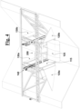
- the auxiliary movable walls 130 are arranged in the neutral configuration in both Figs. 3 and 4 .
- auxiliary movable walls 130a,130b reduces the turbulence downstream of the turbine, increasing the efficiency of the turbine's electricity generation process.
- the system 100 also comprises a release mechanism arranged to arrange the auxiliary movable walls 130a,130b between a constrained configuration, wherein they are constrained to keep the angle ⁇ ' constant, and a released configuration, in which they are free to rotate about its rotation axis y ' orienting themselves according to the hydrodynamic forces expressed by the water flow.
- the release mechanism allows to release the movable wall or the movable walls downstream of the turbine in case of excessive flow rate, so as to allow the movable wall to orient itself according to the hydrodynamic forces expressed by the water flow, guaranteeing the safety of the system.
- the system 100 can provide a further release mechanism adapted to arrange the movable walls 120a,120b between a constrained configuration, in which they are constrained to keep the angle ⁇ constant, and a released configuration, in which the movable walls 120a, 120b are arranged in the neutral configuration, reducing the resistance to the water flow.
- Both release mechanisms can be operated, for example, in the event that there is a fault in the system 100 and the control unit is unable to control the movable walls 120a,120b and/or the auxiliary movable walls 130a,130b.
- the release mechanisms make it possible to reduce the resistance of the walls to the water flow, avoiding dangerous increases in the height and/or speed of the flow itself.
- the mechanism comprises a housing 151, a sliding element 153', a wedge 152 and two pins 153.
- the pins 153 can translate vertically, integrally to the sliding element 153', bringing two springs 154 into compression or expansion.
- the wedge 152 is not pulled by external forces and remains steadily in its housing.
- the pins 153 slide upwards compressing the springs 154.
- the pulling action exceeds a predetermined threshold, the wedge is released from the sliding element 153', disengaging from the housing 151, as shown in Fig. 5B .
- the release mechanism 150 of Figs. 5A and 5B can be applied both to the movable walls 120a,120b and to the auxiliary movable walls 130a,130b. In this case, when these walls undergo a flow force greater than a certain threshold, in the relative release mechanisms 150 the wedges 151 are released from their respective housings 151, disconnecting the movable walls from the relative actuation systems and leading them to follow the direction of the flow or, alternatively, in the neutral configuration which minimizes the resistance to the flow.
- the system 100 may comprise an emergency extraction device.
- the emergency extraction device allows removing the hydroelectric turbine 200 by the water flow.
- Such device is an emergency measure and can be activated, for example, in the event that the variation of the angle of the movable walls is insufficient to keep the flow rate of the water flow below a predetermined threshold and that this could jeopardize the structural integrity of the turbine 200 and/or the safety of the operators involved.
- the embodiments shown in Figs. 1 to 4 comprise two movable walls 120a,120b and, optionally, two auxiliary movable walls 130a,130b so as to be able to share the resistance opposed to the water flow, reducing the structural load of each movable wall.
- the present invention also intends to protect embodiments which comprise a single movable wall and/or a single auxiliary movable wall. These solutions may be necessary in case of small dimensions or particular geometry of the canals in which the system 100 is installed.
- the working channel In case of use of a single movable wall and/or a single auxiliary movable wall, the working channel must be placed laterally with respect to the main canal using a side wall of the main canal as a containment wall for the working canal.
- the system also provides a lifting device 140 arranged to vary the height of the hydroelectric turbine 200.
- the lifting device 140 allows adjust the height of the turbine 200 according to the level of the water flow, keeping it in the optimal position, i.e. completely immersed but close to the surface of the water.
- the senor configured to measure the height h u can allow the control unit to command the lifting device to vary the height of the turbine 200 according to the height of the detected water flow.
- the lifting device 140 can allow the extraction of the turbine in the event that the upstream flow is too high, in order to put the turbine in safety and avoid any flooding of the canal.
- the system 100 also provides a lower movable wall 125 arranged on the bottom at said working canal 110.
- the lower movable wall 125 may have an inclined geometry upwards at the turbine entrance and downwards at the turbine exit, to increase the convergent-divergent duct effect.
- the lower movable wall 125 can incline allowing to further increase the speed of the flow entering the turbine 200.
- At least one electrical energy accumulator is provided which is suitable for activating the movable walls and/or the auxiliary movable walls in the event of a power failure on the system network.
Landscapes
- Engineering & Computer Science (AREA)
- Chemical & Material Sciences (AREA)
- Combustion & Propulsion (AREA)
- Mechanical Engineering (AREA)
- General Engineering & Computer Science (AREA)
- Power Engineering (AREA)
- Control Of Water Turbines (AREA)
- Hydraulic Turbines (AREA)
Claims (14)
- System (100) zur Regulierung eines Wasserflusses durch eine hydroelektrische Turbine (200), wobei der Wasserfluss Folgendes aufweist:- eine Hauptgleitrichtung d;- eine Geschwindigkeit vu stromaufwärts des Systems (100);- eine Geschwindigkeit vt an der hydroelektrischen Turbine (200);- eine Geschwindigkeit vd stromabwärts der hydroelektrischen Turbine (200),- eine Höhe hu der freien Oberfläche stromaufwärts des Systems (100);wobei das System (100) Folgendes umfasst:- einen Arbeitskanal (110), der in dem Wasserfluss platziert ist und mindestens eine Seitenwand (115) umfasst, wobei der Arbeitskanal (110) in Verwendung dazu angeordnet ist, die hydroelektrische Turbine (200) unterzubringen;- mindestens eine bewegbare Wand (120a, 120b), die stromaufwärts der hydroelektrischen Turbine (200) gelegen und dazu konfiguriert ist, zwischen einer neutralen Konfiguration, in der vt ≅ vu, und mindestens einer Flussbeschleunigungskonfiguration, in der vt > vu, umzuschalten;wobei das System (100) dadurch gekennzeichnet ist, dass es außerdem Folgendes umfasst:- mindestens einen Sensor, der dazu angeordnet ist, Folgendes zu messen:- die Geschwindigkeit vu oder einen Parameter p, aus dem es möglich ist, die Geschwindigkeit vu zu berechnen;- die Höhe hu ;- eine Steuereinheit, die zu Folgendem angeordnet ist:- Empfangen der Geschwindigkeit vu oder des Parameters p und der Höhe hu ;- Betreiben der oder jeder bewegbaren Wand (120a, 120b), was zwischen der neutralen Konfiguration und der Flussbeschleunigungskonfiguration umschaltet, um die Geschwindigkeit vu und die Höhe hu geeignet zu variieren.
- System (100) zur Regulierung eines Wasserflusses durch eine hydroelektrische Turbine (200) nach Anspruch 1, wobei in dem Fall, dass die Geschwindigkeit vu geringer als eine vorbestimmte Schwellengeschwindigkeit

- System (100) zur Regulierung eines Wasserflusses durch eine hydroelektrische Turbine (200) nach Anspruch 1, wobei in dem Fall, dass die Höhe hu höher als eine vorbestimmte Schwellenhöhe

- System (100) zur Regulierung eines Wasserflusses durch eine hydroelektrische Turbine (200) nach Anspruch 1, wobei die oder jede bewegbare Wand (120a, 120b) eine ebene Oberfläche S umfasst, die dazu angeordnet ist, einen Winkel α in Bezug auf die Hauptgleitrichtung d zu bilden, wobei die oder jede bewegbare Wand (120a, 120b) dazu angeordnet ist, sich um eine Drehachse y zu drehen, was den Winkel α ändert, um zwischen der neutralen Konfiguration, in der α = 0, und mindestens einer Flussbeschleunigungskonfiguration, in der α > 0, umzuschalten.
- System (100) zur Regulierung eines Wasserflusses durch eine hydroelektrische Turbine (200) nach Anspruch 4, wobei die Steuereinheit dazu angeordnet ist, die oder jede bewegbare Wand (120a, 120b) zu betreiben, um den Winkel α auf eine Weise einzustellen, die umgekehrt proportional zu der Geschwindigkeit vu ist.
- System (100) zur Regulierung eines Wasserflusses durch eine hydroelektrische Turbine (200) nach Anspruch 4, wobei ein Freigabemechanismus bereitgestellt ist, der dazu angeordnet ist, die oder jede bewegbare Wand (120a, 120b) zwischen einer eingeschränkten Konfiguration, in der die oder jede bewegbare Wand (120a, 120b) eingeschränkt ist, um den Winkel α konstant zu halten, und einer freigegebenen Konfiguration, in der die oder jede bewegbare Wand (120a, 120b) in die neutrale Konfiguration umschaltet, anzuordnen.
- System (100) zur Regulierung eines Wasserflusses durch eine hydroelektrische Turbine (200) nach einem der vorhergehenden Ansprüche, wobei mindestens eine bewegbare Hilfswand (130a, 130b) ebenfalls bereitgestellt ist, die stromabwärts der hydroelektrischen Turbine (200) gelegen und dazu konfiguriert ist, zwischen einer neutralen Konfiguration, in der vt = vd, und mindestens einer Flussverlangsamungskonfiguration, in der vt > vd, umzuschalten.
- System (100) zur Regulierung eines Wasserflusses durch eine hydroelektrische Turbine (200) nach Anspruch 7, wobei die oder jede bewegbare Hilfswand (130a, 130b) eine ebene Oberfläche S' umfasst, die dazu angeordnet ist, einen Winkel α' in Bezug auf die Hauptgleitrichtung d zu bilden, wobei die oder jede bewegbare Hilfswand (130a, 130b) dazu angeordnet ist, sich um eine Drehachse y' zu drehen, was den Winkel α' ändert, um zwischen der neutralen Konfiguration, in der α' = 0, und mindestens einer Flussverlangsamungskonfiguration, in der α' > 0, umzuschalten.
- System (100) zur Regulierung eines Wasserflusses durch eine hydroelektrische Turbine (200) nach Anspruch 8, wobei ein Freigabemechanismus bereitgestellt ist, der dazu angeordnet ist, die oder jede bewegbare Hilfswand (130a, 130b) zwischen einer eingeschränkten Konfiguration, in der die oder jede bewegbare Hilfswand (130a, 130b) eingeschränkt ist, um den Winkel α' konstant zu halten, und einer freigegebenen Konfiguration, in der die oder jede bewegbare Hilfswand (130a, 130b) sich frei um die Drehachse y' drehen kann, was sie selbst gemäß den durch den Wasserfluss ausgeübten hydrodynamischen Kräften ausrichtet, anzuordnen.
- System (100) zur Regulierung eines Wasserflusses durch eine hydroelektrische Turbine (200) nach einem der vorhergehenden Ansprüche, wobei mindestens zwei bewegbare Wände (120a, 120b) bereitgestellt sind, die symmetrisch in Bezug auf den Arbeitskanal (110) angeordnet sind.
- System (100) zur Regulierung eines Wasserflusses durch eine hydroelektrische Turbine (200) nach einem der Ansprüche 7 bis 9, wobei mindestens zwei bewegbare Hilfswände (130a, 130b) bereitgestellt sind, die symmetrisch in Bezug auf den Arbeitskanal (110) angeordnet sind.
- System (100) zur Regulierung eines Wasserflusses durch eine hydroelektrische Turbine (200) nach einem der vorhergehenden Ansprüche, wobei eine Hebevorrichtung (140) bereitgestellt ist, die dazu angeordnet ist, die Höhe der hydroelektrischen Turbine (200) einzustellen.
- System (100) zur Regulierung eines Wasserflusses durch eine hydroelektrische Turbine (200) nach einem der vorhergehenden Ansprüche, wobei eine untere bewegbare Wand (125) bereitgestellt ist, die am Boden an dem Arbeitskanal (110) angeordnet ist.
- System (100) zur Regulierung eines Wasserflusses durch eine hydroelektrische Turbine (200) nach einem der vorhergehenden Ansprüche, wobei eine Notextraktionsvorrichtung bereitgestellt ist und wobei in dem Fall, dass die Höhe hu höher als eine vorbestimmte Schwellenhöhe

Priority Applications (2)
| Application Number | Priority Date | Filing Date | Title |
|---|---|---|---|
| HRP20241499TT HRP20241499T1 (hr) | 2020-07-29 | 2021-07-29 | Sustav za regulaciju toka vode koji prolazi kroz hidroelektričnu turbinu |
| RS20241204A RS66133B1 (sr) | 2020-07-29 | 2021-07-29 | Sistem za regulaciju toka vode koji prolazi kroz hidroelektričnu turbinu |
Applications Claiming Priority (2)
| Application Number | Priority Date | Filing Date | Title |
|---|---|---|---|
| IT202000018451 | 2020-07-29 | ||
| PCT/IB2021/056933 WO2022024039A1 (en) | 2020-07-29 | 2021-07-29 | System for the regulation of a water flow passing through a hydroelectric turbine |
Publications (3)
| Publication Number | Publication Date |
|---|---|
| EP4189231A1 EP4189231A1 (de) | 2023-06-07 |
| EP4189231B1 true EP4189231B1 (de) | 2024-08-28 |
| EP4189231C0 EP4189231C0 (de) | 2024-08-28 |
Family
ID=72801963
Family Applications (1)
| Application Number | Title | Priority Date | Filing Date |
|---|---|---|---|
| EP21759395.3A Active EP4189231B1 (de) | 2020-07-29 | 2021-07-29 | System zur regelung eines wasserflusses durch eine hydroelektrische turbine |
Country Status (5)
| Country | Link |
|---|---|
| EP (1) | EP4189231B1 (de) |
| ES (1) | ES3017709T3 (de) |
| HR (1) | HRP20241499T1 (de) |
| RS (1) | RS66133B1 (de) |
| WO (1) | WO2022024039A1 (de) |
Family Cites Families (5)
| Publication number | Priority date | Publication date | Assignee | Title |
|---|---|---|---|---|
| DE202010001796U1 (de) * | 2010-02-04 | 2010-06-10 | Stein Ht Gmbh Spezialtiefbau | Wasserkraftanlage |
| DE202011051930U1 (de) * | 2011-11-10 | 2011-11-23 | Stein Ht Gmbh Spezialtiefbau | Wasserkraftanlage |
| DE202013100870U1 (de) * | 2013-02-28 | 2013-03-13 | Stein Ht Gmbh Spezialtiefbau | Wasserkraftanlage zum Erzeugen elektrische Energie |
| JP6585909B2 (ja) * | 2015-03-20 | 2019-10-02 | Ntn株式会社 | 簡易水力発電装置 |
| JP7213011B2 (ja) * | 2017-09-25 | 2023-01-26 | Ntn株式会社 | 水力発電装置用の流路規制装置 |
-
2021
- 2021-07-29 ES ES21759395T patent/ES3017709T3/es active Active
- 2021-07-29 WO PCT/IB2021/056933 patent/WO2022024039A1/en not_active Ceased
- 2021-07-29 EP EP21759395.3A patent/EP4189231B1/de active Active
- 2021-07-29 RS RS20241204A patent/RS66133B1/sr unknown
- 2021-07-29 HR HRP20241499TT patent/HRP20241499T1/hr unknown
Also Published As
| Publication number | Publication date |
|---|---|
| HRP20241499T1 (hr) | 2025-01-03 |
| WO2022024039A1 (en) | 2022-02-03 |
| ES3017709T3 (en) | 2025-05-13 |
| EP4189231C0 (de) | 2024-08-28 |
| EP4189231A1 (de) | 2023-06-07 |
| RS66133B1 (sr) | 2024-11-29 |
Similar Documents
| Publication | Publication Date | Title |
|---|---|---|
| KR100810990B1 (ko) | 제트 휠 방식의 수직축 터빈을 채용한 풍력발전시스템 | |
| GB2107792A (en) | Tidal power plants | |
| US10527021B2 (en) | Hydraulic turbine | |
| EP3350436B1 (de) | Energieerzeugungssysteme und zugehörige verfahren, komponenten und steuerungssysteme | |
| CN102388187A (zh) | 提取潮汐能的装置和系统 | |
| WO2013123483A1 (en) | Turbine system for generating power from a flow of liquid, and related systems and methods | |
| KR20170129791A (ko) | 간이 수력 발전 장치 | |
| EP2260204A1 (de) | Wasserkraftvorrichtung | |
| EP3258098A1 (de) | Wasserkraftgenerator für fluss | |
| KR20140085561A (ko) | 특히 조력 발전소용 수차를 위한 로터 및 그 작동 방법 | |
| EP2940290B1 (de) | Hydraulische Maschine, vorzugsweise eine hydraulische Turbine und Anlage zur Umwandlung hydraulischer Energie mit einer solchen Turbine | |
| CN110662899A (zh) | 风能转换模块 | |
| EP4097349B1 (de) | Windturbine mit variablem wirkungsbereich und verfahren zur steuerung einer windturbine | |
| WO2022024039A1 (en) | System for the regulation of a water flow passing through a hydroelectric turbine | |
| WO2017110298A1 (ja) | 風車システムまたはウィンドファーム | |
| CN107489587A (zh) | 合口式水浪发电机 | |
| CN105899800B (zh) | 液压设备 | |
| EP1548276B1 (de) | Laufwasserkraftwerk bestehend aus einer Turbine und Wehren zur Gewinnung elektrischer Energie aus fliessenden Gewässern und Tidengewässern | |
| CN218062515U (zh) | 一种新型导水机构 | |
| WO2001038730A2 (en) | Wind flow velocity controller | |
| RU2012713C1 (ru) | Гидроэлектростанция | |
| RU2688871C2 (ru) | Горная береговая микрогидроэлектростанция (гбмгэс) | |
| RU2478831C2 (ru) | Туннельная электростанция | |
| WO2013134794A2 (en) | Electrical energy generator | |
| JP2514962B2 (ja) | 水力機械の運転方法 |
Legal Events
| Date | Code | Title | Description |
|---|---|---|---|
| REG | Reference to a national code |
Ref country code: HR Ref legal event code: TUEP Ref document number: P20241499T Country of ref document: HR |
|
| STAA | Information on the status of an ep patent application or granted ep patent |
Free format text: STATUS: UNKNOWN |
|
| STAA | Information on the status of an ep patent application or granted ep patent |
Free format text: STATUS: THE INTERNATIONAL PUBLICATION HAS BEEN MADE |
|
| PUAI | Public reference made under article 153(3) epc to a published international application that has entered the european phase |
Free format text: ORIGINAL CODE: 0009012 |
|
| STAA | Information on the status of an ep patent application or granted ep patent |
Free format text: STATUS: REQUEST FOR EXAMINATION WAS MADE |
|
| 17P | Request for examination filed |
Effective date: 20230228 |
|
| AK | Designated contracting states |
Kind code of ref document: A1 Designated state(s): AL AT BE BG CH CY CZ DE DK EE ES FI FR GB GR HR HU IE IS IT LI LT LU LV MC MK MT NL NO PL PT RO RS SE SI SK SM TR |
|
| DAV | Request for validation of the european patent (deleted) | ||
| DAX | Request for extension of the european patent (deleted) | ||
| GRAP | Despatch of communication of intention to grant a patent |
Free format text: ORIGINAL CODE: EPIDOSNIGR1 |
|
| STAA | Information on the status of an ep patent application or granted ep patent |
Free format text: STATUS: GRANT OF PATENT IS INTENDED |
|
| INTG | Intention to grant announced |
Effective date: 20240319 |
|
| GRAS | Grant fee paid |
Free format text: ORIGINAL CODE: EPIDOSNIGR3 |
|
| GRAA | (expected) grant |
Free format text: ORIGINAL CODE: 0009210 |
|
| STAA | Information on the status of an ep patent application or granted ep patent |
Free format text: STATUS: THE PATENT HAS BEEN GRANTED |
|
| AK | Designated contracting states |
Kind code of ref document: B1 Designated state(s): AL AT BE BG CH CY CZ DE DK EE ES FI FR GB GR HR HU IE IS IT LI LT LU LV MC MK MT NL NO PL PT RO RS SE SI SK SM TR |
|
| REG | Reference to a national code |
Ref country code: CH Ref legal event code: EP |
|
| REG | Reference to a national code |
Ref country code: DE Ref legal event code: R096 Ref document number: 602021018010 Country of ref document: DE |
|
| REG | Reference to a national code |
Ref country code: IE Ref legal event code: FG4D |
|
| U01 | Request for unitary effect filed |
Effective date: 20240919 |
|
| U07 | Unitary effect registered |
Designated state(s): AT BE BG DE DK EE FI FR IT LT LU LV MT NL PT RO SE SI Effective date: 20241011 |
|
| REG | Reference to a national code |
Ref country code: HR Ref legal event code: T1PR Ref document number: P20241499 Country of ref document: HR |
|
| PG25 | Lapsed in a contracting state [announced via postgrant information from national office to epo] |
Ref country code: NO Free format text: LAPSE BECAUSE OF FAILURE TO SUBMIT A TRANSLATION OF THE DESCRIPTION OR TO PAY THE FEE WITHIN THE PRESCRIBED TIME-LIMIT Effective date: 20241128 |
|
| PG25 | Lapsed in a contracting state [announced via postgrant information from national office to epo] |
Ref country code: GR Free format text: LAPSE BECAUSE OF FAILURE TO SUBMIT A TRANSLATION OF THE DESCRIPTION OR TO PAY THE FEE WITHIN THE PRESCRIBED TIME-LIMIT Effective date: 20241129 Ref country code: PL Free format text: LAPSE BECAUSE OF FAILURE TO SUBMIT A TRANSLATION OF THE DESCRIPTION OR TO PAY THE FEE WITHIN THE PRESCRIBED TIME-LIMIT Effective date: 20240828 |
|
| PG25 | Lapsed in a contracting state [announced via postgrant information from national office to epo] |
Ref country code: IS Free format text: LAPSE BECAUSE OF FAILURE TO SUBMIT A TRANSLATION OF THE DESCRIPTION OR TO PAY THE FEE WITHIN THE PRESCRIBED TIME-LIMIT Effective date: 20241228 |
|
| PG25 | Lapsed in a contracting state [announced via postgrant information from national office to epo] |
Ref country code: PL Free format text: LAPSE BECAUSE OF FAILURE TO SUBMIT A TRANSLATION OF THE DESCRIPTION OR TO PAY THE FEE WITHIN THE PRESCRIBED TIME-LIMIT Effective date: 20240828 Ref country code: NO Free format text: LAPSE BECAUSE OF FAILURE TO SUBMIT A TRANSLATION OF THE DESCRIPTION OR TO PAY THE FEE WITHIN THE PRESCRIBED TIME-LIMIT Effective date: 20241128 Ref country code: IS Free format text: LAPSE BECAUSE OF FAILURE TO SUBMIT A TRANSLATION OF THE DESCRIPTION OR TO PAY THE FEE WITHIN THE PRESCRIBED TIME-LIMIT Effective date: 20241228 Ref country code: GR Free format text: LAPSE BECAUSE OF FAILURE TO SUBMIT A TRANSLATION OF THE DESCRIPTION OR TO PAY THE FEE WITHIN THE PRESCRIBED TIME-LIMIT Effective date: 20241129 |
|
| PG25 | Lapsed in a contracting state [announced via postgrant information from national office to epo] |
Ref country code: SM Free format text: LAPSE BECAUSE OF FAILURE TO SUBMIT A TRANSLATION OF THE DESCRIPTION OR TO PAY THE FEE WITHIN THE PRESCRIBED TIME-LIMIT Effective date: 20240828 |
|
| PG25 | Lapsed in a contracting state [announced via postgrant information from national office to epo] |
Ref country code: CZ Free format text: LAPSE BECAUSE OF FAILURE TO SUBMIT A TRANSLATION OF THE DESCRIPTION OR TO PAY THE FEE WITHIN THE PRESCRIBED TIME-LIMIT Effective date: 20240828 |
|
| PG25 | Lapsed in a contracting state [announced via postgrant information from national office to epo] |
Ref country code: SK Free format text: LAPSE BECAUSE OF FAILURE TO SUBMIT A TRANSLATION OF THE DESCRIPTION OR TO PAY THE FEE WITHIN THE PRESCRIBED TIME-LIMIT Effective date: 20240828 |
|
| REG | Reference to a national code |
Ref country code: ES Ref legal event code: FG2A Ref document number: 3017709 Country of ref document: ES Kind code of ref document: T3 Effective date: 20250513 |
|
| PLBE | No opposition filed within time limit |
Free format text: ORIGINAL CODE: 0009261 |
|
| STAA | Information on the status of an ep patent application or granted ep patent |
Free format text: STATUS: NO OPPOSITION FILED WITHIN TIME LIMIT |
|
| REG | Reference to a national code |
Ref country code: HR Ref legal event code: ODRP Ref document number: P20241499 Country of ref document: HR Payment date: 20250710 Year of fee payment: 5 |
|
| 26N | No opposition filed |
Effective date: 20250530 |
|
| U20 | Renewal fee for the european patent with unitary effect paid |
Year of fee payment: 5 Effective date: 20250728 |
|
| PGFP | Annual fee paid to national office [announced via postgrant information from national office to epo] |
Ref country code: ES Payment date: 20250819 Year of fee payment: 5 |
|
| PGFP | Annual fee paid to national office [announced via postgrant information from national office to epo] |
Ref country code: GB Payment date: 20250729 Year of fee payment: 5 |
|
| PGFP | Annual fee paid to national office [announced via postgrant information from national office to epo] |
Ref country code: HR Payment date: 20250710 Year of fee payment: 5 |
|
| PGFP | Annual fee paid to national office [announced via postgrant information from national office to epo] |
Ref country code: CH Payment date: 20250801 Year of fee payment: 5 |
|
| PGFP | Annual fee paid to national office [announced via postgrant information from national office to epo] |
Ref country code: RS Payment date: 20250714 Year of fee payment: 5 |