EP4188534B1 - Herzleitungssystem-pacing - Google Patents
Herzleitungssystem-pacing Download PDFInfo
- Publication number
- EP4188534B1 EP4188534B1 EP21758860.7A EP21758860A EP4188534B1 EP 4188534 B1 EP4188534 B1 EP 4188534B1 EP 21758860 A EP21758860 A EP 21758860A EP 4188534 B1 EP4188534 B1 EP 4188534B1
- Authority
- EP
- European Patent Office
- Prior art keywords
- conduction system
- cardiac conduction
- pacing therapy
- pacing
- patient
- Prior art date
- Legal status (The legal status is an assumption and is not a legal conclusion. Google has not performed a legal analysis and makes no representation as to the accuracy of the status listed.)
- Active
Links
Images




Classifications
-
- A—HUMAN NECESSITIES
- A61—MEDICAL OR VETERINARY SCIENCE; HYGIENE
- A61N—ELECTROTHERAPY; MAGNETOTHERAPY; RADIATION THERAPY; ULTRASOUND THERAPY
- A61N1/00—Electrotherapy; Circuits therefor
- A61N1/18—Applying electric currents by contact electrodes
- A61N1/32—Applying electric currents by contact electrodes alternating or intermittent currents
- A61N1/36—Applying electric currents by contact electrodes alternating or intermittent currents for stimulation
- A61N1/362—Heart stimulators
- A61N1/365—Heart stimulators controlled by a physiological parameter, e.g. heart potential
- A61N1/368—Heart stimulators controlled by a physiological parameter, e.g. heart potential comprising more than one electrode co-operating with different heart regions
- A61N1/3682—Heart stimulators controlled by a physiological parameter, e.g. heart potential comprising more than one electrode co-operating with different heart regions with a variable atrioventricular delay
-
- A—HUMAN NECESSITIES
- A61—MEDICAL OR VETERINARY SCIENCE; HYGIENE
- A61N—ELECTROTHERAPY; MAGNETOTHERAPY; RADIATION THERAPY; ULTRASOUND THERAPY
- A61N1/00—Electrotherapy; Circuits therefor
- A61N1/18—Applying electric currents by contact electrodes
- A61N1/32—Applying electric currents by contact electrodes alternating or intermittent currents
- A61N1/36—Applying electric currents by contact electrodes alternating or intermittent currents for stimulation
- A61N1/362—Heart stimulators
- A61N1/365—Heart stimulators controlled by a physiological parameter, e.g. heart potential
- A61N1/368—Heart stimulators controlled by a physiological parameter, e.g. heart potential comprising more than one electrode co-operating with different heart regions
- A61N1/3688—Heart stimulators controlled by a physiological parameter, e.g. heart potential comprising more than one electrode co-operating with different heart regions configured for switching the pacing mode, e.g. from AAI to DDD
-
- A—HUMAN NECESSITIES
- A61—MEDICAL OR VETERINARY SCIENCE; HYGIENE
- A61N—ELECTROTHERAPY; MAGNETOTHERAPY; RADIATION THERAPY; ULTRASOUND THERAPY
- A61N1/00—Electrotherapy; Circuits therefor
- A61N1/18—Applying electric currents by contact electrodes
- A61N1/32—Applying electric currents by contact electrodes alternating or intermittent currents
- A61N1/36—Applying electric currents by contact electrodes alternating or intermittent currents for stimulation
- A61N1/362—Heart stimulators
- A61N1/37—Monitoring; Protecting
- A61N1/3706—Pacemaker parameters
-
- A—HUMAN NECESSITIES
- A61—MEDICAL OR VETERINARY SCIENCE; HYGIENE
- A61N—ELECTROTHERAPY; MAGNETOTHERAPY; RADIATION THERAPY; ULTRASOUND THERAPY
- A61N1/00—Electrotherapy; Circuits therefor
- A61N1/18—Applying electric currents by contact electrodes
- A61N1/32—Applying electric currents by contact electrodes alternating or intermittent currents
- A61N1/36—Applying electric currents by contact electrodes alternating or intermittent currents for stimulation
- A61N1/372—Arrangements in connection with the implantation of stimulators
- A61N1/375—Constructional arrangements, e.g. casings
- A61N1/37512—Pacemakers
-
- A—HUMAN NECESSITIES
- A61—MEDICAL OR VETERINARY SCIENCE; HYGIENE
- A61N—ELECTROTHERAPY; MAGNETOTHERAPY; RADIATION THERAPY; ULTRASOUND THERAPY
- A61N1/00—Electrotherapy; Circuits therefor
- A61N1/18—Applying electric currents by contact electrodes
- A61N1/32—Applying electric currents by contact electrodes alternating or intermittent currents
- A61N1/38—Applying electric currents by contact electrodes alternating or intermittent currents for producing shock effects
- A61N1/39—Heart defibrillators
- A61N1/3956—Implantable devices for applying electric shocks to the heart, e.g. for cardioversion
- A61N1/3962—Implantable devices for applying electric shocks to the heart, e.g. for cardioversion in combination with another heart therapy
- A61N1/39622—Pacing therapy
-
- A—HUMAN NECESSITIES
- A61—MEDICAL OR VETERINARY SCIENCE; HYGIENE
- A61B—DIAGNOSIS; SURGERY; IDENTIFICATION
- A61B5/00—Measuring for diagnostic purposes; Identification of persons
- A61B5/02—Detecting, measuring or recording for evaluating the cardiovascular system, e.g. pulse, heart rate, blood pressure or blood flow
- A61B5/021—Measuring pressure in heart or blood vessels
- A61B5/0215—Measuring pressure in heart or blood vessels by means inserted into the body
-
- A—HUMAN NECESSITIES
- A61—MEDICAL OR VETERINARY SCIENCE; HYGIENE
- A61B—DIAGNOSIS; SURGERY; IDENTIFICATION
- A61B5/00—Measuring for diagnostic purposes; Identification of persons
- A61B5/24—Detecting, measuring or recording bioelectric or biomagnetic signals of the body or parts thereof
- A61B5/316—Modalities, i.e. specific diagnostic methods
- A61B5/318—Heart-related electrical modalities, e.g. electrocardiography [ECG]
- A61B5/346—Analysis of electrocardiograms
-
- A—HUMAN NECESSITIES
- A61—MEDICAL OR VETERINARY SCIENCE; HYGIENE
- A61B—DIAGNOSIS; SURGERY; IDENTIFICATION
- A61B5/00—Measuring for diagnostic purposes; Identification of persons
- A61B5/48—Other medical applications
- A61B5/4836—Diagnosis combined with treatment in closed-loop systems or methods
-
- A—HUMAN NECESSITIES
- A61—MEDICAL OR VETERINARY SCIENCE; HYGIENE
- A61N—ELECTROTHERAPY; MAGNETOTHERAPY; RADIATION THERAPY; ULTRASOUND THERAPY
- A61N1/00—Electrotherapy; Circuits therefor
- A61N1/02—Details
- A61N1/04—Electrodes
- A61N1/05—Electrodes for implantation or insertion into the body, e.g. heart electrode
- A61N1/056—Transvascular endocardial electrode systems
-
- A—HUMAN NECESSITIES
- A61—MEDICAL OR VETERINARY SCIENCE; HYGIENE
- A61N—ELECTROTHERAPY; MAGNETOTHERAPY; RADIATION THERAPY; ULTRASOUND THERAPY
- A61N1/00—Electrotherapy; Circuits therefor
- A61N1/02—Details
- A61N1/04—Electrodes
- A61N1/05—Electrodes for implantation or insertion into the body, e.g. heart electrode
- A61N1/0587—Epicardial electrode systems; Endocardial electrodes piercing the pericardium
-
- A—HUMAN NECESSITIES
- A61—MEDICAL OR VETERINARY SCIENCE; HYGIENE
- A61N—ELECTROTHERAPY; MAGNETOTHERAPY; RADIATION THERAPY; ULTRASOUND THERAPY
- A61N1/00—Electrotherapy; Circuits therefor
- A61N1/18—Applying electric currents by contact electrodes
- A61N1/32—Applying electric currents by contact electrodes alternating or intermittent currents
- A61N1/36—Applying electric currents by contact electrodes alternating or intermittent currents for stimulation
- A61N1/362—Heart stimulators
- A61N1/365—Heart stimulators controlled by a physiological parameter, e.g. heart potential
-
- A—HUMAN NECESSITIES
- A61—MEDICAL OR VETERINARY SCIENCE; HYGIENE
- A61N—ELECTROTHERAPY; MAGNETOTHERAPY; RADIATION THERAPY; ULTRASOUND THERAPY
- A61N1/00—Electrotherapy; Circuits therefor
- A61N1/18—Applying electric currents by contact electrodes
- A61N1/32—Applying electric currents by contact electrodes alternating or intermittent currents
- A61N1/36—Applying electric currents by contact electrodes alternating or intermittent currents for stimulation
- A61N1/362—Heart stimulators
- A61N1/37—Monitoring; Protecting
- A61N1/371—Capture, i.e. successful stimulation
- A61N1/3712—Auto-capture, i.e. automatic adjustment of the stimulation threshold
-
- A—HUMAN NECESSITIES
- A61—MEDICAL OR VETERINARY SCIENCE; HYGIENE
- A61N—ELECTROTHERAPY; MAGNETOTHERAPY; RADIATION THERAPY; ULTRASOUND THERAPY
- A61N1/00—Electrotherapy; Circuits therefor
- A61N1/18—Applying electric currents by contact electrodes
- A61N1/32—Applying electric currents by contact electrodes alternating or intermittent currents
- A61N1/36—Applying electric currents by contact electrodes alternating or intermittent currents for stimulation
- A61N1/372—Arrangements in connection with the implantation of stimulators
- A61N1/37211—Means for communicating with stimulators
- A61N1/37217—Means for communicating with stimulators characterised by the communication link, e.g. acoustic or tactile
-
- A—HUMAN NECESSITIES
- A61—MEDICAL OR VETERINARY SCIENCE; HYGIENE
- A61N—ELECTROTHERAPY; MAGNETOTHERAPY; RADIATION THERAPY; ULTRASOUND THERAPY
- A61N1/00—Electrotherapy; Circuits therefor
- A61N1/18—Applying electric currents by contact electrodes
- A61N1/32—Applying electric currents by contact electrodes alternating or intermittent currents
- A61N1/36—Applying electric currents by contact electrodes alternating or intermittent currents for stimulation
- A61N1/372—Arrangements in connection with the implantation of stimulators
- A61N1/37211—Means for communicating with stimulators
- A61N1/37235—Aspects of the external programmer
-
- A—HUMAN NECESSITIES
- A61—MEDICAL OR VETERINARY SCIENCE; HYGIENE
- A61N—ELECTROTHERAPY; MAGNETOTHERAPY; RADIATION THERAPY; ULTRASOUND THERAPY
- A61N1/00—Electrotherapy; Circuits therefor
- A61N1/18—Applying electric currents by contact electrodes
- A61N1/32—Applying electric currents by contact electrodes alternating or intermittent currents
- A61N1/36—Applying electric currents by contact electrodes alternating or intermittent currents for stimulation
- A61N1/372—Arrangements in connection with the implantation of stimulators
- A61N1/375—Constructional arrangements, e.g. casings
- A61N1/3756—Casings with electrodes thereon, e.g. leadless stimulators
-
- A—HUMAN NECESSITIES
- A61—MEDICAL OR VETERINARY SCIENCE; HYGIENE
- A61N—ELECTROTHERAPY; MAGNETOTHERAPY; RADIATION THERAPY; ULTRASOUND THERAPY
- A61N1/00—Electrotherapy; Circuits therefor
- A61N1/02—Details
- A61N1/04—Electrodes
- A61N1/05—Electrodes for implantation or insertion into the body, e.g. heart electrode
- A61N1/056—Transvascular endocardial electrode systems
- A61N2001/0585—Coronary sinus electrodes
Definitions
- the present disclosure relates generally to pacing of the cardiac conduction system of a patient, and more particularly, to providing adaptive cardiac conducting system pacing therapy and to determining selective or non-selective capture of the cardiac conduction system by cardiac conduction system pacing therapy.
- Implantable medical devices such as cardiac pacemakers or implantable cardioverter defibrillators, deliver therapeutic stimulation to patients' hearts thereby improving the lives of millions of patients living with heart conditions.
- Conventional pacing techniques involve pacing one or more of the four chambers of patient's heart 12-left atrium (LA) 33, right atrium (RA) 26, left ventricle (LV) 32 and right ventricle (RV) 28, all of which are shown in FIG. 1 .
- One common conventional therapeutic pacing technique that treats a slow heart rate referred to as Bradycardia, involves delivering an electrical pulse to a patient's right ventricular tissue. In response to the electrical pulse, both the right and left ventricles contract.
- the heart beat process may be significantly delayed because the pulse travels from the right ventricle through the left ventricle.
- the electrical pulse passes through the muscle cells that are referred to as myocytes.
- Myocyte-to-myocyte conduction may be very slow. Delayed electrical pulses can cause the left ventricle to be unable to maintain synchrony with the right ventricle.
- Heart failure can develop such that the heart is too weak to pump blood to the body. Heart failure may be a devastating diagnosis since, for example, fifty percent of the heart failure patients have a life expectancy of five years.
- some physicians have considered alternative pacing methods that involve the cardiac conduction system.
- the cardiac conduction system like a "super highway,” may be described as quickly conducting electrical pulses whereas pacing cardiac muscle tissue may slowly conduct electrical pulses, like "traveling on a dirt road.”
- the cardiac conduction system includes sinoatrial node (SA node) 1, atrial internodal tracts 2, 4, 5 (i.e., anterior internodal 2, middle internodal 4, and posterior internodal 5), atrioventricular node (AV node) 3, His bundle 13 (also known as atrioventricular bundle or bundle of His), and right and left bundle branches 8a, 8b.
- SA node sinoatrial node
- AV node atrioventricular node
- His bundle 13 also known as atrioventricular bundle or bundle of His
- right and left bundle branches 8a, 8b right and left bundle branches 8a, 8b.
- FIG. 1 also shows the arch of aorta 6 and Bachman's bundle 7.
- the SA node located at the junction of the superior vena cava and right atrium, is considered to be the natural pacemaker of the heart since it continuously and repeatedly emits electrical impulses.
- the AV delay which is the delay between atrial contraction and ventricular contractor, allows the atria to empty blood into the ventricles. Then, the valves between the atria and ventricles close before causing ventricular contraction via branches of the bundle of His.
- His bundle 13 is located in the membranous atrioventricular septum near the annulus of the tricuspid valve. His bundle 13 splits into right and left bundle branches 8a, 8b and are formed of specialized fibers called "Purkinje fibers" 9. Purkinje fibers 9 may be described as rapidly conducting an action potential down the ventricular septum (VS), spreading the depolarization wavefront quickly through the remaining ventricular myocardium, and producing a coordinated contraction of the ventricular muscle mass.
- VS ventricular septum
- cardiac conduction system pacing therapy is increasingly used as an alternative to traditional pacing techniques
- cardiac conduction system pacing therapy has not been widely adopted for a variety of reasons.
- cardiac conduction system pacing electrodes should be positioned within precise target locations (e.g., within about 1 millimeter) of portions or regions of the cardiac conduction system, such as the His bundle, which may be difficult.
- adjustment of cardiac conduction system pacing therapy during delivery of therapy may be challenging.
- determination of whether the cardiac conduction system pacing therapy is selective (i.e., only pacing the cardiac conduction system) or non-selective (i.e., pacing both the cardiac conduction system and the myocardial tissue) may also be challenging. It is desirable to develop new cardiac conduction system pacing therapy systems, devices, and methods and systems that overcome some of the disadvantages associated with previously-performed cardiac conduction system pacing therapies.
- US 2020/179692 A1 relates to His-bundle pacing for rate regularization.
- US 2014/172035 A1 relates to a method and apparatus for right ventricular resynchronization.
- This disclosure generally relates to pacing the cardiac conduction system such as, for example, the His-Purkinje system, including His bundle, left bundle branches, and right bundle branches.
- illustrative devices and methods are described herein to provide adaptative cardiac conduction system pacing therapy that may selectively provide pacing therapy in conjunction with traditional left ventricular pacing therapy.
- Such adaptive cardiac conduction system pacing therapy may be able to determine and adjust an AV delay and a VV delay (between the cardiac conduction system pacing therapy and traditional left ventricular pacing therapy) based on near-field or far-field signals so as to be able to provide effective cardiac therapy to a patient.
- such adaptive cardiac conduction system pacing therapy may be able switch between cardiac conduction system pacing therapy alone and cardiac conduction system pacing therapy in combination with traditional left ventricular pacing therapy so as to be able to provide effective cardiac therapy to a patient.
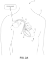
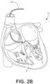
- FIGS. 2A-2B are conceptual diagrams illustrating one example therapy system 10 that may be used to provide therapy to heart 12 of patient 14.
- Patient 14 ordinarily, but not necessarily, will be a human.
- Therapy system 10 includes IMD 16, which is coupled to leads 18, 20, 23 and programmer 24.
- IMD 16 may be, for example, an implantable pacemaker, cardioverter, and/or defibrillator that provides electrical signals to heart 12 via electrodes coupled to one or more of leads 18, 20, 23.
- IMD 16 include: a pacemaker with a medical lead, an implantable cardioverter-defibrillator (ICD), an intracardiac device, a leadless pacing device (LPD), a subcutaneous ICD (S-ICD), and a subcutaneous medical device (e.g., nerve stimulator, inserted monitoring device, etc.).
- ICD implantable cardioverter-defibrillator
- LPD leadless pacing device
- S-ICD subcutaneous ICD
- a subcutaneous medical device e.g., nerve stimulator, inserted monitoring device, etc.
- Cardiac conduction system pacing therapy can be performed by other leads.
- Another illustrative lead including two or more pacing electrodes, can be used to deliver multisite pacing pulses to the bundle of His or one or both bundle branches.
- Multisite pacing can be delivered simultaneously or sequentially, as described and shown by U.S. Patent Publication No. 2016/0339248 , filed on April 21, 2016, entitled EFFICIENT DELIVERY OF MULTI-SITE PACING, the disclosure of which is incorporated by reference in its entirety.
- Delivering multisite pacing pulses may include delivering pacing pulses to a first tissue site and a second tissue site through first and second pacing electrodes, respectively, all of which may occur within the same cardiac cycle.
- a single lead including two (or more) pacing electrodes (e.g., cathodes) may deliver cathode pacing outputs at two separate locations (e.g., left and right bundle branches), so both bundle branches can be excited at the same time.
- pacing electrodes e.g., cathodes
- cathode pacing outputs may deliver cathode pacing outputs at two separate locations (e.g., left and right bundle branches), so both bundle branches can be excited at the same time.
- IMD 16 may include one, two, or more electrodes located in one or more bundle branches configured for bundle branch pacing.
- IMD 16 may be an intracardiac pacemaker or leadless pacing device (LPD).
- a leadless device refers to a device being free of a lead extending out of patient's heart 12.
- a leadless device may have a lead that does not extend from outside of the patient's heart to inside of the patient's heart.
- Some leadless devices may be introduced through a vein, but once implanted, the devices are free of, or may not include, any transvenous lead and may be configured to provide cardiac therapy without using any transvenous lead.
- an LPD for bundle pacing does not use a lead to operably connect to an electrode disposed proximate to the septum when a housing of the device is positioned in the atrium.
- a leadless electrode may be leadlessly coupled to the housing of the medical device without using a lead between the electrode and the housing.
- IMD 16 may sense electrical signals attendant to the depolarization and repolarization of heart 12 via electrodes (not shown in FIGS. 2A-B ) coupled to at least one of leads 18, 20, 23. In some examples, IMD 16 provides pacing pulses to heart 12 based on the electrical signals sensed within heart 12. The configurations of electrodes used by IMD 16 for sensing and pacing may be unipolar or bipolar. IMD 16 may also provide defibrillation therapy and/or cardioversion therapy via electrodes located on at least one of leads 18, 20, 23. IMD 16 may detect arrhythmia of heart 12, such as fibrillation of ventricles 28 and 32, and deliver defibrillation therapy to heart 12 in the form of electrical pulses.
- IMD 16 may be programmed to deliver a progression of therapies, e.g., pulses with increasing energy levels, until a fibrillation of heart 12 is stopped. IMD 16 may detect fibrillation employing one or more fibrillation detection techniques known in the art.
- programmer 24 may be a handheld computing device or a computer workstation or a mobile phone.
- Programmer 24 may include a user interface that receives input from a user.
- the user interface may include, for example, a keypad and a display, which may for example, be a cathode ray tube (CRT) display, a liquid crystal display (LCD) or light emitting diode (LED) display.
- the keypad may take the form of an alphanumeric keypad or a reduced set of keys associated with particular functions.
- Programmer 24 can additionally or alternatively include a peripheral pointing device, such as a mouse, via which a user may interact with the user interface.
- a display of programmer 24 may include a touch screen display, and a user may interact with programmer 24 via the display. Through the graphical user interface on programmer 24, a user may select one or more optimized parameters.
- various pacing settings may be adjusted, or configured, based on various sensed signals.
- various near-field and far-field signals may be sensed by one or more electrodes of the IMD 16 and/or other devices operatively coupled thereto.
- Vp to QRS end or offset within a near-field or far-field signal may be used to adjust or configure the AV delay of cardiac conduction system pacing therapy.
- QRS within a near-field or far-field signal may be used to adjust or configure the VV delay between cardiac conduction system pacing therapy and traditional left ventricular pacing therapy.
- QRS complexes may be detected using near field and/or far-field electrical signals.
- the far-field electrical signals may be sensed in a far-field electrogram (EGM) monitored by IMD 16 and a corresponding lead or a separate device, such as a subcutaneously implanted device.
- QRS duration is the time from which the Q wave is detected until the S wave ends.
- far-field electrical signal refers to the result of measuring cardiac activity using a sensor, or electrode, positioned outside of an area of interest.
- an ECG signal measured from an electrode positioned outside of the patient's heart is one example of a far-field electrical signal of the patient's heart.
- a far-field electrical signal representing electrical activity of a chamber of the patient's heart may be measured from a sensor, or electrode, positioned in an adjacent chamber.
- R-wave timing is the time in which QRS is detected. Typically, R-wave timing includes using the maximal first derivative of an R-wave upstroke (or the time of the maximal R-wave value). R-wave timing is also used in the device marker channel to indicate the time of the R-wave or the time of ventricular activation.
- Pacing-RV sensing or pacing-LV sensing is the time interval from the pacing (or pacing artifact) to the time of RV or LV sensing. For example, if pacing-RV sensing is much longer than pacing-LV sensing, this may indicate that the LV activation is occurring much earlier than RV activation (so pacing-RV sensing is longer), then RV pacing may be delivered in synchronization with bundle pacing, so RV and LV activation can occur approximately at the same time.
- a user may interact with programmer 24 to communicate with IMD 16.
- the user may interact with programmer 24 to retrieve physiological or diagnostic information from IMD 16.
- One illustrative IMD 16 is described in the Medtronic AMPLIA MRITM CRT-D SURESCAN TM DTMB2D1 manual, which is incorporated by reference in its entirety.
- a user may also interact with programmer 24 to program IMD 16, e.g., select values for operational parameters of the IMD.
- IMD 16 and programmer 24 may communicate via wireless communication using any techniques known in the art. Examples of communication techniques may include, for example, low frequency or radiofrequency (RF) telemetry, but other techniques are also contemplated.
- programmer 24 may include a programming head that may be placed proximate to the patient's body near the IMD 16 implant site in order to improve the quality or security of communication between IMD 16 and programmer 24.
- Each of the leads 18, 20, 23 includes an elongated, insulative lead body, which may carry any number of concentric coiled conductors separated from one another by tubular, insulative sheaths.
- an optional pressure sensor 38 and bipolar electrodes 40 and 42 are located proximate to a distal end of lead 18.
- bipolar electrodes 44 and 46 are located proximate to a distal end of lead 20 and bipolar electrodes 48 and 50 are located proximate to a distal end of lead 23.
- pressure sensor 38 is disposed in right ventricle 28. Pressure sensor 38 may respond to an absolute pressure inside right ventricle 28, and may be, for example, a capacitive or piezoelectric absolute pressure sensor.
- pressure sensor 38 may be positioned within other regions of heart 12 and may monitor pressure within one or more of the other regions of heart 12, or pressure sensor 38 may be positioned elsewhere within or proximate to the cardiovascular system of patient 14 to monitor cardiovascular pressure associated with mechanical contraction of the heart.
- a pressure sensor in the pulmonary artery can be used that is in communication with IMD 16.
- Electrodes 40, 44 and 48 may take the form of ring electrodes, and electrodes 42, 46 and 50 may take the form of extendable and/or fixed helix tip electrodes mounted within insulative electrode heads 52, 54 and 56, respectively.
- Each of electrodes 40, 42, 44, 46, 48 and 50 may be electrically coupled to a respective one of the coiled conductors within the lead body of its associated lead 18, 20, 23, and thereby coupled to respective ones of the electrical contacts on the proximal end of leads 18, 20 23.
- Electrodes 40, 42, 44, 46, 48 and 50 may sense electrical signals attendant to the depolarization and repolarization of heart 12. The electrical signals are conducted to IMD 16 via the respective leads 18, 20, 23. In some examples, IMD 16 also delivers pacing pulses via electrodes 40, 42, 44, 46, 48, 50 to cause depolarization of cardiac tissue of heart 12. In some examples, as illustrated in FIGS. 3A-B , IMD 16 includes one or more housing electrodes, such as housing electrode 58, which may be formed integrally with an outer surface of hermetically-sealed housing 60 of IMD 16 or otherwise coupled to housing 60. In some examples, housing electrode 58 may be defined by an uninsulated portion of an outward facing portion of housing 60 of IMD 16.
- housing electrode 58 may be defined by an uninsulated portion of an outward facing portion of housing 60 of IMD 16.
- Electrode 50 may be used for pacing and/or sensing of the His bundle or bundle branch tissue. Other divisions between insulated and uninsulated portions of housing 60 may be employed to define two or more housing electrodes.
- housing electrode 58 includes substantially all of housing 60. Any of the electrodes 40, 42, 44, 46, 48 and 50 may be used for unipolar sensing or pacing in combination with housing electrode 58 or for bipolar sensing with two electrodes in the same pacing lead.
- housing 60 may enclose a stimulation generator (see FIG. 5 ) that generates cardiac pacing pulses and defibrillation or cardioversion shocks, as well as a sensing module for monitoring the patient's heart rhythm.
- Electrodes 18, 20, 23 may also include elongated electrodes 62, 64, 66, respectively, which may take the form of a coil.
- IMD 16 may deliver defibrillation shocks to heart 12 via any combination of elongated electrodes 62, 64, 66, and housing electrode 58. Electrodes 58, 62, 64, 66 may also be used to deliver cardioversion pulses to heart 12. Electrodes 62, 64, 66 may be fabricated from any suitable electrically conductive material, such as, but not limited to, platinum, platinum alloy or other materials known to be usable in implantable defibrillation electrodes.
- Pressure sensor 38 may be coupled to one or more coiled conductors within lead 18. In FIG. 3A , pressure sensor 38 is located more distally on lead 18 than elongated electrode 62. In other examples, pressure sensor 38 may be positioned more proximally than elongated electrode 62, rather than distal to electrode 62. Further, pressure sensor 38 may be coupled to another one of the leads 20, 23 in other examples, or to a lead other than leads 18, 20, 23 carrying stimulation and sense electrodes. In addition, in some examples, pressure sensor 38 may be self-contained device that is implanted within heart 12, such as within the septum separating right ventricle 28 from left ventricle 32, or the septum separating right atrium 26 from left atrium 33. In such an example, pressure sensor 38 may wirelessly communicate with IMD 16.
- FIG. 3B shows IMD 16 coupled to leads 18, 20, 22, 23.
- Right atrial (RA) lead 22 may extend through one or more veins and the vena cava, and into the right atrium 26 of heart 12.
- RA lead 22 may be connected to triple chamber IMD 16, e.g., using a Y-adaptor.
- IMD 16 may be used for cardiac rhythm therapy and defibrillation or cardioversion therapy (CRT-D).
- RA lead 22 may include electrodes that are the same or similar to the electrodes of lead 18, 20, 23, such as ring electrodes 40, 44 and 48, extendable helix tip electrodes 42, 46 and 50, and/or elongated electrodes 62, 64, 66, in the form of a coil.
- therapy system 10 illustrated in FIGS. 2A-4 are merely examples.
- a therapy system may include epicardial leads and/or patch electrodes instead of or in addition to the transvenous leads 18, 20, 22 and/or cardiac conduction system pacing lead 23 illustrated in FIGS. 2A-4 or other configurations shown or described herein or incorporated by reference.
- IMD 16 need not be implanted within patient 14. In examples in which IMD 16 is not implanted in patient 14, IMD 16 may deliver defibrillation shocks and other therapies to heart 12 via percutaneous leads that extend through the skin of patient 14 to a variety of positions within or outside of heart 12.
- therapy systems may include any suitable number of leads coupled to IMD 16, and each of the leads may extend to any location within or proximate to heart 12.
- therapy systems may include three transvenous leads located as illustrated in FIGS. 2A-4 , and an additional lead located within or proximate to left atrium 33 ( FIG. 1 ).
- therapy systems may include a single lead that extends from IMD 16 into right atrium 26 or right ventricle 28, or two leads that extend into a respective one of right ventricle 28 and right atrium 26. An example of this type of therapy system is shown in FIGS. 3A-3B .
- an IS-1 connector may be used in conjunction with Y-adaptor 25 extending from the RA port of the connector.
- the Y-adaptor allows two separate leads-e.g., right atrial lead and the bundle pacing bundle lead--to extend from the two separate legs of the "Y shape" while the single leg is inserted into connector block 34 on IMD 16.
- FIG. 4 is a conceptual diagram illustrating another example of therapy system 70.
- Therapy system 70 shown in FIG. 4 may be useful for providing defibrillation and pacing pulses to heart 12.
- Therapy system 70 is similar to therapy system 10 of FIGS. 2A-B or 3A-B , but includes two leads 18, 23, rather than three leads.
- Therapy system 70 may utilize an IMD 16 configured to deliver, or perform, dual chamber pacing. Leads 18, 23 are implanted within right ventricle 28 and right atrium 26 to pace one or more portions of the cardiac conduction system such as the His bundle or one or both bundle branches, respectively.
- Cardiac conduction system pacing lead 23 may be in the form of a helix (also referred to as a helical electrode) may be positioned proximate to, near, adjacent to, or in, area or portions of the cardiac conduction system such as, e.g., ventricular septum, triangle of Koch, the His bundle, left right bundle branch tissues, and/or right bundle branch tissue.
- Cardiac conduction system pacing lead 23 may be configured as a bipolar lead or as a quadripolar lead that may be used with a pacemaker device, a CRT-P device or a CRT-ICD.
- FIG. 5 is a functional block diagram of one example configuration of IMD 16, which includes processor 80, memory 82, stimulation generator 84 (e.g., electrical pulse generator or signal generating circuit), sensing module 86 (e.g., sensing circuit), telemetry module 88, and power source 90.
- IMD 16 includes processor 80, memory 82, stimulation generator 84 (e.g., electrical pulse generator or signal generating circuit), sensing module 86 (e.g., sensing circuit), telemetry module 88, and power source 90.
- One or more components of IMD 16, such as processor 80, may be contained within a housing of IMD 16 (e.g., within a housing of a pacemaker).
- Telemetry module 88, sensing module 86, or both telemetry module 88 and sensing module 86 may be included in a communication interface.
- Memory 82 includes computer-readable instructions that, when executed by processor 80, cause IMD 16 and processor 80 to perform various functions attributed to IMD 16 and processor 80 herein.
- Memory 82 may include any volatile, non-volatile, magnetic, optical, or electrical media, such as a random-access memory (RAM), read-only memory (ROM), non-volatile RAM (NVRAM), electrically-erasable programmable ROM (EEPROM), flash memory, or any other digital media.
- RAM random-access memory
- ROM read-only memory
- NVRAM non-volatile RAM
- EEPROM electrically-erasable programmable ROM
- flash memory or any other digital media.
- Processor 80 may include any one or more of a microprocessor, a controller, a digital signal processor (DSP), an application specific integrated circuit (ASIC), a field-programmable gate array (FPGA), or equivalent discrete or integrated logic circuitry.
- processor 80 may include multiple components, such as any combination of one or more microprocessors, one or more controllers, one or more DSPs, one or more ASICs, or one or more FPGAs, as well as other discrete or integrated logic circuitry.
- the functions attributed to processor 80 herein may be embodied as software, firmware, hardware or any combination thereof.
- Processor 80 controls stimulation generator 84 to deliver stimulation therapy to heart 12 according to a selected one or more of therapy programs (e.g., optimization of the AV delay, VV delay, VV delay etc.), which may be stored in memory 82. Specifically, processor 80 may control stimulation generator 84 to deliver electrical pulses with amplitudes, pulse widths, frequency, or electrode polarities specified by the selected one or more therapy programs.
- therapy programs e.g., optimization of the AV delay, VV delay, VV delay etc.
- RA lead 22 may be operably coupled to electrode 61, which may be used to monitor or pace the RA.
- Stimulation generator 84 may be electrically coupled to electrodes 40, 42, 44, 46, 48, 50, 58, 61, 62, 64, and 66, e.g., via conductors of respective lead 18, 20, 22, 23 or, in the case of housing electrode 58, via an electrical conductor disposed within housing 60 of IMD 16.
- Stimulation generator 84 may be configured to generate and deliver electrical stimulation therapy to heart 12. For example, stimulation generator 84 may deliver defibrillation shocks to heart 12 via at least two of electrodes 58, 62, 64, 66.
- Stimulation generator 84 may deliver pacing pulses via ring electrodes 40, 44, 48 coupled to leads 18, 20, 23, respectively, and/or helical electrodes 42, 46, and 50 of leads 18, 20, or 23, respectively.
- Cardiac conduction system pacing therapy can be delivered through cardiac conduction system lead 23 that is connected to an atrial, RV, or LV connection port of connector block 34.
- the cardiac conduction system pacing therapy can be delivered through leads 18 and/or 23.
- stimulation generator 84 delivers pacing, cardioversion, or defibrillation stimulation in the form of electrical pulses.
- stimulation generator 84 may deliver one or more of these types of stimulation in the form of other signals, such as sine waves, square waves, or other substantially continuous time signals.
- Stimulation generator 84 may include a switch module and processor 80 may use the switch module to select, e.g., via a data/address bus, which of the available electrodes are used to deliver defibrillation shocks or pacing pulses.
- the switch module may include a switch array, switch matrix, multiplexer, or any other type of switching device suitable to selectively couple stimulation energy to selected electrodes.
- Sensing module 86 monitors signals from at least one of electrodes 40, 42, 44, 46, 48, 50, 58, 61, 62, 64 or 66 in order to monitor electrical activity of heart 12, e.g., via electrical signals, such as electrocardiogram (ECG) signals and/or electrograms (EGMs). Sensing module 86 may also include a switch module to select which of the available electrodes are used to sense the heart activity. In some examples, processor 80 may select the electrodes that function as sense electrodes via the switch module within sensing module 86, e.g., by providing signals via a data/address bus. In some examples, sensing module 86 includes one or more sensing channels, each of which may include an amplifier. In response to the signals from processor 80, the switch module may couple the outputs from the selected electrodes to one of the sensing channels.
- one channel of sensing module 86 may include an R-wave amplifier that receives signals from electrodes 40, 42, which are used for pacing and sensing in right ventricle 28 of heart 12.
- Another channel may include another R-wave amplifier that receives signals from electrodes 44, 46, which are used for pacing and sensing proximate to left ventricle 32 of heart 12.
- the R-wave amplifiers may take the form of an automatic gain-controlled amplifier that provides an adjustable sensing threshold as a function of the measured R-wave amplitude of the heart rhythm.
- one channel of sensing module 86 may include a P-wave amplifier that receives signals from electrodes 48, 50, which are used for pacing and sensing in right atrium 26 of heart 12.
- the P-wave amplifier may take the form of an automatic gain-controlled amplifier that provides an adjustable sensing threshold as a function of the measured P-wave amplitude of the heart rhythm. Examples of R-wave and P-wave amplifiers are described in U.S. Patent No. 5,117,824 to Keimel et al., which issued on June 2, 1992 and is entitled, "APPARATUS FOR MONITORING ELECTRICAL PHYSIOLOGIC SIGNALS.” Other amplifiers may also be used.
- one or more of the sensing channels of sensing module 86 may be selectively coupled to housing electrode 58, or elongated electrodes 62, 64, or 66, with or instead of one or more of electrodes 40, 42, 44, 46, 48 or 50, e.g., for unipolar sensing of R-waves or P-waves in any of chambers 26, 28, or 32 of heart 12.
- sensing module 86 includes a channel that includes an amplifier with a relatively wider pass band than the R-wave or P-wave amplifiers or a high-resolution amplifier with relatively narrow-pass band for His bundle or bundle branch potential recording. Signals from the selected sensing electrodes that are selected for coupling to this wide-band amplifier may be provided to a multiplexer, and thereafter converted to multi-bit digital signals by an analog-to-digital converter for storage in memory 82 as an electrogram (EGM). In some examples, the storage of such EGMs in memory 82 may be under the control of a direct memory access circuit. Processor 80 may employ digital signal analysis techniques to characterize the digitized signals stored in memory 82 to detect and classify the patient's heart rhythm from the electrical signals. Processor 80 may detect and classify the heart rhythm of patient 14 by employing any of the numerous signal processing methodologies known in the art.
- processor 80 may include pacer timing and control module, which may be embodied as hardware, firmware, software, or any combination thereof.
- the pacer timing and control module may include a dedicated hardware circuit, such as an ASIC, separate from other processor 80 components, such as a microprocessor, or a software module executed by a component of processor 80, which may be a microprocessor or ASIC.
- the pacer timing and control module may include programmable counters which control the basic time intervals associated with DDD, VVI, DVI, VDD, AAI, DDI, DDDR, VVIR, DVIR, VDDR, AAIR, DDIR and other modes of single and dual chamber pacing.
- D may indicate dual chamber
- V may indicate a ventricle
- I may indicate inhibited pacing (e.g., no pacing)
- A may indicate an atrium.
- the first letter in the pacing mode may indicate the chamber that is paced
- the second letter may indicate the chamber in which an electrical signal is sensed
- the third letter may indicate the chamber in which the response to sensing is provided.
- Intervals defined by the pacer timing and control module may include atrial and ventricular pacing escape intervals, refractory periods during which sensed P-waves and R-waves are ineffective to restart timing of the escape intervals, and the pulse widths of the pacing pulses.
- the pace timing and control module may define a blanking time period and provide signals from sensing module 86 to blank one or more channels, e.g., amplifiers, for a period during and after delivery of electrical stimulation to heart 12. The durations of these intervals may be determined by processor 80 in response to stored data in memory 82.
- the pacer timing and control module may also determine the amplitude of the cardiac pacing pulses.
- escape interval counters within the pacer timing/control module may be reset upon sensing of R-waves and P-waves.
- Stimulation generator 84 may include pacer output circuits that are coupled, e.g., selectively by a switching module, to any combination of electrodes 40, 42, 44, 46, 48, 50, 58, 61, 62, or 66 appropriate for delivery of a bipolar or unipolar pacing pulse to one of the chambers of heart 12.
- Processor 80 may reset the escape interval counters upon the generation of pacing pulses by stimulation generator 84, and thereby control the basic timing of cardiac pacing functions, including anti-tachyarrhythmia pacing.
- processor 80 may operate as an interrupt driven device, and is responsive to interrupts from pacer timing and control module, where the interrupts may correspond to the occurrences of sensed P-waves and R-waves and the generation of cardiac pacing pulses. Any necessary mathematical calculations to be performed by processor 80 and any updating of the values or intervals controlled by the pacer timing and control module of processor 80 may take place following such interrupts.
- a portion of memory 82 may be configured as a plurality of recirculating buffers, capable of holding series of measured intervals, which may be analyzed by processor 80 in response to the occurrence of a pace or sense interrupt to determine whether the patient's heart 12 is presently exhibiting atrial or ventricular tachyarrhythmia.
- Telemetry module 88 includes any suitable hardware, firmware, software or any combination thereof for communicating with another device, such as programmer 24 ( FIG. 2A ). Under the control of processor 80, telemetry module 88 may receive downlink telemetry from and send uplink telemetry to programmer 24 with the aid of an antenna, which may be internal and/or external. Processor 80 may provide the data to be uplinked to programmer 24 and the control signals for the telemetry circuit within telemetry module 88, e.g., via an address/data bus. In some examples, telemetry module 88 may provide received data to processor 80 via a multiplexer.
- IMD 16 The various components of IMD 16 are coupled to power source 90, which may include a rechargeable or non-rechargeable battery.
- a non-rechargeable battery may be selected to last for several years, while a rechargeable battery may be inductively charged from an external device, e.g., on a daily or weekly basis.
- the illustrative devices and methods described herein may provide adaptive cardiac conduction system pacing therapy.
- the illustrative adaptive cardiac conduction system pacing therapy may provide configuration of the timing of the cardiac conduction system pacing as well as timing for traditional left ventricular pacing when used in conjunction with the cardiac conduction system pacing therapy. Additionally, the illustrative adaptive cardiac conduction pacing therapy may also provide switching from cardiac conduction system pacing therapy only to a combination of cardiac conduction system pacing therapy and traditional left ventricular pacing therapy.
- FIG. 6 An illustrative method 200 of adaptive cardiac conduction system pacing therapy that may be utilized by the devices of FIGS. 1-5 is depicted in FIG. 6 .
- the method 200 may determine a paced AV delay 210 for use in delivery of cardiac conduction system pacing therapy using the cardiac conduction system electrode.
- the paced AV delay is a time period between a sensed or paced atrial event (e.g., depolarization of the atrium, p-wave in an electrocardiogram, etc.) and delivery of cardiac conduction system pacing therapy (e.g., delivery of a pacing pulse to the cardiac conduction system).
- the paced AV delay may be determined using various illustrative processes.
- One illustrative process of determining AV delay 210 of the method of FIG. 6 is depicted in FIG. 7 .
- the process 210 of FIG. 7 may include measuring an intrinsic AV delay using a cardiac conduction system electrode 212.
- the cardiac conduction system electrode is the electrode configured to deliver cardiac conduction system (for example, an electrode positioned on cardiac conduction system lead 23 as described herein).
- the intrinsic AV delay is a time period between a sensed intrinsic, or naturally-occurring, atrial event (e.g., depolarization of the atrium, p-wave in an electrocardiogram, etc.) and a sensed intrinsic, or naturally-occurring, ventricular event (e.g., depolarization of the left ventricle or both ventricles, r-wave in an electrocardiogram, etc.).
- atrial event e.g., depolarization of the atrium, p-wave in an electrocardiogram, etc.
- ventricular event e.g., depolarization of the left ventricle or both ventricles, r-wave in an electrocardiogram, etc.
- the measured intrinsic AV delay may be used when testing various paced AV delays.
- the process 210 may include delivering cardiac conduction system pacing therapy to the patient's cardiac conduction system using the cardiac conduction system electrode at a plurality of different paced AV delays that are less than the intrinsic AV delay 214.
- the plurality of different paced AV delays may be based on various percentages of the intrinsic AV delay. Each various percentage may be referred to an AV delay percentage.
- the plurality of different paced AV delays may be between about 20% of the intrinsic AV delay and about 90% of the intrinsic AV delay.
- the plurality of different paced AV delays may include a range of paced AV delays based on different AV delay percentages spaced 5% or more apart from one another.
- the plurality of different paced AV delays may include 20% of the intrinsic AV delay, 30% of the intrinsic AV delay, 40% of the intrinsic AV delay, 50% of the intrinsic AV delay, 60% of the intrinsic AV delay, 70% of the intrinsic AV delay, and 80% of the intrinsic AV delay.
- the cardiac conduction system pacing therapy may be delivered for one or a plurality of cardiac cycles at each different paced AV delay (or each different AV delay percentage) to, e.g., provide an appropriate sample size of data to evaluate.
- the process 210 may further monitor far-field electrical activity 216 during delivery of the cardiac conduction system pacing therapy.
- the far-field electrical activity may be monitored by any electrode positioned outside of the cardiac conduction system pacing therapy area of interest.
- the far-field electrical activity may be monitored by a ring electrode positioned on a left ventricular lead located in the coronary sinus.
- the far-field electrical activity may be monitored by an external electrode disposed on the skin of the patient's torso.
- a paced AV delay of the plurality of different paced AV delays may be selected 218 based on the far-field electrical activity monitored during the delivery of cardiac conduction system pacing therapy at the plurality of different paced AV delays. More specifically, one or more metrics may be derived or determined from the far-field electrical activity that may be used to determine the most effective or optimal paced AV delay for the cardiac conduction system pacing therapy. In at least one embodiment, a time period between the delivery of the cardiac conduction system pacing therapy and an end of ventricular depolarization (e.g., QRS offset) may be determined for each of the plurality of different paced AV delays. Then, the paced AV delay or AV delay percentage providing the shortest time period between the delivery of the cardiac conduction system pacing therapy and an end of ventricular depolarization may be selected.
- QRS offset end of ventricular depolarization
- the selected paced AV delay may be percentage of the intrinsic AV delay, which may be referred to as an AV delay percentage.
- the selected AV delay percentage may be 70% of the intrinsic AV delay.
- the intrinsic AV delay may be measured periodically by halting any cardiac pacing therapy, and the paced AV delay may be adjusted accordingly according the selected AV delay percentage.
- the process 210 may result in a selected AV delay for delivery of cardiac conduction system pacing therapy.
- the method 200 may further include determining a VV delay for cardiac conduction system and left ventricular pacing therapy 220.
- the VV delay may be the time period between the delivery of the cardiac conduction system pacing therapy and the delivery of the left ventricular pacing therapy.
- the cardiac conduction system pacing therapy and left ventricular pacing therapy may be delivered 222 for one or a plurality of cardiac cycles at each different paced VV delay to, e.g., provide an appropriate sample size of data to evaluate.
- the process 220 may further monitoring far-field electrical activity 224 during delivery of the cardiac conduction system and left ventricular pacing therapy.
- the far-field electrical activity may be monitored by any electrode positioned outside of the cardiac conduction system pacing therapy area of interest.
- the far-field electrical activity may be monitored by a ring electrode positioned on a left ventricular lead located in the coronary sinus.
- the far-field electrical activity may be monitored by an external electrode disposed on the skin of the patient's torso.
- the time period between the earliest pacing e.g., either cardiac conduction system pacing therapy or left ventricular pacing therapy depending on the present VV delay
- an end of ventricular depolarization e.g., QRS duration, the time period between QRS onset and QRS offset, etc.
- QRS duration the time period between QRS onset and QRS offset, etc.
- the process 220 may result in a selected VV delay for delivery of cardiac conduction system and left ventricular pacing therapy when used in combination.
- the method 200 may then be configured to deliver cardiac conduction system pacing therapy and combined cardiac conduction system and left ventricular pacing therapy, if needed.
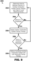
- the method 200 may initiate or begin delivery of cardiac conduction system pacing therapy alone 230 and monitoring local electrical activity of the patient using a left ventricular electrode 240 during the delivery of cardiac conduction system pacing therapy.
- the local electrical activity may be used to determine whether to switch to combined cardiac conduction system and left ventricular pacing therapy 250.
- various metrics may be derived or generated from the local electrical activity, which may then be used to determine whether to switch to combined cardiac conduction system and left ventricular pacing therapy 250.
- the process 250 includes determining an interval between the delivery of cardiac conduction system pacing therapy and a peak in the local monitored local activity 252 and then comparing the interval to a threshold value 254.
- the threshold value may be between about 25 ms and about 75 ms. In at least one embodiment, the threshold value is 50 ms. In other embodiments, the threshold value may be greater than or equal to 25 ms, greater than or equal to 35 ms, greater than or equal to 45 ms, greater than or equal to 55 ms, etc.
- the cardiac conduction system pacing therapy may be less than optimal or most effective, and thus may be adjusted and/or may benefit from the additional of left ventricular pacing therapy. If the measured interval is less than the threshold value, then it may be determined that the cardiac conduction system pacing therapy is effective and the process may return to monitoring the local electrical activity 252.
- the process 250 may continue looping to adjust the output parameter until the adjustments are exhausted 258.
- the pacing output parameter adjustments may be exhausted when the pacing output cannot be further adjusted or increased.
- the cardiac conduction system pacing output may be exhausted when it is at its upper, or maximum, limit.
- the process 250 may proceed to delivering combined cardiac conduction system and left ventricular pacing therapy 259 according to the previously-determined AV delay and VV delay.
- the process 250 may switch from cardiac conduction system pacing therapy only to cardiac conduction system pacing therapy being used in conjunction with left ventricular pacing therapy.
- the illustrative devices and methods described herein may be further configured to determine whether cardiac conduction system pacing therapy being delivered to the patient's cardiac conduction system has selectively or non-selectively captured the patient's cardiac conduction system.
- Cardiac conduction system pacing therapy having selective capture of the cardiac conduction system may be defined as pacing therapy that delivers pacing therapy only to the cardiac conduction system and that does not deliver pacing therapy directly to myocardial or muscular cardiac tissue. In other words, selective cardiac conduction system pacing therapy paces the cardiac conduction system alone.
- Cardiac conduction system pacing therapy having non-selective capture of the cardiac conduction system may be defined as pacing therapy that delivers pacing therapy to the cardiac conduction system and also directly to the myocardial or muscular cardiac tissue.
- non-selective cardiac conduction system pacing therapy paces both the cardiac conduction system and myocardial or muscular cardiac tissue.
- the illustrative devices and methods, using a near-field signal, may be able to determine whether the delivered cardiac conduction system pacing therapy is selective or non-selective, which may be helpful in delivery of effective cardiac therapy to a patient.
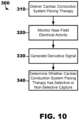
- the method 300 may include delivering cardiac conduction system pacing therapy 310 using, for example, one of the illustrative devices described herein with respect to FIGS. 1-5 , and monitoring near-field electrical activity 320 during delivery of the cardiac conduction system pacing therapy.
- the near-field electrical activity may be monitored via one or more implantable electrodes that are located proximate the left bundle branch.
- the sensing time period may follow a blanking time period following the delivery of the cardiac conduction system pacing therapy.
- the blanking time period may be between about 5 ms and about 30 ms. In at least one embodiment, the blanking time period is 20 ms. In other embodiments, the blanking time period may be greater than or equal to 5 ms, greater than or equal to 10 ms, greater than or equal to 15 ms, etc. and/or less than or equal to 30 ms, less than or equal to 25 ms, less than or equal to 17 ms, etc.
- a blanking time period which may be 20 ms, may delay the measuring or monitoring of the near-field electrical activity that may then be measured or monitored for a sensing time period, which may be 50 ms.
- a change event may generally be described as an event where the derivative signal changes sign from positive-to-negative or positive-to-negative.
- a minimum change threshold may be used such as, e.g., 0.1 Volts.
- a change event may be counted or determined for every sign change that is greater than 0.1 Volt within the derivative signal over the sensing period.
- the minimum change threshold in this example is 0.1 Volts
- the minimum change threshold may be less than 0.1 Volts or greater than 0.1 Volts.
- the minimum change threshold may be between about 0.05 Volts and about 0.4 Volts.
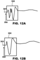
- a left bunch branch electrocardiogram 351 showing selective cardiac conduction system capture is depicted in FIG 12A . As shown, more than 5 change events have occurred within the sensing time period 352 following the cardiac conduction system pacing therapy 350 thereby indicating selective capture of the cardiac conduction system.
- a left bunch branch electrocardiogram 353 showing non-selective cardiac conduction system capture is depicted in FIG 12B . As shown, less than or equal to 5 change events have occurred within the sensing time period 352 following the cardiac conduction system pacing therapy 350 thereby indicating non-selective capture of the cardiac conduction system.
- a single chamber, dual chamber, or triple chamber pacemakers (e.g., CRT-P) or ICDs (e.g., CRT-D) devices can be used to implement the illustrative methods described herein.
- the described techniques may be implemented in hardware, software, firmware, or any combination thereof. If implemented in software, the functions may be stored as one or more instructions or code on a computer-readable medium and executed by a hardware-based processing unit.
- Computer-readable media may include non-transitory computer-readable media, which corresponds to a tangible medium such as data storage media (e.g., RAM, ROM, EEPROM, flash memory, or any other medium that can be used to store desired program code in the form of instructions or data structures and that can be accessed by a computer).
- processors such as one or more digital signal processors (DSPs), general purpose microprocessors, application specific integrated circuits (ASICs), field programmable logic arrays (FPGAs), or other equivalent integrated or discrete logic circuitry.
- DSPs digital signal processors
- ASICs application specific integrated circuits
- FPGAs field programmable logic arrays
- processors may refer to any of the foregoing structure or any other physical structure suitable for implementation of the described techniques. Also, the techniques could be fully implemented in one or more circuits or logic elements.
- Coupled refers to elements being attached to each other either directly (in direct contact with each other) or indirectly (having one or more elements between and attaching the two elements). Either term may be modified by "operatively” and “operably,” which may be used interchangeably, to describe that the coupling or connection is configured to allow the components to interact to carry out at least some functionality (for example, a mobile user device may be operatively coupled to a cellular network transmit data to or receive data therefrom).
- references to "one embodiment,” “an embodiment,” “certain embodiments,” or “some embodiments,” etc. means that a particular feature, configuration, composition, or characteristic described in connection with the embodiment is included in at least one embodiment of the disclosure. Thus, the appearances of such phrases in various places throughout are not necessarily referring to the same embodiment of the disclosure. Furthermore, the particular features, configurations, compositions, or characteristics may be combined in any suitable manner in one or more embodiments.
- phrases "at least one of,” “comprises at least one of,” and “one or more of” followed by a list refers to any one of the items in the list and any combination of two or more items in the list.
Landscapes
- Health & Medical Sciences (AREA)
- Heart & Thoracic Surgery (AREA)
- Cardiology (AREA)
- Life Sciences & Earth Sciences (AREA)
- Nuclear Medicine, Radiotherapy & Molecular Imaging (AREA)
- Biomedical Technology (AREA)
- Engineering & Computer Science (AREA)
- Radiology & Medical Imaging (AREA)
- Animal Behavior & Ethology (AREA)
- General Health & Medical Sciences (AREA)
- Public Health (AREA)
- Veterinary Medicine (AREA)
- Biophysics (AREA)
- Physiology (AREA)
- Electrotherapy Devices (AREA)
Claims (8)
- Implantierbare medizinische Vorrichtung, umfassend:
eine Vielzahl von implantierbaren Elektroden zum Erfassen und Stimulieren des Herzens eines Patienten, wobei die Vielzahl von Elektroden umfasst:eine linksventrikuläre Elektrode (44, 46), die in der Nähe der linken Herzkammer des Patienten positionierbar ist; undeine Herzreizleitungssystemelektrode (50), die in der Nähe eines Abschnitts des Herzreizleitungssystems des Patienten positionierbar ist; undeine Recheneinrichtung, umfassend eine Verarbeitungsschaltlogik, wobei die Recheneinrichtung mit der Vielzahl von implantierbaren Elektroden betriebsmäßig gekoppelt ist, wobei die Rechenvorrichtung konfiguriert ist zum:Initiieren der Abgabe einer Stimulationstherapie des Herzreizleitungssystems an das Herzreizleitungssystem des Patienten unter Verwendung der Herzreizleitungssystemelektrode;Überwachen der lokalen elektrische Aktivität des Patienten unter Verwendung der linksventrikulären Elektrode während der Abgabe einer Stimulationstherapie des Herzreizleitungssystems unter Verwendung der Herzreizleitungssystemelektrode; undUmschalten auf die Abgabe sowohl einer Stimulationstherapie des Herzreizleitungssystems an das Herzreizleitungssystem des Patienten unter Verwendung der Herzreizleitungssystemelektrode als auch einer linksventrikulären Stimulationstherapie an die linke Herzkammer des Patienten unter Verwendung der linksventrikulären Elektrode als Reaktion auf die überwachte lokale elektrische Aktivität. - Vorrichtung nach Anspruch 1, wobei die Herzreizleitungssystemelektrode in der Nähe des His-Bündels des Patienten positionierbar ist, um dort eine Stimulationstherapie des Herzreizleitungssystems abzugeben.
- Vorrichtung nach einem der Ansprüche 1 bis 2, wobei die Herzreizleitungssystemelektrode in der Nähe des linken Bündelzweigbündels des Patienten positionierbar ist, um dort eine Stimulationstherapie des Herzreizleitungssystems abzugeben.
- Vorrichtung nach einem der Ansprüche 1 bis 3, wobei die Recheneinrichtung ferner konfiguriert ist, um ein Intervall zwischen der Abgabe der Stimulationstherapie des Herzreizleitungssystems und einem Spitzenwert der überwachten lokalen elektrischen Aktivität zu bestimmen, wobei das Umschalten auf die Abgabe sowohl der Stimulationstherapie des Herzreizleitungssystems an das Herzreizleitungssystem des Patienten unter Verwendung der Herzreizleitungssystemelektrode als auch einer linksventrikulären Stimulationstherapie an die linke Herzkammer des Patienten unter Verwendung der linksventrikulären Elektrode auf dem Intervall basiert ist.
- Vorrichtung nach Anspruch 4, wobei die Recheneinrichtung ferner konfiguriert ist, um einen Stimulationsausgangsparameter des Herzreizleitungssystems als Reaktion darauf anzupassen, dass das Intervall größer oder gleich einer Schwelle ist.
- Vorrichtung nach Anspruch 5, wobei die Schwelle kleiner als oder gleich 50 Millisekunden ist.
- Vorrichtung nach einem der Ansprüche 4 bis 6, wobei das Umschalten auf die Abgabe sowohl einer Stimulationstherapie des Herzreizleitungssystems als auch einer linksventrikulären Stimulationstherapie als Reaktion auf die überwachte lokale elektrische Aktivität das Umschalten auf die Abgabe sowohl einer Stimulationstherapie des Herzreizleitungssystems als auch einer linksventrikulären Stimulationstherapie als Reaktion darauf, dass das Intervall größer als oder gleich dem Schwellenwert ist, umfasst.
- Vorrichtung nach einem der Ansprüche 1 bis 7, wobei die Recheneinrichtung ferner konfiguriert ist zum:regelmäßigen Unterbrechen der Abgabe der Stimulationstherapie und Überwachen der intrinsischen elektrischen Aktivität des Patienten unter Verwendung der linksventrikulären Elektrode während der intrinsischen elektrischen Herzaktivierung; undBestimmen einer stimulierten AV-Verzögerung zur Verwendung bei der Abgabe einer Stimulationstherapie des Herzreizleitungssystems unter Verwendung der Herzreizleitungssystemelektrode basierend auf der überwachten intrinsischen elektrischen Aktivität, wobei die stimulierte AV-Verzögerung ein Zeitraum zwischen einem Vorhofereignis und der Abgabe einer Stimulationstherapie des Herzreizleitungssystems ist.
Applications Claiming Priority (4)
| Application Number | Priority Date | Filing Date | Title |
|---|---|---|---|
| US202063059466P | 2020-07-31 | 2020-07-31 | |
| US202063066521P | 2020-08-17 | 2020-08-17 | |
| US17/360,648 US11752347B2 (en) | 2020-07-31 | 2021-06-28 | Cardiac conduction system pacing |
| PCT/US2021/042940 WO2022026313A1 (en) | 2020-07-31 | 2021-07-23 | Cardiac conduction system pacing |
Publications (2)
| Publication Number | Publication Date |
|---|---|
| EP4188534A1 EP4188534A1 (de) | 2023-06-07 |
| EP4188534B1 true EP4188534B1 (de) | 2025-07-09 |
Family
ID=80002555
Family Applications (3)
| Application Number | Title | Priority Date | Filing Date |
|---|---|---|---|
| EP21756114.1A Pending EP4188532A1 (de) | 2020-07-31 | 2021-07-23 | Herzleitungssystem-pacing |
| EP21758860.7A Active EP4188534B1 (de) | 2020-07-31 | 2021-07-23 | Herzleitungssystem-pacing |
| EP21756115.8A Pending EP4188533A1 (de) | 2020-07-31 | 2021-07-23 | Herzleitungssystem-pacing |
Family Applications Before (1)
| Application Number | Title | Priority Date | Filing Date |
|---|---|---|---|
| EP21756114.1A Pending EP4188532A1 (de) | 2020-07-31 | 2021-07-23 | Herzleitungssystem-pacing |
Family Applications After (1)
| Application Number | Title | Priority Date | Filing Date |
|---|---|---|---|
| EP21756115.8A Pending EP4188533A1 (de) | 2020-07-31 | 2021-07-23 | Herzleitungssystem-pacing |
Country Status (4)
| Country | Link |
|---|---|
| US (2) | US11752347B2 (de) |
| EP (3) | EP4188532A1 (de) |
| CN (3) | CN116056754A (de) |
| WO (3) | WO2022026317A1 (de) |
Families Citing this family (4)
| Publication number | Priority date | Publication date | Assignee | Title |
|---|---|---|---|---|
| US20230381524A1 (en) * | 2022-05-31 | 2023-11-30 | Singular Medical (USA) Inc. | Systems and methods for cardiac conduction system |
| WO2024084319A1 (en) * | 2022-10-19 | 2024-04-25 | Medtronic, Inc. | Conduction system pacing control |
| US12508428B2 (en) | 2023-01-26 | 2025-12-30 | Medtronic, Inc. | Respiratory-based cardiac remodeling pacing therapy |
| WO2025108642A1 (en) * | 2023-11-22 | 2025-05-30 | Biotronik Se & Co. Kg | Implantable medical device for cardiac resynchronization therapy featuring an automatic adaptation of the stimulation parameters |
Family Cites Families (89)
| Publication number | Priority date | Publication date | Assignee | Title |
|---|---|---|---|---|
| US4374382A (en) | 1981-01-16 | 1983-02-15 | Medtronic, Inc. | Marker channel telemetry system for a medical device |
| US4624265A (en) | 1985-07-24 | 1986-11-25 | Ge. Sv. In. S.R.L. | Electro-catheter used in physiological cardiac stimulation simulative of the auriculo-ventricular sequence, featuring active engagement of the cardiac muscle |
| US5117824A (en) | 1990-11-14 | 1992-06-02 | Medtronic, Inc. | Apparatus for monitoring electrical physiologic signals |
| US5174286A (en) | 1990-12-07 | 1992-12-29 | Raul Chirife | Sensor for right ventricular and thoracic volumes using the trailing edge value of a generated pulse |
| US5545186A (en) | 1995-03-30 | 1996-08-13 | Medtronic, Inc. | Prioritized rule based method and apparatus for diagnosis and treatment of arrhythmias |
| US5800467A (en) | 1995-12-15 | 1998-09-01 | Pacesetter, Inc. | Cardio-synchronous impedance measurement system for an implantable stimulation device |
| EP0902707B1 (de) | 1996-05-14 | 2000-08-16 | Medtronic, Inc. | Sich auf prioritätsregeln beziehendes gerät für diagnose und behandlung von herzarhythmie |
| US5728140A (en) | 1996-06-17 | 1998-03-17 | Cardiac Pacemakers, Inc. | Method for evoking capture of left ventricle using transeptal pacing lead |
| US5964795A (en) | 1998-03-13 | 1999-10-12 | Medtronic, Inc. | Medical electrical lead |
| FR2802433B1 (fr) | 1999-12-17 | 2002-05-17 | Ela Medical Sa | Dispositif medical, implantable actif, notamment stimulateur cardiaque, defibrillateur et/ou cardiovecteur du type multisite comportant des moyens de resynchronisation des ventricules |
| US6609027B2 (en) | 2001-02-23 | 2003-08-19 | Pacesetter, Inc. | His Bundle sensing device and associated method |
| US6804555B2 (en) | 2001-06-29 | 2004-10-12 | Medtronic, Inc. | Multi-site ventricular pacing system measuring QRS duration |
| US6738674B2 (en) | 2001-07-25 | 2004-05-18 | Oscor Inc. | Implantable coronary sinus lead with mapping capabilities |
| US6711443B2 (en) | 2001-07-25 | 2004-03-23 | Oscor Inc. | Implantable coronary sinus lead and method of implant |
| US6718206B2 (en) | 2001-10-23 | 2004-04-06 | Medtronic, Inc. | Permanent atrial-his-ventricular sequential pacing |
| US6768923B2 (en) | 2001-12-05 | 2004-07-27 | Cardiac Pacemakers, Inc. | Apparatus and method for ventricular pacing triggered by detection of early ventricular excitation |
| AU2003223583A1 (en) | 2002-04-11 | 2003-10-27 | Transvascular, Inc. | Devices and methods for transluminal or transthoracic interstitial electrode placement |
| US20030199938A1 (en) | 2002-04-22 | 2003-10-23 | Karel Smits | Precise cardiac lead placement based on impedance measurements |
| US7164948B2 (en) | 2002-04-22 | 2007-01-16 | Medtronic, Inc. | Cardiac output measurement using dual oxygen sensors in right and left ventricles |
| US7177704B2 (en) | 2002-04-29 | 2007-02-13 | Medtronic, Inc. | Pacing method and apparatus |
| US7386351B2 (en) | 2002-04-30 | 2008-06-10 | Medtronic, Inc. | Method and apparatus for placing a coronary sinus/cardiac vein pacing and defibriliation lead with adjustable electrode spacing |
| US7151965B2 (en) | 2002-07-19 | 2006-12-19 | Oscor Inc. | Device and method for delivering cardiac leads |
| US6988007B1 (en) | 2002-08-13 | 2006-01-17 | Pacesetter, Inc. | Single pass telescoping cardiac lead for the left heart |
| US7317950B2 (en) | 2002-11-16 | 2008-01-08 | The Regents Of The University Of California | Cardiac stimulation system with delivery of conductive agent |
| WO2004064729A2 (en) | 2003-01-15 | 2004-08-05 | Alfred E. Mann Institute For Biomedical Engineering At The University Of Southern California | Treatments for snoring using injectable neuromuscular stimulators |
| US8013133B2 (en) | 2003-04-25 | 2011-09-06 | Medtronic, Inc. | Genetic modification of targeted regions of the cardiac conduction system |
| US7245973B2 (en) | 2003-12-23 | 2007-07-17 | Cardiac Pacemakers, Inc. | His bundle mapping, pacing, and injection lead |
| US7738954B1 (en) | 2004-04-22 | 2010-06-15 | Pacesetter, Inc. | His bundle control |
| US7610092B2 (en) | 2004-12-21 | 2009-10-27 | Ebr Systems, Inc. | Leadless tissue stimulation systems and methods |
| US20060095107A1 (en) | 2004-10-28 | 2006-05-04 | Osypka Thomas P | Flexible lead body for implantable stimulation leads |
| US7792580B2 (en) | 2004-09-21 | 2010-09-07 | Medtronic, Inc. | Implantable medical device with his-purkinje activity detection |
| US8014861B2 (en) | 2004-12-20 | 2011-09-06 | Cardiac Pacemakers, Inc. | Systems, devices and methods relating to endocardial pacing for resynchronization |
| US7558631B2 (en) | 2004-12-21 | 2009-07-07 | Ebr Systems, Inc. | Leadless tissue stimulation systems and methods |
| CA2601284C (en) | 2005-03-03 | 2011-11-01 | St. Jude Medical, Atrial Fibrillation Division, Inc. | Method and apparatus for locating the fossa ovalis, creating a virtual fossa ovalis and performing transseptal puncture |
| US7840266B2 (en) | 2005-03-11 | 2010-11-23 | Cardiac Pacemakers, Inc. | Integrated lead for applying cardiac resynchronization therapy and neural stimulation therapy |
| US7529578B2 (en) | 2005-07-12 | 2009-05-05 | Cardiac Pacemakers, Inc. | Multi channel approach to capture verification |
| US7647124B2 (en) | 2005-11-15 | 2010-01-12 | Medtronic, Inc. | Delivery catheter |
| US7729782B2 (en) | 2005-11-15 | 2010-06-01 | Medtronic, Inc. | Delivery catheter |
| US8068920B2 (en) | 2006-10-03 | 2011-11-29 | Vincent A Gaudiani | Transcoronary sinus pacing system, LV summit pacing, early mitral closure pacing, and methods therefor |
| WO2008058265A2 (en) | 2006-11-08 | 2008-05-15 | Emerge Medsystems Llc | Transmuscular left ventricular cardiac stimulation leads and related systems and methods |
| US7801624B1 (en) | 2007-01-16 | 2010-09-21 | Pacesetter, Inc. | Reduced perforation distal tip for an implantable cardiac electrotherapy lead |
| US7890172B2 (en) | 2007-01-18 | 2011-02-15 | Cardiac Pacemakers, Inc. | Pacing output configuration selection for cardiac resynchronization therapy patients |
| US8131363B2 (en) | 2007-09-25 | 2012-03-06 | Cardiac Pacemakers, Inc. | Closed-loop control of intermittent excitatory cardiac stimulation for therapeutic effect |
| WO2009079037A1 (en) | 2007-12-14 | 2009-06-25 | Cardiac Pacemakers, Inc. | Fixation helix and multipolar medical electrode |
| WO2009078751A1 (en) | 2007-12-18 | 2009-06-25 | St Jude Medical Ab | Medical device for stimulation of his bundle |
| AU2009203960A1 (en) | 2008-01-09 | 2009-07-16 | Lockheed Martin Corporation | Method for the onboard determination of train detection, train integrity and positive train separation |
| EP2274046B1 (de) | 2008-04-15 | 2012-08-15 | Cardiac Pacemakers, Inc. | Stimulationssystem für his-bündel |
| US8874237B2 (en) | 2008-04-16 | 2014-10-28 | Medtronic, Inc. | Delivery catheter including side port and electrodes |
| AU2009282025B2 (en) | 2008-08-12 | 2014-02-13 | Cardiac Pacemakers, Inc. | Implantable lead and coronary venous pressure sensor apparatus and method |
| EP2349467B1 (de) | 2008-10-06 | 2017-08-23 | Cardiac Pacemakers, Inc. | Dynamische kardiale resynchronisationstherapie durch verfolgung von eigenleitung |
| EP2384222A2 (de) | 2008-12-19 | 2011-11-09 | Cardiac Pacemakers, Inc. | Vorrichtungen, verfahren und systeme mit herz-pacing |
| US8565880B2 (en) | 2010-04-27 | 2013-10-22 | Cardiac Pacemakers, Inc. | His-bundle capture verification and monitoring |
| EP2629843A1 (de) | 2010-10-22 | 2013-08-28 | Cardiac Pacemakers, Inc. | Vorrichtung zur taktung von his-bündel-stimulation |
| EP2455131B1 (de) | 2010-11-19 | 2013-01-23 | Sorin CRM SAS | Sonde zur Stimulation einer linken Herzkammer, die in das Netz der Herzkranzgefäße implantiert werden kann |
| WO2012125273A2 (en) | 2011-03-14 | 2012-09-20 | Cardiac Pacemakers, Inc. | His capture verification using electro-mechanical delay |
| US9713432B2 (en) | 2011-05-31 | 2017-07-25 | Cardiac Pacemakers, Inc. | Wide QRS detector |
| WO2012163414A1 (en) | 2011-05-31 | 2012-12-06 | St. Jude Medical Ab | Dynamic cardiac resynchronization therapy by tracking inter -atrial conduction delays |
| US9101281B2 (en) | 2011-09-27 | 2015-08-11 | Medtronic, Inc. | IMD stability monitor |
| WO2013096199A1 (en) | 2011-12-20 | 2013-06-27 | Cardiac Pacemakers, Inc. | Ectopic-triggered para-his stimulation |
| US20140018892A1 (en) | 2012-07-16 | 2014-01-16 | St. Jude Medical Ab | Implantable medical lead |
| US8670824B2 (en) | 2012-08-07 | 2014-03-11 | Medtronic, Inc. | Single-pass left-sided DDD pacing lead |
| US9550058B2 (en) | 2012-08-27 | 2017-01-24 | Cardiac Pacemakers, Inc. | Compound-shaped stylet for torque transmission |
| CN105050497A (zh) | 2012-10-02 | 2015-11-11 | 艾辛克罗股份有限公司 | 心脏相关的应用中的心室起搏 |
| US9168382B2 (en) | 2012-10-11 | 2015-10-27 | Cardiac Pacemakers, Inc. | Method and apparatus for selective his bundle pacing |
| US20140107723A1 (en) | 2012-10-16 | 2014-04-17 | Pacesetter, Inc. | Single-chamber leadless intra-cardiac medical device with dual-chamber functionality |
| US8942805B2 (en) | 2012-12-19 | 2015-01-27 | Cardiac Pacemakers, Inc. | Method and apparatus for right ventricular resynchronization |
| US9180301B2 (en) | 2013-03-15 | 2015-11-10 | Cardiac Pacemakers, Inc. | Estimating electromechanical delay to optimize pacing parameters in RBBB patients |
| US9511233B2 (en) | 2013-11-21 | 2016-12-06 | Medtronic, Inc. | Systems and methods for leadless cardiac resynchronization therapy |
| US10166396B2 (en) | 2015-04-24 | 2019-01-01 | Medtronic, Inc. | Efficient delivery of multi-site pacing |
| US10780280B2 (en) | 2016-04-26 | 2020-09-22 | Mayo Foundation For Medical Education And Research | Devices and methods for cardiac pacing and resynchronization |
| WO2017192892A1 (en) | 2016-05-04 | 2017-11-09 | Bullinga John R Md | Leads and methods for cardiac resynchronization therapy |
| WO2017210344A1 (en) | 2016-05-31 | 2017-12-07 | Medtronic, Inc. | Electrogram-based control of cardiac resynchronization therapy |
| US10850108B2 (en) | 2017-03-08 | 2020-12-01 | Pacesetter, Inc. | Coronary sinus-anchored sheath for delivery of his bundle pacing lead |
| US10981001B2 (en) | 2017-07-18 | 2021-04-20 | Pacesetter, Inc. | Systems and methods for automated capture threshold testing and associated his bundle pacing |
| CN111246909B (zh) | 2017-10-17 | 2024-03-08 | 美敦力公司 | 希氏束和束支起搏调整 |
| WO2019089539A1 (en) | 2017-11-02 | 2019-05-09 | Cardiac Pacemakers, Inc. | Systems for his-bundle pacing |
| CN111315443B (zh) | 2017-11-08 | 2023-10-31 | 美敦力公司 | 用于确定希氏束起搏夺获的植入式医疗设备和方法 |
| US10799703B2 (en) | 2017-12-22 | 2020-10-13 | Medtronic, Inc. | Evaluation of his bundle pacing therapy |
| US11134902B2 (en) | 2017-12-26 | 2021-10-05 | Cardiac Pacemakers, Inc. | Identification of implanted electrode location |
| WO2019136073A1 (en) | 2018-01-04 | 2019-07-11 | Cardiac Pacemakers, Inc. | His-bundle pacing system with left-ventricular pacing |
| US11338145B2 (en) | 2018-01-17 | 2022-05-24 | Cardiac Pacemakers, Inc. | Current steering to achieve spatial selectivity for his bundle pacing |
| WO2019173003A1 (en) | 2018-03-06 | 2019-09-12 | Cardiac Pacemakers, Inc. | Auto-threshold test for his-bundle pacing |
| US10842999B2 (en) | 2018-03-22 | 2020-11-24 | Medtronic, Inc. | Monitoring of His Bundle pacing capture during ventricular pacing therapy |
| US10695558B2 (en) | 2018-07-15 | 2020-06-30 | Eagle Point Medical LLC | Single conduit multi-electrode cardiac pacemaker and methods of using thereof |
| US10850107B2 (en) * | 2018-11-05 | 2020-12-01 | Pacesetter, Inc. | Automated optimization of his bundle pacing for cardiac resynchronization therapy |
| US11207523B2 (en) * | 2018-12-10 | 2021-12-28 | Cardiac Pacemakers, Inc. | His-bundle pacing for rate regularization |
| US11679265B2 (en) | 2019-02-14 | 2023-06-20 | Medtronic, Inc. | Lead-in-lead systems and methods for cardiac therapy |
| US20200261734A1 (en) | 2019-02-14 | 2020-08-20 | Medtronic, Inc. | Lead-in-lead systems and methods for cardiac therapy |
| US11813462B2 (en) * | 2019-05-07 | 2023-11-14 | Medtronic, Inc. | Supplementation of cardiac conduction system pacing therapy |
-
2021
- 2021-06-28 US US17/360,648 patent/US11752347B2/en active Active
- 2021-07-23 WO PCT/US2021/042948 patent/WO2022026317A1/en not_active Ceased
- 2021-07-23 CN CN202180058534.8A patent/CN116056754A/zh active Pending
- 2021-07-23 EP EP21756114.1A patent/EP4188532A1/de active Pending
- 2021-07-23 EP EP21758860.7A patent/EP4188534B1/de active Active
- 2021-07-23 WO PCT/US2021/042940 patent/WO2022026313A1/en not_active Ceased
- 2021-07-23 WO PCT/US2021/042943 patent/WO2022026315A1/en not_active Ceased
- 2021-07-23 CN CN202180058951.2A patent/CN116157179A/zh active Pending
- 2021-07-23 EP EP21756115.8A patent/EP4188533A1/de active Pending
- 2021-07-23 CN CN202180058846.9A patent/CN116133719A/zh active Pending
-
2023
- 2023-08-17 US US18/235,058 patent/US20240024688A1/en active Pending
Also Published As
| Publication number | Publication date |
|---|---|
| CN116133719A (zh) | 2023-05-16 |
| EP4188534A1 (de) | 2023-06-07 |
| WO2022026313A1 (en) | 2022-02-03 |
| WO2022026315A1 (en) | 2022-02-03 |
| EP4188532A1 (de) | 2023-06-07 |
| US20240024688A1 (en) | 2024-01-25 |
| CN116157179A (zh) | 2023-05-23 |
| CN116056754A (zh) | 2023-05-02 |
| US11752347B2 (en) | 2023-09-12 |
| US20220032062A1 (en) | 2022-02-03 |
| EP4188533A1 (de) | 2023-06-07 |
| WO2022026317A1 (en) | 2022-02-03 |
Similar Documents
| Publication | Publication Date | Title |
|---|---|---|
| US20250001185A1 (en) | Bundle branch pacing devices and methods | |
| CN107073271B (zh) | 医疗电引线 | |
| EP4188534B1 (de) | Herzleitungssystem-pacing | |
| US9901732B2 (en) | Medical electrical lead | |
| US10016591B2 (en) | Medical electrical lead | |
| WO2024040460A1 (en) | Surrogate left ventricular activation time | |
| US20260115480A1 (en) | Adaptive cardiac conduction system pacing therapy for single-chamber devices | |
| US20260102622A1 (en) | Adaptive cardiac conduction system pacing therapy for multi-chamber devices | |
| WO2024103285A1 (en) | Determination of cardiac physiological conditions | |
| WO2024023620A1 (en) | Advanced pacing delay during atrial fibrillation | |
| WO2025088444A1 (en) | Ventricular event reclassification | |
| WO2025068783A1 (en) | Dyssynchrony detection in a cardiac conduction system pacing system | |
| WO2026087982A1 (en) | Antitachycardia pacing therapy for cardiac conduction system pacing | |
| WO2025224694A1 (en) | Atrioventricular node stimulation for pacing therapy | |
| WO2025181588A1 (en) | Muscle impedance measurement for hemodynamic stability and automatic therapy programming |
Legal Events
| Date | Code | Title | Description |
|---|---|---|---|
| STAA | Information on the status of an ep patent application or granted ep patent |
Free format text: STATUS: UNKNOWN |
|
| STAA | Information on the status of an ep patent application or granted ep patent |
Free format text: STATUS: THE INTERNATIONAL PUBLICATION HAS BEEN MADE |
|
| PUAI | Public reference made under article 153(3) epc to a published international application that has entered the european phase |
Free format text: ORIGINAL CODE: 0009012 |
|
| STAA | Information on the status of an ep patent application or granted ep patent |
Free format text: STATUS: REQUEST FOR EXAMINATION WAS MADE |
|
| 17P | Request for examination filed |
Effective date: 20230222 |
|
| AK | Designated contracting states |
Kind code of ref document: A1 Designated state(s): AL AT BE BG CH CY CZ DE DK EE ES FI FR GB GR HR HU IE IS IT LI LT LU LV MC MK MT NL NO PL PT RO RS SE SI SK SM TR |
|
| DAV | Request for validation of the european patent (deleted) | ||
| DAX | Request for extension of the european patent (deleted) | ||
| GRAP | Despatch of communication of intention to grant a patent |
Free format text: ORIGINAL CODE: EPIDOSNIGR1 |
|
| STAA | Information on the status of an ep patent application or granted ep patent |
Free format text: STATUS: GRANT OF PATENT IS INTENDED |
|
| RIC1 | Information provided on ipc code assigned before grant |
Ipc: A61N 1/365 20060101ALN20240912BHEP Ipc: A61N 1/37 20060101ALN20240912BHEP Ipc: A61N 1/372 20060101ALN20240912BHEP Ipc: A61B 5/00 20060101ALN20240912BHEP Ipc: A61B 5/0215 20060101ALN20240912BHEP Ipc: A61N 1/39 20060101ALN20240912BHEP Ipc: A61N 1/375 20060101ALN20240912BHEP Ipc: A61N 1/05 20060101ALN20240912BHEP Ipc: A61B 5/346 20210101ALN20240912BHEP Ipc: A61N 1/368 20060101AFI20240912BHEP |
|
| INTG | Intention to grant announced |
Effective date: 20241004 |
|
| GRAJ | Information related to disapproval of communication of intention to grant by the applicant or resumption of examination proceedings by the epo deleted |
Free format text: ORIGINAL CODE: EPIDOSDIGR1 |
|
| STAA | Information on the status of an ep patent application or granted ep patent |
Free format text: STATUS: REQUEST FOR EXAMINATION WAS MADE |
|
| GRAP | Despatch of communication of intention to grant a patent |
Free format text: ORIGINAL CODE: EPIDOSNIGR1 |
|
| STAA | Information on the status of an ep patent application or granted ep patent |
Free format text: STATUS: GRANT OF PATENT IS INTENDED |
|
| INTC | Intention to grant announced (deleted) | ||
| RIC1 | Information provided on ipc code assigned before grant |
Ipc: A61N 1/365 20060101ALN20250122BHEP Ipc: A61N 1/37 20060101ALN20250122BHEP Ipc: A61N 1/372 20060101ALN20250122BHEP Ipc: A61B 5/00 20060101ALN20250122BHEP Ipc: A61B 5/0215 20060101ALN20250122BHEP Ipc: A61N 1/39 20060101ALN20250122BHEP Ipc: A61N 1/375 20060101ALN20250122BHEP Ipc: A61N 1/05 20060101ALN20250122BHEP Ipc: A61B 5/346 20210101ALN20250122BHEP Ipc: A61N 1/368 20060101AFI20250122BHEP |
|
| INTG | Intention to grant announced |
Effective date: 20250207 |
|
| GRAS | Grant fee paid |
Free format text: ORIGINAL CODE: EPIDOSNIGR3 |
|
| GRAA | (expected) grant |
Free format text: ORIGINAL CODE: 0009210 |
|
| STAA | Information on the status of an ep patent application or granted ep patent |
Free format text: STATUS: THE PATENT HAS BEEN GRANTED |
|
| AK | Designated contracting states |
Kind code of ref document: B1 Designated state(s): AL AT BE BG CH CY CZ DE DK EE ES FI FR GB GR HR HU IE IS IT LI LT LU LV MC MK MT NL NO PL PT RO RS SE SI SK SM TR |
|
| REG | Reference to a national code |
Ref country code: GB Ref legal event code: FG4D |
|
| REG | Reference to a national code |
Ref country code: CH Ref legal event code: EP |
|
| REG | Reference to a national code |
Ref country code: IE Ref legal event code: FG4D |
|
| REG | Reference to a national code |
Ref country code: DE Ref legal event code: R096 Ref document number: 602021033828 Country of ref document: DE |
|
| PGFP | Annual fee paid to national office [announced via postgrant information from national office to epo] |
Ref country code: DE Payment date: 20250724 Year of fee payment: 5 |
|
| PGFP | Annual fee paid to national office [announced via postgrant information from national office to epo] |
Ref country code: AT Payment date: 20251020 Year of fee payment: 5 Ref country code: FR Payment date: 20250820 Year of fee payment: 5 |
|
| REG | Reference to a national code |
Ref country code: NL Ref legal event code: MP Effective date: 20250709 |
|
| PG25 | Lapsed in a contracting state [announced via postgrant information from national office to epo] |
Ref country code: PT Free format text: LAPSE BECAUSE OF FAILURE TO SUBMIT A TRANSLATION OF THE DESCRIPTION OR TO PAY THE FEE WITHIN THE PRESCRIBED TIME-LIMIT Effective date: 20251110 |
|
| PG25 | Lapsed in a contracting state [announced via postgrant information from national office to epo] |
Ref country code: NL Free format text: LAPSE BECAUSE OF FAILURE TO SUBMIT A TRANSLATION OF THE DESCRIPTION OR TO PAY THE FEE WITHIN THE PRESCRIBED TIME-LIMIT Effective date: 20250709 |
|
| REG | Reference to a national code |
Ref country code: AT Ref legal event code: MK05 Ref document number: 1811313 Country of ref document: AT Kind code of ref document: T Effective date: 20250709 |
|
| PG25 | Lapsed in a contracting state [announced via postgrant information from national office to epo] |
Ref country code: IS Free format text: LAPSE BECAUSE OF FAILURE TO SUBMIT A TRANSLATION OF THE DESCRIPTION OR TO PAY THE FEE WITHIN THE PRESCRIBED TIME-LIMIT Effective date: 20251109 |
|
| PG25 | Lapsed in a contracting state [announced via postgrant information from national office to epo] |
Ref country code: NO Free format text: LAPSE BECAUSE OF FAILURE TO SUBMIT A TRANSLATION OF THE DESCRIPTION OR TO PAY THE FEE WITHIN THE PRESCRIBED TIME-LIMIT Effective date: 20251009 |
|
| REG | Reference to a national code |
Ref country code: LT Ref legal event code: MG9D |
|
| PG25 | Lapsed in a contracting state [announced via postgrant information from national office to epo] |
Ref country code: AT Free format text: LAPSE BECAUSE OF FAILURE TO SUBMIT A TRANSLATION OF THE DESCRIPTION OR TO PAY THE FEE WITHIN THE PRESCRIBED TIME-LIMIT Effective date: 20250709 |
|
| PG25 | Lapsed in a contracting state [announced via postgrant information from national office to epo] |
Ref country code: FI Free format text: LAPSE BECAUSE OF FAILURE TO SUBMIT A TRANSLATION OF THE DESCRIPTION OR TO PAY THE FEE WITHIN THE PRESCRIBED TIME-LIMIT Effective date: 20250709 |
|
| PG25 | Lapsed in a contracting state [announced via postgrant information from national office to epo] |
Ref country code: HR Free format text: LAPSE BECAUSE OF FAILURE TO SUBMIT A TRANSLATION OF THE DESCRIPTION OR TO PAY THE FEE WITHIN THE PRESCRIBED TIME-LIMIT Effective date: 20250709 |
|
| PG25 | Lapsed in a contracting state [announced via postgrant information from national office to epo] |
Ref country code: GR Free format text: LAPSE BECAUSE OF FAILURE TO SUBMIT A TRANSLATION OF THE DESCRIPTION OR TO PAY THE FEE WITHIN THE PRESCRIBED TIME-LIMIT Effective date: 20251010 |
|
| PG25 | Lapsed in a contracting state [announced via postgrant information from national office to epo] |
Ref country code: SE Free format text: LAPSE BECAUSE OF FAILURE TO SUBMIT A TRANSLATION OF THE DESCRIPTION OR TO PAY THE FEE WITHIN THE PRESCRIBED TIME-LIMIT Effective date: 20250709 |
|
| PG25 | Lapsed in a contracting state [announced via postgrant information from national office to epo] |
Ref country code: LV Free format text: LAPSE BECAUSE OF FAILURE TO SUBMIT A TRANSLATION OF THE DESCRIPTION OR TO PAY THE FEE WITHIN THE PRESCRIBED TIME-LIMIT Effective date: 20250709 |
|
| PG25 | Lapsed in a contracting state [announced via postgrant information from national office to epo] |
Ref country code: BG Free format text: LAPSE BECAUSE OF FAILURE TO SUBMIT A TRANSLATION OF THE DESCRIPTION OR TO PAY THE FEE WITHIN THE PRESCRIBED TIME-LIMIT Effective date: 20250709 Ref country code: PL Free format text: LAPSE BECAUSE OF FAILURE TO SUBMIT A TRANSLATION OF THE DESCRIPTION OR TO PAY THE FEE WITHIN THE PRESCRIBED TIME-LIMIT Effective date: 20250709 |
|
| PG25 | Lapsed in a contracting state [announced via postgrant information from national office to epo] |
Ref country code: RS Free format text: LAPSE BECAUSE OF FAILURE TO SUBMIT A TRANSLATION OF THE DESCRIPTION OR TO PAY THE FEE WITHIN THE PRESCRIBED TIME-LIMIT Effective date: 20251009 |
|
| PG25 | Lapsed in a contracting state [announced via postgrant information from national office to epo] |
Ref country code: ES Free format text: LAPSE BECAUSE OF FAILURE TO SUBMIT A TRANSLATION OF THE DESCRIPTION OR TO PAY THE FEE WITHIN THE PRESCRIBED TIME-LIMIT Effective date: 20250709 |
|
| REG | Reference to a national code |
Ref country code: CH Ref legal event code: H13 Free format text: ST27 STATUS EVENT CODE: U-0-0-H10-H13 (AS PROVIDED BY THE NATIONAL OFFICE) Effective date: 20260224 |
|
| PG25 | Lapsed in a contracting state [announced via postgrant information from national office to epo] |
Ref country code: RO Free format text: LAPSE BECAUSE OF FAILURE TO SUBMIT A TRANSLATION OF THE DESCRIPTION OR TO PAY THE FEE WITHIN THE PRESCRIBED TIME-LIMIT Effective date: 20250709 Ref country code: LU Free format text: LAPSE BECAUSE OF NON-PAYMENT OF DUE FEES Effective date: 20250723 |
|
| REG | Reference to a national code |
Ref country code: BE Ref legal event code: MM Effective date: 20250731 |
|
| PG25 | Lapsed in a contracting state [announced via postgrant information from national office to epo] |
Ref country code: SM Free format text: LAPSE BECAUSE OF FAILURE TO SUBMIT A TRANSLATION OF THE DESCRIPTION OR TO PAY THE FEE WITHIN THE PRESCRIBED TIME-LIMIT Effective date: 20250709 |
|
| PG25 | Lapsed in a contracting state [announced via postgrant information from national office to epo] |
Ref country code: DK Free format text: LAPSE BECAUSE OF FAILURE TO SUBMIT A TRANSLATION OF THE DESCRIPTION OR TO PAY THE FEE WITHIN THE PRESCRIBED TIME-LIMIT Effective date: 20250709 |
|
| PG25 | Lapsed in a contracting state [announced via postgrant information from national office to epo] |
Ref country code: BE Free format text: LAPSE BECAUSE OF NON-PAYMENT OF DUE FEES Effective date: 20250731 Ref country code: IT Free format text: LAPSE BECAUSE OF FAILURE TO SUBMIT A TRANSLATION OF THE DESCRIPTION OR TO PAY THE FEE WITHIN THE PRESCRIBED TIME-LIMIT Effective date: 20250709 |
|
| PG25 | Lapsed in a contracting state [announced via postgrant information from national office to epo] |
Ref country code: CH Free format text: LAPSE BECAUSE OF NON-PAYMENT OF DUE FEES Effective date: 20250731 Ref country code: CZ Free format text: LAPSE BECAUSE OF FAILURE TO SUBMIT A TRANSLATION OF THE DESCRIPTION OR TO PAY THE FEE WITHIN THE PRESCRIBED TIME-LIMIT Effective date: 20250709 |
|
| PG25 | Lapsed in a contracting state [announced via postgrant information from national office to epo] |
Ref country code: SK Free format text: LAPSE BECAUSE OF FAILURE TO SUBMIT A TRANSLATION OF THE DESCRIPTION OR TO PAY THE FEE WITHIN THE PRESCRIBED TIME-LIMIT Effective date: 20250709 Ref country code: EE Free format text: LAPSE BECAUSE OF FAILURE TO SUBMIT A TRANSLATION OF THE DESCRIPTION OR TO PAY THE FEE WITHIN THE PRESCRIBED TIME-LIMIT Effective date: 20250709 |