EP4188039B1 - Verwaltungssystem und verfahren zur steuerung von leuchten - Google Patents
Verwaltungssystem und verfahren zur steuerung von leuchten Download PDFInfo
- Publication number
- EP4188039B1 EP4188039B1 EP22209513.5A EP22209513A EP4188039B1 EP 4188039 B1 EP4188039 B1 EP 4188039B1 EP 22209513 A EP22209513 A EP 22209513A EP 4188039 B1 EP4188039 B1 EP 4188039B1
- Authority
- EP
- European Patent Office
- Prior art keywords
- luminaires
- light
- light measurement
- measurement signals
- management system
- Prior art date
- Legal status (The legal status is an assumption and is not a legal conclusion. Google has not performed a legal analysis and makes no representation as to the accuracy of the status listed.)
- Active
Links
Images



Classifications
-
- H—ELECTRICITY
- H05—ELECTRIC TECHNIQUES NOT OTHERWISE PROVIDED FOR
- H05B—ELECTRIC HEATING; ELECTRIC LIGHT SOURCES NOT OTHERWISE PROVIDED FOR; CIRCUIT ARRANGEMENTS FOR ELECTRIC LIGHT SOURCES, IN GENERAL
- H05B47/00—Circuit arrangements for operating light sources in general, i.e. where the type of light source is not relevant
- H05B47/10—Controlling the light source
- H05B47/105—Controlling the light source in response to determined parameters
- H05B47/11—Controlling the light source in response to determined parameters by determining the brightness or colour temperature of ambient light
-
- H—ELECTRICITY
- H05—ELECTRIC TECHNIQUES NOT OTHERWISE PROVIDED FOR
- H05B—ELECTRIC HEATING; ELECTRIC LIGHT SOURCES NOT OTHERWISE PROVIDED FOR; CIRCUIT ARRANGEMENTS FOR ELECTRIC LIGHT SOURCES, IN GENERAL
- H05B47/00—Circuit arrangements for operating light sources in general, i.e. where the type of light source is not relevant
- H05B47/10—Controlling the light source
- H05B47/105—Controlling the light source in response to determined parameters
-
- H—ELECTRICITY
- H05—ELECTRIC TECHNIQUES NOT OTHERWISE PROVIDED FOR
- H05B—ELECTRIC HEATING; ELECTRIC LIGHT SOURCES NOT OTHERWISE PROVIDED FOR; CIRCUIT ARRANGEMENTS FOR ELECTRIC LIGHT SOURCES, IN GENERAL
- H05B47/00—Circuit arrangements for operating light sources in general, i.e. where the type of light source is not relevant
- H05B47/10—Controlling the light source
- H05B47/175—Controlling the light source by remote control
- H05B47/198—Grouping of control procedures or address assignation to light sources
- H05B47/1985—Creation of lighting zones or scenes
-
- H—ELECTRICITY
- H05—ELECTRIC TECHNIQUES NOT OTHERWISE PROVIDED FOR
- H05B—ELECTRIC HEATING; ELECTRIC LIGHT SOURCES NOT OTHERWISE PROVIDED FOR; CIRCUIT ARRANGEMENTS FOR ELECTRIC LIGHT SOURCES, IN GENERAL
- H05B45/00—Circuit arrangements for operating light-emitting diodes [LED]
- H05B45/10—Controlling the intensity of the light
-
- H—ELECTRICITY
- H05—ELECTRIC TECHNIQUES NOT OTHERWISE PROVIDED FOR
- H05B—ELECTRIC HEATING; ELECTRIC LIGHT SOURCES NOT OTHERWISE PROVIDED FOR; CIRCUIT ARRANGEMENTS FOR ELECTRIC LIGHT SOURCES, IN GENERAL
- H05B47/00—Circuit arrangements for operating light sources in general, i.e. where the type of light source is not relevant
- H05B47/10—Controlling the light source
- H05B47/175—Controlling the light source by remote control
- H05B47/19—Controlling the light source by remote control via wireless transmission
-
- Y—GENERAL TAGGING OF NEW TECHNOLOGICAL DEVELOPMENTS; GENERAL TAGGING OF CROSS-SECTIONAL TECHNOLOGIES SPANNING OVER SEVERAL SECTIONS OF THE IPC; TECHNICAL SUBJECTS COVERED BY FORMER USPC CROSS-REFERENCE ART COLLECTIONS [XRACs] AND DIGESTS
- Y02—TECHNOLOGIES OR APPLICATIONS FOR MITIGATION OR ADAPTATION AGAINST CLIMATE CHANGE
- Y02B—CLIMATE CHANGE MITIGATION TECHNOLOGIES RELATED TO BUILDINGS, e.g. HOUSING, HOUSE APPLIANCES OR RELATED END-USER APPLICATIONS
- Y02B20/00—Energy efficient lighting technologies, e.g. halogen lamps or gas discharge lamps
- Y02B20/40—Control techniques providing energy savings, e.g. smart controller or presence detection
Definitions
- the disclosure relates generally to illuminating engineering. More particularly, the disclosure relates to a management system for controlling one or more luminaires. Furthermore, the disclosure relates to a method and to a data processor program for controlling one or more luminaires.
- lighting systems comprise luminaires for illuminating an area such as an indoor working place and a lighting control system that is configured to control the luminaires in accordance with one or more control parameters.
- a control parameter of the lighting control system can be for example a target illuminance level in the area illuminated by the luminaires.
- a lighting system may comprise one or more light sensors and/or one or more presence sensors which provide control information to the lighting control system.
- European norm EN 12464-1 which specifies lighting requirements for humans in indoor working places, wherein the specified lighting requirements meet the needs for visual comfort and performance of people having normal ophthalmic i.e. visual capacity.
- European norm EN 12464-1 specifies lighting requirements for humans in indoor working places, wherein the specified lighting requirements meet the needs for visual comfort and performance of people having normal ophthalmic i.e. visual capacity.
- One of the items in the above-mentioned European norm EN 12464-1 is that an illuminance level in an area which has a low daylight provision is recommended to be higher than a corresponding illuminance level recommended for an area with a higher daylight provision. Therefore, to save energy, a lighting system needs information about amount of daylight on an area illuminated by the lighting system.
- a straightforward approach to estimate an amount of daylight on an indoor area is based on light sensors which measure ambient light so that luminaires are switched off during the measurement.
- the switching off periods of the luminaires can be however inconvenient to people being on the indoor area under consideration. Therefore, there is a need for lighting systems capable of estimating an amount of daylight so that the estimation process does not impair the operation of the lighting system.
- Publication EP3799533 describes a lighting control device that comprises control means for controlling light output from at least one light source in accordance with a predefined lighting control logic and monitoring means for monitoring operation of the light source and/or one or more other light sources based on a light sensor signal that is descriptive of observed light level in a space.
- the monitoring means are arranged to carry out a monitoring procedure that comprises: deriving an expected light level characteristic based on information received at the lighting control device, deriving a current observed light level characteristic based on the light sensor signal, determining whether the current observed light level characteristic matches the expected light level characteristic, and detecting a malfunction in response to the current observed light level characteristic failing to match the expected light level characteristic.
- Publication KR20150066220 describes a control system for controlling an equipment status indicating lamp of a submarine.
- the control system senses a lighting state of an equipment installation space using a light detection unit, e.g. a light-dependent resistor, being linked to a turned on/turned off state of a lamp illuminating the space to be capable of controlling the equipment status indicating lamp.
- the control system comprises a control unit linked to the light detection unit responsive to the illumination state of the space to turn on or turn off the equipment status indicating lamp.
- the adaptive lighting system comprises at least one sensor arranged to detect an illumination-indicative value in the vicinity of a treatment head of the appliance, at least one light source arranged to illuminate a treatment zone, and a lighting control unit operatively coupled with the at least one sensor and the at least one light source.
- the lighting control unit is arranged to control the at least one light source dependent on the illumination-indicative value detected by the at least one sensor, where the lighting control unit is arranged to increase a target illumination level when a detected actual illumination level is low, and to decrease a target illumination level when a detected actual illumination level is high.
- Publication EP3846591 describes a method for classifying a plurality of luminaires based on respective sensor data captured at respective locations of the plurality of luminaires.
- the method comprises obtaining the respective sensor data for the plurality of luminaires, the respective sensor data for each luminaire comprising respective one or more time series of sensor values that each represent a respective environmental characteristic as a function of time for a respective one of the plurality of luminaires, and assigning at least one of the plurality of luminaires into one of two or more predefined luminaire classes based on variation of the sensor values in the respective one or more series of values in the sensor data obtained for the respective luminaire.
- Publication EP3908083 describes a management system for controlling luminaires.
- the management system comprises presence sensors configured to produce occupancy data indicative of occupancies on sub-areas of a space illuminated with the luminaires.
- the management system comprises a control system responsive to the occupancy data and configured to dim down one or more of the luminaires when the occupancy data indicates that a sub-area illuminated by the one or more luminaires is unoccupied.
- the control system is configured to increase the colour temperature of light emitted by the one or more luminaires when dimming down the one or more luminaires. The dimming saves energy, and the increasing the colour temperature of the luminaires being dimmed down eliminates or at least mitigates visual discomfort due to variation in a level of light between occupied sub-areas and unoccupied sub-areas.
- the management system comprises:
- the above-mentioned one or more dependency indicators indicate how strictly the light measurement signals follow the operational statuses of the luminaires, and thus the one or more dependency indicators indicate how much daylight, and/or other external light, an area illuminated by the luminaires receives. This information can be used for setting the one or more control parameters of the lighting control system.
- the one or more control parameters may comprise for example a target illuminance level in an area illuminated by the one or more luminaires, and the lighting control system can be configured to control the one or more luminaires based on the one or more light measurement signals so that the illuminance is at least the required target illuminance level.
- the target illuminance level can be set for example in accordance with the European norm EN 12464-1 so that the target illuminance level is lower when the one or more dependency indicators indicate a higher daylight provision, and correspondingly the target illuminance level is higher when the one or more dependency indicators indicate a lower daylight provision.
- a new lighting system that comprises:
- a new method for controlling one or more luminaires comprises:
- the data processor program comprises instructions for controlling a programmable data processing system to:
- the above-mentioned data processor program can be called a computer program provided that a computer is understood in a broad sense so that e.g. a programmable controller or another programmable device is deemed to be a computer.
- the data processor program product comprises a non-volatile data processor readable medium encoded with a data processor program according to the invention.
- FIG. 1 illustrates a lighting system according to an exemplifying and non-limiting embodiment.
- the lighting system comprises luminaires 101, 102, 103, and 104.
- the lighting system comprises a management system according to an exemplifying and non-limiting embodiment for controlling the luminaires 101-104.
- the luminaires 103-104 can be manually controllable with control means e.g. control buttons.
- the management system comprises light sensors 105 and 106 configured to produce light measurement signals indicative of light falling on the light sensors.
- the management system comprises a lighting control system that is configured to control the luminaires 101-105 in accordance with one or more control parameters.
- the management system comprises a data processing system that is configured to form one or more dependency indicators each expressing dependence of one of the light measurement signals on an operational status of one of the luminaires 101-104.
- the data processing system is configured to set the one or more control parameters based on at least the one or more dependency indicators.
- the one or more control parameters may comprise for example a target illuminance level in an area illuminated by the luminaires 101-104, and the lighting control system can be configured to control the luminaires 101-104 based on the light measurement signals produced by the light sensors 105 and 106 so that the illuminance is at least the required target illuminance level.
- the data processing system can be configured to set the target illuminance level for example in accordance with the European norm EN 12464-1 so that the target illuminance level is higher, e.g. 750 lux, when the one or more dependency indicators indicate a lower daylight provision, and correspondingly the target illuminance level is lower, e.g. 500 lux, when the one or more dependency indicators indicate a higher daylight provision.
- Each scene comprises one or more scene-specific control parameters, and one of the scenes is selected for use in each situation based on at least the one or more dependency indicators.
- One of the scenes may correspond to normal daylight with, for example, 50% light output level of the luminaires, and another one of the scenes may correspond to low daylight provision, with, for example, 75% light output level of the luminaires.
- the light levels and possible other control parameters associated with each scene can be saved for example in memories of the luminaires.
- the above-mentioned lighting control system is implemented with a controller device 109 and the above-mentioned data processing system is implemented with a processing device 110.
- both the lighting control system and the data processing system are implemented as centralized devices.
- the controller device 109 comprises a receiver RX configured to receive the light measurement signals from the light sensors 105 and 106 and the one or more control parameters from the processing device 110.
- the controller device 109 comprises a transmitter configured to transmit lighting control signals to the processing device 110 and to the luminaires 101-104.
- the lighting control signals determine the operational statutes of the luminaires 101-104
- the processing device 110 comprises a receiver RX configured to receive the light measurement signals from the light sensors 105 and 106 and the lighting control signals from the controller device 109.
- the processing device 110 is configured to deduce the operational statuses of the luminaires 101-104 based on the received lighting control signals.
- the processing device 110 comprises a transmitter TX configured to transmit the one or more control parameters to the controller device 109.
- the above-mentioned receivers and transmitters are wireless devices.
- Wireless data transfer withing the lighting system can be based on e.g. the Bluetooth Low Energy "BLE" network technology, the Zigbee network technology, the Thread network technology, or some other suitable wireless data transfer technology. It is however also possible that the data transfer or a part of it is implemented with corded links.
- a management system according to an exemplifying and non-limiting embodiment can be implemented with a corded data transfer system that uses the Digital Addressable Lighting Interface "DALI” technology.
- DALI Digital Addressable Lighting Interface
- the DALI technology is applicable in conjunction with wireless data transfer technologies, too.
- data-transfer paths within the lighting system are depicted with dashed line arrows. In practice, there can be intermediate routing or forwarding data network elements on one or more of the data-transfer paths.
- the data processing system is configured to form the above-mentioned one or more dependency indicators over a sliding time-window.
- the one or more dependency indicators can be updated substantially continuously.
- the data processing system is configured to form the one or more dependency indicators over temporally successive time windows which are non-overlapping with each other. In this exemplifying case, the one or more dependency indicators are updated periodically.
- the data processing system is configured to form one or more first dependency indicators related to a light measurement signal produced by a first one of the light sensors more often than to form one or more second dependency indicators related to one or more light measurement signals produced by one or more second ones of the light sensors.
- the first one of the light sensors is advantageously a particular one of the light sensors whose light measurement signal represents the daylight provision on the whole area better than any of the light measurement signals of the second ones of the light sensors, i.e. the first one of the light sensors is a representative light sensor.
- the one or more second dependency indicators can be updated less frequently than the one or more first dependency indicators.
- the data processing system is configured to form the above-mentioned one or more second dependency indicators in response to a situation in which one or more changes in the above-mentioned one or more first dependency indicators exceed a predetermined limit.
- the one or more second dependency indicators are formed only when the one or more first dependency indicators based on the light measurement signal of the representative light sensor have changed enough.
- the data processing system is configured to maintain season-specific rules for changing the one or more control parameters based on at least the one or more dependency indicators.
- the data processing system is configured to select, in accordance with a current season, one of the season-specific rules to be used. For example, in winter, a target illuminance level can be increased more strongly as a response to a situation in which the one or more dependency indicators indicate a low daylight provision than in summer.
- the one or more dependency indicators are one or more correlations between the light measurement signals and the operational statuses of the luminaires
- a control parameter such as a target illuminance level
- a control parameter can be a linear or nonlinear function of a weighted sum of the one or more dependency indicators.
- the weight coefficients of the weighted sum can be for example values which indicate how much daylight received at an area under consideration is able to affect the light measurement signals produced by different light sensors. It is to be noted that the invention is not limited to any specific ways to derive the one or more control parameters based on at least the one or more dependency indicators.
- the data processing system is configured to form difference indicators each being between two of the light measurement signals and indicative of a difference between temporal behaviors of the two light measurement signals.
- the data processing system is configured to classify, based on the difference indicators, the light measurement signals into groups so that within each group the light measurement signals are like or near like each other.
- the data processing system can be configured to form the one or more dependency indicators using only one light measurement signal from each group.
- the luminaires can be classified into groups so that the operational statuses of the luminaires within each group are like or near like each other.
- the data processing system can be configured to form the one or more dependency indicators using the operation status of only one luminaire from each group.
- the above-mentioned difference indicator D(i, j) is ⁇ (E i (t) - ⁇ E j (t)) 2 ⁇ when ⁇ is selected so that the ⁇ (E i (t) - ⁇ E j (t)) 2 ⁇ is minimized.
- the management system may further comprise one or more presence sensors each of which may comprise for example a passive infrared "PIR" sensor for detecting presence through motion, a thermal camera, a low-resolution optical camera, and/or a gigahertz-radar.
- the one or more presence sensors are communicatively connected to the lighting control system to enable the lighting control system to control the luminaires 101-104 in accordance with occupancy detected by the one or more presence sensors. Lights can be turned on or brightened when occupancy is detected in an area of the luminaires, and the lights and turned off or dimmed to a lower level after a prolonged period of non-occupancy.
- the presence sensors are not shown in figure 1 .
- FIG. 2 illustrates a lighting system according to an exemplifying and non-limiting embodiment.
- the lighting system comprises luminaires 201, 202, 203, and 204.
- the lighting system comprises a management system according to an exemplifying and non-limiting embodiment for controlling the luminaires 201-204.
- the luminaires 203-204 can be manually controllable with control means e.g. control buttons.
- the management system comprises light sensors 205 and 206 configured to produce light measurement signals indicative of light falling on the light sensors.
- the management system comprises a lighting control system that is configured to control the luminaires 201-205 in accordance with one or more control parameters.
- the management system comprises a data processing system that is configured to form one or more dependency indicators each expressing dependence of one of the light measurement signals on an operational status of one of the luminaires 201-204.
- the data processing system is configured to set the one or more control parameters based on at least the one or more dependency indicators.
- the above-mentioned lighting control system is implemented with controllers 211, 212, 213, and 214 installed on the luminaires 201-204 and the above-mentioned data processing system is implemented with a processing device 210.
- the lighting control system has a distributed architecture whereas the data processing system has a centralized architecture.
- Each of the luminaires 201-204 comprises a transmitter TX configured to transmit a light status signal of the luminaire to the processing device 210 and a receiver RX configured to receive the one or more control parameters from the processing device 210 and the light measurement signals from the light sensors 205 and 206.
- the processing device 210 comprises a receiver RX configured to receive the light measurement signals from the light sensors 205 and 206 and the light status signals from the luminaires 201-204.
- the processing device 210 is configured to deduce the operational statuses of the luminaires 201-204 based on the received light status signals.
- the processing device 210 comprises a transmitter TX configured to transmit the one or more control parameters to the luminaires 201-204.
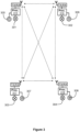
- FIG. 3 illustrates a lighting system according to an exemplifying and non-limiting embodiment.
- the lighting system comprises luminaires 301, 302, 303, and 304.
- the lighting system comprises a management system according to an exemplifying and non-limiting embodiment for controlling the luminaires 301-304.
- the luminaires 303-304 can be manually controllable with control means e.g. control buttons.
- the management system comprises light sensors 305, 306, 307, and 308 configured to produce light measurement signals indicative of light falling on the light sensors.
- the management system comprises a lighting control system that is configured to control the luminaires 301-305 in accordance with one or more control parameters.
- the management system comprises a data processing system that is configured to form one or more dependency indicators each expressing dependence of one of the light measurement signals on an operational status of one of the luminaires 301-304.
- the data processing system is configured to set the one or more control parameters based on at least the one or more dependency indicators.
- both the above-mentioned lighting control system and the data processing system are implemented with processors 315, 316, 317, and 318 installed on the luminaires 201-204.
- both the lighting control system and the data processing system have a distributed architecture.
- Each of the luminaires 301-304 comprises a transmitter TX configured to transmit a light status signal of the luminaire to the other luminaires.
- Each of the luminaires 301-304 comprises a receiver RX configured to receive the light status signals from the other luminaires.
- the processor of each luminaire is configured to deduce the operational statures of the other luminaires based on the received light status signals. Furthermore, the light measurement signal measured by the light sensor of each luminaire can be transmitted to the other luminaires.
- management systems according to different embodiments of the invention can be implemented according to many different architectures. Three exemplifying architectures are described above with reference to figures 1-3 .
- a management system according to an exemplifying and non-limiting embodiment may comprise many processor units which are separate from both luminaires and light sensors, and which are communicatively connected to the light sensors and to the luminaires.
- management systems according to different embodiments of the invention are not limited to any specific implementation architectures.
- the processing device 110 shown in figure 1 can be implemented with one or more data processors each of which can be a programmable data processor provided with an appropriate software, a dedicated hardware data processor such as for example an application specific integrated circuit "ASIC", and/or a configurable hardware data processor such as for example a field programmable gate array "FPGA".
- the processing device 110 may comprise one or more memory devices such as e.g. a random-access memory "RAM" circuit.
- each of the other processing devices and each of the controller devices shown in figures 1-3 can be implemented with one or more data processors and one or more memory devices.
- Figure 4 shows a flowchart of a method according to an exemplifying and non-limiting embodiment for controlling one or more luminaires. The method comprises the following actions:
- the one or more control parameters comprise a target illuminance level for an area illuminated by the one or more luminaires
- the method comprises setting the target illuminance level based on at least the one or more dependency indicators so that the target illuminance level is a decreasing function of each of the one or more dependency indicators.
- a method comprises forming the above-mentioned one or more dependency indicators over a sliding time-window.
- a method comprises forming the above-mentioned one or more dependency indicators over temporally successive time windows which are non-overlapping with each other.
- the method comprises forming one or more dependency indicators related to the light measurement signal produced by a first one of the light sensors more often than forming one or more dependency indicators related to the one or more light measurement signals produced by one or more second ones of the light sensors.
- the method comprises forming the one or more dependency indicators related to the one or more light measurement signals produced by the one or more second ones of the light sensors in response to a situation in which one or more changes of the one or more dependency indicators related to the light measurement signal produced by the first one of the light sensors exceed a predetermined limit.
- a method comprises maintaining season-specific rules for changing the one or more control parameters based on at least the one or more dependency indicators and selecting, in accordance with a current season, one of the season-specific rules to be used.
- the one or more dependency indicators are one or more correlations between the one or more light measurement signals and the one or more operational statuses of the one or more luminaires
- the one or more dependency indicators are formed and the one or more control parameters are set by a processing device that receives the one or more light measurement signals and information indicative of the one or more operational statuses of the one or more luminaires via one or more data transfer links and transmits the one or more control parameters via one or more data transfer links.
- the one or more luminaires are controlled in accordance with the one or more control parameters by a controller device that transmits one or more lighting control signals via one or more data transfer links to the one or more luminaires and receives the one or more control parameters via one or more data transfer links.
- the one or more dependency indicators are formed, the one or more control parameters are set, and the one or more luminaires are controlled in accordance with the one or more control parameters by one or more controllers installed on the one or more luminaires each of which transmits a light status signal of the luminaire via one or more data transfer links to the other luminaires.
- a data processor program comprises data processor executable instructions for controlling a programmable data processing system to carry out actions related to a method according to any of the above-described exemplifying embodiments.
- a data processor program comprises software modules for controlling luminaires.
- the software modules comprise data processor executable instructions for controlling a programmable data processing system to:
- the above-mentioned software modules can be e.g. subroutines or functions implemented with a programming language suitable for the programmable data processor system.
- a data processor program product comprises a data processor readable medium encoded with a data processor program according to an embodiment of invention.
- a nonvolatile data processor readable medium is encoded with a data processor program according to an embodiment of invention.
- a signal according to an exemplifying and non-limiting embodiment is encoded to carry information defining a data processor program according to an embodiment of invention.
Landscapes
- Circuit Arrangement For Electric Light Sources In General (AREA)
Claims (15)
- Verwaltungssystem zum Steuern von einer oder mehreren Leuchten (101-104, 201-204, 301-304), wobei das Verwaltungssystem Folgendes umfasst:- einen oder mehrere Lichtsensoren (105, 106, 205, 206, 305-308), die konfiguriert sind, um ein oder mehrere Lichtmesssignale zu produzieren, die auf auf den einen oder die mehreren Lichtsensoren fallendes Licht hinweisen, und- ein Beleuchtungssteuersystem (109, 211-214, 315-318), das konfiguriert ist, um die eine oder die mehreren Leuchten gemäß einem oder mehreren Steuerparametern zu steuern,dadurch gekennzeichnet, dass das Verwaltungssystem ein Datenverarbeitungssystem (110, 210, 315-318) umfasst, das konfiguriert ist, um:- einen oder mehrere Abhängigkeitsindikatoren zu bilden, die eine Abhängigkeit des einen oder der mehreren Lichtmesssignale von einem oder mehreren Betriebsstatus der einen oder der mehreren Leuchten ausdrücken, und- den einen oder die mehreren Steuerparameter basierend auf mindestens dem einen oder den mehreren Abhängigkeitsindikatoren festzulegen.
- Verwaltungssystem nach Anspruch 1, wobei das Datenverarbeitungssystem konfiguriert ist, um eine Zielbeleuchtungsstärke basierend auf mindestens dem einen oder den mehreren Abhängigkeitsindikatoren festzulegen, so dass die Zielbeleuchtungsstärke eine abnehmende Funktion jedes des einen oder der mehreren Abhängigkeitsindikatoren ist, wobei die Zielbeleuchtungsstärke zu dem einen oder den mehreren Steuerparametern des Beleuchtungssteuersystems gehört.
- Verwaltungssystem nach Anspruch 1 oder 2, wobei das Datenverarbeitungssystem konfiguriert ist, um den einen oder die mehreren Abhängigkeitsindikatoren über ein gleitendes Zeitfenster zu bilden.
- Verwaltungssystem nach Anspruch 1 oder 2, wobei das Datenverarbeitungssystem konfiguriert ist, um den einen oder die mehreren Abhängigkeitsindikatoren über zeitlich aufeinanderfolgende Zeitfenster zu bilden, die sich nicht miteinander überlappen.
- Verwaltungssystem nach einem der Ansprüche 1-4, wobei das Verwaltungssystem viele Lichtsensoren umfasst und das Datenverarbeitungssystem konfiguriert ist, um jeden des einen oder der mehreren Abhängigkeitsindikatoren in Verbindung mit dem Lichtmesssignal, das von einem ersten der Lichtsensoren produziert wird, öfter zu bilden, als jeden des einen oder der mehreren Abhängigkeitsindikatoren in Verbindung mit dem einen oder den mehreren Lichtmesssignalen zu bilden, die von einem oder mehreren zweiten der Lichtsensoren produziert werden.
- Verwaltungssystem nach Anspruch 5, wobei das Datenverarbeitungssystem konfiguriert ist, um den einen oder die mehreren Abhängigkeitsindikatoren in Verbindung mit dem einen oder den mehreren Lichtmesssignalen, die von dem einen oder den mehreren zweiten der Lichtsensoren produziert werden, als Reaktion auf eine Situation zu bilden, in welcher eine oder mehrere Änderungen des einen oder der mehreren Abhängigkeitsindikatoren in Verbindung mit dem Lichtmesssignal, das von dem ersten der Lichtsensoren produziert wird, eine vorgegebene Grenze überschreiten.
- Verwaltungssystem nach einem der Ansprüche 1-6, wobei das Datenverarbeitungssystem konfiguriert ist, um jahreszeitenspezifische Regeln zum Ändern des einen oder der mehreren Steuerparameter basierend auf mindestens dem einen oder den mehreren Abhängigkeitsindikatoren beizubehalten und gemäß einer aktuellen Jahreszeit eine der zu verwendenden jahreszeitspezifischen Regeln auszuwählen.
- Verwaltungssystem nach einem der Ansprüche 1-7, wobei der eine oder die mehreren Abhängigkeitsindikatoren eine oder mehrere Korrelationen zwischen dem einen oder den mehreren Lichtmesssignalen und dem einen oder den mehreren Betriebsstatus der einen oder der mehreren Leuchten sind und das Datenverarbeitungssystem konfiguriert ist, um jede der einen oder der mehreren Korrelationen gemäß der folgenden Gleichung zu berechnen:

- Verwaltungssystem nach einem der Ansprüche 1-8, wobei das Verwaltungssystem viele Lichtsensoren umfasst und das Datenverarbeitungssystem konfiguriert ist, um:- Differenzindikatoren zu bilden, die jeweils zwischen zwei der Lichtmesssignale liegen und eine Differenz zwischen zeitlichen Verhalten der beiden Lichtmesssignale angeben,- basierend auf den Differenzindikatoren die Lichtmesssignale in Gruppen zu klassifizieren, wo innerhalb jeder Gruppe die Lichtmesssignale einander gleichen, und- den einen oder die mehreren Abhängigkeitsindikatoren unter Verwendung nur eines Lichtmesssignals aus jeder Gruppe zu bilden.
- Verwaltungssystem nach Anspruch 9, wobei das Datenverarbeitungssystem konfiguriert ist, um jeden der Differenzindikatoren gemäß der folgenden Gleichung zu berechnen:

- Verwaltungssystem nach einem der Ansprüche 1-10, wobei das Datenverarbeitungssystem eine Verarbeitungsvorrichtung (110, 210) ist, die Folgendes umfasst:- einen Empfänger (RX), der konfiguriert ist, um das eine oder die mehreren Lichtmesssignale von dem einen oder den mehreren Lichtsensoren und ein oder mehrere Beleuchtungssteuersignale von dem Beleuchtungssteuersystem zu empfangen, wobei das eine oder die mehreren Beleuchtungssteuersignale den einen oder die mehreren Betriebsstatus der einen oder der mehreren Leuchten definieren, und- einen Sender (TX), der konfiguriert ist, um den einen oder die mehreren Steuerparameter zu dem Beleuchtungssteuersystem zu senden.
- Verwaltungssystem nach einem der Ansprüche 1-11, wobei das Beleuchtungssteuersystem eine Steuervorrichtung (109) ist, die Folgendes umfasst:- einen Sender (TX), der konfiguriert ist, um ein oder mehrere Beleuchtungssteuersignale zu dem Datenverarbeitungssystem und zu der einen oder den mehreren Leuchten zu senden, wobei das eine oder die mehreren Beleuchtungssteuersignale den einen oder die mehreren Betriebsstatus der einen oder der mehreren Leuchten definieren, und- einen Empfänger (RX), der konfiguriert ist, um den einen oder die mehreren Steuerparameter von dem Datenverarbeitungssystem zu empfangen.
- Beleuchtungssystem umfassend:- eine oder mehrere Leuchten (101-104, 201-204, 301-304) und- ein Verwaltungssystem nach einem der Ansprüche 1-12, das konfiguriert ist, um die eine oder die mehreren Leuchten zu steuern.
- Verfahren zum Steuern von einer oder mehreren Leuchten, wobei das Verfahren Folgendes umfasst:- Produzieren (401) von einem oder mehreren Lichtmesssignalen, die auf auf einen oder mehrere Lichtsensoren fallendes Licht hinweisen, und- Steuern (402) der einen oder der mehreren Leuchten gemäß einem oder mehreren Steuerparametern,dadurch gekennzeichnet, dass das Verfahren Folgendes umfasst:- Bilden (403) eines oder mehrerer Abhängigkeitsindikatoren, die eine Abhängigkeit des einen oder der mehreren Lichtmesssignale von einem oder mehreren Betriebsstatus der einen oder der mehreren Leuchten ausdrücken, und- Festlegen (404) des einen oder der mehreren Steuerparameter basierend auf mindestens dem einen oder den mehreren Abhängigkeitsindikatoren.
- Datenprozessorprogramm zum Steuern von einer oder mehreren Leuchten, wobei das Datenverarbeitungsprogramm von einem Datenprozessor ausführbare Anweisungen zum Steuern eines programmierbaren Datenverarbeitungssystems umfasst, um:- ein oder mehrere Lichtmesssignale, die auf auf einen oder mehrere Lichtsensoren fallendes Licht hinweisen, und Informationen, die einen Betriebsstatus jeder der einen oder mehreren Leuchten angeben, zu empfangen,dadurch gekennzeichnet, dass das Datenverarbeitungsprogramm von einem Datenprozessor ausführbare Anweisungen zum Steuern des programmierbaren Datenverarbeitungssystems umfasst, um:- einen oder mehrere Abhängigkeitsindikatoren zu bilden, die eine Abhängigkeit des einen oder der mehreren Lichtmesssignale von dem einen oder den mehreren Betriebsstatus der einen oder der mehreren Leuchten ausdrücken, und- basierend auf mindestens dem einen oder den mehreren Abhängigkeitsindikatoren einen oder mehrere Steuerparameter eines Beleuchtungssteuersystems festzulegen, das konfiguriert ist, um die eine oder die mehreren Leuchten gemäß dem einen oder den mehreren Steuerparametern zu steuern.
Applications Claiming Priority (1)
| Application Number | Priority Date | Filing Date | Title |
|---|---|---|---|
| FI20216227A FI130023B (en) | 2021-11-30 | 2021-11-30 | Control system and method for controlling lighting fixtures |
Publications (2)
| Publication Number | Publication Date |
|---|---|
| EP4188039A1 EP4188039A1 (de) | 2023-05-31 |
| EP4188039B1 true EP4188039B1 (de) | 2025-01-29 |
Family
ID=84272931
Family Applications (1)
| Application Number | Title | Priority Date | Filing Date |
|---|---|---|---|
| EP22209513.5A Active EP4188039B1 (de) | 2021-11-30 | 2022-11-25 | Verwaltungssystem und verfahren zur steuerung von leuchten |
Country Status (2)
| Country | Link |
|---|---|
| EP (1) | EP4188039B1 (de) |
| FI (1) | FI130023B (de) |
Family Cites Families (6)
| Publication number | Priority date | Publication date | Assignee | Title |
|---|---|---|---|---|
| KR101568486B1 (ko) * | 2013-12-06 | 2015-11-11 | 대우조선해양 주식회사 | 잠수함의 장비 상태 표시등 제어시스템 |
| EP3155877B1 (de) * | 2014-06-10 | 2019-01-30 | Philips Lighting Holding B.V. | Anfragereaktion für vernetzte verteilte beleuchtungssysteme |
| EP3512672B1 (de) * | 2016-09-14 | 2022-06-15 | Koninklijke Philips N.V. | Pflegesystem mit adaptiver beleuchtung und betriebsverfahren |
| EP3799533B1 (de) * | 2019-09-27 | 2024-07-17 | Helvar Oy Ab | Selbstadaptive beleuchtungssteuerung |
| EP3846591B1 (de) * | 2019-12-30 | 2024-10-02 | Helvar Oy Ab | Beleuchtungssteuerung |
| EP3908083B1 (de) * | 2020-05-05 | 2024-03-06 | Helvar Oy Ab | Verwaltungssystem und verfahren zur steuerung von leuchten |
-
2021
- 2021-11-30 FI FI20216227A patent/FI130023B/en active
-
2022
- 2022-11-25 EP EP22209513.5A patent/EP4188039B1/de active Active
Also Published As
| Publication number | Publication date |
|---|---|
| FI130023B (en) | 2022-12-30 |
| FI20216227A1 (en) | 2022-12-30 |
| EP4188039A1 (de) | 2023-05-31 |
Similar Documents
| Publication | Publication Date | Title |
|---|---|---|
| US9148935B2 (en) | Dual-technology occupancy detection | |
| US8364325B2 (en) | Intelligence in distributed lighting control devices | |
| US9679473B2 (en) | Illumination apparatus methods and systems | |
| EP3089559B1 (de) | Dynamische weglichthelligkeit auf basis von grösse und entfernung von bewegung/gegenstand, der sich der vorrichtung nähert | |
| CN115211236A (zh) | 多个建筑技术传感器模块的格栅以及包括此类格栅的系统 | |
| EP4188039A1 (de) | Verwaltungssystem und verfahren zur steuerung von leuchten | |
| EP3529788B1 (de) | System und verfahren zur anwesenheitserkennung | |
| EP3908083B1 (de) | Verwaltungssystem und verfahren zur steuerung von leuchten | |
| EP3300459B1 (de) | Verfahren und anordnung zur beleuchtungssteuerung auf der basis von benutzerverfolgung | |
| US10372097B2 (en) | Adaptive adjustment of motion sensitivity of a motion sensor | |
| EP3972391B1 (de) | Modellierung von umgebungseigenschaften basierend auf sensordaten, die in einem beleuchtungssystem erhältlich sind | |
| EP3792826A1 (de) | System und verfahren zur detektion von nir-bewegung | |
| US10783767B2 (en) | Device and method for controlling bluetooth enabled occupancy sensors | |
| EP4271139A1 (de) | Lichtsteuerung | |
| JP6288843B2 (ja) | 制御システム | |
| EP4236629B1 (de) | Beleuchtungssteuerung | |
| JP2019175780A (ja) | 照明制御システム、照明制御装置及び照明制御方法 | |
| EP4203624A1 (de) | Beleuchtungssteuerung | |
| EP4376555A1 (de) | Beleuchtungssteuerung | |
| EP4432783A1 (de) | Verfahren zur steuerung eines betriebszustandes mindestens eines zusatzgerätes im beleuchtungssystem, leuchte und beleuchtungssystem | |
| EP4260662B1 (de) | Intelligentes notbeleuchtungssystem und leuchte | |
| CN117896865B (zh) | 一种人体感应式智能触控led小夜灯控制方法 | |
| FI129261B (en) | Lighting control | |
| CN120321853A (zh) | 基于传感器的智能家居光照强度监控自动调节方法 | |
| JP7589596B2 (ja) | 照明制御システム |
Legal Events
| Date | Code | Title | Description |
|---|---|---|---|
| PUAI | Public reference made under article 153(3) epc to a published international application that has entered the european phase |
Free format text: ORIGINAL CODE: 0009012 |
|
| STAA | Information on the status of an ep patent application or granted ep patent |
Free format text: STATUS: THE APPLICATION HAS BEEN PUBLISHED |
|
| AK | Designated contracting states |
Kind code of ref document: A1 Designated state(s): AL AT BE BG CH CY CZ DE DK EE ES FI FR GB GR HR HU IE IS IT LI LT LU LV MC ME MK MT NL NO PL PT RO RS SE SI SK SM TR |
|
| STAA | Information on the status of an ep patent application or granted ep patent |
Free format text: STATUS: REQUEST FOR EXAMINATION WAS MADE |
|
| 17P | Request for examination filed |
Effective date: 20231120 |
|
| RBV | Designated contracting states (corrected) |
Designated state(s): AL AT BE BG CH CY CZ DE DK EE ES FI FR GB GR HR HU IE IS IT LI LT LU LV MC ME MK MT NL NO PL PT RO RS SE SI SK SM TR |
|
| GRAP | Despatch of communication of intention to grant a patent |
Free format text: ORIGINAL CODE: EPIDOSNIGR1 |
|
| STAA | Information on the status of an ep patent application or granted ep patent |
Free format text: STATUS: GRANT OF PATENT IS INTENDED |
|
| INTG | Intention to grant announced |
Effective date: 20241010 |
|
| GRAS | Grant fee paid |
Free format text: ORIGINAL CODE: EPIDOSNIGR3 |
|
| GRAA | (expected) grant |
Free format text: ORIGINAL CODE: 0009210 |
|
| STAA | Information on the status of an ep patent application or granted ep patent |
Free format text: STATUS: THE PATENT HAS BEEN GRANTED |
|
| AK | Designated contracting states |
Kind code of ref document: B1 Designated state(s): AL AT BE BG CH CY CZ DE DK EE ES FI FR GB GR HR HU IE IS IT LI LT LU LV MC ME MK MT NL NO PL PT RO RS SE SI SK SM TR |
|
| REG | Reference to a national code |
Ref country code: GB Ref legal event code: FG4D |
|
| REG | Reference to a national code |
Ref country code: CH Ref legal event code: EP |
|
| REG | Reference to a national code |
Ref country code: DE Ref legal event code: R096 Ref document number: 602022010073 Country of ref document: DE |
|
| REG | Reference to a national code |
Ref country code: IE Ref legal event code: FG4D |
|
| REG | Reference to a national code |
Ref country code: NL Ref legal event code: MP Effective date: 20250129 |
|
| PG25 | Lapsed in a contracting state [announced via postgrant information from national office to epo] |
Ref country code: NL Free format text: LAPSE BECAUSE OF FAILURE TO SUBMIT A TRANSLATION OF THE DESCRIPTION OR TO PAY THE FEE WITHIN THE PRESCRIBED TIME-LIMIT Effective date: 20250129 |
|
| PG25 | Lapsed in a contracting state [announced via postgrant information from national office to epo] |
Ref country code: RS Free format text: LAPSE BECAUSE OF FAILURE TO SUBMIT A TRANSLATION OF THE DESCRIPTION OR TO PAY THE FEE WITHIN THE PRESCRIBED TIME-LIMIT Effective date: 20250429 |
|
| PG25 | Lapsed in a contracting state [announced via postgrant information from national office to epo] |
Ref country code: FI Free format text: LAPSE BECAUSE OF FAILURE TO SUBMIT A TRANSLATION OF THE DESCRIPTION OR TO PAY THE FEE WITHIN THE PRESCRIBED TIME-LIMIT Effective date: 20250129 |
|
| PG25 | Lapsed in a contracting state [announced via postgrant information from national office to epo] |
Ref country code: PL Free format text: LAPSE BECAUSE OF FAILURE TO SUBMIT A TRANSLATION OF THE DESCRIPTION OR TO PAY THE FEE WITHIN THE PRESCRIBED TIME-LIMIT Effective date: 20250129 |
|
| PG25 | Lapsed in a contracting state [announced via postgrant information from national office to epo] |
Ref country code: ES Free format text: LAPSE BECAUSE OF FAILURE TO SUBMIT A TRANSLATION OF THE DESCRIPTION OR TO PAY THE FEE WITHIN THE PRESCRIBED TIME-LIMIT Effective date: 20250129 |
|
| REG | Reference to a national code |
Ref country code: LT Ref legal event code: MG9D |
|
| PG25 | Lapsed in a contracting state [announced via postgrant information from national office to epo] |
Ref country code: NO Free format text: LAPSE BECAUSE OF FAILURE TO SUBMIT A TRANSLATION OF THE DESCRIPTION OR TO PAY THE FEE WITHIN THE PRESCRIBED TIME-LIMIT Effective date: 20250429 Ref country code: IS Free format text: LAPSE BECAUSE OF FAILURE TO SUBMIT A TRANSLATION OF THE DESCRIPTION OR TO PAY THE FEE WITHIN THE PRESCRIBED TIME-LIMIT Effective date: 20250529 |
|
| REG | Reference to a national code |
Ref country code: AT Ref legal event code: MK05 Ref document number: 1764685 Country of ref document: AT Kind code of ref document: T Effective date: 20250129 |
|
| PG25 | Lapsed in a contracting state [announced via postgrant information from national office to epo] |
Ref country code: HR Free format text: LAPSE BECAUSE OF FAILURE TO SUBMIT A TRANSLATION OF THE DESCRIPTION OR TO PAY THE FEE WITHIN THE PRESCRIBED TIME-LIMIT Effective date: 20250129 |
|
| PG25 | Lapsed in a contracting state [announced via postgrant information from national office to epo] |
Ref country code: LV Free format text: LAPSE BECAUSE OF FAILURE TO SUBMIT A TRANSLATION OF THE DESCRIPTION OR TO PAY THE FEE WITHIN THE PRESCRIBED TIME-LIMIT Effective date: 20250129 Ref country code: PT Free format text: LAPSE BECAUSE OF FAILURE TO SUBMIT A TRANSLATION OF THE DESCRIPTION OR TO PAY THE FEE WITHIN THE PRESCRIBED TIME-LIMIT Effective date: 20250529 |
|
| PG25 | Lapsed in a contracting state [announced via postgrant information from national office to epo] |
Ref country code: GR Free format text: LAPSE BECAUSE OF FAILURE TO SUBMIT A TRANSLATION OF THE DESCRIPTION OR TO PAY THE FEE WITHIN THE PRESCRIBED TIME-LIMIT Effective date: 20250430 Ref country code: BG Free format text: LAPSE BECAUSE OF FAILURE TO SUBMIT A TRANSLATION OF THE DESCRIPTION OR TO PAY THE FEE WITHIN THE PRESCRIBED TIME-LIMIT Effective date: 20250129 |
|
| PG25 | Lapsed in a contracting state [announced via postgrant information from national office to epo] |
Ref country code: AT Free format text: LAPSE BECAUSE OF FAILURE TO SUBMIT A TRANSLATION OF THE DESCRIPTION OR TO PAY THE FEE WITHIN THE PRESCRIBED TIME-LIMIT Effective date: 20250129 |
|
| PG25 | Lapsed in a contracting state [announced via postgrant information from national office to epo] |
Ref country code: SE Free format text: LAPSE BECAUSE OF FAILURE TO SUBMIT A TRANSLATION OF THE DESCRIPTION OR TO PAY THE FEE WITHIN THE PRESCRIBED TIME-LIMIT Effective date: 20250129 |
|
| PG25 | Lapsed in a contracting state [announced via postgrant information from national office to epo] |
Ref country code: SM Free format text: LAPSE BECAUSE OF FAILURE TO SUBMIT A TRANSLATION OF THE DESCRIPTION OR TO PAY THE FEE WITHIN THE PRESCRIBED TIME-LIMIT Effective date: 20250129 |
|
| PG25 | Lapsed in a contracting state [announced via postgrant information from national office to epo] |
Ref country code: DK Free format text: LAPSE BECAUSE OF FAILURE TO SUBMIT A TRANSLATION OF THE DESCRIPTION OR TO PAY THE FEE WITHIN THE PRESCRIBED TIME-LIMIT Effective date: 20250129 |
|
| PG25 | Lapsed in a contracting state [announced via postgrant information from national office to epo] |
Ref country code: IT Free format text: LAPSE BECAUSE OF FAILURE TO SUBMIT A TRANSLATION OF THE DESCRIPTION OR TO PAY THE FEE WITHIN THE PRESCRIBED TIME-LIMIT Effective date: 20250129 |
|
| PG25 | Lapsed in a contracting state [announced via postgrant information from national office to epo] |
Ref country code: EE Free format text: LAPSE BECAUSE OF FAILURE TO SUBMIT A TRANSLATION OF THE DESCRIPTION OR TO PAY THE FEE WITHIN THE PRESCRIBED TIME-LIMIT Effective date: 20250129 Ref country code: CZ Free format text: LAPSE BECAUSE OF FAILURE TO SUBMIT A TRANSLATION OF THE DESCRIPTION OR TO PAY THE FEE WITHIN THE PRESCRIBED TIME-LIMIT Effective date: 20250129 |
|
| PG25 | Lapsed in a contracting state [announced via postgrant information from national office to epo] |
Ref country code: RO Free format text: LAPSE BECAUSE OF FAILURE TO SUBMIT A TRANSLATION OF THE DESCRIPTION OR TO PAY THE FEE WITHIN THE PRESCRIBED TIME-LIMIT Effective date: 20250129 |
|
| PG25 | Lapsed in a contracting state [announced via postgrant information from national office to epo] |
Ref country code: SK Free format text: LAPSE BECAUSE OF FAILURE TO SUBMIT A TRANSLATION OF THE DESCRIPTION OR TO PAY THE FEE WITHIN THE PRESCRIBED TIME-LIMIT Effective date: 20250129 |
|
| REG | Reference to a national code |
Ref country code: DE Ref legal event code: R097 Ref document number: 602022010073 Country of ref document: DE |
|
| PLBE | No opposition filed within time limit |
Free format text: ORIGINAL CODE: 0009261 |
|
| STAA | Information on the status of an ep patent application or granted ep patent |
Free format text: STATUS: NO OPPOSITION FILED WITHIN TIME LIMIT |
|
| 26N | No opposition filed |
Effective date: 20251030 |
|
| PGFP | Annual fee paid to national office [announced via postgrant information from national office to epo] |
Ref country code: DE Payment date: 20251128 Year of fee payment: 4 |