EP4187940B1 - Informationsübertragungsverfahren, -vorrichtung und -system - Google Patents
Informationsübertragungsverfahren, -vorrichtung und -system Download PDFInfo
- Publication number
- EP4187940B1 EP4187940B1 EP21853160.6A EP21853160A EP4187940B1 EP 4187940 B1 EP4187940 B1 EP 4187940B1 EP 21853160 A EP21853160 A EP 21853160A EP 4187940 B1 EP4187940 B1 EP 4187940B1
- Authority
- EP
- European Patent Office
- Prior art keywords
- mapping
- terminal device
- rnti
- period
- network device
- Prior art date
- Legal status (The legal status is an assumption and is not a legal conclusion. Google has not performed a legal analysis and makes no representation as to the accuracy of the status listed.)
- Active
Links
Images


Classifications
-
- H—ELECTRICITY
- H04—ELECTRIC COMMUNICATION TECHNIQUE
- H04B—TRANSMISSION
- H04B7/00—Radio transmission systems, i.e. using radiation field
- H04B7/02—Diversity systems; Multi-antenna system, i.e. transmission or reception using multiple antennas
- H04B7/04—Diversity systems; Multi-antenna system, i.e. transmission or reception using multiple antennas using two or more spaced independent antennas
- H04B7/06—Diversity systems; Multi-antenna system, i.e. transmission or reception using multiple antennas using two or more spaced independent antennas at the transmitting station
- H04B7/0686—Hybrid systems, i.e. switching and simultaneous transmission
- H04B7/0695—Hybrid systems, i.e. switching and simultaneous transmission using beam selection
-
- H—ELECTRICITY
- H04—ELECTRIC COMMUNICATION TECHNIQUE
- H04W—WIRELESS COMMUNICATION NETWORKS
- H04W52/00—Power management, e.g. Transmission Power Control [TPC] or power classes
- H04W52/02—Power saving arrangements
- H04W52/0209—Power saving arrangements in terminal devices
- H04W52/0212—Power saving arrangements in terminal devices managed by the network, e.g. network or access point is leader and terminal is follower
- H04W52/0219—Power saving arrangements in terminal devices managed by the network, e.g. network or access point is leader and terminal is follower where the power saving management affects multiple terminals
-
- H—ELECTRICITY
- H04—ELECTRIC COMMUNICATION TECHNIQUE
- H04L—TRANSMISSION OF DIGITAL INFORMATION, e.g. TELEGRAPHIC COMMUNICATION
- H04L5/00—Arrangements affording multiple use of the transmission path
- H04L5/003—Arrangements for allocating sub-channels of the transmission path
- H04L5/0053—Allocation of signalling, i.e. of overhead other than pilot signals
-
- H—ELECTRICITY
- H04—ELECTRIC COMMUNICATION TECHNIQUE
- H04W—WIRELESS COMMUNICATION NETWORKS
- H04W4/00—Services specially adapted for wireless communication networks; Facilities therefor
- H04W4/06—Selective distribution of broadcast services, e.g. multimedia broadcast multicast service [MBMS]; Services to user groups; One-way selective calling services
-
- H—ELECTRICITY
- H04—ELECTRIC COMMUNICATION TECHNIQUE
- H04W—WIRELESS COMMUNICATION NETWORKS
- H04W72/00—Local resource management
- H04W72/04—Wireless resource allocation
- H04W72/044—Wireless resource allocation based on the type of the allocated resource
-
- H—ELECTRICITY
- H04—ELECTRIC COMMUNICATION TECHNIQUE
- H04W—WIRELESS COMMUNICATION NETWORKS
- H04W72/00—Local resource management
- H04W72/04—Wireless resource allocation
- H04W72/044—Wireless resource allocation based on the type of the allocated resource
- H04W72/0446—Resources in time domain, e.g. slots or frames
-
- H—ELECTRICITY
- H04—ELECTRIC COMMUNICATION TECHNIQUE
- H04W—WIRELESS COMMUNICATION NETWORKS
- H04W72/00—Local resource management
- H04W72/12—Wireless traffic scheduling
- H04W72/121—Wireless traffic scheduling for groups of terminals or users
-
- H—ELECTRICITY
- H04—ELECTRIC COMMUNICATION TECHNIQUE
- H04W—WIRELESS COMMUNICATION NETWORKS
- H04W76/00—Connection management
- H04W76/20—Manipulation of established connections
- H04W76/28—Discontinuous transmission [DTX]; Discontinuous reception [DRX]
-
- H—ELECTRICITY
- H04—ELECTRIC COMMUNICATION TECHNIQUE
- H04W—WIRELESS COMMUNICATION NETWORKS
- H04W72/00—Local resource management
- H04W72/20—Control channels or signalling for resource management
- H04W72/23—Control channels or signalling for resource management in the downlink direction of a wireless link, i.e. towards a terminal
- H04W72/232—Control channels or signalling for resource management in the downlink direction of a wireless link, i.e. towards a terminal the control data signalling from the physical layer, e.g. DCI signalling
-
- H—ELECTRICITY
- H04—ELECTRIC COMMUNICATION TECHNIQUE
- H04W—WIRELESS COMMUNICATION NETWORKS
- H04W72/00—Local resource management
- H04W72/30—Resource management for broadcast services
-
- Y—GENERAL TAGGING OF NEW TECHNOLOGICAL DEVELOPMENTS; GENERAL TAGGING OF CROSS-SECTIONAL TECHNOLOGIES SPANNING OVER SEVERAL SECTIONS OF THE IPC; TECHNICAL SUBJECTS COVERED BY FORMER USPC CROSS-REFERENCE ART COLLECTIONS [XRACs] AND DIGESTS
- Y02—TECHNOLOGIES OR APPLICATIONS FOR MITIGATION OR ADAPTATION AGAINST CLIMATE CHANGE
- Y02D—CLIMATE CHANGE MITIGATION TECHNOLOGIES IN INFORMATION AND COMMUNICATION TECHNOLOGIES [ICT], I.E. INFORMATION AND COMMUNICATION TECHNOLOGIES AIMING AT THE REDUCTION OF THEIR OWN ENERGY USE
- Y02D30/00—Reducing energy consumption in communication networks
- Y02D30/70—Reducing energy consumption in communication networks in wireless communication networks
Definitions
- the present invention relates to the field of wireless communication, and in particular, to information transmission in the field of wireless communication.
- a multimedia broadcast multicast service (Multimedia Broadcast Multicast Service, MBMS) or a multicast broadcast service (multicast broadcast service, MBS) is a service oriented to a plurality of terminal devices, for example, live streaming or scheduled program playing.
- a multicast transmission technology is a technology in which a base station simultaneously sends MBS service information to a plurality of terminal devices.
- a base station sends a broadcast beam to a terminal device in a beam sweeping manner, the terminal device selects, in a beam training manner, a beam with best signal quality for the terminal device, and a network device and the terminal device transmit information by using the selected beam, to achieve a best transmission effect.
- a network device configures monitoring occasions of a plurality of terminal devices, and the plurality of terminal devices perform monitoring on the monitoring occasions, and decode corresponding downlink control information (Downlink Control Information, DCI) carried on a physical downlink control channel (Physical Downlink Control Channel, PDCCH), to obtain broadcast information.
- DCI Downlink Control Information
- PDCCH Physical Downlink Control Channel
- monitoring is performed on a beam.
- the network device may not transmit information by using the beam, or a beam swept in this case is not a beam selected by the terminal device through beam training, and the terminal device cannot obtain information sent by the network device. All these reduce monitoring efficiency of the terminal device and cause power consumption of the terminal device, resulting in a waste of resources.
- US 2018/049060 A1 relates to a base station that provides multicast service by SC-PTM (Single Cell Point to Multipoint) transmission.
- the base station includes a controller configured to perform processing of transmitting SC-PTM configuration information related to a configuration of the SC-PTM transmission via a GCCH (SC-PTM control channel) which is a logical channel different from a MCCH.
- SC-PTM control channel SC-PTM control channel
- the GCCH is mapped on the DL-SCH.
- This application provides an information transmission method and an apparatus, to improve information transmission efficiency in a communication system, and avoid as much as possible problems of power consumption and resource waste caused when a terminal device blindly listens to information on all monitoring occasions.
- the invention is defined by the attached set of claims. Further details of the disclosed methods, devices and system are provided in the following, which are helpful for understanding the claimed invention.
- this application provides a communication method.
- the method may be performed by a network device or a chip in the network device.
- the following provides descriptions by using an example in which the method is performed by the network device.
- the network device determines a mapping period of a first radio network temporary identifier RNTI, and the network device sends first information to a terminal device on a first monitoring occasion corresponding to a first beam by using the first beam.
- the first information is scrambled by using the first RNTI.
- the first beam and the first monitoring occasion that is in a first mapping period of the first RNTI meet a first mapping relationship, and the first mapping period is any mapping period of the first RNTI.
- the first monitoring occasion is a set of monitoring occasions that correspond to the first beam and that are located in a first mapping window.
- the network device may obtain, by configuring the mapping period of the first RNTI, the first mapping period that appears consecutively in time domain.
- the first beam and the first monitoring occasion meet the first mapping relationship in the first mapping period.
- the network device configures a transmission resource of the first beam on the first monitoring occasion based on the first mapping relationship. This avoids a case in which the network device configures the monitoring occasion but does not configure the transmission resource of the beam, thereby improving a success rate of information transmission and air interface resource utilization, and avoiding a waste of resources.
- the plurality of monitoring occasions there are a plurality of monitoring occasions corresponding to a plurality of beams in the first mapping period.
- the plurality of monitoring occasions belong to monitoring occasions of the first RNTI, the plurality of monitoring occasions are in one or more periods of a search space, and the plurality of beams are beams sent by the network device in a cell to which the terminal device belongs.
- the monitoring occasions of the first RNTI are a set of monitoring occasions of downlink control information scrambled by using the first RNTI.
- the network device when the network device sends a plurality of beams in the cell to which the terminal device belongs, there are a plurality of monitoring occasions corresponding to the plurality of beams in the first mapping period.
- the plurality of beams and the plurality of monitoring occasions all meet the first mapping relationship in the first mapping period. Because one terminal device corresponds to one beam, in this case, a success rate of transmitting information by the network device to a plurality of terminal devices can be improved in the first mapping period, thereby avoiding invalid monitoring caused by performing resource transmission by the network device by using a beam that is not corresponding to the terminal device at a monitoring moment of the terminal device.
- the method further includes: The network device sends at least one piece of configuration information to the terminal device, where the at least one piece of configuration information indicates a first offset and/or a mapping period of the first RNTI.
- the plurality of monitoring occasions are located in the first mapping window.
- the first mapping window is determined based on the mapping period of the first RNTI and the first offset, and is duration within the first mapping period, and the plurality of monitoring occasions include the first monitoring occasion.
- a time domain start location of the first mapping window is determined based on the mapping period of the first RNTI and the first offset.
- the network device may determine the time domain start location of the first mapping window according to the rule. Based on the mapping period of the first RNTI and the first offset, or duration of the first mapping period and duration of the first offset, the network device can determine a location and duration of the first mapping window.
- a plurality of monitoring occasions correspond to a plurality of beams.
- the plurality of beams in ascending order of index values correspond to the plurality of monitoring occasions arranged in time-domain order.
- each monitoring occasion in the first mapping window corresponds to one beam
- the network device sequentially and cyclically sends a plurality of beams in ascending order of beam index values.
- the terminal device can also determine, based on a beam sending order, the first monitoring occasion on which the network device sends the first beam.
- the first beam and the first monitoring occasion meet a predefined rule
- the first offset is an offset of the search space.
- the at least one piece of configuration information further indicates a period of the search space.
- the first offset indicates an offset between a time domain start location of each period of the search space and a time domain start location of the search space in each period.
- the first offset indicates an offset between a time domain start location of the first mapping period and a time domain start location of the first mapping window, and also indicates an offset between a time domain start location of each period of the search space and a time domain start location of the search space in each period.
- the network device can configure the search space of the first RNTI more simply and effectively, and has better compatibility with the conventional technology. Further optionally, the network device may configure the time domain start location of the first mapping window to coincide with a time domain start location of at least one search space, the network device may configure the mapping period of the first RNTI to be an integer multiple of the period of the search space, or the network device may configure the period of the search space to be an integer multiple of the mapping period of the first RNTI.
- the first offset is a dedicated offset configured by the network device for the first mapping window, and the at least one piece of configuration information further indicates the period of the search space and a second offset of the search space.
- the second offset indicates an offset between a time domain start location of each period of the search space and a time domain start location of the search space in each period.
- the network device configures the dedicated offset for the first mapping window without being affected by the second offset of the search space.
- the network device may more flexibly configure the time domain start location of the search space and the time domain start location of the first mapping window.
- the search space is a common search space, or the search space is a dedicated search space configured by the network device for the first RNTI, or an MBS search space configured by the network device for RNTIs that scramble DCI of all MBS services.
- the first information includes control information
- the control information is used to schedule a multicast service for a group of terminal devices, and the group of terminal devices include the terminal device; or the control information is used to schedule a dedicated system information block.
- the method further includes: The network device sends DRX configuration information to the terminal device, where the DRX configuration information is used to configure DRX, and includes an active period and an inactive period in a DRX cycle.
- that the network device sends first information to a terminal device on a first monitoring occasion corresponding to a first beam by using the first beam includes: The network device sends the first information to the terminal device on a first monitoring sub-occasion of the first monitoring occasion by using the first beam, where the first monitoring sub-occasion is one or more monitoring occasions that are in an active period of at least one DRX cycle in the first monitoring occasion.
- the network device does not send the first information to the terminal device by using the first beam on a second monitoring sub-occasion of the first monitoring occasion corresponding to the first beam.
- the second monitoring sub-occasion is one or more monitoring occasions that are in an inactive period of at least one DRX cycle in the first monitoring occasion.
- the time domain start location of the first mapping window coincides with a time domain start location of an active period in at least one DRX cycle.
- this application provides a communication method.
- the method may be performed by a terminal device or a chip in the terminal device.
- the following provides descriptions by using an example in which the method is performed by the terminal device.
- the terminal device determines a mapping period of a first radio network temporary identifier RNTI, and the terminal device receives, on a first monitoring occasion corresponding to a first beam by using the first beam, first information sent by a network device.
- the first information is scrambled by using the first RNTI.
- the first beam and the first monitoring occasion that is in a first mapping period of the first RNTI meet a first mapping relationship
- the first mapping period is any mapping period of the first RNTI
- the first monitoring occasion is a set of monitoring occasions that correspond to the first beam and that are in the first mapping window.
- the first beam and the first monitoring occasion meet the first mapping relationship in the first mapping period.
- the terminal device listens to the first information on the first monitoring occasion based on the first mapping relationship by using the first beam, thereby improving monitoring efficiency, and avoiding invalid monitoring caused when the terminal device performs monitoring and there is no transmission resource of a beam in this case, or a beam for sending information in this case is not a beam corresponding to the terminal device.
- the plurality of monitoring occasions there are a plurality of monitoring occasions corresponding to a plurality of beams in the first mapping period.
- the plurality of monitoring occasions belong to monitoring occasions of the first RNTI, the plurality of monitoring occasions are in one or more periods of a search space, the plurality of beams are beams sent by the network device in a cell to which the terminal device belongs, and the monitoring occasions of the first RNTI are a set of monitoring occasions of downlink control information scrambled by using the first RNTI.
- the network device when the network device sends a plurality of beams in the cell to which the terminal device belongs, there are a plurality of monitoring occasions corresponding to the plurality of beams in the first mapping window.
- the plurality of beams and the plurality of monitoring occasions all meet the first mapping relationship in the first mapping window. Because one terminal device corresponds to one beam, monitoring efficiency of a plurality of terminal devices can be improved in the first mapping window.
- the method further includes: The terminal device receives at least one piece of configuration information from the network device, where the at least one piece of configuration information indicates the first offset and/or the mapping period of the first RNTI.
- the plurality of monitoring occasions are located in the first mapping window.
- the first mapping window is determined based on the mapping period of the first RNTI and the first offset, and is duration within the first mapping period, and the plurality of monitoring occasions include the first monitoring occasion.
- a time domain start location of the first mapping window is determined based on the mapping period of the first RNTI and the first offset.
- the terminal device may determine the time domain start location of the first mapping window according to the rule.
- the terminal device may determine the duration of the first mapping window based on the mapping period of the first RNTI or the duration of the first mapping period.
- a plurality of monitoring occasions correspond to a plurality of beams.
- the plurality of beams in ascending order of index values correspond to the plurality of monitoring occasions arranged in time-domain order.
- each monitoring occasion in the first mapping window corresponds to one beam
- the network device sequentially and cyclically sends a plurality of beams in ascending order of beam index values.
- the terminal device can also determine, based on a beam sending order, the first monitoring occasion on which the network device sends the first beam.
- the first beam and the first monitoring occasion meet a predefined rule
- the first offset is an offset of the search space.
- the at least one piece of configuration information further indicates a period of the search space.
- the first offset indicates an offset between a time domain start location of each period of the search space and a time domain start location of the search space in each period.
- the first offset indicates an offset between a time domain start location of the first mapping period and a time domain start location of the first mapping window, and also indicates an offset between a time domain start location of each period of the search space and a time domain start location of the search space in each period, which has better compatibility with the conventional technology.
- the time domain start location of the first mapping window may coincide with a time domain start location of at least one search space
- the mapping period of the first RNTI may be an integer multiple of the period of the search space
- the period of the search space may be an integer multiple of the mapping period of the first RNTI.
- the first offset is a dedicated offset configured by the network device for the first mapping window, and the at least one piece of configuration information further indicates the period of the search space and a second offset of the search space.
- the second offset indicates an offset between a time domain start location of each period of the search space and a time domain start location of the search space in each period.
- the network device configures a dedicated offset for the first mapping window, and the first offset and the second offset are independent of each other.
- the terminal device determines the time domain start location of the first mapping window based on the first offset and the mapping period of the first RNTI, and determines the time domain start location of the search space in each period of the search space based on the second offset and the period of the search space.
- the time domain start location of the first mapping window and the time domain start location of the search space are more flexible.
- the search space is a common search space, or the search space is a dedicated search space configured by the network device for the first RNTI, or an MBS search space configured by the network device for RNTIs that scramble DCI of all MBS services.
- the first information includes control information
- the control information is used to schedule a multicast service for a group of terminal devices
- the group of terminal devices include the terminal device
- the control information is used to schedule a dedicated system information block.
- the method further includes: The terminal device receives DRX configuration information sent by the network device, where the DRX configuration information is used to configure an active period in a DRX cycle.
- first information sent by a network device includes: The terminal device receives, on a first monitoring sub-occasion of the first monitoring occasion by using the first beam, the first information sent by the network device, where the first monitoring sub-occasion is one or more monitoring occasions that are in an active period of at least one DRX cycle in the first monitoring occasion.
- this application provides a communication method.
- the method may be performed by a network device or a chip in the network device.
- the following provides descriptions by using an example in which the method is performed by the network device.
- the network device sends DRX configuration information to a terminal device, and the network device sends first information to the terminal device on a first monitoring occasion corresponding to a first beam by using the first beam.
- the first information is scrambled by using a first RNTI.
- the first beam and the first monitoring occasion in at least one DRX cycle meet a first mapping relationship.
- the first monitoring occasion is a set of monitoring occasions that correspond to the first beam and that are in at least one DRX active period.
- the network device may obtain, by configuring DRX, DRX cycles that consecutively occur in time domain.
- the first beam and the first monitoring occasion meet the first mapping relationship in at least one DRX cycle.
- the network device configures a transmission resource of the first beam on the first monitoring occasion based on the first mapping relationship. This avoids a case in which the network device configures the monitoring occasion but does not configure the transmission resource of the beam, thereby improving a success rate of information transmission and air interface resource utilization, and avoiding a waste of resources.
- the plurality of monitoring occasions belong to monitoring occasions of the first RNTI, the plurality of monitoring occasions are in one or more periods of a search space, the plurality of beams are beams sent by the network device in a cell to which the terminal device belongs, and the monitoring occasions of the first RNTI are a set of monitoring occasions of downlink control information scrambled by using the first RNTI.
- the method further includes: The network device sends DRX configuration information to the terminal device, where the configuration information includes a DRX cycle, duration of an active period in the DRX cycle, and a third offset.
- the plurality of monitoring occasions are in an active period of at least one DRX cycle.
- a plurality of monitoring occasions correspond to a plurality of beams.
- the plurality of beams in ascending order of index values correspond to the plurality of monitoring occasions arranged in time-domain order.
- each monitoring occasion corresponds to one beam
- the network device sequentially and cyclically sends a plurality of beams in ascending order of beam index values.
- the terminal device can also determine, based on a beam sending order, the first monitoring occasion on which the network device sends the first beam.
- the first beam and the first monitoring occasion meet a predefined rule
- the method further includes: The network device sends at least one piece of configuration information to the terminal device, where the at least one piece of configuration information indicates a period of the search space and an offset of the search space, and the offset of the search space indicates an offset between a time domain start location of each period of the search space and a time domain start location of the search space in each period.
- the third offset is the same as the offset of the search space.
- a time domain start location of the active period in the DRX cycle is the same as a time domain start location of at least one search space.
- the search space is a common search space, or the search space is a dedicated search space configured by the network device for the first RNTI, or an MBS search space configured by the network device for RNTIs that scramble DCI of all MBS services.
- the first information includes control information
- the control information is used to schedule a multicast service for a group of terminal devices, and the group of terminal devices include the terminal device; or the control information is used to schedule a dedicated system information block.
- this application provides a communication method.
- the method may be performed by a terminal device or a chip in the terminal device.
- the following provides descriptions by using an example in which the method is performed by the terminal device.
- the terminal device receives DRX configuration information sent by a network device, and the terminal device receives first information from the network device on a first monitoring occasion corresponding to a first beam by using the first beam.
- the first information is scrambled by using a first RNTI.
- the first beam and the first monitoring occasion in at least one DRX cycle meet a first mapping relationship.
- the first monitoring occasion is a set of monitoring occasions that correspond to the first beam and that are in at least one DRX active period.
- the first beam and the first monitoring occasion meet the first mapping relationship in the first mapping period.
- the terminal device listens to the first information on the first monitoring occasion based on the first mapping relationship by using the first beam, thereby improving monitoring efficiency, and avoiding invalid monitoring caused when the terminal device performs monitoring and there is no transmission resource of a beam in this case, or a beam for sending information in this case is not a beam corresponding to the terminal device.
- the plurality of monitoring occasions belong to monitoring occasions of the first RNTI, the plurality of monitoring occasions are in one or more periods of a search space, the plurality of beams are beams sent by the network device in a cell to which the terminal device belongs, and the monitoring occasions of the first RNTI are a set of monitoring occasions of downlink control information scrambled by using the first RNTI.
- the method further includes: The terminal device receives DRX configuration information, where the configuration information includes a DRX cycle, duration of an active period in the DRX cycle, and a third offset.
- the plurality of monitoring occasions are in an active period of at least one DRX cycle.
- a plurality of monitoring occasions correspond to a plurality of beams.
- the plurality of beams in ascending order of index values correspond to the plurality of monitoring occasions arranged in time-domain order.
- each monitoring occasion corresponds to one beam
- the network device sequentially and cyclically sends a plurality of beams in ascending order of beam index values.
- the terminal device can also determine, based on a beam sending order, the first monitoring occasion on which the network device sends the first beam.
- the first beam and the first monitoring occasion meet a predefined rule
- the method further includes: The terminal device receives at least one piece of configuration information sent by the network device, where the at least one piece of configuration information indicates a period of the search space and an offset of the search space, and the offset of the search space indicates an offset between a time domain start location of each period of the search space and a time domain start location of the search space in each period.
- the third offset is the same as the offset of the search space.
- a time domain start location of the active period in the DRX cycle is the same as a time domain start location of at least one search space.
- the search space is a common search space, or the search space is a dedicated search space configured by the network device for the first RNTI, or an MBS search space configured by the network device for RNTIs that scramble DCI of all MBS services.
- the first information includes control information
- the control information is used to schedule a multicast service for a group of terminal devices, and the group of terminal devices include the terminal device; or the control information is used to schedule a dedicated system information block.
- this application provides a communication method.
- the method may be performed by a network device or a chip in the network device.
- the following provides descriptions by using an example in which the method is performed by the network device.
- the network device determines a mapping period of a first RNTI and a first search space, and the network device sends first information to a first terminal device on a first monitoring occasion corresponding to a first beam by using the first beam.
- the first information is scrambled by using the first RNTI.
- the first beam and the first monitoring occasion that is in a first mapping period of the first RNTI meet a first mapping relationship, and the first mapping period is any mapping period of the first RNTI.
- the first monitoring occasion is a set of monitoring occasions corresponding to the first beam
- the first search space is a search space corresponding to the first beam.
- the plurality of monitoring occasions there are a plurality of monitoring occasions corresponding to a plurality of beams in the first mapping period.
- the plurality of monitoring occasions belong to monitoring occasions of the first RNTI, the plurality of monitoring occasions are in one or more periods of a search space, the plurality of beams are beams sent by the network device in a cell to which the terminal device belongs, and the monitoring occasions of the first RNTI are a set of monitoring occasions of downlink control information scrambled by using the first RNTI.
- the network device determines a first mapping window.
- the first mapping window is determined based on the mapping period of the first RNTI and a first offset, and is duration within the first mapping period.
- the first mapping window includes a plurality of monitoring occasions, and the plurality of monitoring occasions include the first monitoring occasion.
- a time domain start location of the first mapping window is determined based on the mapping period of the first RNTI and the first offset.
- the network device may determine the time domain start location of the first mapping window according to the rule. Based on the mapping period of the first RNTI and the first offset, or duration of the first mapping period and duration of the first offset, the network device can determine a location and duration of the first mapping window.
- a plurality of monitoring occasions correspond to a plurality of beams.
- the plurality of beams in ascending order of index values correspond to the plurality of monitoring occasions arranged in time-domain order.
- the first beam and the first monitoring occasion meet a predefined rule
- the first offset is an offset of the search space, and the first offset indicates an offset between a time domain start location of each period of the search space and a time domain start location of the search space in each period.
- the first offset is different from the offset of the search space
- the offset of the search space is a second offset
- the second offset indicates an offset between a time domain start location of each period of the search space and a time domain start location of the search space in each period.
- the network device configures a first search space, where the first search space is a search space corresponding to the first beam, and the first search space corresponds to the first monitoring occasion.
- the network device sends at least one piece of configuration information to the first terminal device, where the at least one piece of configuration information includes configuration information of the first search space, and the configuration information includes a period of the first search space, an offset of the first search space, and location information of the first monitoring occasion.
- the location information of the first monitoring occasion is at least one symbol number occupied by the first monitoring occasion in one slot of the first search space.
- the first search space is a subset of the search space.
- the search space is a common search space, or the search space is a dedicated search space configured by the network device for the first RNTI, or an MBS search space configured by the network device for RNTIs that scramble DCI of all MBS services.
- the first information includes control information
- the control information is used to schedule a multicast service for a group of terminal devices, and the group of terminal devices include the terminal device; or the control information is used to schedule a dedicated system information block.
- the at least one piece of configuration information is carried in system information.
- this application provides a communication method.
- the method may be performed by a terminal device or a chip in the terminal device.
- the following provides descriptions by using an example in which the method is performed by the terminal device.
- a first terminal device receives at least one piece of configuration information from a network device, and the first terminal device receives first information from the network device on a first monitoring occasion corresponding to a first beam by using the first beam.
- the first information is scrambled by using a first RNTI.
- the first monitoring occasion is a set of monitoring occasions corresponding to the first beam, the first monitoring occasion belongs to a monitoring occasion of the first RNTI, and the monitoring occasion of the first RNTI is a set of monitoring occasions of downlink control information scrambled by using the first RNTI.
- the at least one piece of configuration information includes configuration information of a first search space
- the at least one piece of configuration information includes a period of the first search space, an offset of the first search space, and location information of the first monitoring occasion.
- the location information of the first monitoring occasion is at least one symbol number occupied by the first monitoring occasion in one slot of the first search space.
- the at least one piece of configuration information is carried in system information.
- this application provides a communication method.
- the method may be performed by a network device or a chip in the network device.
- the following provides descriptions by using an example in which the method is performed by the network device.
- the network device configures a multicast/multicast control logical channel MCCH and a mapping period of the MCCH.
- the network device sends, at a first MCCH transmission location corresponding to a first beam, the MCCH to a terminal device by using the first beam, where the MCCH is used to transmit multicast/multicast control information, and the first MCCH transmission location is a set of MCCH transmission locations corresponding to the first beam.
- the network device sends at least one piece of configuration information to the terminal device, where the at least one piece of configuration information includes configuration information of the MCCH, the mapping period of the MCCH, and a fifth offset.
- the configuration information of the MCCH includes a repetition period of the MCCH, a fourth offset, and an MCCH modification period, and may further include a start boundary of the MCCH period, a first subframe for scheduling the MCCH, and duration for scheduling the MCCH starting from the first subframe.
- the fourth offset indicates an offset between a time domain start location of each repetition period of the MCCH and a time domain location of MCCH transmission.
- the mapping period of the MCCH and the fifth offset indicate a second mapping window
- the second mapping window is duration that is determined based on the mapping period of the MCCH and the fifth offset and that is within a first MCCH mapping period.
- the first MCCH mapping period is any mapping period of the MCCH.
- a time domain start location of the second mapping window includes a system frame number of the time domain start location and a slot number of the time domain start location.
- a time domain start location of the second mapping window includes a system frame number of the time domain start location and a slot number of the time domain start location.
- a plurality of MCCH transmission locations correspond to a plurality of beams.
- the plurality of beams in ascending order of index values correspond to the plurality of MCCH transmission locations arranged in time-domain order.
- each MCCH transmission location in the second mapping window corresponds to one beam, and starting from the first MCCH transmission location in time-domain order in the second mapping window, the network device sequentially and cyclically sends a plurality of beams in ascending order of beam index values.
- the terminal device can also determine, based on a beam sending order, the first MCCH transmission location on which the network device sends the first beam.
- the mapping period of the MCCH is the same as the MCCH modification period, the fifth offset is 0, and the second mapping period is the same as the MCCH modification period.
- this application provides a communication method.
- the method may be performed by a terminal device or a chip in the terminal device.
- the following provides descriptions by using an example in which the method is performed by the terminal device.
- a network device configures a multicast/multicast control logical channel MCCH.
- the network device sends, at a first MCCH transmission location corresponding to a first beam, the MCCH to a terminal device by using the first beam, where the MCCH is used to transmit multicast/multicast control information, and the first MCCH transmission location is a set of MCCH transmission locations corresponding to the first beam.
- the terminal device receives at least one piece of configuration information sent by the network device, where the at least one piece of configuration information includes configuration information of the MCCH, a mapping period of the MCCH, and a fifth offset.
- the configuration information of the MCCH includes a repetition period of the MCCH, a fourth offset, and an MCCH modification period, and may further include a start boundary of the MCCH period, a first subframe for scheduling the MCCH, and duration for scheduling the MCCH starting from the first subframe.
- the fourth offset indicates an offset between a time domain start location of each repetition period of the MCCH and a time domain location of MCCH transmission.
- the mapping period of the MCCH and the fifth offset indicate a second mapping window
- the second mapping window is duration that is determined based on the mapping period of the MCCH and the fifth offset and that is within the first MCCH mapping period.
- the first MCCH mapping period is any mapping period of the MCCH.
- a time domain start location of the second mapping window includes a system frame number of the time domain start location and a slot number of the time domain start location.
- a time domain start location of the second mapping window includes a system frame number of the time domain start location and a slot number of the time domain start location.
- a plurality of MCCH transmission locations correspond to a plurality of beams.
- the plurality of beams in ascending order of index values correspond to the plurality of MCCH transmission locations arranged in time-domain order.
- each MCCH transmission location in the second mapping window corresponds to one beam, and starting from the first MCCH transmission location in time-domain order in the second mapping window, the network device sequentially and cyclically sends a plurality of beams in ascending order of beam index values.
- the terminal device can also determine, based on a beam sending order, the first MCCH transmission location on which the network device sends the first beam.
- the mapping period of the MCCH is the same as the MCCH modification period, the fifth offset is 0, and the second mapping period is the same as the MCCH modification period.
- this application provides a communication apparatus.
- the communication apparatus includes at least one processor and an interface circuit.
- the interface circuit is configured to provide instruction and/or data input or output for the at least one processor.
- the communication apparatus further includes a memory.
- the memory is configured to store a computer program or instructions.
- the at least one processor is coupled to the memory and the interface circuit. When the at least one processor executes the computer program or the instructions, the communication apparatus is enabled to perform the method performed by the network device in the foregoing method.
- this application provides a communication apparatus. For beneficial effects, refer to the descriptions in the second aspect. Details are not described herein again.
- the communication apparatus includes at least one processor and an interface circuit.
- the interface circuit is configured to provide instruction and/or data input or output for the at least one processor.
- the communication apparatus further includes a memory.
- the memory is configured to store a computer program or instructions.
- the at least one processor is coupled to the memory and the interface circuit. When the at least one processor executes the computer program or the instructions, the communication apparatus is enabled to perform the method performed by the terminal device in the foregoing method.
- this application provides a communication apparatus. For beneficial effects, refer to the descriptions in the third aspect. Details are not described herein again.
- the communication apparatus includes at least one processor and an interface circuit.
- the interface circuit is configured to provide instruction and/or data input or output for the at least one processor.
- the communication apparatus further includes a memory.
- the memory is configured to store a computer program or instructions.
- the at least one processor is coupled to the memory and the interface circuit.
- the communication apparatus is enabled to perform the method performed by the network device in the foregoing method.
- this application provides a communication apparatus.
- the communication apparatus includes at least one processor and an interface circuit.
- the interface circuit is configured to provide instruction and/or data input or output for the at least one processor.
- the communication apparatus further includes a memory.
- the memory is configured to store a computer program or instructions.
- the at least one processor is coupled to the memory and the interface circuit.
- this application provides a communication apparatus.
- the communication apparatus includes at least one processor and an interface circuit.
- the interface circuit is configured to provide instruction and/or data input or output for the at least one processor.
- the communication apparatus further includes a memory.
- the memory is configured to store a computer program or instructions.
- the at least one processor is coupled to the memory and the interface circuit. When the at least one processor executes the computer program or the instructions, the communication apparatus is enabled to perform the method performed by the terminal device in the foregoing method.
- this application provides a communication apparatus. For beneficial effects, refer to the descriptions in the seventh aspect. Details are not described herein again.
- the communication apparatus includes at least one processor and an interface circuit.
- the interface circuit is configured to provide instruction and/or data input or output for the at least one processor.
- the communication apparatus further includes a memory.
- the memory is configured to store a computer program or instructions.
- the at least one processor is coupled to the memory and the interface circuit. When the at least one processor executes the computer program or the instructions, the communication apparatus is enabled to perform the method performed by the network device in the foregoing method.
- the communication apparatus includes at least one processor and an interface circuit.
- the interface circuit is configured to provide instruction and/or data input or output for the at least one processor.
- the communication apparatus further includes a memory.
- the memory is configured to store a computer program or instructions.
- the at least one processor is coupled to the memory and the interface circuit. When the at least one processor executes the computer program or the instructions, the communication apparatus is enabled to perform the method performed by the terminal device in the foregoing method.
- a computer program product is provided.
- the computer program product includes computer program code. When the computer program code is run, the methods performed by the network device in the foregoing aspects are performed.
- a computer program product includes computer program code.
- the computer program product includes computer program code.
- this application provides a chip system.
- the chip system includes a processor, configured to implement the functions of the network device in the methods in the foregoing aspects.
- the chip system further includes a memory, configured to store program instructions and/or data.
- the chip system may include a chip, or may include a chip and another discrete device.
- this application provides a chip system.
- the chip system includes a processor, configured to implement the functions of the terminal device in the methods in the foregoing aspects.
- the chip system further includes a memory, configured to store program instructions and/or data.
- the chip system may include a chip, or may include a chip and another discrete device.
- this application provides a computer-readable storage medium, storing a computer program.
- the computer program When the computer program is run, the methods performed by the terminal device in the foregoing aspects are implemented.
- this application provides a computer-readable storage medium.
- the computer-readable storage medium stores a computer program.
- the computer program is run, the methods performed by the network device in the foregoing aspects are implemented.
- a mapping relationship can be formed between a beam for transmitting information and a monitoring occasion of a first RNTI within a mapping period of the first RNTI. Based on the mapping relationship, the network device configures a transmission resource of a target beam on a target monitoring occasion, thereby improving a success rate of transmitting information by the network device by using the beam. The terminal device listens to information transmitted by the network device on the target monitoring occasion by using the target beam, thereby avoiding invalid monitoring.
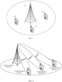
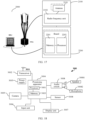
- FIG. 1 is a possible schematic diagram of an application scenario according to an embodiment of the present invention.
- a communication system in the application scenario includes a network device 10 and at least one terminal device 20.
- the network device 10 and the terminal device 20 may communicate through one or more air interface technologies.
- Air interface transmission includes uplink transmission and downlink transmission.
- uplink transmission means that the terminal device 20 sends uplink information to the network device 10.
- a channel used to transmit the uplink information is referred to as an uplink channel, and the uplink channel may be a physical uplink shared channel (physical uplink shared channel, PUSCH) or a physical uplink control channel (physical uplink control channel, PUCCH).
- the PUSCH is used to carry uplink data, and the uplink data may also be referred to as uplink data information.
- downlink transmission means that the network device 10 sends downlink information to the terminal device 20.
- a channel for transmitting the downlink information is referred to as a downlink channel.
- the downlink channel may be a physical downlink shared channel (physical downlink shared channel, PDSCH) or a physical downlink control channel (physical downlink control channel, PDCCH).
- the PDCCH is used to carry downlink control information (downlink control information, DCI).
- the PDSCH is used to carry downlink data, which may also be referred to as downlink data information.
- the network architecture shown in FIG. 1 may further include a core network device 30.
- the terminal device 20 may be connected to the network device 10 in a wireless manner, and the network device 10 may be connected to the core network device 30 in a wired or wireless manner.
- the core network device 30 and the network device 10 may be independent and different physical devices, or the core network device 30 and the network device 10 may be the same physical device, and all/part of the logical functions of the core network device 30 and the network device 10 are integrated on the physical device.
- the terminal device 20 may be at a fixed location, or may be movable. This is not limited.
- the application scenario shown in FIG. 1 may further include other network devices, such as wireless relay devices and wireless backhaul devices. This is not limited.
- quantities of terminal devices, network devices, and core network devices are not limited.
- Technical solutions in embodiments of this application may be applied to various communication systems, for example, a long term evolution (long term evolution, LTE) system, a 5 th generation (5 th generation, 5G) mobile communication system, or a future mobile communication system.
- LTE long term evolution
- 5G 5 th generation
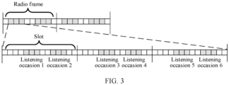
- FIG. 2 is a schematic diagram of beam sweeping.
- a communication device 1 in FIG. 2 may be the network device in the application scenario in FIG. 1
- communication devices 2 to 4 in FIG. 2 may be the terminal devices in the application scenario in FIG. 1 .
- a quantity of communication devices and a quantity of beams in FIG. 2 are merely examples. This is not limited in this application.
- Beam sweeping is a technology for transmitting beams along all predefined directions at regular intervals.
- the network device transmits the beam in different directions at different moments through time-division sweeping.
- the terminal device selects, through beam training, an SSB with best signal quality to complete synchronization and system information demodulation, and accesses a corresponding cell.
- the terminal device works on a specific beam selected by the terminal device through beam training.
- the terminal device can most efficiently receive downlink information sent by the network device and/or send uplink information to the network device.
- the terminal device cannot efficiently receive the downlink information sent by the network device.
- a communication device 4 is a network device, and the communication devices 1 to 3 are terminal devices.
- the following describes beam sweeping.
- a network device determines information about a beam used for beam sweeping, and sends the information about the beam to a terminal device.
- the network device when performing beam sweeping, notifies, by using a synchronization signal block PositionsInBurst (Synchronization Signal block PositionsInBurst, ssb-PositionsInBurst) in a system information block (system information block, SIB) 1 (SIB1 for short), the terminal device of the information about the beam used for beam sweeping.
- the ssb-PositionsInBurst indicates a time domain location of each synchronization signal block (Synchronization Signal block, SS-block) in a synchronization signal burst (Synchronization Signal burst, SS-burst), which may be understood as a time domain location of each beam in a beam sweeping process.
- ssb-PositionsInBurst when synchronization signal/physical broadcast channel blocks (Synchronization Signal/Physical Broadcast Channel blocks, SS/PBCH blocks) in each half-frame are different, the usage of information elements (Information Element, IE) contained in ssb-PositionsInBurst is also different.
- Information Element, IE Information Element
- ssb-PositionsInBurst includes only an IE inonegroup (inOneGroup), and the inOneGroup is an 8-bit bit map (bit map).
- the maximum quantity of SS/PBCH blocks in each half-frame is 4, only the leftmost four bits are valid, and the remaining four bits are invalid.
- a first or leftmost bit corresponds to an SS/PBCH block or a beam index 0
- a second bit corresponds to an SS/PBCH block or a beam block index 1, and so on.
- the 8-bit bit map is [1 0 1 1 0 0 0 0 0]
- the network device configures a control resource set CORESET and a search space (search space) that are of a PDCCH monitoring occasion, and sends configuration information of the control resource set CORESET and the search space to the terminal device.
- the monitoring occasion is a monitoring occasion corresponding to L beams.
- L is a quantity of beams actually used by the network device to perform beam sweeping in the cell to which the terminal device belongs, and is indicated by ssb-PositionsInBurst.
- the terminal device determines the monitoring occasion, or referred to as a time-frequency location of the monitoring occasion, based on the configuration information of the control resource set CORESET and the search space.
- the terminal device performs monitoring based on a PDCCH monitoring occasion indicated by the CORESET and the search space, to obtain DCI carried by the PDCCH.
- the DCI is scrambled by using an RNTI, and the RNTI herein may be a first RNTI.
- the monitoring occasion is also referred to as a PDCCH monitoring occasion. In this application, the monitoring occasion is used as an example for description.
- S202 The network device sends downlink information to the terminal device by using the beam.
- the network device transmits beams along all predefined directions at regular intervals in a beam sweeping manner.
- a transmission sequence of a plurality of beams is in ascending order of beam index values, and the beams may carry the downlink control information DCI carried by the PDCCH.
- the terminal device receives the information by using a specific beam, and listens to, at the time-frequency location of the PDCCH monitoring occasion, the downlink control information DCI carried by the PDCCH.
- the network device actually sends three beams in the cell to which the terminal device belongs, and index values are 0, 2, and 3 respectively.
- the network device sweeps the beams starting from the beam whose index is 0, followed by the beam whose index is 2 and the beam whose index is 3, and cycles based on the beam.
- the specific beam of the terminal device may be determined in a beam training manner.
- the network device sends a plurality of beams in a beam sweeping manner, for a terminal device at a specific location, only one or several beams in a specific direction can cover the terminal device.
- the terminal device measures the beams that can cover the terminal device, selects a beam with best signal quality as a specific beam corresponding to the terminal device, and reports information about the beam to the network device in a random access process. In this way, the network device and the terminal device transmit uplink and/or downlink information by using the specific beam.
- the terminal device and the network device determine a specific beam as a beam for information transmission between the network device and the terminal device.
- the terminal device can efficiently receive the downlink information sent by the network device and/or send the uplink information to the network device only when the terminal device sweeps a specific beam selected by the terminal device through beam training.
- the terminal device cannot efficiently receive the downlink information sent by the network device, and cannot efficiently send the uplink information to the network device.
- a beam training result is shown in FIG. 2 .
- An example in which a beam 1 corresponds to a communication device 1 is used.
- the communication device 1 can efficiently receive the downlink information sent by the communication device 4 and/or send the uplink information to the communication device 4 only when the beam 1 is swept.
- the communication device 1 cannot efficiently receive the downlink information from the communication device 4, and cannot efficiently send the uplink information to the communication device 4.
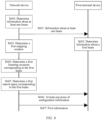
- the one or more terminal devices For one or more terminal devices that listen to downlink control information DCI carried by a PDCCH, the one or more terminal devices need to listen at a time-frequency location of a monitoring occasion in a search space. It can be learned from the foregoing description that both the beam and the monitoring occasion have time domain locations. Therefore, for a terminal device, when a time-frequency location of a PDCCH listened by the terminal device corresponds to a time domain location of a specific beam of the terminal device, that is, when the specific beam of the terminal device transmits information on a monitoring occasion listened by the terminal device, the terminal device can successfully listen to DCI carried by the PDCCH. Monitoring occasions in a search space are shown in FIG. 3 .
- Each radio frame includes a plurality of slots, each slot includes a plurality of symbols, and each monitoring occasion occupies one or more symbols.
- FIG. 3 shows an example in which each monitoring occasion occupies three symbols.
- the communication device 4 is a network device
- the communication device 1 to the communication device 3 are terminal devices 1 to 3, and the network device actually sends three beams in cells to which the three terminal devices belong.
- a specific beam of the terminal device 1 is a beam 1
- a specific beam of the terminal device 2 is a beam 2
- a specific beam of the terminal device 3 is a beam 3. All PDCCH monitoring occasions in FIG.
- All the foregoing monitoring occasions may also be monitoring occasions corresponding to one or more radio network temporary identifiers (Radio Network Temporary Identifier, RNTI) or a PDCCH. All the foregoing monitoring occasions are configured by the network device, configuration information of all the monitoring occasions is sent by the network device to three terminal devices, and the three terminal devices perform monitoring on the PDCCH monitoring occasions in FIG. 3 based on the configuration information of all the monitoring occasions, to obtain downlink control information DCI carried by the PDCCH.
- radio network temporary identifiers Radio Network Temporary Identifier, RNTI
- All the foregoing monitoring occasions are configured by the network device, configuration information of all the monitoring occasions is sent by the network device to three terminal devices, and the three terminal devices perform monitoring on the PDCCH monitoring occasions in FIG. 3 based on the configuration information of all the monitoring occasions, to obtain downlink control information DCI carried by the PDCCH.
- the terminal device when a time domain location of the beam 1 corresponds to a time domain location of the monitoring occasion on which the terminal device 1 performs monitoring, the terminal device can successfully listen to information transmitted on the monitoring occasion, and receive DCI carried by the PDCCH. It can be learned from the foregoing description that a correspondence, in other words, a mapping relationship, needs to be formed between a time domain location of a beam on which beam sweeping is performed and a time domain location of a PDCCH monitoring occasion, so that the network device can successfully send downlink control information DCI carried by the PDCCH.
- the terminal device performs monitoring on a monitoring occasion corresponding to a specific beam of the terminal device, so that the terminal device can successfully receive DCI that is sent by the network device and carried by the PDCCH.
- scheduling information of the service may be DCI that is carried by a PDCCH and that is scrambled by using an RNTI corresponding to multicast/multicast.
- a PDCCH monitoring occasion may be configured by the network device, but the PDCCH monitoring occasion does not correspond to a beam on which beam sweeping is performed in time domain.
- monitoring in this case cannot successfully or efficiently receive downlink information, and overheads of the terminal device are increased, causing power consumption.
- this application provides an information transmission method.
- a monitoring occasion is used to represent a PDCCH monitoring occasion
- an MBS is used to represent a multimedia broadcast multicast/multicast broadcast service for detailed description.
- a principle of the method is as follows: A first RNTI mapping period is configured, and a mapping relationship between a monitoring occasion of the first RNTI and a beam is established in the mapping period.
- a network device sends a target beam on a target monitoring occasion in the first RNTI mapping period, and a terminal device listens to, on the target monitoring occasion by using the target beam, first information scrambled by using the first RNTI, thereby improving monitoring efficiency of the terminal device, reducing resource overheads, and ensuring accuracy and efficiency of multicast/multicast MBS service transmission.
- a monitoring occasion of MBS service scheduling information forms a mapping relationship with a beam for transmitting the MBS service scheduling information.
- the first information may include control information, the control information is used to schedule a group of terminal devices to receive the MBS service, and the first RNTI may be a group RNTI (Group RNTI, G-RNTI).
- a monitoring occasion of system information scheduling information and a beam for transmitting the system information scheduling information form a mapping relationship.
- the first information may include control information, the control information may be used to schedule a dedicated system information block, and the first RNTI may be a system information radio network temporary identifier SI-RNTI.
- the first RNTI may be a radio identifier (Change Notification) used to schedule a change of the control information of the MBS service. This is not limited in this application.
- a terminal device may be briefly referred to as a terminal, or referred to as user equipment (user equipment, UE), which is a device having a wireless transceiver function.
- the terminal device may be deployed on land, where the deployment includes indoor or outdoor, or handheld or vehicle-mounted deployment, may be deployed on water (for example, on a ship), or may be deployed in air (for example, on aircraft, an uncrewed aerial vehicle, a balloon, or a satellite).
- the terminal device may be a mobile phone, a tablet computer, a computer having a wireless transceiver function, a virtual-reality terminal device, an augmented-reality terminal device, a wireless terminal device in industrial control, a wireless terminal device in self-driving, a wireless terminal device in telemedicine, a wireless terminal device in a smart grid, a wireless terminal device in transportation safety, a wireless terminal device in a smart city, or a wireless terminal device in a smart home.
- the terminal device may be fixed or mobile. This is not limited in embodiments of this application.
- an apparatus configured to implement a function of the terminal may be a terminal device, or may be an apparatus, for example, a chip system, that can support the terminal device in implementing the function.
- the apparatus may be installed in the terminal device.
- the chip system may include a chip, or may include a chip and another discrete component.
- a network device may be an access network device.
- the access network device may also be referred to as a radio access network (radio access network, RAN) device, and is a device that provides a wireless communication function for the terminal device.
- the access network device includes, for example, but is not limited to, a next generation NodeB (generation NodeB, gNB), an evolved NodeB (evolved NodeB, eNB), a baseband unit (baseband unit, BBU), a transmitting and receiving point (transmitting and receiving point, TRP), or a transmitting point (transmitting point, TP) in 5G, a base station in a future mobile communication system, or an access point in a Wi-Fi system.
- generation NodeB generation NodeB
- eNB evolved NodeB
- eNB baseband unit
- BBU baseband unit
- TRP transmitting and receiving point
- TP transmitting point
- the access network device may be a radio controller, a centralized unit (centralized unit, CU), and/or a distributed unit (distributed unit, DU) in a cloud radio access network (cloud radio access network, CRAN) scenario, or the network device may be a relay station, a vehicle-mounted device, a network device in a future evolved PLMN network, or the like.
- a radio controller a centralized unit (centralized unit, CU), and/or a distributed unit (distributed unit, DU) in a cloud radio access network (cloud radio access network, CRAN) scenario
- the network device may be a relay station, a vehicle-mounted device, a network device in a future evolved PLMN network, or the like.
- the terminal device may communicate with a plurality of access network devices by using different technologies.
- the terminal device may communicate with an access network device supporting long term evolution (long term evolution, LTE), may communicate with an access network device supporting 5G, or may communicate with both an access network device supporting LTE and an access network device supporting 5G. This is not limited in embodiments of this application.
- LTE long term evolution
- 5G access network device supporting 5G
- an apparatus configured to implement functions of the network device may be a network device, or may be an apparatus, for example, a chip system, that can support the network device in implementing the functions.
- the apparatus may be installed in the network device.
- the technical solutions provided in embodiments of this application the technical solutions provided in embodiments of this application are described by using an example in which the apparatus configured to implement the function of the network device is the network device.
- Time units are time domain units used for data transmission, and may include time domain units such as a radio frame (radio frame), a subframe (subframe), a slot (slot), a mini-slot (mini-slot), and a time domain symbol (symbol).
- a time domain symbol may be referred to as a symbol for short.
- the time domain symbol may be an orthogonal frequency division multiplexing (orthogonal frequency division multiplexing, OFDM) symbol, or may be a discrete Fourier transform spread orthogonal frequency division multiplexing (discrete Fourier transform spread orthogonal frequency division multiplexing, DFT-s-OFDM) symbol.
- One radio frame may include 10 radio subframes, and one radio subframe may include one or more slots.
- a specific quantity of slots included in one subframe is related to a subcarrier space.
- SCS Subcarrier Space
- a time domain length of one slot is 1 ms.
- One slot includes 14 orthogonal frequency division multiplexing (Orthogonal Frequency Division Multiplexing, OFDM) symbols.
- OFDM Orthogonal Frequency Division Multiplexing
- a beam is a communication resource.
- the beam may be understood as signal strength distribution formed in different directions in space after a signal is sent by using an antenna.
- the beams may be used to transmit data channel information, control channel information, sounding signals, and the like.
- the network device may send same information or different information by using different beams.
- the network device After a beamforming technology is used, the network device needs to use a plurality of beams with different directions to completely cover a cell. Therefore, the network device generally sends downlink information in a beam sweeping manner. To be specific, the network device sends the downlink information to the terminal device by using beams with different directions.
- a broadcast beam SSB is used to control cell access.
- Each broadcast beam has a beam index.
- the broadcast beam index is a time sequence number, that is, each index corresponds to a broadcast beam sent in time division.
- the network device sends a plurality of synchronization signal blocks (SS/PBCH block) in a beam sweeping manner.
- the terminal device measures the SS/PBCH block, selects a beam with best quality as a beam corresponding to the terminal device, and notifies the network device of information about the selected beam. In this way, the network device and the terminal device perform data transmission by using the specific beam.
- the DRX mechanism means that the terminal device stops monitoring to a PDCCH channel within a period of time.
- DRX There are two types of DRX: IDLE DRX and ACTIVE DRX.
- IDLE DRX means discontinuous reception when the terminal device is in a sleep state. In this case, a fixed period is defined in a network, and the terminal device can achieve discontinuous reception.
- ACTIVE DRX means discontinuous reception when the terminal device is in a radio resource control (Radio Resource Control) connected mode (RRC-connected). In this case, the terminal device does not need to enter the RRC sleep mode to implement discontinuous reception, so that resource configuration can be optimized, and power consumption of the terminal device can be reduced.
- RRC Radio Resource Control
- the network device encapsulates, in a control resource set (Control Resource Set, CORESET), information such as a frequency band occupied by the PDCCH and a quantity of orthogonal frequency division multiplexing (Orthogonal Frequency Division Multiplexing, OFDM) symbols occupied in time domain, and encapsulates, in a search space (Search Space), information such as a number of a start OFDM symbol of the PDCCH and a monitoring period.
- the network device sends the configuration of the CORESET and the configuration of the search space to the terminal device.
- the terminal device obtains an effective location range of the PDCCH by learning the configuration information of the CORESET, and obtains the time-frequency location of the PDCCH in the CORESET by using the configuration information of the search space.
- the terminal device determines, by blindly detecting a search space in the CORESET, whether there is a PDCCH sent by the network device to the terminal device.
- the monitoring occasion of the search space is configured by using the following parameters:
- N slot frame , ⁇ is a quantity of slots in a radio frame
- n f represents a quantity of radio frames
- n s , f ⁇ represents a number of the first to-be-measured slot in the radio frame.
- a quantity of slots in a radio frame is 10
- a quantity of radio frames is 2
- a period of a search space is five slots
- an offset is one slot
- Multimedia broadcast multicast service Multimedia Broadcast Multicast Service, MBMS
- MBS multicast broadcast service
- a multimedia broadcast multicast service (Multimedia Broadcast Multicast Service, MBMS) or a multicast broadcast service (multicast broadcast service, MBS) is a service oriented to a plurality of terminal devices, for example, live streaming or scheduled program playing.
- a multicast transmission technology is a technology in which an MBS service simultaneously sends information to a plurality of terminal devices by using a base station.
- the MBS is between the network and the terminal device.
- the MBS may be sent to a terminal device in a unicast manner by establishing a dedicated bearer for the terminal device, or may be sent to a group of terminal devices in a broadcast manner by establishing a dedicated bearer for the MBS.
- the MBS service When a large quantity of terminal devices need to receive an MBS service, if the MBS service is sent in a unicast manner, a dedicated bearer needs to be set up for each terminal device in the large quantity of terminal devices, consuming a large quantity of resources. If the MBS service is sent to the terminal devices in a broadcast manner, only a dedicated MBS bearer needs to be set up.
- the base station receives the service from a core network, and then sends the service to the plurality of terminal devices in the broadcast manner.
- Radio network temporary identifier Radio Network Temporary Identifier, RNTI
- An RNTI is configured by the network device, and is used to identify a terminal device in a connected mode in a cell, a group of terminal devices in a paging scenario, a special radio channel, and/or the like.
- Different types of RNTIs work by scrambling a cyclic redundancy check (Cyclic Redundancy Check, CRC) part of radio channel downlink control information (Downlink Control Information, DCI).
- CRC Cyclic Redundancy Check
- DCI Downlink Control Information
- the DCI is carried on a physical downlink control channel (Physical Downlink Control Channel, PDCCH).
- PDCCH Physical Downlink Control Channel
- the network device configures a monitoring occasion for a PDCCH of the DCI scrambled by using the RNTI, and sends the configuration information to the terminal device.
- the terminal device obtains, by using the configuration information, a time-frequency range corresponding to the monitoring occasion of the PDCCH of the DCI scrambled by using the RNTI, and performs monitoring in the time-frequency range, to decode the DCI scrambled by using the RNTI.
- Multicast/Multicast control channel Multicast Control Channel, MCCH
- An MCCH is used to transmit MBS-related control information.
- MBMS-related logical channels include a broadcast control channel (Broadcast Control Channel, BCCH), an MCCH, and an MBMS point-to-multipoint control channel (MBMS point-to-multipoint Control Channel, MTCH).
- BCCH Broadcast Control Channel
- MCCH MBMS point-to-multipoint Control Channel
- the BCCH is used by the network device to broadcast system information to the terminal device.
- the MCCH is used by the network to transmit MBMS-related control information to the terminal device.
- One MCCH may correspond to one or more MTCHs. Only a terminal device that can read an MBMS service can use the MCCH.
- the network device notifies the terminal device of a modulation and coding scheme (Modulation and Coding Scheme, MCS) of the MCCH and related information through system broadcast.
- MCS Modulation and Coding Scheme
- the MTCH is a point-to-multipoint downlink channel, and is used by the network device to transmit MBS service information to the terminal device. Only a terminal device that can read the MBS service can use the MTCH, and information about the MTCH is indicated by an MCCH corresponding to the MTCH.
- the network device indicates the MCCH to the terminal device by using the BCCH, and then indicates the MTCH to the terminal device by using the MCCH, so that the terminal device reads the MBMS service carried on the MTCH.
- the MCCH described in this specification is, but is not limited to, a multicast/multicast control logical channel for short.
- At least one of the following items (pieces) or a similar expression thereof refers to any combination of these items, including any combination of singular items (pieces) or plural items (pieces).
- at least one item (piece) of a, b, or c may represent a, b, c, a and b, a and c, b and c, or a and b and c, where a, b, and c may be singular items (pieces) or plural items (pieces).
- a network device in FIG. 4 may be the access network device 10 in FIG. 1
- a terminal device may be the terminal device 20 in FIG. 1 .
- the method shown in FIG. 4 may include the following operations.
- S400 A network device determines information about at least one beam.
- the at least one beam is at least one beam sent by the network device in a cell to which a terminal device belongs, the information about the at least one beam includes a beam quantity L of the at least one beam and an index of each beam, and L is a positive integer.
- the network device sends the information about the at least one beam to a terminal device.
- the terminal device receives the information about the at least one beam.
- the information about the at least one beam is carried in a SIB1.
- the information about the at least one beam may be notified to the terminal device by using ssb-PositionsInBurst in the SIB1.
- ssb-PositionsInBurst in the SIB1.
- the terminal device determines information about a first beam.
- the first beam is used by the terminal device to receive information from the network device.
- the first beam is a specific beam that is selected by the terminal device through beam training and that is used to efficiently receive downlink information sent by the network device and/or send uplink information to the network device.
- the information about the first beam is an index value of the first beam
- the index value of the first beam may be understood as a location of the first beam in the L beams.
- the terminal device determines, in a beam training manner based on the received information about the at least one beam, that the first beam is a specific beam corresponding to the information among the L beams, and the terminal device determines the location of the first beam in the L beams based on the index value of the first beam.
- the location corresponds to a sequence of the first beam in a process of sweeping the L beams.
- the location of the first beam in the L beams may be represented by a sequence number of the first beam in a process of performing beam sweeping on the L beams.
- the network device determines a monitoring occasion of a first RNTI.
- the monitoring occasion of the first RNTI is a time-frequency resource that is configured by the network device and that is used by the terminal device to listen to DCI scrambled by using the first RNTI.
- first information in this embodiment may be the DCI or the first information may be carried in the DCI.
- the network device configures a control resource set CORESET of the monitoring occasion of the first RNTI and a search space corresponding to the CORESET, and the terminal device listens to, on the monitoring occasion of the first RNTI, information scrambled by using the first RNTI.
- the search space may be a search space configured by the network device for the monitoring occasion of the first RNTI, or may be a search space configured by the network device for all different RNTIs that schedule different MBS services, or may be a common search space (common search space).
- the monitoring occasion of the search space is a monitoring occasion that can be used to listen to the first RNTI.
- the monitoring occasion of the search space is a monitoring occasion of RNTIs that scramble DCI of all MBS services of a cell to which the terminal device belongs.
- the monitoring occasion of the common search space may include the monitoring occasion of the first RNTI, or may include a monitoring occasion of another RNTI. This is not limited herein.
- the first RNTI may be an identifier used to perform MBS service scheduling, or an RNTI used to scramble DCI for scheduling a group of terminal devices, for example, a G-RNTI; or may be an RNTI for scheduling a dedicated system information block, for example, an SI-RNTI; or the first RNTI may be a radio identifier used to schedule a change of MBS service control information.
- S404 The network device determines a mapping period of the first RNTI.
- the mapping period of the first RNTI is a parameter configured by the network device, and is used to form a mapping relationship between a beam for transmitting DCI scrambled by using the first RNTI and a monitoring occasion of the beam within duration indicated by the mapping period of the first RNTI. Specifically, the network device determines the mapping period of the first RNTI based on a quantity of beams sent for the cell to which the terminal device belongs and/or a quantity of monitoring occasions of the first RNTI; or the network device determines the mapping period of the first RNTI based on a configuration of the search space or another parameter. This is not limited herein.
- S405 The network device sends at least one piece of configuration information to the terminal device, and correspondingly, the terminal device receives the at least one piece of configuration information sent by the network device.
- the at least one piece of configuration information indicates the mapping period of the first RNTI and a first offset.
- the mapping period of the first RNTI and the first offset indicate a first mapping window.
- the first mapping window is duration within a first mapping period of the first RNTI.
- the first mapping period is any mapping period of the first RNTI
- the first mapping window is any mapping window of the first RNTI.
- the mapping period of the first RNTI and the first offset may indicate the first mapping window, and the mapping period of the first RNTI, the first offset, and the first mapping window meet a predefined rule.
- the predefined rule may indicate at least one time domain location, and the at least one time domain location may be used as a time domain start location at which a mapping relationship may be formed from a monitoring occasion of the L beams and the first RNTI, which is alternatively referred to as a time domain start location of at least one mapping window.
- a time domain location in the first mapping period in at least one time domain location indicated by the mapping period of the first RNTI and the first offset is the time domain start location of the first mapping window.
- the first offset indicates an offset between the time domain start location of the first mapping period and the time domain start location of the first mapping window.
- the time domain start location of the first mapping window meets a predefined rule.
- the time domain start location of the first mapping window includes a system frame number of the time domain start location and a slot number of the time domain start location.
- the system frame number and the slot number meet a predefined rule.
- Example 1 and Example 2 the formulas that the system frame number and the slot number of the time domain start location of the first mapping window meet are merely examples, and there may be variations of a plurality of formulas. This is not limited in this application.
- the first offset may be an offset of a search space, where the search space is a search space of the monitoring occasion of the first RNTI; or the first offset may be a dedicated offset configured by the network device for the first mapping window.
- the at least one piece of configuration information further indicates a period of the search space.
- the first offset not only indicates the offset between the time domain start location of the first mapping period and the time domain start location of the first mapping window in the first mapping period, in other words, indicates an offset between a time domain start location of each mapping period of the first RNTI and a time domain start location of a mapping window in each mapping period, but also indicates an offset between a time domain start location of each period of the search space and a start location of the search space in each period.
- the network device may configure the time domain start location of the first mapping window to overlap the time domain start location of the search space in at least one period of the search space.
- SFN and n Slot in the foregoing formula are a subset of SFN1 and n Slot1 .
- the network device may configure the duration of the first mapping period to be an integer multiple of the duration of the period of the search space.
- the network device may configure the duration of the period of the search space to be an integer multiple of the duration of the first mapping period.
- the network device may configure the mapping period of the first RNTI to be an integer multiple of the period of the search space, or the network device may configure the period of the search space to be an integer multiple of the mapping period of the first RNTI.
- FIG. 8 shows a case in which the duration of the first mapping period is an integer multiple of the duration of the period of the search space.
- FIG. 8 is merely an example. This is not limited in this application.
- the at least one piece of configuration information further indicates the period of the search space and a second offset of the search space, where the second offset indicates an offset between a time domain start location of each period of the search space and a start location of the search space in each period.
- the first offset is irrelevant to the second offset of the search space
- a start moment of the first mapping window does not need to be the same as a start moment of the search space
- the network device can configure the first mapping period and the offset more flexibly.
- FIG. 9 shows a case in which a network device configures a dedicated offset for a first mapping window.
- An example is used in which duration of a first mapping period is greater than one system frame number.
- FIG. 9 is merely an example. This is not limited in this application.
- the plurality of monitoring occasions are monitoring occasions that are in the first mapping window and that are in the monitoring occasions of the first RNTI.
- the plurality of beams are in a one-to-one correspondence, in ascending order of index values, with the plurality of monitoring occasions that are in the first mapping window and that start from the first monitoring occasion in time domain in time-domain order.
- the quantity of the plurality of monitoring occasions of the first RNTI in the first mapping window is greater than the quantity of beams sent by the network device in the cell to which the terminal device belongs, in other words, when the quantity of the plurality of monitoring occasions in the first mapping window is greater than the quantity of the plurality of beams, starting from a monitoring occasion corresponding to a next first RNTI after one round of mapping is completed, a one-to-one correspondence starts from a beam with a smallest index value, and cycles sequentially.
- the first beam and the first monitoring occasion are used as an example for detailed description.
- the one round of mapping means that the network device completes one round of beam sweeping on a premise that a plurality of beams are mapped to a plurality of monitoring occasions.
- S407 Determine a first monitoring occasion corresponding to the first beam.
- the first beam and the first monitoring occasion meet a first mapping relationship.
- the first monitoring occasion includes one or more monitoring occasions that are in the monitoring occasion of the first RNTI and that are in the first mapping window within the first mapping period and that meet the first mapping relationship with the first beam.
- the first monitoring occasion is a set of monitoring occasions that correspond to the first beam and that are in the first mapping window.
- the first mapping period is any mapping period of the first RNTI
- the first mapping window is duration that is located in the first mapping period and that is determined based on the mapping period of the first RNTI and the first offset.
- a sequence number of the first beam in the plurality of beams is K
- the sequence number K may represent a location of the first beam in the L beams.
- sequence numbers of a plurality of beams may start from 1.
- sequence numbers of the three beams are respectively 1, 2, and 3 in ascending order of beam index values.
- a sequence of the first monitoring occasion in the plurality of monitoring occasions is M.
- M may also be represented by a sequence number of the first monitoring occasion in the plurality of monitoring occasions.
- sequence numbers increase in ascending order.
- the start value of the sequence numbers may be any natural number.
- the start value of the sequence numbers is 0.
- the start value of the sequence numbers is 1.
- the start value of the sequence numbers is not limited herein.
- a sequence number of a monitoring occasion in the first mapping window starts from 1.
- the monitoring occasion is a monitoring occasion that meets the first mapping relationship with the beam.
- the beam is a first beam
- the monitoring occasion that meets the first mapping relationship with the beam is a first monitoring occasion.
- the monitoring occasion belongs to the first monitoring occasion.
- the first beam is a specific beam corresponding to the terminal device in the plurality of beams. In other words, the terminal device efficiently receives downlink information and/or efficiently sends uplink information to the network device by using the first beam.
- the foregoing described first mapping relationship between the first beam and the first monitoring occasion in the first mapping window may be further represented as:
- the terminal device determines a quantity m of monitoring occasions in the first mapping window.
- the terminal device may determine, based on a configuration of the search space of the first RNTI, a length of the first mapping window, and a time domain location, the quantity m of monitoring occasions in the first mapping window, that is, a total quantity of a plurality of monitoring occasions. For example, in FIG. 8 , the quantity m of monitoring occasions in the first mapping window is 10.
- K is the sequence number of the first beam in the plurality of beams, and in the first mapping window, a monitoring occasion corresponding to the K th beam is the [x ⁇ L+K] th monitoring occasion, that is, the monitoring occasion corresponding to the first beam is the [x ⁇ L+K] th monitoring occasion in the first mapping window.
- x 0, 1, ..., or X-1
- X CEIL (m/L), where CEIL indicates rounding up.
- K 1, 2, ..., or L, where L is a quantity of a plurality of beams, that is, a quantity of beams sent by the network device in the cell to which the terminal device belongs.
- the foregoing may also be expressed as follows:
- the first beam is a specific beam corresponding to the terminal device in the plurality of beams. In other words, the terminal device efficiently receives downlink information and/or efficiently sends uplink information to the network device by using the first beam.
- the formula that the first mapping relationship between the first beam and the first monitoring occasion meets and the sequence numbers of the first beam and the first monitoring occasion are merely examples.
- the formula corresponding to the first mapping relationship has a plurality of variations, and a form of the sequence number has a plurality of variations. This is not limited in this application.
- the network device configures corresponding beam transmission resources on the plurality of monitoring occasions based on the mapping relationship between the plurality of beams and the plurality of monitoring occasions in the first mapping window of the first RNTI.
- the terminal device performs monitoring on the first monitoring occasion based on the first mapping relationship between the first beam and the first monitoring occasion in the first mapping window of the first RNTI.
- the terminal device may perform monitoring on any one of the first monitoring occasions corresponding to the first beam, and does not perform monitoring on a monitoring occasion corresponding to another beam; or the terminal device performs monitoring on a plurality of or all of the first monitoring occasions corresponding to the first beam.
- the network device sends, on the first monitoring occasion corresponding to the first beam by using the first beam, first information scrambled by using the first RNTI to the terminal device.
- the terminal device listens, on the first monitoring occasion corresponding to the first beam, to the first information scrambled by using the first RNTI.
- the network device may determine the time domain locations of the plurality of monitoring occasions in the first mapping window based on the configuration information of the search space.
- the network device performs beam sweeping starting from the first monitoring occasion in time-domain order in the first mapping window. Specifically, starting from the first monitoring occasion in time-domain order in the first mapping window, the network device sequentially and cyclically sends the plurality of beams on each monitoring occasion in the first mapping window in time-domain order in ascending order of beam index values.
- the method includes: The network device sends, based on the first mapping relationship, the first information by using the first beam on the first monitoring occasion corresponding to the first beam, where the first information is scrambled by using the first RNTI.
- the terminal device may determine the time domain locations of the plurality of monitoring occasions in the first mapping window based on the configuration information of the search space.
- the terminal device may listen, on the first monitoring occasion based on the first mapping relationship between the first beam and the first monitoring occasion, to the first information transmitted by using the first beam, where the first information is scrambled by using the first RNTI.
- the first information is scrambled by using the first RNTI.
- the first information includes downlink control information scrambled by using the first RNTI.
- the downlink control information scrambled by using the first RNTI is used to schedule a group of terminal devices.
- the first RNTI is used to schedule MBS service data.
- the first RNTI may be a G-RNTI.
- the downlink control information is used to schedule a dedicated system information block.
- the first RNTI may be an SI-RNTI.
- the first RNTI may be a radio identifier used to schedule a change of MBS service control information.
- a specific beam selected by the terminal device through beam training is the first beam
- the terminal device determines a location of the first beam in the L beams by using index values of the L beams.
- the location may be represented by a sequence number K of the first beam in the L beams in a beam sweeping process.
- the terminal device may listen to the K th , the (K+L) th , the (K+2L) th , the (K+3L) th , the (K+4L) th ... monitoring occasions in the first mapping window in time-domain order.
- the terminal device may select, in the first mapping window, a monitoring occasion corresponding to any first beam for monitoring, and may obtain, without monitoring to a monitoring occasion corresponding to another beam, the first information that is transmitted by the first beam and that is scrambled by using the first RNTI.
- the terminal device may listen to a plurality of or all of first monitoring occasions corresponding to the first beam, to obtain the first information that is transmitted by the first beam and that is scrambled by using the first RNTI.
- a quantity of beams is 3, and index values are 0, 2, and 3 respectively. If the index value of the first beam is 0, the sequence number of the first beam in the three beams is 1.
- the search space located in the first mapping window includes 10 monitoring occasions, and starting from the start location of the first mapping window, sequence numbers of the 10 monitoring occasions in time-domain order are first to tenth.
- the network device sequentially and cyclically sends three beams starting from a monitoring occasion whose sequence number is 1.
- the first monitoring occasion corresponding to the first beam is the first monitoring occasion, the fourth monitoring occasion, the seventh monitoring occasion, and the tenth monitoring occasion in the foregoing 10 monitoring occasions, or monitoring occasions whose sequence numbers are 1, 4, 7, and 10.
- the network device sends the first information to the terminal device on the first monitoring occasion, the fourth monitoring occasion, the seventh monitoring occasion, and the tenth monitoring occasion by using the first beam.
- the terminal device may listen to the first information on the first monitoring occasion, the fourth monitoring occasion, the seventh monitoring occasion, and the tenth monitoring occasion, or the monitoring occasions whose sequence numbers are 1, 4, 7, and 10, without monitoring to another monitoring occasion in the foregoing 10 monitoring occasions. Further, the terminal device may select one, more, or all of the first monitoring occasion, the fourth monitoring occasion, the seventh monitoring occasion, and the tenth monitoring occasion to perform monitoring.
- the first beam and the first monitoring occasion form the first mapping relationship in the first mapping window.
- the network device and the terminal device transmit information
- the network device sends the first information to the terminal device on the first monitoring occasion by using the first beam. This avoids a problem that the network device does not send the first beam on the first monitoring occasion when configuring the first monitoring occasion by using the CORESET and the search space.
- the terminal device can listen to the first information on the first monitoring occasion by using the first beam, thereby avoiding invalid monitoring of the terminal device and improving monitoring efficiency.
- the method further includes: S408: The network device configures discontinuous reception (Discontinuous Reception, DRX).
- the network device configures DRX, to allow the terminal device to stop monitoring to the PDCCH/DCI on the monitoring occasion in a period of time. In other words, the terminal device does not need to listen to the PDCCH in a DRX inactive period.
- the DRX may be DRX configured by the network device for the first RNTI. In this case, the terminal device stops monitoring to DCI scrambled by using the first RNTI in a period of time.
- the DRX may be DRX configured by the network device for different RNTIs for scheduling all MBS services. In this case, the terminal device stops monitoring to DCI scrambled by using the different RNTIs in a period of time.
- the DCI includes DCI scrambled by using the first RNTI, or may include DCI scrambled by using another RNTI.
- the DRX may be DRX configured by the network device for the terminal device based on a type or a level of the terminal device.
- the DRX is DRX configured by the network device for the terminal device.
- the terminal device stops monitoring to the downlink control information DCI in a period of time indicated by the corresponding DRX.
- the DRX may be DRX configured by the network device based on a predefined definition. This is not limited in this application.
- the method further includes: S409: The network device sends DRX configuration information to the terminal device, and correspondingly, the terminal device receives the DRX configuration information.
- the DRX configuration information includes, but is not limited to, a DRX cycle, duration of an active period in the DRX cycle, and a third offset.
- a time domain start location of the active period in each DRX cycle is determined based on the DRX cycle and the third offset.
- the network device may configure duration of the active period to meet that the network device completes at least one round of beam sweeping.
- the method further includes: S410: The network device and the terminal device determine a start location of an active period in a DRX cycle.
- the network device and the terminal device can determine the time domain start location of the active period in each DRX cycle based on the DRX configuration information.
- the third offset indicates an offset between a time domain start location of each DRX cycle and a time domain start location of an active period in each cycle.
- the network device may configure the time domain start location of the active period in the DRX cycle to be the same as the time domain start location of the mapping window in the at least one first RNTI cycle.
- a subframe and a slot may be converted, and locations indicated by SFN2 and Subframe in the foregoing formula may be subsets of the SFN and the locations indicated by n Slot .
- the time domain start location of the active period coincides with at least one start location at which a plurality of beams and a plurality of monitoring occasions may start to form a mapping relationship. This helps improve monitoring efficiency and air interface resource utilization, and avoid a waste of resources.
- the time domain start location of the active period configured by the network device is the same as the time domain start location of the first mapping window.
- monitoring occasions that are simultaneously in the active period are monitoring occasions on which the terminal device may perform monitoring.
- the terminal device does not perform monitoring.
- the method further includes: S411: The network device and the terminal device determine a first monitoring sub-occasion.
- the network device and the terminal device may determine a time domain location of the first monitoring sub-occasion based on the determined time domain start location of the active period and the time domain location of the first monitoring occasion.
- the first monitoring sub-occasion is a set of one or more monitoring occasions that are in the active period of the DRX cycle and that are in the first monitoring occasion.
- monitoring occasions in the first mapping window there are seven monitoring occasions in the first mapping window, and the network device actually sends three beams in the cell to which the terminal device belongs.
- Beam indexes are respectively 0, 2, and 3.
- the beam whose index is 0 is a beam selected by the terminal device through beam training, that is, the first beam.
- monitoring occasions that meet the first mapping relationship with the first beam in the first mapping window are the first monitoring occasion, the fourth monitoring occasion, and the seventh monitoring occasions.
- the first monitoring occasion is the first monitoring occasion, the fourth monitoring occasion, and the seventh monitoring occasion in the first mapping window.
- the monitoring occasions in the active period are the first monitoring occasion and the fourth monitoring occasion.
- the first monitoring sub-occasions of the first monitoring occasion are the first monitoring occasion and the fourth monitoring occasion in the first mapping window.
- the method further includes: S412: The network device sends the first information to the terminal device on the first monitoring sub-occasion by using the first beam.
- the terminal device receives, on the first monitoring sub-occasion by using the first beam, the first information sent by the network device, where the first information is scrambled by using the RNTI.
- the first information is scrambled by using the first RNTI.
- the first information includes downlink control information scrambled by using the first RNTI.
- the downlink control information scrambled by using the first RNTI is used to schedule a group of terminal devices.
- the first RNTI is used to schedule MBS service data.
- the first RNTI may be a G-RNTI.
- the downlink control information is used to schedule a dedicated system information block.
- the first RNTI may be an SI-RNTI.
- the first RNTI may be a radio identifier used to schedule a change of MBS service control information.
- Example 1 Starting from the first monitoring occasion in the first mapping window of the first RNTI, the network device sequentially and cyclically sends a plurality of beams on the monitoring occasion in the first mapping window in time-domain order.
- the first monitoring occasions include the first monitoring sub-occasion and a second monitoring sub-occasion, where the second monitoring sub-occasion is a set of one or more monitoring occasions that are in the inactive period and that are in the first monitoring occasion.
- the network device sends the first beam on all monitoring occasions of the first monitoring occasion.
- the terminal device determines the first monitoring occasion corresponding to the first beam, and the terminal device listens to the first information on the first monitoring sub-occasion of the first monitoring occasion by using the first beam based on the DRX configuration information.
- the terminal device may choose not to perform monitoring, so that power consumption of monitoring to the PDCCH/DCI by the terminal device can be further reduced.
- Example 2 The network device determines a first monitoring sub-occasion corresponding to the first beam, and the network device sends the first information only on the first monitoring sub-occasion that is in the DRX active period and that is in the first monitoring occasion by using the first beam, but does not send the first information on the second monitoring sub-occasion in the inactive period by using the first beam.
- the terminal device listens to the first information on the first monitoring sub-occasion of the first monitoring occasion based on the DRX configuration information by using the first beam. However, the terminal device does not perform monitoring on the second monitoring sub-occasion in the inactive period, so that power consumption of monitoring to the DCI by the terminal device can be further reduced.
- FIG. 5 shows another information transmission method according to this application.
- the method may be performed by a terminal device and a network device, or may be performed by a chip in the terminal device and a chip in the network device.
- the network device in FIG. 5 may be the access network device 10 in FIG. 1
- the terminal device may be the terminal device 20 in FIG. 1 .
- the method shown in FIG. 5 may include the following operations.
- S500 A network device determines information about at least one beam.
- the at least one beam is a beam sent by the network device in a cell to which a terminal device belongs, the information about the at least one beam includes a quantity L of the at least one beam and an index of each beam, and L is a positive integer.
- the network device sends the information about the at least one beam to a terminal device.
- a first terminal device receives and determines the information about the at least one beam.
- the information about the at least one beam is carried in a SIB1.
- the information about the at least one beam may be notified to the terminal device by using ssb-PositionsInBurst in the SIB1.
- ssb-PositionsInBurst in the SIB1.
- the terminal device determines information about a first beam.
- the first beam is used by the first terminal device to receive information from the network device.
- the first beam is a specific beam that is selected by the terminal device through beam training and that is used to efficiently receive downlink information and/or send uplink information.
- the information about the first beam is an index value of the first beam, and the index value of the first beam may be understood as a location of the first beam in the L beams.
- the index value of the first beam may be understood as a location of the first beam in the L beams.
- the network device determines a monitoring occasion of a first RNTI.
- the monitoring occasion of the first RNTI is a time-frequency resource that is configured by the network device and that is used by the terminal device to listen to DCI scrambled by using the first RNTI, and the DCI is carried by a PDCCH.
- the network device configures a control resource set CORESET of the monitoring occasion of the first RNTI and a search space corresponding to the CORESET, and the terminal device listens to, on the monitoring occasion of the first RNTI, information scrambled by using the first RNTI.
- the monitoring occasion of the first RNTI is a set of monitoring occasions of the downlink control information scrambled by using the first RNTI.
- the search space may be a dedicated search space configured by the network device for the monitoring occasion of the first RNTI, or may be an MBS search space configured by the network device for the monitoring occasion of the RNTI of the DCI for scrambling all MBS services, or may be a common search space (common search spaces).
- MBS search space configured by the network device for the monitoring occasion of the RNTI of the DCI for scrambling all MBS services
- common search space common search spaces
- the network device sends at least one piece of configuration information to the terminal device, and correspondingly, the terminal device receives the at least one piece of configuration information sent by the network device.
- the configuration information indicates a period of a search space and an offset of the search space
- the search space is a search space of the monitoring occasion of the first RNTI.
- the network device configures discontinuous reception (Discontinuous Reception, DRX).
- the network device configures DRX, to allow the terminal device to stop monitoring to the DCI on the monitoring occasion in a period of time. Specifically, through the DRX configuration, the terminal device stops monitoring in a period of time.
- the DRX may be DRX corresponding to the first RNTI. Therefore, the terminal device stops monitoring, in a period of time (which may be understood as an inactive period) configured by using the DRX, the DCI scrambled by using the first RNTI. In other words, the monitoring occasion of the first RNTI is in an active period configured by using the DRX.
- the DRX may be DRX corresponding to all MBS services transmitted in the cell to which the terminal device belongs.
- the DRX is DRX corresponding to a G-RNTI, and a configuration of the DRX is applied to monitoring to DCI scrambled by using any G-RNTI. For example, through the configuration, the terminal device stops, in a period of time, monitoring to DCI that is used to schedule all MBS services and that is in the cell to which the terminal device belongs.
- the DRX may be DRX corresponding to an RNTI, and a configuration of the DRX is applied to monitoring to DCI scrambled by using any RNTI.
- the terminal device stops monitoring, in a period of time, DCI scrambled by using any RNTI, where the DCI includes DCI scrambled by using the first RNTI, and may further include DCI scrambled by using another RNTI.
- the DRX may alternatively be DRX corresponding to a type or a level of the terminal device.
- a type or a level of the terminal device there is a correspondence between a type or a level of the terminal device and a DRX configuration.
- the terminal device stops monitoring to the downlink control information DCI in a period of time indicated by the corresponding DRX configuration.
- DRX may be predefined or pre-configured, for example, agreed in a protocol, or configured by using higher layer signaling or physical layer signaling. This is not limited in this application.
- the network device sends DRX configuration information to the terminal device, and correspondingly, the terminal device receives the DRX configuration information.
- the DRX configuration information includes, but is not limited to, at least one of a DRX cycle, duration of an active period in the DRX cycle, and a third offset, where the third offset is an offset of the active period in the DRX cycle.
- a time domain start location of the active period in each DRX cycle is determined based on the DRX cycle and the third offset.
- S507 The network device and the terminal device determine a start location of an active period in a DRX cycle.
- the network device and the terminal device can determine the time domain start location of the active period in each DRX cycle based on the DRX configuration information.
- the third offset indicates an offset between a time domain start location of each DRX cycle and a time domain start location of an active period in each cycle.
- the network device may configure the time domain start location of the active period in the DRX cycle to be the same as the time domain start location of at least one search space. This helps improve monitoring efficiency.
- FIG. 11 is a schematic diagram of a relationship between a DRX cycle and a period of a search space. In this case, an active period in the DRX cycle overlaps a time domain start location of at least one search space.
- S508 Determine a first monitoring occasion corresponding to the first beam.
- the network device and the terminal device determine the time domain start location of the active period.
- the first beam and the first monitoring occasion meet the first mapping relationship, and the first monitoring occasion is a set of one or more monitoring occasions that are in the monitoring occasion of the first RNTI and that are in the active period in the at least one DRX cycle.
- each of the plurality of beams and a monitoring occasion corresponding to the plurality of beams meet a first mapping relationship, and the plurality of beams are beams sent by the network device in the cell to which the terminal device belongs, that is, the L beams described in S500.
- the plurality of monitoring occasions are monitoring occasions in the active period of the at least one DRX cycle in monitoring occasions of the first RNTI.
- the network device may configure duration of the active period to meet that the network device completes at least one round of beam sweeping.
- the network device sends first information to the terminal device on the first monitoring occasion by using the first beam.
- the terminal device receives, on the first monitoring occasion by using the first beam, the first information sent by the network device, where the first information is scrambled by using the RNTI.
- the network device may determine the time domain locations of the plurality of monitoring occasions in the active period based on the configuration information of the search space.
- the network device performs beam sweeping starting from the first monitoring occasion in time-domain order in the active period. Specifically, starting from the first monitoring occasion in time-domain order in the first mapping window, the network device sequentially and cyclically sends the plurality of beams on each monitoring occasion in the active period in time-domain order in ascending order of beam index values.
- the method includes: The network device sends, based on the first mapping relationship, the first information by using the first beam on the first monitoring occasion corresponding to the first beam, where the first information is scrambled by using the first RNTI.
- the terminal device may determine the time domain locations of the plurality of monitoring occasions in the active period based on the configuration information of the search space.
- the terminal device may listen, on the first monitoring occasion based on the first mapping relationship between the first beam and the first monitoring occasion, to the first information transmitted by using the first beam, where the first information is scrambled by using the first RNTI.
- the first information is scrambled by using the first RNTI.
- the first information includes downlink control information scrambled by using the first RNTI.
- the downlink control information scrambled by using the first RNTI is used to schedule a group of terminal devices.
- the first RNTI is used to schedule MBS service data.
- the first RNTI may be a G-RNTI.
- the downlink control information is used to schedule a dedicated system information block.
- the first RNTI may be an SI-RNTI.
- the first RNTI may be a radio identifier used to schedule a change of MBS service control information.
- a specific beam selected by the terminal device through beam training is the first beam
- the terminal device determines a location of the first beam in the L beams by using index values of the L beams.
- the location may be represented by a sequence number K of the first beam in the L beams in a beam sweeping process.
- the terminal device may listen to the K th , the (K+L) th , the (K+2L) th , the (K+3L) th , the (K+4L) th ... monitoring occasions in the active period in time-domain order.
- the terminal device may choose not to listen to a monitoring occasion corresponding to another beam in the active period.
- the terminal device may listen to one, a plurality of or all of first monitoring occasions corresponding to the first beam, to obtain the first information that is transmitted by the first beam and that is scrambled by using the first RNTI.
- a quantity of beams is 3, and index values are 0, 2, and 3 respectively. If the index value of the first beam is 0, the sequence number of the first beam in the three beams is 1.
- the search space located in the active period includes 10 monitoring occasions, and starting from the time domain start location of the active period, sequence numbers of the 10 monitoring occasions in time-domain order are first to tenth.
- the network device sequentially and cyclically sends three beams starting from a monitoring occasion whose sequence number is 1.
- the first monitoring occasion corresponding to the first beam is the first monitoring occasion, the fourth monitoring occasion, the seventh monitoring occasion, and the tenth monitoring occasion in the foregoing 10 monitoring occasions, or monitoring occasions whose sequence numbers are 1, 4, 7, and 10.
- the network device sends the first information to the terminal device on the first monitoring occasion, the fourth monitoring occasion, the seventh monitoring occasion, and the tenth monitoring occasion by using the first beam.
- the terminal device may listen to the first information on the first monitoring occasion, the fourth monitoring occasion, the seventh monitoring occasion, and the tenth monitoring occasion, or the monitoring occasions whose sequence numbers are 1, 4, 7, and 10, without monitoring to another monitoring occasion in the foregoing 10 monitoring occasions. Further, the terminal device may select one, more, or all of the first monitoring occasion, the fourth monitoring occasion, the seventh monitoring occasion, and the tenth monitoring occasion to perform monitoring.
- the first beam and the first monitoring occasion form the first mapping relationship in the active period.
- the network device and the terminal device transmit information
- the network device sends the first information to the terminal device on the first monitoring occasion by using the first beam. This avoids a problem that the network device does not send the first beam on the first monitoring occasion when configuring time-frequency information of the first monitoring occasion by using the CORESET and the search space.
- the terminal device listens to the first information on the first monitoring occasion by using the first beam, thereby avoiding invalid monitoring and improving monitoring efficiency.
- this application provides another information transmission method.
- the method may be performed by a first terminal device and a network device, or may be performed by a chip in the first terminal device and a chip in the network device.
- the network device in FIG. 6 may be the access network device 10 in FIG. 1
- the first terminal device may be the terminal device 20 in FIG. 1 .
- the method shown in FIG. 6 may include the following operations.
- S600 A network device determines information about at least one beam.
- the at least one beam is a beam sent by the network device in a cell to which a first terminal device belongs, the information about the at least one beam includes a quantity L of the at least one beam and an index of each beam, and L is a positive integer.
- the network device sends the information about the at least one beam to a first terminal device.
- the first terminal device receives and determines the information about the at least one beam.
- the information about the at least one beam is carried in a SIB1.
- the information about the at least one beam may be notified to the first terminal device by using ssb-PositionsInBurst in the SIB1.
- ssb-PositionsInBurst in the SIB1.
- the first terminal device determines information about a first beam.
- the first beam is used by the first terminal device to receive information from the network device.
- the first beam is a specific beam that is selected by the first terminal device through beam training and that is used to efficiently receive downlink information sent by the network device and/or send uplink information to the network device.
- the information about the first beam is an index value of the first beam
- the index value of the first beam may be understood as a location of the first beam in a plurality of beams.
- the first terminal device determines, in a beam training manner based on the received information about the at least one beam, that the first beam is a specific beam corresponding to the information among the L beams, and the first terminal device determines the location of the first beam in the L beams based on the index value of the first beam.
- the location corresponds to a sequence of the first beam in a process of sweeping the L beams.
- the location of the first beam in the L beams may be represented by a sequence number of the first beam in a process of performing beam sweeping on the L beams.
- S603 The network device determines a first mapping window. Further, the network device determines a time domain start location of the first mapping window.
- the network device determines a mapping period of a first RNTI and a first offset.
- the mapping period of the first RNTI and the first offset may indicate the first mapping window, and the mapping period of the first RNTI, the first offset, and the first mapping window meet a predefined rule.
- the predefined rule may indicate at least one time domain location, and the network device and the first terminal device use the at least one time domain location as a time domain start location at which a mapping relationship may be formed from a monitoring occasion of the L beams and the first RNTI, which is alternatively referred to as a time domain start location of at least one mapping window.
- a time domain location in the first mapping period in at least one time domain location indicated by the mapping period of the first RNTI and the first offset is the time domain start location of the first mapping window.
- the first offset indicates an offset between the time domain start location of the first mapping period and the time domain start location of the first mapping window.
- the time domain start location of the first mapping window meets a predefined rule.
- the time domain start location of the first mapping window includes a system frame number of the time domain start location and a slot number of the time domain start location.
- the system frame number and the slot number meet a predefined rule.
- the predefined rule refer to related descriptions in step S406 in FIG. 4 . Details are not described herein again.
- the first offset may be an offset of a search space, where the search space is a search space of the monitoring occasion of the first RNTI; or the first offset may be a dedicated offset configured by the network device for the first mapping window.
- the specific configuration refer to related descriptions in step S406 in FIG. 4 . Details are not described herein again.
- the network device determines a first monitoring occasion corresponding to the first beam.
- the first beam and the first monitoring occasion meet a first mapping relationship
- the first monitoring occasion is a set of one or more monitoring occasions that are in the monitoring occasions of the first RNTI and that are in the first mapping window within the first mapping period and that meet the first mapping relationship with the first beam
- the monitoring occasion of the first RNTI is a set of monitoring occasions of downlink control information scrambled by using the first RNTI.
- the first mapping period is any mapping period of the first RNTI
- the first mapping window is duration that is located in the first mapping period and that is determined based on the mapping period of the first RNTI and the first offset.
- the plurality of beams are in a one-to-one correspondence, in ascending order of index values, with the plurality of monitoring occasions that are in the first mapping window and that start from the first monitoring occasion in time domain in time-domain order.
- the quantity of the plurality of monitoring occasions of the first RNTI in the first mapping window is greater than the quantity of beams sent by the network device in the cell to which the first terminal device belongs, in other words, when the quantity of the plurality of monitoring occasions in the first mapping window is greater than the quantity of the plurality of beams, starting from a monitoring occasion corresponding to a next first RNTI after one round of mapping is completed, a one-to-one correspondence starts from a beam with a smallest index value, and cycles sequentially.
- the first beam and the first monitoring occasion are used as an example for detailed description.
- the one round of mapping means that one round of beam sweeping is completed on a premise that a plurality of beams are mapped to a plurality of monitoring occasions.
- step S406 in FIG. 4 Details are not described herein again.
- a sequence number of the first beam in the plurality of beams is K
- the sequence number K may represent a location of the first beam in the L beams.
- sequence numbers of a plurality of beams may start from 1.
- sequence numbers of the three beams are respectively 1, 2, and 3 in ascending order of beam index values.
- a sequence of the first monitoring occasion in the plurality of monitoring occasions is M.
- M may also be represented by a sequence number of the first monitoring occasion in the plurality of monitoring occasions.
- sequence numbers increase in ascending order.
- the start value of the sequence numbers may be any natural number.
- the start value of the sequence numbers is 0.
- the start value of the sequence numbers is 1.
- the start value of the sequence numbers is not limited herein.
- a sequence number of a monitoring occasion in the first mapping window starts from 1.
- the monitoring occasion is a monitoring occasion that meets the first mapping relationship with the beam.
- the beam is a first beam
- the monitoring occasion that meets the first mapping relationship with the beam is a first monitoring occasion.
- the monitoring occasion belongs to the first monitoring occasion.
- the first beam is a specific beam corresponding to the first terminal device in the plurality of beams. In other words, the first terminal device efficiently receives downlink information and/or efficiently sends uplink information to the network device by using the first beam.
- the foregoing described first mapping relationship between the first beam and the first monitoring occasion in the first mapping window may be further represented as:
- the first terminal device determines a quantity m of monitoring occasions in the first mapping window.
- the first terminal device may determine, based on a configuration of the search space of the first RNTI, a length of the first mapping window, and a time domain location, the quantity m of monitoring occasions in the first mapping window, that is, a total quantity of a plurality of monitoring occasions.
- the quantity m of monitoring occasions in the first mapping window is 10.
- K is the sequence number of the first beam in the plurality of beams, and in the first mapping window, a monitoring occasion corresponding to the K th beam is the [x ⁇ L+K] th monitoring occasion, that is, the monitoring occasion corresponding to the first beam is the [x ⁇ L+K] th monitoring occasion in the first mapping window.
- x 0, 1, ..., or X-1
- X CEIL (m/L), where CEIL indicates rounding up.
- K 1, 2, ..., or L, where L is a quantity of a plurality of beams, that is, a quantity of beams sent by the network device in the cell to which the first terminal device belongs.
- the foregoing may also be expressed as follows:
- the first beam is a specific beam corresponding to the first terminal device in the plurality of beams. In other words, the first terminal device efficiently receives downlink information and/or efficiently sends uplink information to the network device by using the first beam.
- the formula that the first mapping relationship between the first beam and the first monitoring occasion meets and the sequence numbers of the first beam and the first monitoring occasion are merely examples.
- the formula corresponding to the first mapping relationship has a plurality of variations, and a form of the sequence number has a plurality of variations. This is not limited in this application.
- the network device determines a first search space corresponding to the first beam.
- the network device may determine, based on a mapping relationship between a plurality of beams and a plurality of monitoring occasions in the first mapping window, a monitoring occasion corresponding to each of the L beams.
- the network device configures a search space for each of the L beams, and the L beams correspond to L search spaces.
- the L search spaces are configured in a unit of a slot. For example, duration of the search space in each period of the L search spaces is one slot, and monitoring occasions corresponding to each beam are at different locations in one slot, or it is understood that monitoring occasions corresponding to different beams occupy different symbols in one slot.
- the L beams are beams actually sent by the network device in the cell to which the first terminal device belongs in step S600. Each beam corresponds to one terminal device, and each beam corresponds to one search space. An example in which the first beam corresponds to the first terminal device and the first beam corresponds to the first search space is used for detailed description.
- the network device determines, based on a first mapping relationship that the first beam and the first monitoring occasion meet, the search space corresponding to the first monitoring occasion as the first search space. Because the first beam corresponds to the first monitoring occasion, the first monitoring occasion also corresponds to the first terminal device that uses the first beam as a specific beam in this case, and the first terminal device listens to the first RNTI by using the first search space. It may also be understood that the monitoring occasion determined by the first search space corresponds to only the first beam.
- the network device configures the first search space for the first beam, and the network device determines the first monitoring occasion.
- the monitoring occasion of the first RNTI is a time-frequency resource that is configured by the network device and that is used by the terminal device to listen to downlink control information DCI scrambled by using the first RNTI, and the downlink control information DCI is carried by a PDCCH.
- the first search space may be configured in a plurality of possibilities.
- the first search space may be a search space that corresponds to the first beam and that is in the search space configured by the network device for the monitoring occasion of the first RNTI.
- all monitoring occasions in the first search space are the monitoring occasions of the first RNTI.
- the first search space may be a search space that is in the common search space and that corresponds to the first beam.
- the monitoring occasion in the first search space includes a monitoring occasion of the first RNTI, and may further include a monitoring occasion of another RNTI.
- the first search space may be a search space that corresponds to the first beam and that is in search spaces configured by the network device for different RNTIs scheduling different MBS services.
- the monitoring occasions in the first search space are monitoring occasions of RNTIs scrambling DCI of all MBS services of the cell of the first terminal device.
- the first RNTI may be an identifier used to perform MBS service scheduling, for example, a G-RNTI; or may be an RNTI for scheduling a dedicated system information block, for example, an SI-RNTI; or the first RNTI may be a radio identifier used to schedule a change of MBS service control information.
- the network device determines the search space corresponding to the first monitoring occasion as the first search space.
- the monitoring occasion of the first search space corresponds only to the first beam.
- the first terminal device listens, in the first search space, to the downlink control information scrambled by using the first RNTI.
- the network device sends three beams in the cell to which the first terminal device belongs, where beam index values are 0, 2, and 3 respectively.
- the first beam corresponds to the beam whose index is 0,
- the second beam corresponds to the beam whose index is 2
- the third beam corresponds to the beam whose index is 3.
- One slot includes 14 symbols and corresponds to five monitoring occasions, and each monitoring occasion occupies two symbols.
- the first monitoring occasion in time-domain order corresponds to the first beam
- the second monitoring occasion corresponds to the second beam
- the third monitoring occasion corresponds to the third beam
- the fourth monitoring occasion corresponds to the first beam
- the fifth monitoring occasion corresponds to the second beam.
- Each beam corresponds to one search space.
- the network device determines, by using a correspondence between a beam and a monitoring occasion in one slot, a search space corresponding to each of the three beams.
- the first beam corresponds to a first search space
- a monitoring occasion of the first search space is a monitoring occasion corresponding to the first beam, that is, the first monitoring occasion and the fourth monitoring occasion.
- the second beam corresponds to a second search space
- a monitoring occasion of the second search space is a monitoring occasion corresponding to the second beam, that is, the second monitoring occasion and the fifth monitoring occasion.
- the third beam corresponds to a third search space, and a monitoring occasion of the third search space is a monitoring occasion corresponding to the third beam, that is, the third monitoring occasion.
- the network device sends at least one piece of configuration information to the first terminal device, and correspondingly, the first terminal device receives the at least one piece of configuration information sent by the network device.
- the at least one piece of configuration information includes configuration information of the first search space, for example, at least one of a period of the first search space, an offset of the first search space, duration of the first search space, or location information of the first monitoring occasion.
- the location information of the first monitoring occasion is a symbol that needs to be listened in each slot of the first search space, or the location information of the first monitoring occasion may be at least one symbol number occupied by the first monitoring occasion in one slot of the first search space.
- the period of the first search space and the offset of the first search space refer to related descriptions in step S406 in FIG. 4 . Details are not described herein again.
- the at least one piece of configuration information is carried in a system message.
- the information about the first monitoring occasion is carried in a system information block 1 (SIB1), or the information about the first monitoring occasion is carried in another system information block (another SIB).
- SIB1 system information block 1
- another SIB another system information block
- the information about the first monitoring occasion may be notified by the network device to the first terminal device in a broadcast manner, and the first terminal device receives the information about the first monitoring occasion through broadcast.
- the first search space may be configured by using the SIB1 or the another system information blocks (other SIBs); or may be configured by using a multicast logical channel, for example, an MCCH; or may be configured by using dedicated radio resource control (Radio Resource Control, RRC) information, for example, RRC release. This is not limited herein.
- the network device sends first information to the terminal device on the first monitoring occasion by using the first beam.
- the terminal device listens to the first information on the first monitoring occasion.
- the network device sends the first beam on the first monitoring occasion of the first search space.
- the terminal device receives the first information on the first monitoring occasion of the first search space based on the at least one piece of configuration information by using the first beam.
- the first information is scrambled by using the first RNTI.
- the first information is downlink control information scrambled by using the RNTI.
- the downlink control information is used to schedule a group of terminal devices.
- the first RNTI is used to schedule MBS service data.
- the first RNTI may be a group RNTI G-RNTI.
- the downlink control information is used to schedule a dedicated system information block.
- the first RNTI may be an SI-RNTI.
- the first RNTI may be a radio identifier used to schedule a change of MBS service control information.
- the first terminal device corresponds to the first beam
- the second terminal device corresponds to the second beam
- the third terminal device corresponds to the third beam.
- the location information of the first monitoring occasion is [1 1 0 0 0 0 0 0 0 0 1 1 0 0 0].
- the location information of the first monitoring occasion indicates that the first monitoring occasion occupies the first, second, tenth, and eleventh symbol number in one slot of the first search space.
- the first terminal device listens to the first information at locations of the first, second, tenth, and eleventh symbol numbers in one slot of the first search space based on the location information of the first monitoring occasion.
- location information of a monitoring occasion corresponding to the second beam is [0 0 0 1 1 0 0 0 0 0 0 0 1 1] in this case, and the second terminal device listens to the first information at locations of the third, fourth, thirteenth, and fourteenth symbol numbers in one slot of the second search space.
- location information of a monitoring occasion corresponding to the third beam is [0 0 0 0 0 0 0 1 1 0 0 0 0 0 0 0] in this case, and the third terminal device listens to the first information at locations of the seventh and the eighth symbol numbers in one slot of the third search space.
- the network device configures the first search space for the first beam, and the network device configures the transmission resource of the first beam on the first monitoring occasion of the first search space, thereby improving a resource transmission success rate.
- the first terminal device listens to the first information on the first monitoring occasion of the first search space, thereby avoiding invalid monitoring. Further, the first terminal device may select any one or more, or all of the first monitoring occasions to perform monitoring, instead of monitoring to a monitoring occasion of a search space corresponding to another beam.
- FIG. 7 shows another information transmission method according to this application.
- the method may be performed by a terminal device and a network device, or may be performed by a chip in the terminal device and a chip in the network device.
- a network device in FIG. 7 may be the access network device 10 in FIG. 1
- a terminal device may be the terminal device 20 in FIG. 1 .
- the method shown in FIG. 7 may include the following operations.
- a network device determines information about at least one beam.
- the at least one beam is a beam sent by the network device in a cell to which a terminal device belongs, the information about the at least one beam includes a quantity L of the at least one beam and an index of each beam, and L is a positive integer.
- the network device sends the information about the at least one beam to a terminal device.
- the terminal device receives and determines the information about the at least one beam.
- the information about the at least one beam is carried in a SIB1.
- the information about the at least one beam may be notified to the terminal device by using ssb-PositionsInBurst in the SIB1.
- ssb-PositionsInBurst in the SIB1.
- the terminal device determines information about a first beam.
- the first beam is used by the terminal device to receive information from the network device.
- the first beam is a specific beam that is selected by the terminal device through beam training and that is used to efficiently receive downlink information and/or send uplink information.
- the information about the first beam is an index value of the first beam
- the index value of the first beam may be understood as a location of the first beam in the L beams.
- the terminal device determines, in a beam training manner based on the received information about the at least one beam, that the first beam is a specific beam corresponding to the information among the L beams, and the terminal device determines the location of the first beam in the L beams based on the index value of the first beam.
- the location corresponds to a sequence of the first beam in a process of sweeping the L beams.
- the location of the first beam in the L beams may be represented by a sequence number of the first beam in a process of performing beam sweeping on the L beams.
- the network device configures a multicast/multicast control logical channel (Multicast Control Channel, MCCH).
- MCCH Multicast Control Channel
- the MCCH is a multicast/multicast control logical channel, and is used to transmit multicast/multicast control information.
- the MCCH configuration may include, but is not limited to, a repetition period (repetition period) of the MCCH, a fourth offset (Offset), and an MCCH modification period (Modification Period), and may further include at least one of a start boundary of the MCCH period, a first subframe (First Subframe) for scheduling the MCCH, and duration (duration) for scheduling the MCCH starting from the first subframe.
- a repetition period repetition period
- Offset fourth offset
- Modification Period Modification Period
- the fourth offset indicates an offset between a time domain start location of each repetition period of the MCCH and a time domain location of MCCH transmission.
- FIG. 13 is a schematic diagram of a relationship between configuration parameters of the MCCH.
- the network device configures an MCCH mapping period and a fifth offset.
- the MCCH mapping period is used to form a mapping relationship between a beam and a time domain transmission location of the MCCH. In other words, at the time domain transmission location of the MCCH configured in the network, a corresponding beam is used to transmit the MCCH to the terminal device.
- the first MCCH mapping period and the fifth offset indicate a second mapping window. Specifically, as shown in FIG.
- the fifth offset indicates an offset between a time domain start location of the first MCCH mapping period and a time domain start location of the second mapping window, and the first MCCH mapping period is any mapping period of the MCCH.
- the following uses an MCCH transmission location to represent a time domain transmission location of the MCCH for detailed description.
- the at least one piece of configuration information indicates configuration information of an MCCH, where the configuration information of the MCCH includes a repetition period (repetition period) of the MCCH, a fourth offset (Offset), and an MCCH modification period (Modification Period), and may further include a start boundary of the MCCH period, a first subframe (First Subframe) for scheduling the MCCH, and duration (duration) for scheduling the MCCH starting from the first subframe.
- the at least one piece of configuration information further indicates the MCCH mapping period and the fifth offset.
- S705 Determine a mapping relationship between a plurality of beams and a plurality of MCCH transmission locations.
- the mapping relationship is formed between the MCCH transmission locations and the beams in the second mapping window, and the second mapping window is duration.
- a mapping relationship is formed between an MCCH transmission location and a beam in the MCCH modification period.
- the MCCH modification period is the second mapping window.
- the second mapping window is indicated by the MCCH modification period
- a length of the second mapping window is the MCCH modification period.
- FIG. 14 shows an example in which the length of the second mapping window is the MCCH modification period.
- a mapping relationship is formed between the MCCH transmission location and the beam in the second mapping window indicated by the first MCCH mapping period and the fifth offset.
- a mapping relationship is formed between a beam and an MCCH transmission location in each modification period of the MCCH.
- the network device and the terminal device may determine a start location of the second mapping window based on the time domain start location of the MCCH modification period.
- the start location meets the system frame number SFN4 in the foregoing formula.
- the fourth offset indicates an offset between a time domain start location of each repetition period of the MCCH and a time domain location of MCCH transmission in each repetition period.
- a time domain start location of each MCCH in each repetition period may be determined, that is, the system frame number SFN3 in the foregoing formula is met.
- both the start location of the second mapping window and a time domain start location of each MCCH are known, and in the second mapping window, the network device forms a mapping relationship between a plurality of beams and a plurality of MCCH transmission locations in a beam sweeping manner.
- the network device configures an MCCH mapping period and a fifth offset.
- the MCCH mapping period and the fifth offset indicate the second mapping window.
- the fifth offset indicates an offset between the time domain start location of the first MCCH mapping period and the time domain start location of the second mapping window in the first MCCH mapping period, and the first MCCH mapping period is any mapping period of the MCCH.
- the time domain start location of the second mapping window meets a predefined rule.
- the time domain start location of the second mapping window includes a system frame number of the time domain start location and a slot number of the time domain start location. The system frame number and the slot number meet a predefined rule.
- a plurality of MCCHs in the second mapping window that is, a plurality of MCCH transmission locations.
- each of the plurality of beams and an MCCH transmission location corresponding to the plurality of beams meet a first mapping relationship, and the plurality of beams are beams sent by the network device in the cell to which the terminal device belongs, that is, the L beams described in S700.
- the plurality of MCCH transmission locations are MCCH transmission locations that are in the second mapping window and that are in the MCCH transmission locations.
- the plurality of beams in ascending order of index values are in a one-to-one correspondence with the plurality of MCCH transmission locations in the second mapping window in time-domain order.
- a quantity of the plurality of MCCH transmission locations in the second mapping window is greater than a quantity of beams sent by the network device in the cell to which the terminal device belongs, in other words, when the quantity of the plurality of MCCH transmission locations in the second mapping window is greater than the quantity of the plurality of beams, starting from a next transmission location corresponding to completion of a round, a one-to-one correspondence starts from a beam with a smallest index value, and cycles sequentially.
- the one round of mapping means that the network device completes one round of beam sweeping on a premise that a plurality of beams are mapped to a plurality of MCCH transmission locations.
- S706 Determine a first MCCH transmission location corresponding to the first beam.
- the first MCCH transmission location is a set of MCCH transmission locations corresponding to the first beam.
- the first MCCH transmission location is a set of MCCH transmission locations that are located in the second mapping window and that meet the first mapping relationship with the first beam.
- the first MCCH is an MCCH transmission location in the first MCCH transmission location.
- An MCCH transmission location is referred to as a first MCCH below.
- the terminal device determines the first MCCH transmission location corresponding to the first beam, and receives the MCCH at the first MCCH transmission location by using the first beam.
- a sequence number of the first beam in the plurality of beams is K
- the sequence number K may represent a location of the first beam in the L beams.
- sequence numbers of a plurality of beams may start from 1.
- an information indication of the at least one beam indicates that the network device actually sends three beams, and index values are 0, 2, and 3 respectively.
- ssb-PositionsInBurst in the SIB1, and a configuration of the inOneGroup IE included in the ssb-PositionsInBurst is [1 0 1 1 0 0 0 0].
- sequence numbers of the three beams are respectively 1, 2, and 3 in ascending order of beam index values. In this example, if the index of the first beam is 0, in this case, the sequence number of the first beam is 1.
- a sequence of the first MCCH in the plurality of MCCH transmission locations is M, and M may also be represented by a sequence number of the first MCCH in the plurality of MCCH transmission locations.
- sequence numbers increase in ascending order.
- the start value of the sequence numbers may be any natural number.
- the start value of the sequence numbers is 0.
- the start value of the sequence numbers is 1.
- the start value of the sequence numbers is not limited herein.
- a sequence number of an MCCH transmission location in the second mapping window starts from 1.
- the MCCH transmission location is an MCCH transmission location that meets the first mapping relationship with the beam.
- the beam is a first beam
- the MCCH transmission location that meets the first mapping relationship with the beam is a first MCCH transmission location.
- the MCCH transmission location belongs to the first MCCH transmission location.
- the first beam is a specific beam corresponding to the terminal device in the plurality of beams. In other words, the terminal device efficiently receives downlink information and/or efficiently sends uplink information to the network device by using the first beam.
- the foregoing described first mapping relationship between the first beam and the first MCCH transmission location that are in the second mapping window may also be represented as:
- the terminal device determines a quantity m of MCCH transmission locations in the second mapping window.
- the terminal device may determine the quantity m of MCCH transmission locations in the second mapping window, that is, a total quantity of a plurality of MCCH transmission locations, based on the configuration of the repetition period of the MCCH and the length and the time domain location of the second mapping window.
- K is the sequence number of the first beam in the plurality of beams.
- an MCCH transmission location corresponding to the K th beam is an (x ⁇ L+K) th MCCH transmission location, that is, the sequence number of the first beam in the L beams is K.
- the transmission location corresponding to the first beam is an (x ⁇ L+K) th MCCH transmission location in the second mapping window.
- x 0, 1, ..., or X-1
- X CEIL (m/L), where CEIL indicates rounding up.
- K 1, 2, ..., or L, where L is a quantity of a plurality of beams, that is, a quantity of beams sent by the network device in the cell to which the terminal device belongs.
- the foregoing may also be expressed as follows:
- the first beam is a specific beam corresponding to the terminal device in the plurality of beams. In other words, the terminal device efficiently receives downlink information and/or efficiently sends uplink information to the network device by using the first beam.
- the formula that the first mapping relationship between the first beam and the first MCCH transmission location meets and the sequence numbers of the first beam and the first MCCH transmission location are merely examples.
- the formula corresponding to the first mapping relationship has a plurality of variations, and a form of the sequence number has a plurality of variations. This is not limited in this application.
- the network device sends, at the first MCCH transmission location corresponding to the first beam, the MCCH to the terminal device by using the first beam.
- the terminal device receives the MCCH at the first MCCH transmission location corresponding to the first beam.
- the network device can determine the time domain start location and the duration of the second mapping window based on the at least one piece of configuration information and the foregoing description. Further, the network device may determine, based on the MCCH transmission location, the MCCH transmission location in the second mapping window, and the network device performs beam sweeping starting from the first MCCH transmission location in time-domain order in the second mapping window. Specifically, starting from the first MCCH transmission location in time-domain order in the second mapping window, the network device sequentially and cyclically sends, in ascending order of beam index values, the plurality of beams at each MCCH transmission location in the second mapping window in time-domain order. The method includes: The network device sends, based on the first mapping relationship, the MCCH by using the first beam on the first MCCH transmission location corresponding to the first beam.
- the terminal device can determine the time domain start location and the duration of the second mapping window based on the at least one piece of configuration information. Further, the terminal device can determine, based on the MCCH transmission location, the plurality of MCCH transmission locations in the second mapping window. The terminal device may receive, at the first MCCH transmission location based on the first mapping relationship between the first beam and the first MCCH transmission location, the MCCH transmitted by using the first beam. Specifically, a specific beam selected by the terminal device through beam training is the first beam, and the terminal device determines, by using information about the beam indicated by ssb-PositionsInBurst, a location of the first beam in the L beams by using the index value of the first beam.
- the location may be represented by a sequence number K of the first beam in the L beams in a beam sweeping process.
- the terminal device may receive the MCCH at the K th , the (K+L) th , the (K+2L) th , the (K+3L) th , the (K+4L) th ... MCCH transmission locations in the second mapping window in time-domain order.
- the terminal device may choose not to receive information at an MCCH transmission location corresponding to another beam. Further, the terminal device may receive, at any one or more, or all of the first MCCH transmission locations corresponding to the first beam, the MCCH transmitted by using the first beam.
- the network device configures a corresponding beam transmission resource at the MCCH transmission location based on the mapping relationship between a beam and an MCCH transmission location that is in the second mapping window. This avoids a problem that the network device configures the MCCH transmission location but does not configure, at the corresponding MCCH transmission location, a beam for transmitting the MCCH.
- the terminal device receives the MCCH at the target MCCH transmission location by using the target beam, thereby improving receiving efficiency.
- the network device may not configure the first offset, the third offset, the fourth offset, or the fifth offset, or the network device and the terminal device understand that all the foregoing offsets are zero. In this case, the network device does not need to indicate a value of the first offset, the third offset, the fourth offset, or the fifth offset to the terminal device.
- the network device When the network does not configure the first offset, that is, in step S405, the network device sends the at least one piece of configuration information to the terminal device to indicate the mapping period of the first RNTI, the first offset does not exist, or a value of the first offset is 0.
- the mapping period of the first RNTI may be equal to a length of a time unit defined in a communication protocol, or may be a positive integer multiple of a time unit defined in the communication protocol.
- the time unit may include a system frame, a system subframe, a slot (slot), a mini-slot, a symbol (symbol), and the like.
- a length of the mapping period of the first RNTI is a length of m system frame numbers, or a length of k slots (slot) or K symbols (symbol), where m or k is a positive integer.
- the value of m or k is not limited in this application.
- the mapping period of the first RNTI and the start location of the first mapping window meet a predefined rule.
- K g is the mapping period of the first RNTI
- N is a quantity of slots in a radio frame
- SFN is the system frame number of the time domain start location of the first mapping window
- n Slot is the slot number of the time domain start location of the first mapping window.
- the terminal device may determine the start location of the first mapping window, determine that the mapping period of the first RNTI is the length of the first mapping window, and determine the location of the first mapping window based on the start location and the length. It should be noted that, according to the formula, start locations of a series of first mapping windows may be determined, and correspondingly, locations of a series of first mapping windows are also determined.
- the formula in Example 2 is used as an example.
- the terminal device determines, in any first mapping window, a mapping between a first beam and a monitoring occasion that is used to listen to a first RNTI and that is in the mapping window, where the first beam is a beam of a synchronization channel SSB actually sent in a cell.
- the terminal device determines a first beam set used to receive the first RNTI, determines, based on the first beam set and the mapping relationship, a monitoring occasion of the first RNTI that needs to be listened to, and listens to the first RNTI on the monitoring occasion of the first RNTI. For example, if the terminal device determines that the first RNTI corresponding to a third sent SSB beam needs to be listened to, the terminal device needs to first determine, based on the mapping relationship, a monitoring occasion of the first RNTI corresponding to the third SSB beam, and then listen to the first RNTI at the monitoring occasion location.
- the mapping period of the first RNTI may also be predefined, and the first mapping period is predefined.
- the mapping period of the first RNTI can be determined between the network device and the terminal device without signaling interaction.
- the predefined mapping period of the first RNTI may be equal to a length of a time unit defined in a communication protocol, or may be a positive integer multiple of a time unit defined in the communication protocol.
- the time unit may include a system frame, a system subframe, a slot, a mini-slot, an OFDM symbol, and the like.
- a period of the first mapping window may be the same as a length of one frame or one system subframe.
- the period of the first mapping window may be the same as a length of one SFN period, that is, the length of the first mapping window is a length of 1024 system frames.
- a start point of the first mapping window may be a first system frame in ascending order of time-domain order, and the first system frame may also be understood as a system frame numbered 0.
- the methods provided in embodiments of this application are separately described from the perspective of the network device, the terminal device, and interaction between the network device and the terminal device.
- the network device and the terminal device each may include a hardware structure and/or a software module, to implement the foregoing functions in a form of the hardware structure, the software module, or a combination of the hardware structure and the software module. Whether a specific function in the foregoing functions is performed by using the hardware structure, the software module, or the combination of the hardware structure and the software module depends on a specific application and a design constraint of the technical solutions.
- FIG. 16 is a schematic diagram of a structure of a possible communication apparatus according to this application.
- the communication apparatus shown in FIG. 16 can implement functions of the terminal device or the network device in the foregoing method, and therefore can also implement beneficial effects of the foregoing method embodiments.
- the apparatus may be the network device 10 shown in FIG. 1 , or may be the terminal device 20, or may be a module or a unit of the terminal device or the network device.
- a communication apparatus 1000 includes a transceiver unit 1100 and a processing unit 1200.
- the communication apparatus 1000 may be used to implement the functions of the terminal device or the network device in the method embodiments shown in FIG. 4 to FIG. 7 above.
- the communication apparatus 1000 may correspond to the terminal device in any one of the methods in FIG. 4 to FIG. 7 .
- the communication apparatus 1000 may be a terminal device or a chip disposed in the terminal device, and may include units configured to perform operations performed by the terminal device.
- the units in the communication apparatus 1000 are separately configured to implement operations performed by the terminal device in a corresponding method.
- the communication apparatus 1000 may correspond to the network device in any one of the methods in FIG. 4 to FIG. 7 .
- the communication apparatus 1000 may be a network device or a chip disposed in the network device, and may include units configured to perform operations performed by the network device.
- the units in the communication apparatus 1000 are separately configured to implement operations performed by the network device in a corresponding method.
- the transceiver unit 1100 is used to receive information about at least one beam, first information, and at least one piece of configuration information, for example, steps S401, S405, and S408, and/or another process of the technology described in this specification.
- the processing unit 1200 is used to determine a first mapping window, a first monitoring occasion, and information about a first beam, for example, steps S402, S406, and S407, and/or another process of the technology described in this specification.
- the transceiver unit 1100 is used to send information about at least one beam, first information, and at least one piece of configuration information, for example, steps S401, S405, and S408, and/or another process of the technology described in this specification.
- the processing unit 1200 is used to determine information about at least one beam, a monitoring occasion of a first RNTI, a first mapping window, a mapping period of the first RNTI, and a first monitoring occasion, for example, S400, S403, S404, S406, and S407, and/or another process of the technology described in this specification.
- the transceiver unit 1100 is used to receive information about at least one beam, first information, at least one piece of configuration information, and DRX configuration information, for example, steps S501, S504, S506, and S509, and/or another process of the technology described in this specification.
- the processing unit 1200 is used to determine information about a first beam, an active period of DRX, and a first monitoring occasion, for example, S502, S507, and S508, and/or another process of the technology described in this specification.
- the transceiver unit 1100 is used to send information about at least one beam, first information, at least one piece of configuration information, and DRX configuration information, for example, steps S501, S504, S506, and S509, and/or another process of the technology described in this specification.
- the processing unit 1200 is used to determine information about at least one beam, a monitoring occasion of a first RNTI, a first monitoring occasion, and DRX, for example, S500, S503, S505, and S508, and/or another process of the technology described in this specification.
- the transceiver unit 1100 is used to receive information about at least one beam, at least one piece of configuration information, and first information, for example, steps S601, S606, and S607, and/or another process of the technology described in this specification.
- the processing unit 1200 is used to determine information about a first beam, for example, S602 and/or another process of the technology described in this specification.
- the transceiver unit 1100 is used to send information about at least one beam, at least one piece of configuration information, and first information, for example, steps S601, S606, and S607, and/or another process of the technology described in this specification.
- the processing unit 120 is used to determine information about at least one beam, a monitoring occasion of a first RNTI, information about a first monitoring occasion, and a first search space, for example, steps S600, S603, S604, and S605, and/or another process of the technology described in this specification.
- the transceiver unit 1100 is used to receive information about at least one beam, at least one piece of configuration information, and an MCCH, for example, steps S701, S704, and S707, and/or another process of the technology described in this specification.
- the processing unit 1200 is used to determine information about a first beam and determine a first transmission location, for example, steps S702 and S706, and/or another process of the technology described in this specification.
- the transceiver unit 1100 is used to send information about at least one beam, at least one piece of configuration information, and an MCCH, for example, steps S701, S704, and S707, and/or another process of the technology described in this specification.
- the processing unit 1200 is used to determine information about at least one beam, configure an MCCH, and determine a mapping relationship between a plurality of beams and a plurality of MCCH transmission locations, for example, steps S700, S703, and S705, and/or another process of the technology described in this specification.
- FIG. 17 is a schematic diagram of a structure of a network device according to an embodiment of this application, for example, may be a schematic diagram of a structure of a base station.
- the base station 2000 may be used in the system shown in FIG. 1 , to perform a function of the network device in the foregoing method embodiment.
- the base station 2000 may include one or more radio frequency units such as remote radio units (remote radio unit, RRU) 2100 and one or more baseband units (BBU) (which may also be referred to as distributed units (DU)) 2200.
- the RRU 2100 may be referred to as a transceiver unit or a communication unit, and corresponds to the transceiver unit 1100 in FIG. 16 .
- the transceiver unit 2100 may also be referred to as a transceiver, a transceiver circuit, a transceiver, or the like, and may include at least one antenna 2101 and a radio frequency unit 2102.
- the transceiver unit 2100 may include a receiving unit and a sending unit.
- the receiving unit may correspond to a receiver (or referred to as a receiver or a receiver circuit), and the sending unit may correspond to a transmitter (or referred to as a transmitter or a transmitter circuit).
- the RRU 2100 is mainly configured to send and receive radio frequency signals and perform conversion between a radio frequency signal and a baseband signal.
- the BBU 2200 is mainly configured to perform baseband processing, control the base station, and so on.
- the RRU 2100 and the BBU 2200 may be physically disposed together, or may be physically separated, that is, the base station is a distributed base station.
- the BBU 2200 is a control center of the base station, may also be referred to as a processing unit, may correspond to the processing unit 1200 in FIG. 16 , and is mainly configured to implement a baseband processing function, for example, channel coding, multiplexing, modulation, or spreading.
- the BBU (the processing unit) may be configured to control the base station to perform an operation procedure related to the network device in the foregoing method embodiment.
- the BBU 2200 may include one or more boards, and a plurality of boards may jointly support a radio access network (for example, an LTE network) having a single access standard, or may separately support radio access networks (for example, the LTE network, a 5G network, or another network) having different access standards.
- the BBU 2200 further includes a memory 2201 and a processor 2202.
- the memory 2201 is configured to store necessary instructions and data.
- the processor 2202 is configured to control the base station to perform a necessary action, for example, configured to control the base station to perform an operation procedure related to the network device in the foregoing method embodiment.
- the memory 2201 and the processor 2202 may serve one or more boards. In other words, a memory and a processor may be deployed on each board. Alternatively, a plurality of boards may share a same memory and a same processor. In addition, a necessary circuit may be further disposed on each board.
- the base station 2000 shown in FIG. 17 can implement each process related to the network device in the foregoing method embodiment.
- the operations or the functions of the modules in the base station 2000 are separately used to implement corresponding procedures in the foregoing method embodiment.
- the BBU 2200 may be configured to perform an action that is implemented inside the network device and that is described in the foregoing method embodiment, and the RRU 2100 may be configured to perform an action of receiving or sending that is performed by the network device from or to the terminal device and that is described in the foregoing method embodiment.
- the RRU 2100 may be configured to perform an action of receiving or sending that is performed by the network device from or to the terminal device and that is described in the foregoing method embodiment.
- FIG. 18 is a schematic diagram of a structure of a terminal device 3000 according to an embodiment of this application.
- the terminal device 3000 includes a processor 3001 and a transceiver 3002.
- the terminal device 3000 may further include a memory 3003.
- the processor 3001, the transceiver 3002, and the memory 3003 may communicate with each other through an internal connection path, and transfer a control signal and/or a data signal.
- the memory 3003 is configured to store a computer program.
- the processor 3001 is configured to: invoke the computer program from the memory 3003 and run the computer program, to control the transceiver 3002 to send and receive a signal.
- the processor 3001 and the memory 3003 may be integrated into one processing apparatus 3004.
- the processor 3001 is configured to execute program code stored in the memory 3003 to implement the foregoing functions. It should be understood that the processing apparatus 3004 shown in the figure is merely an example.
- the memory 3003 may alternatively be integrated into the processor 3001, or may be independent of the processor 3001. This is not limited in this application.
- the terminal device 3000 may further include an antenna 3010, configured to send, by using a radio signal, uplink data or uplink control signaling output by the transceiver 3002.
- the terminal device 3000 shown in FIG. 18 can implement each process related to the terminal device in the foregoing method embodiment. Operations or functions of the modules in the terminal device 3000 are respectively intended to implement corresponding procedures in the foregoing method embodiment. For details, refer to the descriptions in the foregoing method embodiments. Details are not described herein again.
- the terminal device 3000 may further include a power supply 3005, configured to supply power to various components or circuits in the terminal device.
- the terminal device 3000 may further include one or more of an input unit 3006, a display unit 3007, an audio circuit 3008, a camera 3009, a sensor 3008, and the like, and the audio circuit may further include a speaker 30081, a microphone 30082, and the like.
- the processing apparatus may be a chip.
- the processing apparatus may be a field programmable gate array (field programmable gate array, FPGA), may be a general-purpose processor, a digital signal processor (digital signal processor, DSP), an application-specific integrated circuit (application-specific integrated circuit, ASIC), the field programmable gate array (field programmable gate array, FPGA), another programmable logic device, a discrete gate, a transistor logic device, or a discrete hardware component, may be a system on chip (system on chip, SoC), may be a central processing unit (central processing unit, CPU), may be a network processor (network processor, NP), may be a digital signal processing circuit (digital signal processor, DSP), may be a micro controller unit (micro controller unit, MCU), or may be a programmable controller (programmable logic device, PLD) or another integrated chip.
- FPGA field programmable gate array
- DSP digital signal processor
- ASIC application-specific integrated circuit
- FPGA field programmable gate array
- the processor may implement or perform the methods, steps, and logical block diagrams that are disclosed in embodiments of this application.
- the general-purpose processor may be a microprocessor, or the processor may be any conventional processor or the like.
- the steps in the methods disclosed with reference to embodiments of this application may be directly performed and completed by a hardware decoding processor, or may be performed and completed by using a combination of hardware in the decoding processor and a software module.
- the software module may be located in a mature storage medium in the art, such as a random access memory, a flash memory, a read-only memory, a programmable read-only memory, an electrically erasable programmable memory, or a register.
- the storage medium is located in the memory, and the processor reads information in the memory and completes the steps in the foregoing methods in combination with hardware of the processor.
- the computer program product includes computer program code.
- the computer program code When the computer program code is run on a computer, the computer is enabled to perform the method performed by the terminal device or the network device in any one of the foregoing method embodiments.
- This application further provides a computer-readable medium.
- the computer-readable medium stores program code.
- the program code When the program code is run on a computer, the computer is enabled to perform the method performed by the network device or the terminal device in the foregoing method embodiment.
- An embodiment of this application further provides a processing apparatus, including at least one processor and an interface, where the at least one processor is configured to perform the method performed by the terminal device or the network device involved in any one of the foregoing method embodiments.
- All or some of the foregoing embodiments may be implemented by using software, hardware, firmware, or any combination thereof.
- software is used to implement the embodiments, all or a part of the embodiments may be implemented in a form of a computer program product.
- the computer program product includes one or more computer programs or instructions. When the computer programs or the instructions are loaded and executed on a computer, the procedures or the functions according to embodiments of this application are all or partially implemented.
- the computer may be a general-purpose computer, a dedicated computer, a computer network, or other programmable apparatuses.
- the computer programs or the instructions may be stored in a computer-readable storage medium, or may be transmitted by using the computer-readable storage medium.
- the computer-readable storage medium may be any usable medium accessible by the computer, or a data storage device such as a server integrating one or more usable media.
- the usable medium may be a magnetic medium, for example, a floppy disk, a hard disk drive, or a magnetic tape; or may be an optical medium, for example, a DVD; or may be a semiconductor medium, for example, a solid state disk (solid state disk, SSD).
- An embodiment of the present invention further provides a communication system, including at least one access network device and at least one communication apparatus for executing embodiments of the present invention.
- sequence numbers of the foregoing processes do not mean execution sequences in embodiments of the present invention.
- the execution sequences of the processes should be determined according to functions and internal logic of the processes, and should not be construed as any limitation on the implementation processes of embodiments of the present invention.
- the terminal device and/or the network device may perform some or all of the steps in embodiments of this application.
- the steps or operations are merely examples. In embodiments of this application, other operations or variations of various operations may be further performed.
- the steps may be performed in a sequence different from a sequence presented in embodiments of this application, and not all operations in embodiments of this application need to be performed.
- the network elements such as the communication apparatus and the radio access network device include a corresponding hardware structure and/or software module for performing each of the functions.
- the present invention can be implemented by hardware or a combination of hardware and computer software. Whether a function is performed by hardware or hardware driven by computer software depends on a particular application and a design constraint of the technical solutions. A person skilled in the art may use different methods to implement the described functions for each particular application, but it should not be considered that the implementation goes beyond the scope of the present invention.
Landscapes
- Engineering & Computer Science (AREA)
- Signal Processing (AREA)
- Computer Networks & Wireless Communication (AREA)
- Multimedia (AREA)
- Mobile Radio Communication Systems (AREA)
Claims (17)
- Informationssendeverfahren, wobei das Verfahren Folgendes umfasst:Bestimmen (S404), durch ein Netzwerkgerät (10), eines Zuordnungszeitraums einer temporären Gruppenfunknetzwerkkennung, G-RNTI, wobei der Zuordnungszeitraum der G-RNTI ein Parameter ist, der durch das Netzwerkgerät (10) konfiguriert ist und der verwendet wird, um eine erste Zuordnungsbeziehung zwischen einem Strahl zum Übertragen erster Informationen und einem Überwachungsanlass des Strahls innerhalb einer Dauer, die durch den Zuordnungszeitraum der G-RNTI angezeigt wird, zu bilden;Senden (S405), durch das Netzwerkgerät (10), mindestens einer Konfigurationsinformation an ein Endgerät (20), wobei die mindestens eine Konfigurationsinformation einen ersten Versatz und den Zuordnungszeitraum der G-RNTI anzeigt, der erste Versatz und der Zuordnungszeitraum der G-RNTI ein erstes Zuordnungsfenster anzeigen, sich eine Vielzahl Überwachungsanlässe in dem ersten Zuordnungsfenster befindet und die Vielzahl Überwachungsanlässe einen ersten Überwachungsanlass umfasst; undSenden (S408), durch das Netzwerkgerät (10), erster Informationen an das Endgerät (20) zu dem ersten Überwachungsanlass, der einem ersten Strahl entspricht, unter Verwendung des ersten Strahls, wobei der erste Strahl und der erste Überwachungsanlass, der sich in einem ersten Zuordnungszeitraum der G-RNTI befindet, die erste Zuordnungsbeziehung erfüllen, wobei die ersten Informationen unter Verwendung der G-RNTI verwürfelt werden, die ersten Informationen Downlink-Steuerinformationen umfassen, die Downlink-Steuerinformationen verwendet werden, um eine Gruppe von Endgeräten (20) zum Empfangen eines Gruppenruf-Rundruf-Diensts, MBS, zu planen.
- Verfahren nach Anspruch 1, wobei eine Vielzahl Überwachungsanlässe vorliegen, die einer Vielzahl Strahlen in dem ersten Zuordnungszeitraum entsprechen, die Vielzahl Überwachungsanlässe zu Überwachungsanlässen der G-RNTI gehören, die Vielzahl Überwachungsanlässe in einem oder mehreren Zeiträumen eines Suchraums vorliegen und die Vielzahl Strahlen Strahlen sind, die von dem Netzwerkgerät (10) in einer Zelle, zu der das Endgerät (20) gehört, gesendet werden.
- Verfahren nach Anspruch 1 oder 2, wobei das Netzwerkgerät (10) den Zuordnungszeitraum der G-RNTI basierend auf einer Anzahl von Strahlen, die für die Zelle, zu der das Endgerät (20) gehört, gesendet werden, und/oder einer Anzahl von Überwachungsanlässen der G-RNTI bestimmt.
- Verfahren nach einem der Ansprüche 1 bis 3, wobei eine Vielzahl Überwachungsanlässe vorliegt, die einer Vielzahl Strahlen in dem ersten Zuordnungsfenster entspricht, wobei der erste Überwachungsanlass in dem Zeitbereich der Vielzahl Überwachungsanlässe ein frühester Überwachungsanlass in dem Zeitbereich innerhalb des ersten Zuordnungsfensters ist.
- Verfahren nach einem der Ansprüche 1 bis 4, wobei ein Zeitbereichsstartort des ersten Zuordnungsfensters basierend auf dem Zuordnungszeitraum der G-RNTI und dem ersten Versatz bestimmt wird.
- Verfahren nach einem der Ansprüche 1 bis 5, wobei eine Systemrahmennummer eines Zeitbereichsstartorts des ersten Zuordnungsfensters, insbesondere des Zeitbereichsstartorts, der basierend auf dem Zuordnungszeitraum der G-RNTI und dem ersten Versatz nach Anspruch 5 bestimmt wird, und eine Schlitznummer des Zeitbereichsstartorts des ersten Zuordnungsfensters die folgende Regel erfüllen:
 Kg der Zuordnungszeitraum der G-RNTI ist;N eine Anzahl von Schlitzen in einem Funkrahmen ist;Og der erste Versatz ist;SFN die Systemrahmennummer des Zeitbereichsstartorts des ersten Zuordnungsfensters ist; undnSchlitz die Schlitz-Nummer des Zeitbereichsstartorts des ersten Zuordnungsfensters ist.
 - Verfahren nach Anspruch 6, wobei die Vielzahl Strahlen in aufsteigender Reihenfolge von Indizes der Vielzahl Überwachungsanlässe, die in Zeitbereichsreihenfolge angeordnet sind, entspricht.
- Informationsempfangsverfahren, wobei das Verfahren Folgendes umfasst:Senden (S405), durch ein Endgerät (20), mindestens einer Konfigurationsinformation von einem Netzwerkgerät (10), wobei die mindestens eine Konfigurationsinformation einen ersten Versatz und einen Zuordnungszeitraum einer temporären Gruppenfunknetzwerkkennung, G-RNTI, anzeigt, wobei der erste Versatz und der Zuordnungszeitraum der G-RNTI ein erstes Zuordnungsfenster anzeigen, sich eine Vielzahl Überwachungsanlässe in dem ersten Zuordnungsfenster befindet und die Vielzahl Überwachungsanlässe einen ersten Überwachungsanlass umfasst;Bestimmen, durch das Endgerät (20), des Zuordnungszeitraums der G-RNTI, wobei der Zuordnungszeitraum der G-RNTI ein Parameter ist, der durch das Netzwerkgerät (10) konfiguriert ist und der verwendet wird, um eine erste Zuordnungsbeziehung zwischen einem Strahl zum Übertragen erster Informationen und einem Überwachungsanlass des Strahls innerhalb einer Dauer, die durch den Zuordnungszeitraum der G-RNTI angezeigt wird, zu bilden; undEmpfangen (S408), durch das Endgerät (20), erster Informationen von dem Netzwerkgerät (10) zu dem ersten Überwachungsanlass, der einem ersten Strahl entspricht, durch Verwenden des ersten Strahls, wobei der erste Strahl und der erste Überwachungsanlass, der sich in einem ersten Zuordnungszeitraum der G-RNTI befindet, die erste Zuordnungsbeziehung erfüllen, wobeidie ersten Informationen unter Verwendung der G-RNTI verwürfelt werden, die ersten Informationen Downlink-Steuerinformationen umfassen, die Steuerinformationen verwendet werden, um eine Gruppe von Endgeräten (20) zum Empfangen eines Gruppenruf-Rundruf-Dienstes, MBS, zu planen.
- Verfahren nach Anspruch 8, wobei eine Vielzahl Überwachungsanlässe vorliegt, die einer Vielzahl Strahlen in dem ersten Zuordnungszeitraum entspricht, die Vielzahl Überwachungsanlässe zu Überwachungsanlässen der G-RNTI gehört, die Vielzahl Überwachungsanlässe in einem oder mehreren Zeiträumen eines Suchraums vorliegt und die Vielzahl Strahlen Strahlen sind, die von dem Netzwerkgerät (10) in einer Zelle, zu der das Endgerät (20) gehört, gesendet werden.
- Verfahren nach Anspruch 8 oder 9, wobei das Verfahren ferner Folgendes umfasst:Bestimmen (S406), durch das Endgerät (20), des ersten Zuordnungsfensters; undBestimmen (S407), durch das Endgerät (20), des ersten Überwachungsanlasses, der dem ersten Strahl entspricht.
- Verfahren nach einem der Ansprüche 8 bis 10, wobei eine Vielzahl Überwachungsanlässe vorliegt, die einer Vielzahl Strahlen in dem ersten Zuordnungsfenster entspricht, wobei der erste Überwachungsanlass in dem Zeitbereich der Vielzahl Überwachungsanlässe ein frühester Überwachungsanlass in dem Zeitbereich innerhalb des ersten Zuordnungsfensters ist.
- Verfahren nach einem der Ansprüche 8 bis 11, wobei ein Zeitbereichsstartort des ersten Zuordnungsfensters basierend auf dem Zuordnungszeitraum der G-RNTI und dem ersten Versatz bestimmt wird.
- Verfahren nach einem der Ansprüche 8 bis 12, wobei eine Systemrahmennummer eines Zeitbereichsstartorts des ersten Zuordnungsfensters, insbesondere des Zeitbereichsstartorts, der basierend auf dem Zuordnungszeitraum der G-RNTI und dem ersten Versatz nach Anspruch 11 bestimmt wird, und eine Schlitznummer des Zeitbereichsstartorts des ersten Zuordnungsfensters die folgende Regel erfüllen:
 Kg der Zuordnungszeitraum der G-RNTI ist;N eine Anzahl von Schlitzen in einem Funkrahmen ist;Og der erste Versatz ist;SFN die Systemrahmennummer des Zeitbereichsstartorts des ersten Zuordnungsfensters ist; undnSchlitz die Schlitz-Nummer des Zeitbereichsstartorts des ersten Zuordnungsfensters ist.
 - Verfahren nach Anspruch 13, wobei die Vielzahl Strahlen in aufsteigender Reihenfolge von Indizes der Vielzahl Überwachungsanlässe, die in Zeitbereichsreihenfolge angeordnet sind, entspricht.
- Kommunikationsvorrichtung (1000), wobei die Kommunikationsvorrichtung (1000) dazu konfiguriert ist, das Verfahren nach einem der Ansprüche 1 bis 14 durchzuführen.
- Computerprogramm, wobei, wenn das Computerprogramm auf einem Computer läuft, der Computer in die Lage versetzt wird, das Kommunikationsverfahren nach einem der Ansprüche 1 bis 14 auszuführen.
- Computerlesbares Speichermedium, umfassend ein Programm oder Anweisungen, wobei, wenn das Programm oder die Anweisungen auf einem Computer laufen, das Verfahren nach einem der Ansprüche 1 bis 14 durchgeführt wird.
Applications Claiming Priority (2)
| Application Number | Priority Date | Filing Date | Title |
|---|---|---|---|
| CN202010785158.XA CN114071370B (zh) | 2020-08-06 | 2020-08-06 | 一种信息传输的方法、装置以及系统 |
| PCT/CN2021/085120 WO2022027988A1 (zh) | 2020-08-06 | 2021-04-01 | 一种信息传输的方法、装置以及系统 |
Publications (4)
| Publication Number | Publication Date |
|---|---|
| EP4187940A1 EP4187940A1 (de) | 2023-05-31 |
| EP4187940A4 EP4187940A4 (de) | 2024-01-03 |
| EP4187940C0 EP4187940C0 (de) | 2025-02-19 |
| EP4187940B1 true EP4187940B1 (de) | 2025-02-19 |
Family
ID=80119861
Family Applications (1)
| Application Number | Title | Priority Date | Filing Date |
|---|---|---|---|
| EP21853160.6A Active EP4187940B1 (de) | 2020-08-06 | 2021-04-01 | Informationsübertragungsverfahren, -vorrichtung und -system |
Country Status (4)
| Country | Link |
|---|---|
| US (1) | US12520239B2 (de) |
| EP (1) | EP4187940B1 (de) |
| CN (3) | CN117119389A (de) |
| WO (1) | WO2022027988A1 (de) |
Families Citing this family (2)
| Publication number | Priority date | Publication date | Assignee | Title |
|---|---|---|---|---|
| US20240236989A1 (en) * | 2021-05-11 | 2024-07-11 | Nokia Technologies Oy | Ue monitoring occasions with in rrc idle and inactive state |
| WO2023159466A1 (zh) * | 2022-02-25 | 2023-08-31 | 北京小米移动软件有限公司 | 映射关系的确定方法及装置、存储介质 |
Family Cites Families (21)
| Publication number | Priority date | Publication date | Assignee | Title |
|---|---|---|---|---|
| JP4777480B2 (ja) * | 2008-04-22 | 2011-09-21 | シャープ株式会社 | 通信装置、通信方法 |
| US9961657B2 (en) * | 2014-09-25 | 2018-05-01 | Intel IP Corporation | System and method of MTC device operations |
| WO2016121786A1 (ja) * | 2015-01-30 | 2016-08-04 | 京セラ株式会社 | 基地局、プロセッサ及びユーザ端末 |
| WO2016163548A1 (ja) * | 2015-04-10 | 2016-10-13 | 京セラ株式会社 | 基地局及びユーザ端末 |
| US11533750B2 (en) * | 2017-10-09 | 2022-12-20 | Qualcomm Incorporated | Random access response techniques based on synchronization signal block transmissions |
| EP3487083B1 (de) * | 2017-11-17 | 2020-12-16 | ASUSTek Computer Inc. | Verfahren und vorrichtung zur überwachung des verhaltens einer benutzervorrichtung (ue) zur strahlwiederherstellung in einem drahtloskommunikationssystem |
| CN109661031B (zh) * | 2017-11-17 | 2020-06-16 | 华为技术有限公司 | 传输寻呼消息的方法、终端设备和网络设备 |
| CN110062461B (zh) * | 2018-01-19 | 2023-05-16 | 华为技术有限公司 | 信号传输的方法和装置 |
| CN110121211B (zh) * | 2018-02-07 | 2023-02-28 | 华硕电脑股份有限公司 | 无线通信系统中监听中断指示传送的方法和设备 |
| US10826758B2 (en) * | 2018-02-14 | 2020-11-03 | Asustek Computer Inc. | Method and apparatus for control resource monitoring considering beam failure recovery in a wireless communication system |
| US11064474B2 (en) * | 2018-02-16 | 2021-07-13 | Qualcomm Incorporated | Search space randomization |
| CN110475211B (zh) * | 2018-05-11 | 2021-09-28 | 北京紫光展锐通信技术有限公司 | 公共搜索空间的配置方法、监听方法及装置、存储介质、终端、基站 |
| CN110740025B (zh) * | 2018-07-20 | 2021-03-02 | 维沃移动通信有限公司 | 一种信道检测指示方法、终端及网络设备 |
| ES2894645T3 (es) * | 2018-07-31 | 2022-02-15 | Lg Electronics Inc | Método para monitorizar una señal de control por un terminal en un sistema de comunicación inalámbrica, y terminal que utiliza el mismo método |
| WO2020030983A1 (en) * | 2018-08-10 | 2020-02-13 | Lenovo (Singapore) Pte. Ltd. | Identifying synchronization signal/physical broadcast channel block occasions |
| WO2020042783A1 (zh) * | 2018-08-31 | 2020-03-05 | 中国移动通信有限公司研究院 | 指示信令的传输、接收方法、装置、网络侧设备及终端 |
| US11632740B2 (en) * | 2018-10-04 | 2023-04-18 | Qualcomm Incorporated | Multicast or broadcast ethernet traffic transmissions over a radio access network |
| US20200288506A1 (en) * | 2019-02-15 | 2020-09-10 | Qualcomm Incorporated | Techniques for supporting co-existence between 2-step random access and 4-step random access |
| WO2021206499A1 (ko) * | 2020-04-09 | 2021-10-14 | 엘지전자 주식회사 | 무선 통신 시스템에서 동작하는 장치 및 동작 방법 |
| EP4173210A1 (de) * | 2020-06-25 | 2023-05-03 | Fraunhofer-Gesellschaft Zur Förderung Der Angewandten Forschung E.V. | Flexible srs-messung für nr-systeme |
| WO2022000295A1 (en) * | 2020-06-30 | 2022-01-06 | Qualcomm Incorporated | Synchronization signal based multicast transmission |
-
2020
- 2020-08-06 CN CN202310804988.6A patent/CN117119389A/zh active Pending
- 2020-08-06 CN CN202310803673.XA patent/CN116801199A/zh active Pending
- 2020-08-06 CN CN202010785158.XA patent/CN114071370B/zh active Active
-
2021
- 2021-04-01 EP EP21853160.6A patent/EP4187940B1/de active Active
- 2021-04-01 WO PCT/CN2021/085120 patent/WO2022027988A1/zh not_active Ceased
-
2023
- 2023-02-06 US US18/165,082 patent/US12520239B2/en active Active
Also Published As
| Publication number | Publication date |
|---|---|
| WO2022027988A1 (zh) | 2022-02-10 |
| CN116801199A (zh) | 2023-09-22 |
| CN114071370B (zh) | 2023-07-18 |
| CN114071370A (zh) | 2022-02-18 |
| US12520239B2 (en) | 2026-01-06 |
| EP4187940A4 (de) | 2024-01-03 |
| EP4187940C0 (de) | 2025-02-19 |
| CN117119389A (zh) | 2023-11-24 |
| US20230189146A1 (en) | 2023-06-15 |
| EP4187940A1 (de) | 2023-05-31 |
Similar Documents
| Publication | Publication Date | Title |
|---|---|---|
| US12446002B2 (en) | Method and apparatus for performing paging in a communication system | |
| US11997645B2 (en) | Paging information transmission method, apparatus and system | |
| CN109327889B (zh) | 一种指示信息的检测方法和设备 | |
| CN110635875B (zh) | 信息传输的方法及装置 | |
| KR101856304B1 (ko) | 하향링크 제어정보 전송 방법 및 그 장치 | |
| CN110932833B (zh) | 信息传输方法和装置 | |
| EP3335471B1 (de) | Paging für benutzerausrüstung mit geringer komplexität und/oder benutzerausrüstung im abdeckungsverbesserungsmodus | |
| US10205573B2 (en) | System and method for OFDMA PS-poll transmission | |
| CN110475319B (zh) | 一种控制信息的接收方法及通信装置 | |
| AU2021321883B2 (en) | Information Communication, Receiving, Configuration, Sending Method, Resource Configuration Method and Device | |
| US20220369411A1 (en) | Method of transmitting and receiving notification of multicast session activation | |
| CN104798400A (zh) | 接收信号的方法和用户设备以及发送信号的方法和基站 | |
| US9838071B2 (en) | Method of repeatedly transmitting/receiving system information and apparatus therefor | |
| GB2510141A (en) | Mobile communications network including reduced capability devices | |
| EP4346142A1 (de) | Drahtloskommunikationsverfahren, endgerät und netzwerkvorrichtung | |
| EP4132192A1 (de) | Direktzugriffsverfahren, basisstation, benutzergerät, vorrichtung und medium | |
| US12520239B2 (en) | Information transmission method based on a mapping period, an offset, and a beam | |
| CN102348163A (zh) | 多媒体广播多播业务单频网子帧指示方法、系统和设备 | |
| CN108282323A (zh) | 接收节点、发送节点和通信方法 | |
| CN118488538A (zh) | 一种指示信息的检测方法和设备 | |
| CN115918191A (zh) | 用于控制寻呼操作的方法和装置 | |
| CN121510042A (zh) | 配置信息的指示方法、装置、终端及网络侧设备 | |
| CN114143723A (zh) | Nr小区中集群寻呼消息的发送与接收方法及设备 |
Legal Events
| Date | Code | Title | Description |
|---|---|---|---|
| STAA | Information on the status of an ep patent application or granted ep patent |
Free format text: STATUS: THE INTERNATIONAL PUBLICATION HAS BEEN MADE |
|
| PUAI | Public reference made under article 153(3) epc to a published international application that has entered the european phase |
Free format text: ORIGINAL CODE: 0009012 |
|
| STAA | Information on the status of an ep patent application or granted ep patent |
Free format text: STATUS: REQUEST FOR EXAMINATION WAS MADE |
|
| 17P | Request for examination filed |
Effective date: 20230222 |
|
| AK | Designated contracting states |
Kind code of ref document: A1 Designated state(s): AL AT BE BG CH CY CZ DE DK EE ES FI FR GB GR HR HU IE IS IT LI LT LU LV MC MK MT NL NO PL PT RO RS SE SI SK SM TR |
|
| DAV | Request for validation of the european patent (deleted) | ||
| DAX | Request for extension of the european patent (deleted) | ||
| A4 | Supplementary search report drawn up and despatched |
Effective date: 20231205 |
|
| RIC1 | Information provided on ipc code assigned before grant |
Ipc: H04W 4/06 20090101AFI20231129BHEP |
|
| GRAP | Despatch of communication of intention to grant a patent |
Free format text: ORIGINAL CODE: EPIDOSNIGR1 |
|
| STAA | Information on the status of an ep patent application or granted ep patent |
Free format text: STATUS: GRANT OF PATENT IS INTENDED |
|
| INTG | Intention to grant announced |
Effective date: 20240910 |
|
| GRAS | Grant fee paid |
Free format text: ORIGINAL CODE: EPIDOSNIGR3 |
|
| GRAA | (expected) grant |
Free format text: ORIGINAL CODE: 0009210 |
|
| STAA | Information on the status of an ep patent application or granted ep patent |
Free format text: STATUS: THE PATENT HAS BEEN GRANTED |
|
| AK | Designated contracting states |
Kind code of ref document: B1 Designated state(s): AL AT BE BG CH CY CZ DE DK EE ES FI FR GB GR HR HU IE IS IT LI LT LU LV MC MK MT NL NO PL PT RO RS SE SI SK SM TR |
|
| REG | Reference to a national code |
Ref country code: GB Ref legal event code: FG4D |
|
| REG | Reference to a national code |
Ref country code: CH Ref legal event code: EP |
|
| REG | Reference to a national code |
Ref country code: IE Ref legal event code: FG4D |
|
| REG | Reference to a national code |
Ref country code: DE Ref legal event code: R096 Ref document number: 602021026530 Country of ref document: DE |
|
| U01 | Request for unitary effect filed |
Effective date: 20250220 |
|
| U07 | Unitary effect registered |
Designated state(s): AT BE BG DE DK EE FI FR IT LT LU LV MT NL PT RO SE SI Effective date: 20250226 |
|
| PGFP | Annual fee paid to national office [announced via postgrant information from national office to epo] |
Ref country code: GB Payment date: 20250306 Year of fee payment: 5 |
|
| U20 | Renewal fee for the european patent with unitary effect paid |
Year of fee payment: 5 Effective date: 20250526 |
|
| PG25 | Lapsed in a contracting state [announced via postgrant information from national office to epo] |
Ref country code: RS Free format text: LAPSE BECAUSE OF FAILURE TO SUBMIT A TRANSLATION OF THE DESCRIPTION OR TO PAY THE FEE WITHIN THE PRESCRIBED TIME-LIMIT Effective date: 20250519 |
|
| PG25 | Lapsed in a contracting state [announced via postgrant information from national office to epo] |
Ref country code: PL Free format text: LAPSE BECAUSE OF FAILURE TO SUBMIT A TRANSLATION OF THE DESCRIPTION OR TO PAY THE FEE WITHIN THE PRESCRIBED TIME-LIMIT Effective date: 20250219 |
|
| PG25 | Lapsed in a contracting state [announced via postgrant information from national office to epo] |
Ref country code: ES Free format text: LAPSE BECAUSE OF FAILURE TO SUBMIT A TRANSLATION OF THE DESCRIPTION OR TO PAY THE FEE WITHIN THE PRESCRIBED TIME-LIMIT Effective date: 20250219 |
|
| PG25 | Lapsed in a contracting state [announced via postgrant information from national office to epo] |
Ref country code: IS Free format text: LAPSE BECAUSE OF FAILURE TO SUBMIT A TRANSLATION OF THE DESCRIPTION OR TO PAY THE FEE WITHIN THE PRESCRIBED TIME-LIMIT Effective date: 20250619 Ref country code: NO Free format text: LAPSE BECAUSE OF FAILURE TO SUBMIT A TRANSLATION OF THE DESCRIPTION OR TO PAY THE FEE WITHIN THE PRESCRIBED TIME-LIMIT Effective date: 20250519 |
|
| PG25 | Lapsed in a contracting state [announced via postgrant information from national office to epo] |
Ref country code: HR Free format text: LAPSE BECAUSE OF FAILURE TO SUBMIT A TRANSLATION OF THE DESCRIPTION OR TO PAY THE FEE WITHIN THE PRESCRIBED TIME-LIMIT Effective date: 20250219 |
|
| PG25 | Lapsed in a contracting state [announced via postgrant information from national office to epo] |
Ref country code: GR Free format text: LAPSE BECAUSE OF FAILURE TO SUBMIT A TRANSLATION OF THE DESCRIPTION OR TO PAY THE FEE WITHIN THE PRESCRIBED TIME-LIMIT Effective date: 20250520 |
|
| PG25 | Lapsed in a contracting state [announced via postgrant information from national office to epo] |
Ref country code: SM Free format text: LAPSE BECAUSE OF FAILURE TO SUBMIT A TRANSLATION OF THE DESCRIPTION OR TO PAY THE FEE WITHIN THE PRESCRIBED TIME-LIMIT Effective date: 20250219 |
|
| PG25 | Lapsed in a contracting state [announced via postgrant information from national office to epo] |
Ref country code: CZ Free format text: LAPSE BECAUSE OF FAILURE TO SUBMIT A TRANSLATION OF THE DESCRIPTION OR TO PAY THE FEE WITHIN THE PRESCRIBED TIME-LIMIT Effective date: 20250219 |
|
| PG25 | Lapsed in a contracting state [announced via postgrant information from national office to epo] |
Ref country code: SK Free format text: LAPSE BECAUSE OF FAILURE TO SUBMIT A TRANSLATION OF THE DESCRIPTION OR TO PAY THE FEE WITHIN THE PRESCRIBED TIME-LIMIT Effective date: 20250219 |
|
| REG | Reference to a national code |
Ref country code: CH Ref legal event code: H13 Free format text: ST27 STATUS EVENT CODE: U-0-0-H10-H13 (AS PROVIDED BY THE NATIONAL OFFICE) Effective date: 20251125 |
|
| PG25 | Lapsed in a contracting state [announced via postgrant information from national office to epo] |
Ref country code: MC Free format text: LAPSE BECAUSE OF FAILURE TO SUBMIT A TRANSLATION OF THE DESCRIPTION OR TO PAY THE FEE WITHIN THE PRESCRIBED TIME-LIMIT Effective date: 20250219 |
|
| PLBE | No opposition filed within time limit |
Free format text: ORIGINAL CODE: 0009261 |
|
| STAA | Information on the status of an ep patent application or granted ep patent |
Free format text: STATUS: NO OPPOSITION FILED WITHIN TIME LIMIT |
|
| PG25 | Lapsed in a contracting state [announced via postgrant information from national office to epo] |
Ref country code: CH Free format text: LAPSE BECAUSE OF NON-PAYMENT OF DUE FEES Effective date: 20250430 |
|
| 26N | No opposition filed |
Effective date: 20251120 |