EP4187192B1 - Flexible tube cleaning lance positioner frame apparatus - Google Patents
Flexible tube cleaning lance positioner frame apparatus Download PDFInfo
- Publication number
- EP4187192B1 EP4187192B1 EP22216434.5A EP22216434A EP4187192B1 EP 4187192 B1 EP4187192 B1 EP 4187192B1 EP 22216434 A EP22216434 A EP 22216434A EP 4187192 B1 EP4187192 B1 EP 4187192B1
- Authority
- EP
- European Patent Office
- Prior art keywords
- spur gear
- rail
- carriage
- air motor
- fastened
- Prior art date
- Legal status (The legal status is an assumption and is not a legal conclusion. Google has not performed a legal analysis and makes no representation as to the accuracy of the status listed.)
- Active
Links
Images


Classifications
-
- F—MECHANICAL ENGINEERING; LIGHTING; HEATING; WEAPONS; BLASTING
- F28—HEAT EXCHANGE IN GENERAL
- F28G—CLEANING OF INTERNAL OR EXTERNAL SURFACES OF HEAT-EXCHANGE OR HEAT-TRANSFER CONDUITS, e.g. WATER TUBES OR BOILERS
- F28G1/00—Non-rotary, e.g. reciprocated, appliances
- F28G1/16—Non-rotary, e.g. reciprocated, appliances using jets of fluid for removing debris
- F28G1/163—Non-rotary, e.g. reciprocated, appliances using jets of fluid for removing debris from internal surfaces of heat exchange conduits
-
- F—MECHANICAL ENGINEERING; LIGHTING; HEATING; WEAPONS; BLASTING
- F28—HEAT EXCHANGE IN GENERAL
- F28G—CLEANING OF INTERNAL OR EXTERNAL SURFACES OF HEAT-EXCHANGE OR HEAT-TRANSFER CONDUITS, e.g. WATER TUBES OR BOILERS
- F28G15/00—Details
- F28G15/02—Supports for cleaning appliances, e.g. frames
-
- F—MECHANICAL ENGINEERING; LIGHTING; HEATING; WEAPONS; BLASTING
- F28—HEAT EXCHANGE IN GENERAL
- F28G—CLEANING OF INTERNAL OR EXTERNAL SURFACES OF HEAT-EXCHANGE OR HEAT-TRANSFER CONDUITS, e.g. WATER TUBES OR BOILERS
- F28G15/00—Details
- F28G15/04—Feeding and driving arrangements, e.g. power operation
Definitions
- the present disclosure is directed to high pressure fluid rotary nozzle systems.
- embodiments of the present disclosure are directed to an apparatus for positioning one or more flexible tube cleaning lances in registry with a heat exchanger tube sheet.
- Conventional lance positioner frames are heavy rigid frame structures that can be assembled adjacent a heat exchanger once the tube sheet flange cover has been removed. Alternatively such frame assemblies can be bolted to the tube sheet directly.
- US Patent Nos. 4095305 , 6626195 , 6681839 , and 7530363 disclose exemplary rectilinear frames adapted to be positioned adjacent or fastened to a heat exchanger tube sheet. Such assemblies are heavy, generally awkward to set up and utilize, and most require a substantial amount of space adjacent to or in line with the tube sheet which may limit the feasibility of using such assemblies.
- FIG. 1 An exemplary frame apparatus 100 in accordance with the present disclosure is shown in FIG. 1 , fastened to a heat exchanger tube sheet 102 .
- the apparatus 100 has an upper generally horizontal guide rail 104 , a lower guide rail 106 , and a vertical positioner support rail 108 that supports a flexible lance positioner drive carriage 124 .
- the upper guide rail 104 serves to provide precise mechanical alignment with rows of tubes present in the heat exchanger bundle.
- the upper guide rail 104 carries a positioner support rail carriage 122 for back and forth movement along the upper guide rail 104 .
- the positioner support rail carriage 122 in turn supports the positioner support rail 108 for movement of the positioner support rail 108 , in FIG. 1 , horizontally back and forth in a parallel plane over the tube sheet 102 .
- the positioner support rail 108 carries a flexible lance positioner drive carriage 124 .
- the carriage 124 can be moved up and down along the support rail 108 to position a flexible lance drive apparatus (not shown) at precise positions in line with selected tube penetrations through the tube sheet 102 .
- the lower guide rail 106 does not have to be installed precisely parallel to the upper guide rail 104 as the lower guide rail follower roller carriage assembly 112 can tolerate reasonable rotation within a plane roughly parallel to the face of the tube sheet 102 .
- the lower guide rail 106 and lower guide rail follower carriage assembly 112 serve to mechanically support the carriage 124 in position and prevent deflection of the carriage 124 away axially from the tube sheet 102 generated by jet thrust, machine mass or force imparted to the system by the interaction between the flexible lance drive assembly (not shown) fastened to the carriage 124 , the flexible lance(s) and the heat exchanger tubes.
- Each of the upper and lower guide rails 104 and 106 is each fastened to the tube sheet 102 via, for example, a clamp plate assembly 110 such as is shown in more detail in our patents 10,024,613 and 10,684,082 mentioned above.
- the positioner support rail carriage 122 is remotely operated to move the support rail 108 back and forth along the upper guide rail 104 . It is to be understood that the above configuration may be reversed, with the drive mechanism 122 mounted on the lower guide rail 106 and the follower roller assembly 112 mounted on the upper guide rail 104 . In such a case, the alignment of the lower guide rail 106 with respect to the tube penetrations through the tube sheet 102 would be critical.
- Each of the upper guide rail 104 , the lower guide rail 106 , and the positioner support rail 108 shown in FIG. 1 is preferably an aluminum box rail extrusion having, in cross section, a generally rectangular tube shape having four side walls. Each of the four corners of the rail extrusion extends outward to form an axially extending external rib. Preferably at least one of the side walls of each guide rail has a series of spaced closed slots forming essentially a ladder surface that is designed to operably engage with a spur gear 120 driven by one of the air motors 126 in the carriages 122 or 124 described in more detail below.
- the external parallel ribs on each of the rails 104, 106, and 108 engage support rollers on the carriages 122 , 124 and follower roller assembly 112 .
- Each of the carriages 122 and 124 has a unique air motor drive assembly 114 in accordance with the present disclosure fastened thereto for engaging the closed slots in the ladder surface of the guide rail to which the carriage, 122 or 124, is attached.
- the air motor drive assemblies 114 are each interchangeable between carriages 122 and 124 and are replaceable.
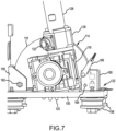
- Each of the assemblies 114 can be oriented in a locked position on the carriage or tilted to an unlocked position as shown in FIGS. 6 and 7 to permit installation of the carriages 122 or 124 on their respective rails 104 and 108.
- the spur gears 120 of the air motor drive assemblies 114 engage the closed slots in the ladder surface of the guide rail 104 , 108 . Furthermore, they are easily separated from the carriage 122 , 124 to which they are mounted simply by removal of two pins.
- FIG. 4 A separate perspective view of one of the air motor drive assemblies 114 is shown in FIG. 4 .
- An exploded view of the air motor drive assembly 114 is shown in FIG. 5 .
- the air motor drive assembly 114 includes an air motor 126 having a cylindrical shape driving a step shaft 128 to which is mounted a multipole magnet ring 130 .
- the step shaft 128 and multipole ring 130 fit through an annular position sensor housing 132 with the step shaft 128 extending into a worm gear reducer gearbox 116 .
- One exemplary gearbox 116 is a Montevario gearbox.
- the output shaft of the worm gear reducer gearbox 116 turns a spur gear shaft 134 that is keyed to the spur gear 120 .
- the spur gear 120 is housed within a D shaped hollow spur gear housing 118 fastened to the gearbox 116 .
- Preferably about a third of the spur gear teeth extend out through the straight open side of the D shaped housing 118 .
- a detector circuit board 133 is fastened to a bayonet connector 135 which is in turn fastened to the outer surface of the position sensor housing 132 .
- This detector circuit board 133 carries a hall effect sensor that picks up magnetic pole transitions of the multipole magnet ring 130 as the air motor 126 rotates the step shaft 128 and thereby rotates the multipole magnet ring.
- This circuit board 133 is preferably part of the bayonet connector 135 .
- a cable (not shown) is fastened to the bayonet connector 135 to transmit the sensed magnetic pole transitions to a processor for signal processing of the transitions into signals indicative of the precise position of the carriage 122 or 124 on the rail 104 or 108 respectively. These signals are in turn utilized to track flexible lance drive apparatus position with respect to the tube sheet 102 .
- This D shaped hollow spur gear housing 118 has an arcuate portion 136 and a straight portion 138 that join at corners 140 and 142.
- a generally D shaped cover plate 144 is fastened to the outer surface of the housing 118 to partially enclose the spur gear 120 therein.
- the D shaped housing 118 has a cross bore 146 therethrough adjacent corner 140 and another cross bore 148 therethrough adjacent corner 142 .
- This spur gear housing 118 hides the spur gear 120 from external contact by a user and shields the assembly 114 from entry of debris and detritus expelled from heat exchanger tubes during use.
- the positioner support rail carriage 122 has a rectangular base plate 150 .
- Four support rollers 156 are rotatably fastened to the bottom of the base plate 150 . These rollers 156 roll along the ribs of the upper rail 104 when the carriage 122 is mounted on the upper rail 104 as shown in FIG. 1 .
- the base plate 150 has a rectangular cutout 154 therethrough.
- a first U shaped support block 158 and a second U shaped support block 160 are fastened to the top of the base plate 150 so as to open toward each other over the rectangular cutout 154 .
- Support block 158 has a single cross bore receiving a retaining pin 162 that passes through both the block 158 and the corner bore 142 of the D shaped housing 118 .
- Support block 160 has a first cross bore 164 complementarily positioned to the retaining pin 162 .
- This cross bore 164 corresponds to the spur gear housing 118 being flush with the upper surface of the base plate 150 over the cutout 154 so as to hide the teeth of the spur gear 120 , as is shown in FIG. 2 .
- a removable pin 166 is shown in FIG. 2 locking the spur gear housing 118 and hence the air motor assembly 114 in a down position so as to engage the spur gear 120 with the rail 104 on which the carriage 122 rolls.
- the support block 160 has a second cross bore 168 therethrough spaced directly above the cross bore 164 .
- This cross bore 164 receives the pin 166 through the bore 148 of the housing 118 to maintain the air motor assembly 114 out of engagement with the rail 104 as is shown in FIG. 7 .
- the carriage 122 also has a support plate 152 fastened at a right angle to one end of the base plate 150 .
- This support plate 152 carries a positioner drive rail clamp 169 that securely holds one end of the lance positioner support rail 108 in a position such as is shown in FIG. 1 .
- This carriage 124 includes a base plate 170 to which, on one side, four guide rollers 176 are mounted for riding on and guiding the carriage 124 along support rail 108 . Also mounted to the same side of the base plate 170 are U shaped first and second support blocks 172 and 174 . These support blocks 172 and 174 open toward each other and receive the D shaped spur gear housing 118 therebetween so that the spur gear 120 extends into the ladder shaped slots in the support rail 108 .
- One of the support blocks 172 has a single cross bore carrying a pivot pin 173 that extends through the cross bore 146 in the corner 140 of the spur gear housing 118 . (See FIG. 4 ).
- This pin 173 provides a pivot for the air motor assembly 114 .
- the other U shaped support block 174 has a first through bore 175 receiving removable pin 177 to lock the air motor assembly 114 into engagement with the rail 108 in the position as shown in FIG. 3A and 3B .
- the air motor assembly 114 may be pivoted about pin 173 when removable pin 177 is withdrawn and repositioned in the second, upper cross bore 179 as is shown in FIG. 6 , permitting the carriage 124 to be rolled onto and along the rail 108 without engaging the teeth of spur gear 120 with the ladder slots in the rail 108 .
- This flexible lance drive device may be a one, two or three lance drive such as StoneAge's ProDrive, ABX2L or one of StoneAge's ABX3L drives.
- FIG. 8 is a separate perspective view of the lower guide rail follower roller carriage assembly 112 shown in FIG. 1 .
- This follower roller carriage assembly 112 has an inverted generally Y shaped base plate 190 carrying three rollers 156 , one on each leg of the Y shaped base plate 190 . These rollers 156 roll along the lower rail 106 and prevent outward movement of the assembly 112 away from the rail 106 .
- On the opposite side of the base plate 190 are a pair of guide rollers 192 fastened to an elongated support member 194 which is spaced from the base plate 190 by a spacer block 196 . These guide rollers 192 are spaced to capture the lower end portion of the support rail 108 therebetween.
- the guide rollers 192 prevent outward movement of the support rail 108 while at the same time permitting vertical movement of the support rail 108 between the rollers 192 to compensate for non-parallel alignment between the upper rail 104 and lower rail 106 .
- Fastened to the top of the inverted Y shaped base plate 190 is a cup shaped hollow scraper hood 198 arranged to cover the upper end of the base plate 190 and the upper roller 156 . Its lower edge 199 scrapes along the top of the rail 106 (See FIG. 1 ) carried between the three rollers 156 .
- This scraper hood 198 deflects debris expelled from the heat exchanger tubes while they are being cleaned and prevents the debris from accumulating on the rail 106 and interfering with the upper roller 156 fastened to the base plate 190 . This ensures that the assembly 112 remains free to roll along the rail 106 as the rail 108 is translated back and forth over the tube sheet 102 .
- the rotation position sensor 132 may be other than as specifically described above.
- the multipole magnetic ring 130 and the sensor 133 could alternatively be mounted to the shaft 134 of the spur gear 120 or incorporated into one of the roller assemblies 156 or 176 instead of directly mounted to the step shaft 128 of the air motor 126 as shown.
- the air motor assembly 114 may be configured to linearly slide into and out of the support blocks 172 , 174 and 158 and 160 rather than pivot as described above. Many other changes will become apparent to a reader given the disclosure above.
Landscapes
- Engineering & Computer Science (AREA)
- Chemical & Material Sciences (AREA)
- Combustion & Propulsion (AREA)
- Mechanical Engineering (AREA)
- General Engineering & Computer Science (AREA)
- Incineration Of Waste (AREA)
- Investigating Or Analyzing Materials By The Use Of Magnetic Means (AREA)
- Cleaning In General (AREA)
- Carbon Steel Or Casting Steel Manufacturing (AREA)
Description
- The present disclosure is directed to high pressure fluid rotary nozzle systems. In particular, embodiments of the present disclosure are directed to an apparatus for positioning one or more flexible tube cleaning lances in registry with a heat exchanger tube sheet.
- Conventional lance positioner frames are heavy rigid frame structures that can be assembled adjacent a heat exchanger once the tube sheet flange cover has been removed. Alternatively such frame assemblies can be bolted to the tube sheet directly.
US Patent Nos. 4095305 ,6626195 ,6681839 , and7530363 disclose exemplary rectilinear frames adapted to be positioned adjacent or fastened to a heat exchanger tube sheet. Such assemblies are heavy, generally awkward to set up and utilize, and most require a substantial amount of space adjacent to or in line with the tube sheet which may limit the feasibility of using such assemblies. An apparatus for precisely positioning one or more cleaning lances in registry with a heat exchanger tube sheet that is simple to erect, remains rigid, and takes up minimal space adjacent the tube sheet is disclosed in ourUS Patent Nos. 10,024,613 10,684,082
US 2016/0025432 discloses a flexible multi-tube cleaning lance positioner with a guide tube pitch adjustment apparatus.
WO2016/014626 andUS 2016/0025433 disclose a frame apparatus for holding a flexible lance apparatus and a positioning mechanism to position the lance in alignment with tubes in a plate for cleaning. - The invention is defined by the appended independent claims. A selection of optional features of the invention is set out in the dependent claims.
-
-
FIG. 1 is a perspective view of an exemplary embodiment of a flexible lance positioner frame apparatus in accordance with the present disclosure oriented against and fastened to an exemplary heat exchanger tube sheet. -
FIG. 2 is a separate perspective view of a positioner support rail carriage assembly in accordance with the present disclosure. -
FIG. 3A is a left perspective view of a lance drive carriage assembly shown inFIG. 1 . -
FIG. 3B is a right perspective view of the lance drive carriage assembly shown inFIG. 3A . -
FIG. 4 is a. separate perspective view of the air motor drive assembly in accordance with the present disclosure. -
FIG. 5 is an exploded view of the air motor drive assembly in accordance with the present disclosure. -
FIG. 6 is a side view of the lance positioner drive carriage shown inFIG. 3A with the air motor drive assembly in the unlocked position. -
FIG. 7 is a partial side view of the positioner support rail carriage showing the air motor drive assembly in the unlocked position. -
FIG. 8 is a separate perspective view of the lower guide rail follower roller carriage assembly in accordance with the present disclosure. - An
exemplary frame apparatus 100 in accordance with the present disclosure is shown inFIG. 1 , fastened to a heatexchanger tube sheet 102. Theapparatus 100 has an upper generallyhorizontal guide rail 104, alower guide rail 106, and a verticalpositioner support rail 108 that supports a flexible lancepositioner drive carriage 124. Theupper guide rail 104 serves to provide precise mechanical alignment with rows of tubes present in the heat exchanger bundle. Theupper guide rail 104 carries a positionersupport rail carriage 122 for back and forth movement along theupper guide rail 104. The positionersupport rail carriage 122 in turn supports thepositioner support rail 108 for movement of thepositioner support rail 108, inFIG. 1 , horizontally back and forth in a parallel plane over thetube sheet 102. - The
positioner support rail 108 carries a flexible lancepositioner drive carriage 124. When so aligned, thecarriage 124, separately shown inFIGS. 3A and 3B , can be moved up and down along thesupport rail 108 to position a flexible lance drive apparatus (not shown) at precise positions in line with selected tube penetrations through thetube sheet 102. Thelower guide rail 106 does not have to be installed precisely parallel to theupper guide rail 104 as the lower guide rail followerroller carriage assembly 112 can tolerate reasonable rotation within a plane roughly parallel to the face of thetube sheet 102. Thelower guide rail 106 and lower guide railfollower carriage assembly 112 serve to mechanically support thecarriage 124 in position and prevent deflection of thecarriage 124 away axially from thetube sheet 102 generated by jet thrust, machine mass or force imparted to the system by the interaction between the flexible lance drive assembly (not shown) fastened to thecarriage 124, the flexible lance(s) and the heat exchanger tubes. - Each of the upper and
lower guide rails tube sheet 102 via, for example, aclamp plate assembly 110 such as is shown in more detail in our patents10,024,613 10,684,082 - The positioner support
rail carriage 122, separately shown inFIG. 2 , is remotely operated to move thesupport rail 108 back and forth along theupper guide rail 104. It is to be understood that the above configuration may be reversed, with thedrive mechanism 122 mounted on thelower guide rail 106 and thefollower roller assembly 112 mounted on theupper guide rail 104. In such a case, the alignment of thelower guide rail 106 with respect to the tube penetrations through thetube sheet 102 would be critical. - Each of the
upper guide rail 104, thelower guide rail 106, and thepositioner support rail 108 shown inFIG. 1 is preferably an aluminum box rail extrusion having, in cross section, a generally rectangular tube shape having four side walls. Each of the four corners of the rail extrusion extends outward to form an axially extending external rib. Preferably at least one of the side walls of each guide rail has a series of spaced closed slots forming essentially a ladder surface that is designed to operably engage with aspur gear 120 driven by one of theair motors 126 in thecarriages rails carriages follower roller assembly 112. - Each of the
carriages motor drive assembly 114 in accordance with the present disclosure fastened thereto for engaging the closed slots in the ladder surface of the guide rail to which the carriage, 122 or 124, is attached. The airmotor drive assemblies 114 are each interchangeable betweencarriages assemblies 114 can be oriented in a locked position on the carriage or tilted to an unlocked position as shown inFIGS. 6 and7 to permit installation of thecarriages respective rails spur gears 120 of the airmotor drive assemblies 114 engage the closed slots in the ladder surface of theguide rail carriage - A separate perspective view of one of the air
motor drive assemblies 114 is shown inFIG. 4 . An exploded view of the airmotor drive assembly 114 is shown inFIG. 5 . The airmotor drive assembly 114 includes anair motor 126 having a cylindrical shape driving astep shaft 128 to which is mounted amultipole magnet ring 130. Thestep shaft 128 andmultipole ring 130 fit through an annularposition sensor housing 132 with thestep shaft 128 extending into a wormgear reducer gearbox 116. Oneexemplary gearbox 116 is a Montevario gearbox. The output shaft of the wormgear reducer gearbox 116 turns aspur gear shaft 134 that is keyed to thespur gear 120. Thespur gear 120 is housed within a D shaped hollowspur gear housing 118 fastened to thegearbox 116. Preferably about a third of the spur gear teeth extend out through the straight open side of the D shapedhousing 118. - A
detector circuit board 133 is fastened to abayonet connector 135 which is in turn fastened to the outer surface of theposition sensor housing 132. One embodiment of thisdetector circuit board 133 carries a hall effect sensor that picks up magnetic pole transitions of themultipole magnet ring 130 as theair motor 126 rotates thestep shaft 128 and thereby rotates the multipole magnet ring. Thiscircuit board 133 is preferably part of thebayonet connector 135. A cable (not shown) is fastened to thebayonet connector 135 to transmit the sensed magnetic pole transitions to a processor for signal processing of the transitions into signals indicative of the precise position of thecarriage rail tube sheet 102. - This D shaped hollow
spur gear housing 118 has anarcuate portion 136 and astraight portion 138 that join atcorners cover plate 144 is fastened to the outer surface of thehousing 118 to partially enclose thespur gear 120 therein. The D shapedhousing 118 has across bore 146 therethroughadjacent corner 140 and anothercross bore 148 therethroughadjacent corner 142. Thisspur gear housing 118 hides thespur gear 120 from external contact by a user and shields theassembly 114 from entry of debris and detritus expelled from heat exchanger tubes during use. - Referring now to
FIG. 2 , a separate perspective view of the positionersupport rail carriage 122 is shown. The positionersupport rail carriage 122 has arectangular base plate 150. Foursupport rollers 156 are rotatably fastened to the bottom of thebase plate 150. Theserollers 156 roll along the ribs of theupper rail 104 when thecarriage 122 is mounted on theupper rail 104 as shown inFIG. 1 . Thebase plate 150 has arectangular cutout 154 therethrough. A first U shapedsupport block 158 and a second U shapedsupport block 160 are fastened to the top of thebase plate 150 so as to open toward each other over therectangular cutout 154. -
Support block 158 has a single cross bore receiving a retainingpin 162 that passes through both theblock 158 and the corner bore 142 of the D shapedhousing 118.Support block 160 has afirst cross bore 164 complementarily positioned to the retainingpin 162. This cross bore 164 corresponds to thespur gear housing 118 being flush with the upper surface of thebase plate 150 over thecutout 154 so as to hide the teeth of thespur gear 120, as is shown inFIG. 2 . Aremovable pin 166 is shown inFIG. 2 locking thespur gear housing 118 and hence theair motor assembly 114 in a down position so as to engage thespur gear 120 with therail 104 on which thecarriage 122 rolls. Thesupport block 160 has asecond cross bore 168 therethrough spaced directly above thecross bore 164. This cross bore 164 receives thepin 166 through thebore 148 of thehousing 118 to maintain theair motor assembly 114 out of engagement with therail 104 as is shown inFIG. 7 . Turning back toFIG. 2 , thecarriage 122 also has asupport plate 152 fastened at a right angle to one end of thebase plate 150. Thissupport plate 152 carries a positionerdrive rail clamp 169 that securely holds one end of the lancepositioner support rail 108 in a position such as is shown inFIG. 1 . - .Turning now to
FIGS. 3A and 3B , left and right views of the flexiblelance positioner carriage 124 are shown. Thiscarriage 124 includes abase plate 170 to which, on one side, fourguide rollers 176 are mounted for riding on and guiding thecarriage 124 alongsupport rail 108. Also mounted to the same side of thebase plate 170 are U shaped first and second support blocks 172 and 174. These support blocks 172 and 174 open toward each other and receive the D shapedspur gear housing 118 therebetween so that thespur gear 120 extends into the ladder shaped slots in thesupport rail 108. One of the support blocks 172 has a single cross bore carrying apivot pin 173 that extends through thecross bore 146 in thecorner 140 of thespur gear housing 118. (SeeFIG. 4 ). Thispin 173 provides a pivot for theair motor assembly 114. The other U shapedsupport block 174 has a first throughbore 175 receivingremovable pin 177 to lock theair motor assembly 114 into engagement with therail 108 in the position as shown inFIG. 3A and 3B . As with thecarriage 122, theair motor assembly 114 may be pivoted aboutpin 173 whenremovable pin 177 is withdrawn and repositioned in the second,upper cross bore 179 as is shown inFIG. 6 , permitting thecarriage 124 to be rolled onto and along therail 108 without engaging the teeth ofspur gear 120 with the ladder slots in therail 108. - Fastened to the other side of the
base 170 ofcarriage 124 is a fixedclamp 180 andmovable clamp 178 for removably capturing and clamping the flexible lance drive device (not shown) to thecarriage 124. This flexible lance drive device may be a one, two or three lance drive such as StoneAge's ProDrive, ABX2L or one of StoneAge's ABX3L drives. -
FIG. 8 is a separate perspective view of the lower guide rail followerroller carriage assembly 112 shown inFIG. 1 . This followerroller carriage assembly 112 has an inverted generally Y shapedbase plate 190 carrying threerollers 156, one on each leg of the Y shapedbase plate 190. Theserollers 156 roll along thelower rail 106 and prevent outward movement of theassembly 112 away from therail 106. On the opposite side of thebase plate 190 are a pair ofguide rollers 192 fastened to anelongated support member 194 which is spaced from thebase plate 190 by aspacer block 196. These guiderollers 192 are spaced to capture the lower end portion of thesupport rail 108 therebetween. Theguide rollers 192 prevent outward movement of thesupport rail 108 while at the same time permitting vertical movement of thesupport rail 108 between therollers 192 to compensate for non-parallel alignment between theupper rail 104 andlower rail 106. Fastened to the top of the inverted Y shapedbase plate 190 is a cup shapedhollow scraper hood 198 arranged to cover the upper end of thebase plate 190 and theupper roller 156. Itslower edge 199 scrapes along the top of the rail 106 (SeeFIG. 1 ) carried between the threerollers 156. Thisscraper hood 198 deflects debris expelled from the heat exchanger tubes while they are being cleaned and prevents the debris from accumulating on therail 106 and interfering with theupper roller 156 fastened to thebase plate 190. This ensures that theassembly 112 remains free to roll along therail 106 as therail 108 is translated back and forth over thetube sheet 102. - Many changes may be made to the apparatus described above, which will become apparent to a reader of this disclosure. For example, the
rotation position sensor 132 may be other than as specifically described above. The multipolemagnetic ring 130 and thesensor 133 could alternatively be mounted to theshaft 134 of thespur gear 120 or incorporated into one of theroller assemblies step shaft 128 of theair motor 126 as shown. Alternatively, theair motor assembly 114 may be configured to linearly slide into and out of the support blocks 172, 174 and 158 and 160 rather than pivot as described above. Many other changes will become apparent to a reader given the disclosure above. - All such changes, alternatives and equivalents in accordance with the features of the appended claims, are within the scope of the present disclosure.
Claims (7)
- A frame apparatus for holding a flexible lance drive device adjacent to and spaced from a heat exchanger tube sheet, the apparatus comprising:an upper guide rail (104);a lower guide rail (106);a positioner support rail (108) supported from one of the upper and lower guide rails (104, 106) and guided by the other of the upper and lower guide rails (104, 106); anda positioner support rail carriage (122) movably mounted on the one of the upper and lower guide rails (104, 106);a flexible lance drive support carriage (124) movably mounted on the positioner support rail; and characterized byan air motor drive assembly (114) fastened to each of the positioner support rail carriage (122) and the lance drive support carriage (124), each air motor drive assembly (114) comprising an air motor (126) having a shaft carrying a rotational position sensor thereon and driving a spur gear (120) through a worm gear reducer (116), wherein the spur gear (120) is carried within a spur gear housing (118) fastened to the worm gear reducer (116), and wherein the air motor assembly (114) is fastened to the carriage (122) via the spur gear housing (118) and the spur gear housing (118) is selectively rotatable on the carriage (122, 124) between a locked position with the spur gear (120) engaging the rail to which the carriage (122, 124) is mounted and an unlocked position with the spur gear (120) disengaged with the rail to which the carriage (122, 124) is mounted.
- The apparatus according to claim 1 wherein the rotational position sensor includes a multipole magnetic ring (130) mounted on a step shaft (128) rotated by the air motor (126), wherein optionally the rotational position sensor is supported in a sensor housing (132) between the air motor (126) and the worm gear reducer (116), and optionally the rotational position sensor further includes a hall effect detector fastened to the sensor housing (132).
- An air motor drive assembly for use on a lance positioner frame apparatus having an upper guide rail (104) supporting a positioner support rail carriage (122) and a lance positioner drive rail (108) carrying a lance drive support carriage (124), the air motor drive assembly (114) being characterized by an air motor (126) having a shaft driving a spur gear (120) through a worm gear reducer (116), wherein the spur gear (120) is carried within a spur gear housing (118) fastened to the worm gear reducer (116), and wherein spur gear housing (118) is selectively rotatable on either one of the carriages (122, 124) between a locked position with the spur gear (120) engaging the rail (104, 108) to which the one of the carriages (122, 124) is mounted and an unlocked position with the spur gear (120) is disengaged with the rail (104, 108) to which the one of the carriages (122, 124) is mounted.
- The assembly according to claim 3 further comprising each of the carriages (122, 124) having a first U shaped block (158) fastened thereto and a second U shaped block (160) fastened thereto each receiving a corner portion of the spur gear housing (118) therein.
- The assembly according to claim 4 wherein each one of the first and second U shaped blocks (158. 160) has a first cross bore therethrough carrying a pin through the corner portion of the spur gear housing (118) therein.
- The assembly according to claim 5 wherein one of the first and second U shaped blocks (158, 160) has a second cross bore therethrough spaced above the first cross bore and the pin through the first cross bore is removable to permit the spur gear housing (118) to be rotated about the other U shaped block (158, 160) until the removable pin can be inserted through the second cross bore thereby lifting the spur gear (120) out of engagement with the rail to which the carriage is mounted.
- The apparatus according to any of claims 3 to 6 further comprising a rotational sensor housing fastened between the air motor (126) and the worm gear reducer (116) and the air motor (126) having a step shaft (128) carrying a multipole magnetic ring (130) within the sensor housing , and a hall effect detector fastened to the sensor housing (132), the apparatus optionally further comprising a connector fastened to the hall effect detector, wherein optionally the multipole magnetic ring (130) carries 24 poles providing 24 pole reversal transitions.
Priority Applications (1)
| Application Number | Priority Date | Filing Date | Title |
|---|---|---|---|
| EP24164561.3A EP4382851A3 (en) | 2020-08-18 | 2021-06-25 | Flexible tube cleaning lance positioner frame apparatus |
Applications Claiming Priority (2)
| Application Number | Priority Date | Filing Date | Title |
|---|---|---|---|
| US16/996,689 US11713932B2 (en) | 2020-08-18 | 2020-08-18 | Flexible tube cleaning lance positioner frame apparatus |
| EP21181855.4A EP3957944B2 (en) | 2020-08-18 | 2021-06-25 | Flexible tube cleaning lance positioner frame apparatus |
Related Parent Applications (2)
| Application Number | Title | Priority Date | Filing Date |
|---|---|---|---|
| EP21181855.4A Division EP3957944B2 (en) | 2020-08-18 | 2021-06-25 | Flexible tube cleaning lance positioner frame apparatus |
| EP21181855.4A Division-Into EP3957944B2 (en) | 2020-08-18 | 2021-06-25 | Flexible tube cleaning lance positioner frame apparatus |
Related Child Applications (1)
| Application Number | Title | Priority Date | Filing Date |
|---|---|---|---|
| EP24164561.3A Division EP4382851A3 (en) | 2020-08-18 | 2021-06-25 | Flexible tube cleaning lance positioner frame apparatus |
Publications (2)
| Publication Number | Publication Date |
|---|---|
| EP4187192A1 EP4187192A1 (en) | 2023-05-31 |
| EP4187192B1 true EP4187192B1 (en) | 2024-03-20 |
Family
ID=76695495
Family Applications (3)
| Application Number | Title | Priority Date | Filing Date |
|---|---|---|---|
| EP24164561.3A Pending EP4382851A3 (en) | 2020-08-18 | 2021-06-25 | Flexible tube cleaning lance positioner frame apparatus |
| EP22216434.5A Active EP4187192B1 (en) | 2020-08-18 | 2021-06-25 | Flexible tube cleaning lance positioner frame apparatus |
| EP21181855.4A Active EP3957944B2 (en) | 2020-08-18 | 2021-06-25 | Flexible tube cleaning lance positioner frame apparatus |
Family Applications Before (1)
| Application Number | Title | Priority Date | Filing Date |
|---|---|---|---|
| EP24164561.3A Pending EP4382851A3 (en) | 2020-08-18 | 2021-06-25 | Flexible tube cleaning lance positioner frame apparatus |
Family Applications After (1)
| Application Number | Title | Priority Date | Filing Date |
|---|---|---|---|
| EP21181855.4A Active EP3957944B2 (en) | 2020-08-18 | 2021-06-25 | Flexible tube cleaning lance positioner frame apparatus |
Country Status (3)
| Country | Link |
|---|---|
| US (3) | US11713932B2 (en) |
| EP (3) | EP4382851A3 (en) |
| CA (1) | CA3123671A1 (en) |
Families Citing this family (4)
| Publication number | Priority date | Publication date | Assignee | Title |
|---|---|---|---|---|
| US11713932B2 (en) * | 2020-08-18 | 2023-08-01 | Stoneage, Inc. | Flexible tube cleaning lance positioner frame apparatus |
| EP4269927A1 (en) * | 2022-04-28 | 2023-11-01 | 3con Anlagebau GmbH | Cooling register for cold air generation |
| KR102608456B1 (en) * | 2023-07-27 | 2023-12-01 | 고려공업검사 주식회사 | Conveying device of tubular water and foreign matter removal device in the heat exchanger tube for ECT inspection |
| US12485456B2 (en) * | 2024-05-09 | 2025-12-02 | Stoneage, Inc. | Arc turntable cleaner |
Citations (5)
| Publication number | Priority date | Publication date | Assignee | Title |
|---|---|---|---|---|
| US4095305A (en) | 1975-10-31 | 1978-06-20 | C. H. Heist Corporation | Cleaning apparatus for tubes and tube bundles |
| US6681839B1 (en) | 2001-02-23 | 2004-01-27 | Brent A. Balzer | Heat exchanger exchange-tube cleaning lance positioning system |
| WO2006101674A1 (en) | 2005-03-21 | 2006-09-28 | Hr Textron, Inc. | Position sensing for moveable mechanical systems and associated methods and apparatus |
| US20060249185A1 (en) | 2001-03-16 | 2006-11-09 | Garman Daniel T | High pressure tube cleaning apparatus |
| WO2020086873A1 (en) | 2018-10-26 | 2020-04-30 | Stoneage, Inc. | Auto-indexing lance positioner apparatus and system |
Family Cites Families (73)
| Publication number | Priority date | Publication date | Assignee | Title |
|---|---|---|---|---|
| US1486481A (en) | 1921-11-10 | 1924-03-11 | Canedy Otto Mfg Co | Motor stand |
| GB230076A (en) | 1924-02-27 | 1926-02-04 | Bendix Brake Co | Improvements in ball and socket joints |
| US3354490A (en) | 1964-06-15 | 1967-11-28 | Power Tube Inc | Boiler tube cleaning apparatus |
| US3459354A (en) | 1966-03-08 | 1969-08-05 | Halliburton Co | Wheel mounting structure |
| US3938535A (en) | 1972-08-07 | 1976-02-17 | Browning-Ferris Industries, Inc. | Tube cleaning device |
| US3836015A (en) * | 1973-03-29 | 1974-09-17 | B Travis | Tube bundle extractor |
| GB1516307A (en) * | 1974-09-09 | 1978-07-05 | Babcock & Wilcox Ltd | Apparatus for conveying a device for inspecting or performing operations on the interior of a tube |
| US4043375A (en) | 1975-10-28 | 1977-08-23 | Caterpillar Tractor Co. | Rim construction and tool apparatus for safe tire inflation |
| US4102527A (en) | 1977-06-09 | 1978-07-25 | Alexander Dewey D | Gripping pry tools for dislodging concrete forms and the like |
| DE2825228A1 (en) | 1978-06-08 | 1979-12-13 | Myers Europ Gmbh | FEED DRIVE FOR A TUBE SNAKE |
| US4177539A (en) * | 1978-09-26 | 1979-12-11 | Elting Larry M | Oscillating soot blower mechanism |
| NL174118C (en) | 1978-12-04 | 1986-11-17 | Homburg Machinehandel | DEVICE FOR CLEANING WATER TUBES. |
| US4235362A (en) | 1979-03-21 | 1980-11-25 | Pfizer Inc. | Wire-feeding apparatus |
| US4381105A (en) | 1980-05-08 | 1983-04-26 | Gordon W. Hueschen | Clamp |
| US4404838A (en) | 1981-07-23 | 1983-09-20 | Hare Charles E | System for straightening bent automobile bodies |
| DE8135474U1 (en) | 1981-12-05 | 1982-04-15 | Veltrup, Elmar Michael, Dipl.-Ing., 4150 Krefeld | DEVICE FOR CLEANING TUBES |
| US4538796A (en) | 1982-07-26 | 1985-09-03 | Steck Manufacturing Co., Inc. | Dolly |
| US4445668A (en) | 1982-07-26 | 1984-05-01 | Sauber Charles J | Cable feeding system |
| AU569780B2 (en) | 1984-03-15 | 1988-02-18 | Alfred Leslie Gilmore | Improvements to bore hole pump sets |
| GB2179637A (en) | 1985-08-29 | 1987-03-11 | Jetin Ind Ltd | Cleaning/treating internal cavities |
| DE8712637U1 (en) | 1987-09-18 | 1989-01-12 | Siemens AG, 1000 Berlin und 8000 München | Cleaning device for heat exchangers with tube bundles, especially for the tube sheet and spacer plate area |
| US4944465A (en) | 1989-05-11 | 1990-07-31 | Levine Aaron J | Spring driving and winding machine |
| US5002120A (en) | 1990-03-08 | 1991-03-26 | Boisture Thomas B | Multi-lance tube cleaning system |
| US5022463A (en) | 1990-03-08 | 1991-06-11 | Ohmstede Mechanical Services, Inc. | Multi-hose flexible lance tube cleaning system |
| US5423917A (en) | 1993-02-12 | 1995-06-13 | Garcia, Jr.; Ralph | Method for cleaning heat exchanger tubes by creating shock wave and mixing the liquid with injected air |
| US5320072A (en) | 1993-06-07 | 1994-06-14 | B&W Nuclear Service Company | Apparatus for removing sludge deposits |
| WO1996017695A1 (en) | 1994-12-07 | 1996-06-13 | Foster-Miller, Inc. | Deployment system for an upper bundle steam generator cleaning/inspection device |
| JP3599745B2 (en) | 1995-03-15 | 2004-12-08 | フラマトム アンプ ゲゼルシャフト ミット ベシュレンクテル ハフツング | Flexible lance for processing or inspection of steam generator tube floor |
| FR2742858B1 (en) | 1995-12-22 | 1998-03-06 | Framatome Sa | METHOD AND DEVICE FOR CLEANING A TUBULAR PLATE OF A HEAT EXCHANGER FROM THE INSIDE OF THE HEAT EXCHANGER BEAM |
| DE29612512U1 (en) | 1996-07-19 | 1996-11-28 | Kapchinus, Birgit, 37290 Meißner | Device for cleaning sewage pipes with a hollow wound cleaning spiral |
| US5915742A (en) | 1997-10-14 | 1999-06-29 | Hung; Wen-Cheng | Car door separating and attaching device |
| DE19819406C2 (en) | 1998-04-30 | 2000-05-31 | Wolfgang Rausch Gmbh & Co Kg E | Device for rinsing channels, in particular house connection channels |
| FI20010162A0 (en) | 2001-01-26 | 2001-01-26 | Timo Juhani Vanhatalo | Method and apparatus for cleaning pipes in a heat exchanger |
| AUPR335201A0 (en) | 2001-02-26 | 2001-03-22 | Enter Global Ltd | Apparatus for cleaning a conduit interior and method therefor |
| US6626195B1 (en) | 2001-03-16 | 2003-09-30 | Aqua Dynamics, Inc. | High pressure tube cleaning apparatus |
| US6557742B1 (en) | 2001-04-18 | 2003-05-06 | Lincoln Global, Inc. | Drive roller for wire feeding mechanism |
| US6910360B2 (en) | 2001-10-23 | 2005-06-28 | L&P Property Management Company | Multiple wire feed for spring coiling machine and method |
| US7303386B1 (en) | 2002-08-30 | 2007-12-04 | Brown Machine Llc | Method and apparatus for squaring and flattening sheets |
| EP1651362A4 (en) | 2003-07-03 | 2011-07-20 | Chief R Davis | Apparatus and method for inspecting sewer lines using small mobile vehicles |
| US7448606B1 (en) | 2003-12-04 | 2008-11-11 | Innovative Tools & Technologies, Inc. | Large automotive panel paint rack |
| DE10357021A1 (en) | 2003-12-05 | 2005-07-07 | Clyde Bergemann Gmbh | Compact sootblower |
| WO2006021164A1 (en) | 2004-08-20 | 2006-03-02 | A. Monforts Textilmaschinen Gmbh & Co. Kg | Tubular heat exchanger |
| US20070022950A1 (en) | 2005-07-18 | 2007-02-01 | Livingston William A | Autocycle universal stand |
| US7798479B1 (en) | 2005-12-01 | 2010-09-21 | The United States Of America As Represented By The Secretary Of The Navy | Method and apparatus for horizontal assembly of a high-voltage feed-through bushing |
| KR101106203B1 (en) | 2006-02-22 | 2012-01-20 | 가부시키가이샤 에바라 세이사꾸쇼 | Substrate processing apparatus |
| KR100829264B1 (en) | 2006-08-14 | 2008-05-13 | 한전케이피에스 주식회사 | Tube support plate and heat pipe cleaning system of Westinghouse F-type steam generator |
| FR2904940B1 (en) | 2006-08-21 | 2010-05-21 | Applic Lorraine Des Tech Nouve | METHOD OF TUBING ACTION BY TAKING A VERY HIGH PRESSURE FLUID |
| EP2034266A3 (en) * | 2007-09-10 | 2013-07-24 | JNW CleaningSolutions GmbH | Heat exchange device with angled or perpendicular surfaces and with cleaning |
| US20090211612A1 (en) | 2008-01-08 | 2009-08-27 | Christos Athanassiu | Super-thin water jetting lance |
| US7877889B2 (en) | 2008-03-05 | 2011-02-01 | Griffin Jr Jack C | Anchor bolt positioning system |
| CA2718951A1 (en) | 2008-03-20 | 2009-09-24 | Aquilex Hydrochem, Inc. | Automated heat exchanger tube cleaning assembly and system |
| KR101086344B1 (en) * | 2009-07-01 | 2011-11-23 | 한전케이피에스 주식회사 | Visual inspection and debris removal device for bundle gap of heat pipe in the upper part of steam generator secondary tube |
| WO2011047258A1 (en) | 2009-10-15 | 2011-04-21 | Aquilex Hydrochem, Inc. | Driving apparatus for one or more cleaning lances |
| WO2012037560A2 (en) * | 2010-09-17 | 2012-03-22 | Aquilex Hydrochem, Inc. | Semi-automated heat exchanger tube cleaning assembly and method |
| CN102135391B (en) * | 2011-02-02 | 2012-11-28 | 柳州市汉森机械制造有限公司 | Machine and method for cleaning evaporation tank |
| CN102305574B (en) * | 2011-08-23 | 2013-10-02 | 柳州市汉森机械制造有限公司 | Cleaning machine for heat exchange pipe of evaporator |
| JP6077886B2 (en) | 2013-03-04 | 2017-02-08 | 株式会社荏原製作所 | Plating equipment |
| US10408552B2 (en) * | 2013-05-09 | 2019-09-10 | Terydon, Inc. | Indexer, indexer retrofit kit and method of use thereof |
| US10780628B2 (en) * | 2014-07-18 | 2020-09-22 | Fusion3 Design LLC | Apparatus and method for fabricating three-dimensional objects |
| US10024613B2 (en) * | 2014-07-24 | 2018-07-17 | Stoneage, Inc. | Flexible tube cleaning lance positioner frame apparatus |
| EP3172519B1 (en) | 2014-07-24 | 2018-07-18 | Stoneage, Inc. | Flexible tube cleaning lance positioner frame apparatus |
| US9400145B2 (en) * | 2014-07-25 | 2016-07-26 | Stoneage, Inc. | Flexible multi-tube cleaning lance positioner guide apparatus |
| CA3216869A1 (en) * | 2014-10-06 | 2016-04-14 | Stoneage, Inc. | Flexible cleaning lance positioner guide apparatus |
| CN107107090B (en) * | 2015-01-09 | 2019-08-16 | 石器时代股份公司 | High pressure water spray nozzle manipulator device |
| US20160243597A1 (en) * | 2015-02-24 | 2016-08-25 | PSI Pressure Systems Corp. | Magnetic mount for blasting equipment and related methods |
| US11460258B2 (en) * | 2015-10-16 | 2022-10-04 | Peinemann Equipment B.V. | System for cleaning an object such as a heat exchanger |
| US10809023B2 (en) * | 2017-03-20 | 2020-10-20 | Stoneage, Inc. | Flexible tube cleaning lance positioner apparatus |
| WO2020172059A1 (en) * | 2019-02-20 | 2020-08-27 | Stoneage, Inc. | Flexible lance drive positioner apparatus |
| KR20200125036A (en) * | 2019-04-25 | 2020-11-04 | 비씨태창산업(유) | Waste water reprocessing based heat exchanger bundle automatic cleaning device |
| EP4024000B1 (en) * | 2019-11-01 | 2024-09-18 | BC Taechan Industrial Corp. | Apparatus for automatically cleaning heat exchanger bundle |
| KR102190488B1 (en) * | 2019-11-01 | 2020-12-11 | 비씨태창산업(유) | Heat exchanger bundle automatic cleaning device |
| US11674761B2 (en) * | 2020-01-08 | 2023-06-13 | Terydon, Inc. | Lance cleaning system with movable support |
| US11713932B2 (en) * | 2020-08-18 | 2023-08-01 | Stoneage, Inc. | Flexible tube cleaning lance positioner frame apparatus |
-
2020
- 2020-08-18 US US16/996,689 patent/US11713932B2/en active Active
-
2021
- 2021-06-25 EP EP24164561.3A patent/EP4382851A3/en active Pending
- 2021-06-25 EP EP22216434.5A patent/EP4187192B1/en active Active
- 2021-06-25 EP EP21181855.4A patent/EP3957944B2/en active Active
- 2021-06-30 CA CA3123671A patent/CA3123671A1/en active Pending
-
2023
- 2023-07-31 US US18/228,279 patent/US12345483B2/en active Active
-
2025
- 2025-06-30 US US19/254,969 patent/US20260043626A1/en active Pending
Patent Citations (5)
| Publication number | Priority date | Publication date | Assignee | Title |
|---|---|---|---|---|
| US4095305A (en) | 1975-10-31 | 1978-06-20 | C. H. Heist Corporation | Cleaning apparatus for tubes and tube bundles |
| US6681839B1 (en) | 2001-02-23 | 2004-01-27 | Brent A. Balzer | Heat exchanger exchange-tube cleaning lance positioning system |
| US20060249185A1 (en) | 2001-03-16 | 2006-11-09 | Garman Daniel T | High pressure tube cleaning apparatus |
| WO2006101674A1 (en) | 2005-03-21 | 2006-09-28 | Hr Textron, Inc. | Position sensing for moveable mechanical systems and associated methods and apparatus |
| WO2020086873A1 (en) | 2018-10-26 | 2020-04-30 | Stoneage, Inc. | Auto-indexing lance positioner apparatus and system |
Non-Patent Citations (3)
| Title |
|---|
| ANONYMOUS: "MAINTENANCE AND OPERATING INSTRUCTIONS FOR WORM GEAR REDUCERS AND GEARMOTORS SERIES: NMRV - MCV - NRV NMRV+NMRV PC+NMRV", MOTOVARIO, 15 July 1999 (1999-07-15), XP093189840 |
| ANONYMOUS: "Rotary encoder", WIKIPEDIA, 25 July 2020 (2020-07-25), XP093189837, Retrieved from the Internet <URL:https://en.wikipedia.org/w/index.php?title=Rotary_encoder&oldid=969428024> |
| ANONYMOUS: "User Manual Air Preheater Cleaner automatic cleaning of air preheaters Version 1", MANUAL APC, 12 June 2018 (2018-06-12), pages 1 - 101, XP093134726 |
Also Published As
| Publication number | Publication date |
|---|---|
| EP3957944B1 (en) | 2022-12-28 |
| US20240027149A1 (en) | 2024-01-25 |
| US20260043626A1 (en) | 2026-02-12 |
| EP4382851A3 (en) | 2024-08-21 |
| US11713932B2 (en) | 2023-08-01 |
| US20220057151A1 (en) | 2022-02-24 |
| EP4187192A1 (en) | 2023-05-31 |
| US12345483B2 (en) | 2025-07-01 |
| EP3957944B2 (en) | 2025-09-03 |
| EP4382851A2 (en) | 2024-06-12 |
| EP3957944A1 (en) | 2022-02-23 |
| CA3123671A1 (en) | 2022-02-18 |
Similar Documents
| Publication | Publication Date | Title |
|---|---|---|
| EP4187192B1 (en) | Flexible tube cleaning lance positioner frame apparatus | |
| US5572957A (en) | Automated sludge lance | |
| CA3042555C (en) | Apparatus for remotely propelling a flexible lance into and out of a piping system | |
| US20110000643A1 (en) | Apparatus for visually inspecting and removing foreign object in gaps of bundle of heating tubes of upper portion of tube sheet of secondary side of steam generator | |
| US9819842B2 (en) | Remote inspection apparatus for heating tube of steam generator | |
| CA3126461C (en) | Flexible lance drive positioner apparatus | |
| US5782209A (en) | Segmented automated sludge lance | |
| EP0004853B1 (en) | Improved apparatus for remotely repairing tubes in a steam generator | |
| US7152254B2 (en) | Mounting apparatus for pool cover assembly | |
| CN219074022U (en) | Automatic veneer reeling machine | |
| JP4448761B2 (en) | Submerged work device | |
| CN219032343U (en) | Drawing type rotating mechanism and coating device | |
| CN218520407U (en) | Electromechanical transmission device | |
| CN212419943U (en) | Portable welding seam strickles device off | |
| KR200180584Y1 (en) | Three-dimensional photographing system | |
| CN220207423U (en) | Bridge bottom surface crack detection device | |
| CN223517165U (en) | Charging pile and automatic dust removing device | |
| CN212135457U (en) | Face recognition device for smart city | |
| CA2158829C (en) | Segmented automated sludge lance | |
| CN220574791U (en) | Positioning device for processing pin rail of scraper conveyor | |
| CN220957548U (en) | Patrol monitoring equipment for workshop safety production | |
| CN221521613U (en) | Take-up device for pipeline detection | |
| CN221539919U (en) | Cutting device is used in processing of clean template | |
| CN211425932U (en) | Concrete core pulling device for house detection | |
| CN215462704U (en) | Filter element dust removal box device of natural gas horizontal filter |
Legal Events
| Date | Code | Title | Description |
|---|---|---|---|
| PUAI | Public reference made under article 153(3) epc to a published international application that has entered the european phase |
Free format text: ORIGINAL CODE: 0009012 |
|
| STAA | Information on the status of an ep patent application or granted ep patent |
Free format text: STATUS: THE APPLICATION HAS BEEN PUBLISHED |
|
| AC | Divisional application: reference to earlier application |
Ref document number: 3957944 Country of ref document: EP Kind code of ref document: P |
|
| AK | Designated contracting states |
Kind code of ref document: A1 Designated state(s): AL AT BE BG CH CY CZ DE DK EE ES FI FR GB GR HR HU IE IS IT LI LT LU LV MC MK MT NL NO PL PT RO RS SE SI SK SM TR |
|
| P01 | Opt-out of the competence of the unified patent court (upc) registered |
Effective date: 20230801 |
|
| STAA | Information on the status of an ep patent application or granted ep patent |
Free format text: STATUS: REQUEST FOR EXAMINATION WAS MADE |
|
| 17P | Request for examination filed |
Effective date: 20230905 |
|
| RBV | Designated contracting states (corrected) |
Designated state(s): AL AT BE BG CH CY CZ DE DK EE ES FI FR GB GR HR HU IE IS IT LI LT LU LV MC MK MT NL NO PL PT RO RS SE SI SK SM TR |
|
| GRAP | Despatch of communication of intention to grant a patent |
Free format text: ORIGINAL CODE: EPIDOSNIGR1 |
|
| STAA | Information on the status of an ep patent application or granted ep patent |
Free format text: STATUS: GRANT OF PATENT IS INTENDED |
|
| RIC1 | Information provided on ipc code assigned before grant |
Ipc: F28G 15/04 20060101ALI20230929BHEP Ipc: F28G 15/02 20060101ALI20230929BHEP Ipc: F28G 1/16 20060101AFI20230929BHEP |
|
| INTG | Intention to grant announced |
Effective date: 20231017 |
|
| GRAS | Grant fee paid |
Free format text: ORIGINAL CODE: EPIDOSNIGR3 |
|
| GRAA | (expected) grant |
Free format text: ORIGINAL CODE: 0009210 |
|
| STAA | Information on the status of an ep patent application or granted ep patent |
Free format text: STATUS: THE PATENT HAS BEEN GRANTED |
|
| AC | Divisional application: reference to earlier application |
Ref document number: 3957944 Country of ref document: EP Kind code of ref document: P |
|
| AK | Designated contracting states |
Kind code of ref document: B1 Designated state(s): AL AT BE BG CH CY CZ DE DK EE ES FI FR GB GR HR HU IE IS IT LI LT LU LV MC MK MT NL NO PL PT RO RS SE SI SK SM TR |
|
| REG | Reference to a national code |
Ref country code: GB Ref legal event code: FG4D |
|
| REG | Reference to a national code |
Ref country code: CH Ref legal event code: EP |
|
| REG | Reference to a national code |
Ref country code: IE Ref legal event code: FG4D |
|
| REG | Reference to a national code |
Ref country code: DE Ref legal event code: R096 Ref document number: 602021010768 Country of ref document: DE |
|
| REG | Reference to a national code |
Ref country code: DE Ref legal event code: R026 Ref document number: 602021010768 Country of ref document: DE |
|
| PLBI | Opposition filed |
Free format text: ORIGINAL CODE: 0009260 |
|
| PLAB | Opposition data, opponent's data or that of the opponent's representative modified |
Free format text: ORIGINAL CODE: 0009299OPPO |
|
| 26 | Opposition filed |
Opponent name: PEINEMANN EQUIPMENT B.V. Effective date: 20240502 |
|
| R26 | Opposition filed (corrected) |
Opponent name: PEINEMANN EQUIPMENT B.V. Effective date: 20240502 |
|
| PG25 | Lapsed in a contracting state [announced via postgrant information from national office to epo] |
Ref country code: LT Free format text: LAPSE BECAUSE OF FAILURE TO SUBMIT A TRANSLATION OF THE DESCRIPTION OR TO PAY THE FEE WITHIN THE PRESCRIBED TIME-LIMIT Effective date: 20240320 |
|
| REG | Reference to a national code |
Ref country code: LT Ref legal event code: MG9D |
|
| PG25 | Lapsed in a contracting state [announced via postgrant information from national office to epo] |
Ref country code: GR Free format text: LAPSE BECAUSE OF FAILURE TO SUBMIT A TRANSLATION OF THE DESCRIPTION OR TO PAY THE FEE WITHIN THE PRESCRIBED TIME-LIMIT Effective date: 20240621 |
|
| PG25 | Lapsed in a contracting state [announced via postgrant information from national office to epo] |
Ref country code: HR Free format text: LAPSE BECAUSE OF FAILURE TO SUBMIT A TRANSLATION OF THE DESCRIPTION OR TO PAY THE FEE WITHIN THE PRESCRIBED TIME-LIMIT Effective date: 20240320 Ref country code: RS Free format text: LAPSE BECAUSE OF FAILURE TO SUBMIT A TRANSLATION OF THE DESCRIPTION OR TO PAY THE FEE WITHIN THE PRESCRIBED TIME-LIMIT Effective date: 20240620 |
|
| PG25 | Lapsed in a contracting state [announced via postgrant information from national office to epo] |
Ref country code: RS Free format text: LAPSE BECAUSE OF FAILURE TO SUBMIT A TRANSLATION OF THE DESCRIPTION OR TO PAY THE FEE WITHIN THE PRESCRIBED TIME-LIMIT Effective date: 20240620 Ref country code: NO Free format text: LAPSE BECAUSE OF FAILURE TO SUBMIT A TRANSLATION OF THE DESCRIPTION OR TO PAY THE FEE WITHIN THE PRESCRIBED TIME-LIMIT Effective date: 20240620 Ref country code: LT Free format text: LAPSE BECAUSE OF FAILURE TO SUBMIT A TRANSLATION OF THE DESCRIPTION OR TO PAY THE FEE WITHIN THE PRESCRIBED TIME-LIMIT Effective date: 20240320 Ref country code: HR Free format text: LAPSE BECAUSE OF FAILURE TO SUBMIT A TRANSLATION OF THE DESCRIPTION OR TO PAY THE FEE WITHIN THE PRESCRIBED TIME-LIMIT Effective date: 20240320 Ref country code: GR Free format text: LAPSE BECAUSE OF FAILURE TO SUBMIT A TRANSLATION OF THE DESCRIPTION OR TO PAY THE FEE WITHIN THE PRESCRIBED TIME-LIMIT Effective date: 20240621 Ref country code: FI Free format text: LAPSE BECAUSE OF FAILURE TO SUBMIT A TRANSLATION OF THE DESCRIPTION OR TO PAY THE FEE WITHIN THE PRESCRIBED TIME-LIMIT Effective date: 20240320 Ref country code: BG Free format text: LAPSE BECAUSE OF FAILURE TO SUBMIT A TRANSLATION OF THE DESCRIPTION OR TO PAY THE FEE WITHIN THE PRESCRIBED TIME-LIMIT Effective date: 20240320 |
|
| REG | Reference to a national code |
Ref country code: NL Ref legal event code: FP |
|
| REG | Reference to a national code |
Ref country code: AT Ref legal event code: MK05 Ref document number: 1668160 Country of ref document: AT Kind code of ref document: T Effective date: 20240320 |
|
| PG25 | Lapsed in a contracting state [announced via postgrant information from national office to epo] |
Ref country code: SE Free format text: LAPSE BECAUSE OF FAILURE TO SUBMIT A TRANSLATION OF THE DESCRIPTION OR TO PAY THE FEE WITHIN THE PRESCRIBED TIME-LIMIT Effective date: 20240320 Ref country code: LV Free format text: LAPSE BECAUSE OF FAILURE TO SUBMIT A TRANSLATION OF THE DESCRIPTION OR TO PAY THE FEE WITHIN THE PRESCRIBED TIME-LIMIT Effective date: 20240320 |
|
| PG25 | Lapsed in a contracting state [announced via postgrant information from national office to epo] |
Ref country code: IS Free format text: LAPSE BECAUSE OF FAILURE TO SUBMIT A TRANSLATION OF THE DESCRIPTION OR TO PAY THE FEE WITHIN THE PRESCRIBED TIME-LIMIT Effective date: 20240720 |
|
| PG25 | Lapsed in a contracting state [announced via postgrant information from national office to epo] |
Ref country code: PT Free format text: LAPSE BECAUSE OF FAILURE TO SUBMIT A TRANSLATION OF THE DESCRIPTION OR TO PAY THE FEE WITHIN THE PRESCRIBED TIME-LIMIT Effective date: 20240722 Ref country code: SM Free format text: LAPSE BECAUSE OF FAILURE TO SUBMIT A TRANSLATION OF THE DESCRIPTION OR TO PAY THE FEE WITHIN THE PRESCRIBED TIME-LIMIT Effective date: 20240320 |
|
| PG25 | Lapsed in a contracting state [announced via postgrant information from national office to epo] |
Ref country code: ES Free format text: LAPSE BECAUSE OF FAILURE TO SUBMIT A TRANSLATION OF THE DESCRIPTION OR TO PAY THE FEE WITHIN THE PRESCRIBED TIME-LIMIT Effective date: 20240320 |
|
| PG25 | Lapsed in a contracting state [announced via postgrant information from national office to epo] |
Ref country code: CZ Free format text: LAPSE BECAUSE OF FAILURE TO SUBMIT A TRANSLATION OF THE DESCRIPTION OR TO PAY THE FEE WITHIN THE PRESCRIBED TIME-LIMIT Effective date: 20240320 Ref country code: EE Free format text: LAPSE BECAUSE OF FAILURE TO SUBMIT A TRANSLATION OF THE DESCRIPTION OR TO PAY THE FEE WITHIN THE PRESCRIBED TIME-LIMIT Effective date: 20240320 |
|
| PG25 | Lapsed in a contracting state [announced via postgrant information from national office to epo] |
Ref country code: AT Free format text: LAPSE BECAUSE OF FAILURE TO SUBMIT A TRANSLATION OF THE DESCRIPTION OR TO PAY THE FEE WITHIN THE PRESCRIBED TIME-LIMIT Effective date: 20240320 |
|
| PG25 | Lapsed in a contracting state [announced via postgrant information from national office to epo] |
Ref country code: PL Free format text: LAPSE BECAUSE OF FAILURE TO SUBMIT A TRANSLATION OF THE DESCRIPTION OR TO PAY THE FEE WITHIN THE PRESCRIBED TIME-LIMIT Effective date: 20240320 |
|
| PG25 | Lapsed in a contracting state [announced via postgrant information from national office to epo] |
Ref country code: SK Free format text: LAPSE BECAUSE OF FAILURE TO SUBMIT A TRANSLATION OF THE DESCRIPTION OR TO PAY THE FEE WITHIN THE PRESCRIBED TIME-LIMIT Effective date: 20240320 |
|
| PG25 | Lapsed in a contracting state [announced via postgrant information from national office to epo] |
Ref country code: SM Free format text: LAPSE BECAUSE OF FAILURE TO SUBMIT A TRANSLATION OF THE DESCRIPTION OR TO PAY THE FEE WITHIN THE PRESCRIBED TIME-LIMIT Effective date: 20240320 Ref country code: SK Free format text: LAPSE BECAUSE OF FAILURE TO SUBMIT A TRANSLATION OF THE DESCRIPTION OR TO PAY THE FEE WITHIN THE PRESCRIBED TIME-LIMIT Effective date: 20240320 Ref country code: RO Free format text: LAPSE BECAUSE OF FAILURE TO SUBMIT A TRANSLATION OF THE DESCRIPTION OR TO PAY THE FEE WITHIN THE PRESCRIBED TIME-LIMIT Effective date: 20240320 Ref country code: PT Free format text: LAPSE BECAUSE OF FAILURE TO SUBMIT A TRANSLATION OF THE DESCRIPTION OR TO PAY THE FEE WITHIN THE PRESCRIBED TIME-LIMIT Effective date: 20240722 Ref country code: PL Free format text: LAPSE BECAUSE OF FAILURE TO SUBMIT A TRANSLATION OF THE DESCRIPTION OR TO PAY THE FEE WITHIN THE PRESCRIBED TIME-LIMIT Effective date: 20240320 Ref country code: IS Free format text: LAPSE BECAUSE OF FAILURE TO SUBMIT A TRANSLATION OF THE DESCRIPTION OR TO PAY THE FEE WITHIN THE PRESCRIBED TIME-LIMIT Effective date: 20240720 Ref country code: ES Free format text: LAPSE BECAUSE OF FAILURE TO SUBMIT A TRANSLATION OF THE DESCRIPTION OR TO PAY THE FEE WITHIN THE PRESCRIBED TIME-LIMIT Effective date: 20240320 Ref country code: EE Free format text: LAPSE BECAUSE OF FAILURE TO SUBMIT A TRANSLATION OF THE DESCRIPTION OR TO PAY THE FEE WITHIN THE PRESCRIBED TIME-LIMIT Effective date: 20240320 Ref country code: CZ Free format text: LAPSE BECAUSE OF FAILURE TO SUBMIT A TRANSLATION OF THE DESCRIPTION OR TO PAY THE FEE WITHIN THE PRESCRIBED TIME-LIMIT Effective date: 20240320 Ref country code: AT Free format text: LAPSE BECAUSE OF FAILURE TO SUBMIT A TRANSLATION OF THE DESCRIPTION OR TO PAY THE FEE WITHIN THE PRESCRIBED TIME-LIMIT Effective date: 20240320 |
|
| PLAX | Notice of opposition and request to file observation + time limit sent |
Free format text: ORIGINAL CODE: EPIDOSNOBS2 |
|
| PLAF | Information modified related to communication of a notice of opposition and request to file observations + time limit |
Free format text: ORIGINAL CODE: EPIDOSCOBS2 |
|
| PG25 | Lapsed in a contracting state [announced via postgrant information from national office to epo] |
Ref country code: DK Free format text: LAPSE BECAUSE OF FAILURE TO SUBMIT A TRANSLATION OF THE DESCRIPTION OR TO PAY THE FEE WITHIN THE PRESCRIBED TIME-LIMIT Effective date: 20240320 |
|
| PG25 | Lapsed in a contracting state [announced via postgrant information from national office to epo] |
Ref country code: DK Free format text: LAPSE BECAUSE OF FAILURE TO SUBMIT A TRANSLATION OF THE DESCRIPTION OR TO PAY THE FEE WITHIN THE PRESCRIBED TIME-LIMIT Effective date: 20240320 Ref country code: MC Free format text: LAPSE BECAUSE OF FAILURE TO SUBMIT A TRANSLATION OF THE DESCRIPTION OR TO PAY THE FEE WITHIN THE PRESCRIBED TIME-LIMIT Effective date: 20240320 |
|
| REG | Reference to a national code |
Ref country code: CH Ref legal event code: PL |
|
| PG25 | Lapsed in a contracting state [announced via postgrant information from national office to epo] |
Ref country code: LU Free format text: LAPSE BECAUSE OF NON-PAYMENT OF DUE FEES Effective date: 20240625 |
|
| PG25 | Lapsed in a contracting state [announced via postgrant information from national office to epo] |
Ref country code: IE Free format text: LAPSE BECAUSE OF NON-PAYMENT OF DUE FEES Effective date: 20240625 |
|
| PG25 | Lapsed in a contracting state [announced via postgrant information from national office to epo] |
Ref country code: SI Free format text: LAPSE BECAUSE OF FAILURE TO SUBMIT A TRANSLATION OF THE DESCRIPTION OR TO PAY THE FEE WITHIN THE PRESCRIBED TIME-LIMIT Effective date: 20240320 Ref country code: CH Free format text: LAPSE BECAUSE OF NON-PAYMENT OF DUE FEES Effective date: 20240630 |
|
| PLBB | Reply of patent proprietor to notice(s) of opposition received |
Free format text: ORIGINAL CODE: EPIDOSNOBS3 |
|
| PGFP | Annual fee paid to national office [announced via postgrant information from national office to epo] |
Ref country code: NL Payment date: 20250409 Year of fee payment: 5 |
|
| PGFP | Annual fee paid to national office [announced via postgrant information from national office to epo] |
Ref country code: DE Payment date: 20250402 Year of fee payment: 5 |
|
| PGFP | Annual fee paid to national office [announced via postgrant information from national office to epo] |
Ref country code: GB Payment date: 20250401 Year of fee payment: 5 |
|
| PGFP | Annual fee paid to national office [announced via postgrant information from national office to epo] |
Ref country code: IT Payment date: 20250522 Year of fee payment: 5 Ref country code: BE Payment date: 20250410 Year of fee payment: 5 |
|
| PGFP | Annual fee paid to national office [announced via postgrant information from national office to epo] |
Ref country code: FR Payment date: 20250508 Year of fee payment: 5 |
|
| PG25 | Lapsed in a contracting state [announced via postgrant information from national office to epo] |
Ref country code: CY Free format text: LAPSE BECAUSE OF FAILURE TO SUBMIT A TRANSLATION OF THE DESCRIPTION OR TO PAY THE FEE WITHIN THE PRESCRIBED TIME-LIMIT; INVALID AB INITIO Effective date: 20210625 |
|
| RDAF | Communication despatched that patent is revoked |
Free format text: ORIGINAL CODE: EPIDOSNREV1 |