JP6077886B2 - Plating equipment - Google Patents
Plating equipment Download PDFInfo
- Publication number
- JP6077886B2 JP6077886B2 JP2013041493A JP2013041493A JP6077886B2 JP 6077886 B2 JP6077886 B2 JP 6077886B2 JP 2013041493 A JP2013041493 A JP 2013041493A JP 2013041493 A JP2013041493 A JP 2013041493A JP 6077886 B2 JP6077886 B2 JP 6077886B2
- Authority
- JP
- Japan
- Prior art keywords
- substrate holder
- substrate
- transporter
- lifter
- plating
- Prior art date
- Legal status (The legal status is an assumption and is not a legal conclusion. Google has not performed a legal analysis and makes no representation as to the accuracy of the status listed.)
- Expired - Fee Related
Links
Images


Classifications
-
- C—CHEMISTRY; METALLURGY
- C25—ELECTROLYTIC OR ELECTROPHORETIC PROCESSES; APPARATUS THEREFOR
- C25D—PROCESSES FOR THE ELECTROLYTIC OR ELECTROPHORETIC PRODUCTION OF COATINGS; ELECTROFORMING; APPARATUS THEREFOR
- C25D17/00—Constructional parts, or assemblies thereof, of cells for electrolytic coating
- C25D17/001—Apparatus specially adapted for electrolytic coating of wafers, e.g. semiconductors or solar cells
-
- C—CHEMISTRY; METALLURGY
- C23—COATING METALLIC MATERIAL; COATING MATERIAL WITH METALLIC MATERIAL; CHEMICAL SURFACE TREATMENT; DIFFUSION TREATMENT OF METALLIC MATERIAL; COATING BY VACUUM EVAPORATION, BY SPUTTERING, BY ION IMPLANTATION OR BY CHEMICAL VAPOUR DEPOSITION, IN GENERAL; INHIBITING CORROSION OF METALLIC MATERIAL OR INCRUSTATION IN GENERAL
- C23C—COATING METALLIC MATERIAL; COATING MATERIAL WITH METALLIC MATERIAL; SURFACE TREATMENT OF METALLIC MATERIAL BY DIFFUSION INTO THE SURFACE, BY CHEMICAL CONVERSION OR SUBSTITUTION; COATING BY VACUUM EVAPORATION, BY SPUTTERING, BY ION IMPLANTATION OR BY CHEMICAL VAPOUR DEPOSITION, IN GENERAL
- C23C18/00—Chemical coating by decomposition of either liquid compounds or solutions of the coating forming compounds, without leaving reaction products of surface material in the coating; Contact plating
- C23C18/16—Chemical coating by decomposition of either liquid compounds or solutions of the coating forming compounds, without leaving reaction products of surface material in the coating; Contact plating by reduction or substitution, e.g. electroless plating
- C23C18/1601—Process or apparatus
- C23C18/1619—Apparatus for electroless plating
- C23C18/1628—Specific elements or parts of the apparatus
- C23C18/163—Supporting devices for articles to be coated
-
- C—CHEMISTRY; METALLURGY
- C23—COATING METALLIC MATERIAL; COATING MATERIAL WITH METALLIC MATERIAL; CHEMICAL SURFACE TREATMENT; DIFFUSION TREATMENT OF METALLIC MATERIAL; COATING BY VACUUM EVAPORATION, BY SPUTTERING, BY ION IMPLANTATION OR BY CHEMICAL VAPOUR DEPOSITION, IN GENERAL; INHIBITING CORROSION OF METALLIC MATERIAL OR INCRUSTATION IN GENERAL
- C23C—COATING METALLIC MATERIAL; COATING MATERIAL WITH METALLIC MATERIAL; SURFACE TREATMENT OF METALLIC MATERIAL BY DIFFUSION INTO THE SURFACE, BY CHEMICAL CONVERSION OR SUBSTITUTION; COATING BY VACUUM EVAPORATION, BY SPUTTERING, BY ION IMPLANTATION OR BY CHEMICAL VAPOUR DEPOSITION, IN GENERAL
- C23C18/00—Chemical coating by decomposition of either liquid compounds or solutions of the coating forming compounds, without leaving reaction products of surface material in the coating; Contact plating
- C23C18/16—Chemical coating by decomposition of either liquid compounds or solutions of the coating forming compounds, without leaving reaction products of surface material in the coating; Contact plating by reduction or substitution, e.g. electroless plating
- C23C18/1601—Process or apparatus
- C23C18/1619—Apparatus for electroless plating
- C23C18/1632—Features specific for the apparatus, e.g. layout of cells and of its equipment, multiple cells
-
- C—CHEMISTRY; METALLURGY
- C23—COATING METALLIC MATERIAL; COATING MATERIAL WITH METALLIC MATERIAL; CHEMICAL SURFACE TREATMENT; DIFFUSION TREATMENT OF METALLIC MATERIAL; COATING BY VACUUM EVAPORATION, BY SPUTTERING, BY ION IMPLANTATION OR BY CHEMICAL VAPOUR DEPOSITION, IN GENERAL; INHIBITING CORROSION OF METALLIC MATERIAL OR INCRUSTATION IN GENERAL
- C23C—COATING METALLIC MATERIAL; COATING MATERIAL WITH METALLIC MATERIAL; SURFACE TREATMENT OF METALLIC MATERIAL BY DIFFUSION INTO THE SURFACE, BY CHEMICAL CONVERSION OR SUBSTITUTION; COATING BY VACUUM EVAPORATION, BY SPUTTERING, BY ION IMPLANTATION OR BY CHEMICAL VAPOUR DEPOSITION, IN GENERAL
- C23C18/00—Chemical coating by decomposition of either liquid compounds or solutions of the coating forming compounds, without leaving reaction products of surface material in the coating; Contact plating
- C23C18/16—Chemical coating by decomposition of either liquid compounds or solutions of the coating forming compounds, without leaving reaction products of surface material in the coating; Contact plating by reduction or substitution, e.g. electroless plating
- C23C18/1601—Process or apparatus
- C23C18/1633—Process of electroless plating
- C23C18/1675—Process conditions
-
- C—CHEMISTRY; METALLURGY
- C25—ELECTROLYTIC OR ELECTROPHORETIC PROCESSES; APPARATUS THEREFOR
- C25D—PROCESSES FOR THE ELECTROLYTIC OR ELECTROPHORETIC PRODUCTION OF COATINGS; ELECTROFORMING; APPARATUS THEREFOR
- C25D17/00—Constructional parts, or assemblies thereof, of cells for electrolytic coating
- C25D17/06—Suspending or supporting devices for articles to be coated
-
- C—CHEMISTRY; METALLURGY
- C25—ELECTROLYTIC OR ELECTROPHORETIC PROCESSES; APPARATUS THEREFOR
- C25D—PROCESSES FOR THE ELECTROLYTIC OR ELECTROPHORETIC PRODUCTION OF COATINGS; ELECTROFORMING; APPARATUS THEREFOR
- C25D21/00—Processes for servicing or operating cells for electrolytic coating
- C25D21/12—Process control or regulation
-
- H—ELECTRICITY
- H01—ELECTRIC ELEMENTS
- H01L—SEMICONDUCTOR DEVICES NOT COVERED BY CLASS H10
- H01L21/00—Processes or apparatus adapted for the manufacture or treatment of semiconductor or solid state devices or of parts thereof
- H01L21/67—Apparatus specially adapted for handling semiconductor or electric solid state devices during manufacture or treatment thereof; Apparatus specially adapted for handling wafers during manufacture or treatment of semiconductor or electric solid state devices or components ; Apparatus not specifically provided for elsewhere
- H01L21/67005—Apparatus not specifically provided for elsewhere
- H01L21/67011—Apparatus for manufacture or treatment
- H01L21/67155—Apparatus for manufacturing or treating in a plurality of work-stations
- H01L21/67207—Apparatus for manufacturing or treating in a plurality of work-stations comprising a chamber adapted to a particular process
- H01L21/6723—Apparatus for manufacturing or treating in a plurality of work-stations comprising a chamber adapted to a particular process comprising at least one plating chamber
-
- H—ELECTRICITY
- H01—ELECTRIC ELEMENTS
- H01L—SEMICONDUCTOR DEVICES NOT COVERED BY CLASS H10
- H01L21/00—Processes or apparatus adapted for the manufacture or treatment of semiconductor or solid state devices or of parts thereof
- H01L21/67—Apparatus specially adapted for handling semiconductor or electric solid state devices during manufacture or treatment thereof; Apparatus specially adapted for handling wafers during manufacture or treatment of semiconductor or electric solid state devices or components ; Apparatus not specifically provided for elsewhere
- H01L21/677—Apparatus specially adapted for handling semiconductor or electric solid state devices during manufacture or treatment thereof; Apparatus specially adapted for handling wafers during manufacture or treatment of semiconductor or electric solid state devices or components ; Apparatus not specifically provided for elsewhere for conveying, e.g. between different workstations
- H01L21/67739—Apparatus specially adapted for handling semiconductor or electric solid state devices during manufacture or treatment thereof; Apparatus specially adapted for handling wafers during manufacture or treatment of semiconductor or electric solid state devices or components ; Apparatus not specifically provided for elsewhere for conveying, e.g. between different workstations into and out of processing chamber
- H01L21/67751—Apparatus specially adapted for handling semiconductor or electric solid state devices during manufacture or treatment thereof; Apparatus specially adapted for handling wafers during manufacture or treatment of semiconductor or electric solid state devices or components ; Apparatus not specifically provided for elsewhere for conveying, e.g. between different workstations into and out of processing chamber vertical transfer of a single workpiece
-
- H—ELECTRICITY
- H01—ELECTRIC ELEMENTS
- H01L—SEMICONDUCTOR DEVICES NOT COVERED BY CLASS H10
- H01L21/00—Processes or apparatus adapted for the manufacture or treatment of semiconductor or solid state devices or of parts thereof
- H01L21/67—Apparatus specially adapted for handling semiconductor or electric solid state devices during manufacture or treatment thereof; Apparatus specially adapted for handling wafers during manufacture or treatment of semiconductor or electric solid state devices or components ; Apparatus not specifically provided for elsewhere
- H01L21/683—Apparatus specially adapted for handling semiconductor or electric solid state devices during manufacture or treatment thereof; Apparatus specially adapted for handling wafers during manufacture or treatment of semiconductor or electric solid state devices or components ; Apparatus not specifically provided for elsewhere for supporting or gripping
- H01L21/687—Apparatus specially adapted for handling semiconductor or electric solid state devices during manufacture or treatment thereof; Apparatus specially adapted for handling wafers during manufacture or treatment of semiconductor or electric solid state devices or components ; Apparatus not specifically provided for elsewhere for supporting or gripping using mechanical means, e.g. chucks, clamps or pinches
- H01L21/68714—Apparatus specially adapted for handling semiconductor or electric solid state devices during manufacture or treatment thereof; Apparatus specially adapted for handling wafers during manufacture or treatment of semiconductor or electric solid state devices or components ; Apparatus not specifically provided for elsewhere for supporting or gripping using mechanical means, e.g. chucks, clamps or pinches the wafers being placed on a susceptor, stage or support
- H01L21/68721—Apparatus specially adapted for handling semiconductor or electric solid state devices during manufacture or treatment thereof; Apparatus specially adapted for handling wafers during manufacture or treatment of semiconductor or electric solid state devices or components ; Apparatus not specifically provided for elsewhere for supporting or gripping using mechanical means, e.g. chucks, clamps or pinches the wafers being placed on a susceptor, stage or support characterised by edge clamping, e.g. clamping ring
-
- H—ELECTRICITY
- H01—ELECTRIC ELEMENTS
- H01L—SEMICONDUCTOR DEVICES NOT COVERED BY CLASS H10
- H01L24/00—Arrangements for connecting or disconnecting semiconductor or solid-state bodies; Methods or apparatus related thereto
- H01L24/74—Apparatus for manufacturing arrangements for connecting or disconnecting semiconductor or solid-state bodies
- H01L24/741—Apparatus for manufacturing means for bonding, e.g. connectors
- H01L24/743—Apparatus for manufacturing layer connectors
-
- H—ELECTRICITY
- H01—ELECTRIC ELEMENTS
- H01L—SEMICONDUCTOR DEVICES NOT COVERED BY CLASS H10
- H01L24/00—Arrangements for connecting or disconnecting semiconductor or solid-state bodies; Methods or apparatus related thereto
- H01L24/80—Methods for connecting semiconductor or other solid state bodies using means for bonding being attached to, or being formed on, the surface to be connected
- H01L24/83—Methods for connecting semiconductor or other solid state bodies using means for bonding being attached to, or being formed on, the surface to be connected using a layer connector
-
- H—ELECTRICITY
- H01—ELECTRIC ELEMENTS
- H01L—SEMICONDUCTOR DEVICES NOT COVERED BY CLASS H10
- H01L2924/00—Indexing scheme for arrangements or methods for connecting or disconnecting semiconductor or solid-state bodies as covered by H01L24/00
- H01L2924/0001—Technical content checked by a classifier
- H01L2924/0002—Not covered by any one of groups H01L24/00, H01L24/00 and H01L2224/00
Description
本発明は、半導体ウェーハ等の基板の表面にめっきを施すめっき装置に関し、特に半導体ウェーハ等の表面に設けられた微細な配線用溝やプラグ、レジスト開口部にめっき膜を形成したり、半導体ウェーハの表面に半導体チップと基板とを電気的に接続するバンプ(突起状電極)を形成したりするのに使用して好適なめっき装置に関する。 The present invention relates to a plating apparatus that performs plating on the surface of a substrate such as a semiconductor wafer, and in particular, forms a plating film in a fine wiring groove or plug provided on the surface of a semiconductor wafer or the like, a resist opening, or a semiconductor wafer. The present invention relates to a plating apparatus suitable for use in forming bumps (protruding electrodes) for electrically connecting a semiconductor chip and a substrate on the surface of the substrate.
TAB(Tape Automated Bonding)やフリップチップにおいては、配線が形成された半導体チップの表面の所定箇所(電極)に金、銅、はんだ、或いはニッケル、更にはこれらを多層に積層した突起状接続電極(バンプ)を形成し、このバンプを介して基板電極やTAB電極と電気的に接続することが広く行われている。このバンプの形成方法としては、電気めっき法、蒸着法、印刷法、ボールバンプ法といった種々の手法がある。最近では、半導体チップのI/O数の増加、細ピッチ化に伴い、微細化が可能で性能が比較的安定している電気めっき法が多く用いられるようになってきている。 In TAB (Tape Automated Bonding) and flip chip, a protruding connection electrode (gold, copper, solder, nickel, or a projecting connection electrode in which these are laminated in multiple layers at a predetermined position (electrode) on the surface of a semiconductor chip on which wiring is formed Bumps) are formed and electrically connected to the substrate electrode and the TAB electrode through the bumps. As a method of forming the bump, there are various methods such as an electroplating method, a vapor deposition method, a printing method, and a ball bump method. Recently, with the increase in the number of I / Os of semiconductor chips and the fine pitch, electroplating methods that can be miniaturized and have relatively stable performance have come to be used.
電気めっき法は、半導体ウェーハ等の基板の表面(被めっき面)を下向き(フェースダウン)にして水平に置き、めっき液を下から噴き上げてめっきを施す噴流式またはカップ式と、めっき槽の中に基板を垂直に立て、めっき液をめっき槽の下から注入しオーバフローさせつつ基板をめっき液中に浸漬させてめっきを施すディップ式に大別される。ディップ方式を採用した電気めっき法は、めっきの品質に悪影響を与える泡の抜けが良く、フットプリントが小さいばかりでなく、ウェーハサイズの変更に容易に対応できるといった利点を有している。このため、埋込み穴の寸法が比較的大きく、めっきにかなりの時間を要するバンプめっきに適していると考えられる。 The electroplating method includes a jet type or cup type in which the surface (surface to be plated) of a semiconductor wafer or the like is placed horizontally with the face down (face down), and a plating solution is sprayed from below to perform plating, The substrate is vertically arranged, and is roughly classified into a dip type in which plating is performed by immersing the substrate in the plating solution while pouring the plating solution from the bottom of the plating tank and causing the substrate to overflow. The electroplating method adopting the dip method has advantages such as good bubble removal that adversely affects the quality of plating, small footprint, and easy adaptability to wafer size changes. For this reason, it is considered that the size of the embedded hole is relatively large and it is suitable for bump plating which requires a considerable time for plating.
出願人は、気泡の抜けが比較的よいディップ方式を採用し、バンプ等の突起状電極に適した金属めっき膜を自動的に形成できるようにするため、基板を鉛直方向に保持する基板ホルダと、基板ホルダで保持した基板を浸漬させて処理する複数の処理槽と、基板を保持した基板ホルダを把持し水平方向に搬送して処理槽内の処理液に浸漬させる昇降自在なトランスポータ(基板ホルダ搬送装置)を備えためっき装置を提案している(特許文献1,2参照)。 The applicant adopts a dip method in which air bubbles are comparatively good and a substrate holder that holds the substrate in a vertical direction in order to automatically form a metal plating film suitable for a protruding electrode such as a bump. , A plurality of processing tanks for immersing and processing the substrate held by the substrate holder, and a transporter that can be moved up and down to hold the substrate holder holding the substrate, transport it in the horizontal direction, and immerse it in the processing liquid in the processing tank (substrate The plating apparatus provided with the holder conveyance apparatus is proposed (refer patent documents 1 and 2).
さらに出願人は、基板を鉛直方向に保持する基板ホルダと、基板ホルダで保持した基板をめっき液に浸漬させて処理するめっき槽を有するめっきユニットと、基板を保持した基板ホルダを下降させてめっき液に浸漬させる昇降機構を有するめっき装置を提案している(特許文献3参照)。 Moreover applicant has a substrate holder for holding a substrate in a vertical direction, thereby subjected under a plating unit having a plating tank for processing by immersing the substrate held on the plating liquid in the substrate holder, a substrate holder holding the board A plating apparatus having a lifting mechanism that is immersed in a plating solution is proposed (see Patent Document 3).
また、複数のワークを鉛直方向に保持するワークキャリアと、ワークキャリアで保持したワークを浸漬させて処理する処理液を内部に有する複数の処理槽と、ワーク輸送手段とを備え、ワーク輸送手段は、ワークを保持したワークキャリアを横方向に搬送するワーク横搬送機構と、該ワーク横搬送機構から受取ったワークを下降させて処理槽内の処理液に浸漬させるワーク昇降機構とを有する洗浄装置が提案されている(特許文献4参照)。 Moreover, the work carrier is provided with a work carrier for holding a plurality of workpieces in the vertical direction, a plurality of treatment tanks having a treatment liquid for immersing and treating the work held by the work carrier, and a work transportation means. A cleaning apparatus having a workpiece lateral transport mechanism that transports a workpiece carrier that holds the workpiece in a lateral direction, and a workpiece lifting mechanism that lowers the workpiece received from the workpiece lateral transport mechanism and immerses it in a processing liquid in a processing tank. It has been proposed (see Patent Document 4).
引用文献1,2に記載の装置では、基板を保持した基板ホルダをトランスポータで把持した状態で、基板ホルダを処理槽の直上方に水平方向に移動させ、基板ホルダを下降させて当該処理槽内の処理液に浸漬させて所定の処理を施した後、基板ホルダを処理液から引上げるように構成される。しかしながら、このような構成では、基板ホルダを昇降させている間、トランスポータは、その場に留まっている必要があり、タクトタイムが長くなって、スループットが低下してしまう。 In the apparatuses described in the cited documents 1 and 2, with the substrate holder holding the substrate held by the transporter, the substrate holder is moved in the horizontal direction directly above the processing tank, and the substrate holder is lowered to move the processing tank. The substrate holder is pulled up from the treatment liquid after being subjected to a predetermined treatment by being immersed in the treatment liquid inside. However, in such a configuration, the transporter needs to stay in place while raising and lowering the substrate holder, which increases the tact time and decreases the throughput.
タクトタイムは、例えば、(1)多層めっきの場合のように、めっき液の種類が多くなり、処理槽の種類が増えて、トランスポータによって基板を保持した基板ホルダを昇降させる回数が増える場合や、(2)基板を保持した基板ホルダを下降させて基板を処理液に浸漬する際に、処理液の液跳ねを防ぐために、基板ホルダの下降速度を制限したり、処理後に基板ホルダを上昇する際に、基板ホルダに付着した処理液の液切りをするために、基板ホルダの上昇速度を制限したりする等、トランスポータによる基板ホルダの昇降速度を遅くしたい場合に特に影響を受ける。 The tact time is, for example, (1) When the number of plating solutions increases, the types of treatment tanks increase, and the number of times the substrate holder holding the substrate is moved up and down increases by the transporter. (2) When the substrate holder holding the substrate is lowered and the substrate is immersed in the processing liquid, the lowering speed of the substrate holder is limited or the substrate holder is raised after the processing in order to prevent the processing liquid from splashing. At this time, in order to drain the processing liquid adhering to the substrate holder, it is particularly affected when it is desired to reduce the lifting / lowering speed of the substrate holder by the transporter, such as limiting the rising speed of the substrate holder.
このような場合には、トランスポータを複数設置する必要がある。しかし、トランスポータを複数設置すると、トランスポータ同士の接触を避ける必要があるばかりでなく、トランスポータ間での基板ホルダの受渡しに多くの時間を要してしまう。 In such a case, it is necessary to install a plurality of transporters. However, when a plurality of transporters are installed, it is not only necessary to avoid contact between the transporters, but also a lot of time is required for delivery of the substrate holder between the transporters.
つまり、トランスポータの大きさによっては、隣接する2つの処理槽に2つのトランスポータが移動したときにこれらトランスポータが互いに干渉することがある。このため、隣接する2つの処理槽ではトランスポータが同時に基板ホルダの上昇下降動作をすることができない場合がある。また、トランスポータ間で直接基板ホルダの受渡しを行えるようにするためには、トランスポータの構造が複雑となる。このため、トランスポータ間で基板ホルダを受渡すためには、一方のトランスポータで把持した基板ホルダを処理槽や受台上に一旦置き、この処理槽や受台上に置かれた基板ホルダを他方のトランスポータで把持する必要がある。 That is, depending on the size of the transporter, when two transporters move to two adjacent processing tanks, the transporters may interfere with each other. For this reason, in two adjacent processing tanks, the transporter may not be able to simultaneously raise and lower the substrate holder. In addition, the structure of the transporter becomes complicated in order to allow the substrate holder to be directly transferred between the transporters. For this reason, in order to transfer the substrate holder between the transporters, the substrate holder gripped by one transporter is temporarily placed on the processing tank or the cradle, and the substrate holder placed on the processing tank or the cradle is placed. It is necessary to grip with the other transporter.
以上のように、トランスポータは、基板ホルダを処理槽の上方で水平移動させ、更に基板ホルダを昇降させるため、基板ホルダの水平移動の時間と昇降移動の時間とを要する。このため、処理槽の数や処理工程数が増えるに従い、トランスポータによる搬送回数が増え、搬送律速箇所のタクトタイムが長くなりスループットを低下させる原因となる。 As described above, since the transporter horizontally moves the substrate holder above the processing tank and further raises and lowers the substrate holder, it takes time for the substrate holder to move horizontally and to move up and down. For this reason, as the number of processing tanks and the number of processing steps increase, the number of times of transport by the transporter increases, and the tact time of the transport rate-limiting portion becomes longer, which causes a decrease in throughput.
本発明は上記事情に鑑みて為されたもので、処理槽の数や処理工程が増えても、タクトタイムを短縮してスループットを増大させることができるめっき装置を提供することを目的とする。 The present invention has been made in view of the above circumstances, and an object of the present invention is to provide a plating apparatus capable of shortening the tact time and increasing the throughput even if the number of treatment tanks and treatment steps increase.
本発明の一態様は、基板を鉛直方向に保持する基板ホルダと、前記基板ホルダで保持した基板を処理する処理槽と、前記基板を保持した基板ホルダを把持して水平方向に搬送するトランスポータと、前記基板を保持した基板ホルダを前記トランスポータから受取り下降させて前記処理槽の内部に投入し、処理後の基板を保持した前記基板ホルダを上昇させて前記トランスポータに渡すリフタと、前記トランスポータ及び前記リフタの動作を制御する制御部を有することを特徴とするめっき装置である。 One embodiment of the present invention includes a substrate holder that holds a substrate in a vertical direction, a processing tank that processes the substrate held by the substrate holder, and a transporter that holds the substrate holder that holds the substrate and transports it horizontally. A substrate holder holding the substrate received from the transporter and lowered into the processing tank, lifted the substrate holder holding the processed substrate and passed to the transporter, and A plating apparatus having a control unit for controlling operations of a transporter and the lifter.
本発明の好ましい態様は、前記処理槽および前記リフタを複数有し、前記リフタは各処理槽ごとに設けられていることを特徴とする。
本発明の好ましい態様は、前記処理槽を複数有し、前記処理槽のうち少なくとも1つは、共通の処理を行う複数のセルを有し、前記リフタは、前記基板ホルダを上下動させる昇降アクチュエータと、前記昇降アクチュエータを複数の前記セル間で水平方向に移動させる横移動アクチュエータを備えることを特徴とする。
In a preferred aspect of the present invention, the treatment tank and the lifter are provided in plurality, and the lifter is provided for each treatment tank.
In a preferred aspect of the present invention, the processing tank includes a plurality of processing tanks, at least one of the processing tanks includes a plurality of cells that perform common processing, and the lifter is a lift actuator that moves the substrate holder up and down. And a lateral movement actuator that moves the lifting actuator in a horizontal direction between the plurality of cells.
本発明の好ましい態様は、前記制御部は、基板を保持して前記処理槽の内部に投入した前記基板ホルダを上昇させて前記リフタから前記トランスポータに渡す時、前記リフタが上昇を終了するタイミングが、前記トランスポータが前記処理槽に到着するタイミングと一致するように、前記リフタの動作開始タイミングを制御することを特徴とする。
本発明の好ましい態様は、前記制御部は、基板を保持して前記処理槽の内部に投入する前記基板ホルダを前記トランスポータから前記リフタに渡す時、前記トランスポータが前記処理槽に到達する前に前記リフタが待機位置で待機するように、前記リフタの動作開始タイミングを制御することを特徴とする。
In a preferred aspect of the present invention, the control unit holds the substrate and raises the substrate holder that has been put into the processing tank and passes it from the lifter to the transporter. However, the operation start timing of the lifter is controlled so as to coincide with the timing when the transporter arrives at the processing tank.
In a preferred aspect of the present invention, the control unit holds the substrate and passes the substrate holder to be introduced into the processing tank from the transporter to the lifter before the transporter reaches the processing tank. The operation start timing of the lifter is controlled so that the lifter waits at a standby position.
本発明の他の態様は、基板を鉛直方向に保持する複数の基板ホルダと、前記複数の基板ホルダの各々で保持した基板を処理する処理槽と、前記複数の基板ホルダのうちの1つを把持して水平方向に搬送するトランスポータと、前記複数の基板ホルダを保管しておくストッカと、前記ストッカに保管している前記複数の基板ホルダのうちの1つを上昇させて前記トランスポータに渡すリフタとを備え、前記リフタは、前記複数の基板ホルダのうちの1つを上下動させる昇降アクチュエータと、前記昇降アクチュエータを前記ストッカ内の複数の基板ホルダ保管位置の間で水平移動させる横移動アクチュエータを有することを特徴とするめっき装置である。 In another aspect of the present invention, a plurality of substrate holders for holding a substrate in a vertical direction, a processing tank for processing a substrate held by each of the plurality of substrate holders, and one of the plurality of substrate holders are provided. A transporter that grips and transports horizontally, a stocker that stores the plurality of substrate holders, and lifts one of the plurality of substrate holders stored in the stocker to the transporter And a lifter that moves one of the plurality of substrate holders up and down, and a lateral movement that horizontally moves the lift actuator between a plurality of substrate holder storage positions in the stocker. A plating apparatus including an actuator.
本発明のさらに他の態様は、基板を鉛直方向に保持する基板ホルダと、前記基板ホルダで保持した基板を処理する処理槽と、前記基板ホルダを把持して水平方向に搬送するトランスポータと、前記基板ホルダを前記トランスポータに渡し、前記トランスポータから受け取る基板ホルダ起倒機構を有し、前記基板ホルダ起倒機構は、前記基板ホルダを回動可能に支持する支持部材と、前記支持部材を昇降可能に支持する昇降アクチュエータとを備えており、前記基板ホルダ起倒機構は、前記昇降アクチュエータによって前記支持部材を下降させることによって前記基板ホルダを鉛直姿勢から水平姿勢に転換し、前記昇降アクチュエータによって前記支持部材を上昇させることによって前記基板ホルダを水平姿勢から鉛直姿勢に転換するように構成されていることを特徴とするめっき装置である。
本発明の好ましい態様は、前記基板ホルダ起倒機構は、前記昇降アクチュエータを水平方向に移動させる横移動アクチュエータをさらに備えていることを特徴とする。
本発明の好ましい態様は、前記基板ホルダ起倒機構は、前記基板ホルダの先端に接触し、水平方向にスライド可能なスライダーをさらに備えていることを特徴とする。
Still another aspect of the present invention includes a substrate holder that holds a substrate in a vertical direction, a processing tank that processes the substrate held by the substrate holder, a transporter that holds the substrate holder and transports it horizontally. There is a substrate holder raising / lowering mechanism that passes the substrate holder to the transporter and receives from the transporter, and the substrate holder raising / lowering mechanism includes a support member that rotatably supports the substrate holder, and the support member. The substrate holder raising / lowering mechanism changes the substrate holder from a vertical posture to a horizontal posture by lowering the support member by the lift actuator, and the lift actuator is supported by the lift actuator. The substrate holder is changed from a horizontal posture to a vertical posture by raising the support member. It is plating apparatus according to claim being.
In a preferred aspect of the present invention, the substrate holder raising / lowering mechanism further includes a lateral movement actuator that moves the elevation actuator in a horizontal direction.
In a preferred aspect of the present invention, the substrate holder raising / lowering mechanism further includes a slider that contacts the tip of the substrate holder and is slidable in the horizontal direction.
本発明のめっき装置によれば、基板を保持した基板ホルダの水平方向の搬送をトランスポータで行い、基板を保持した基板ホルダの昇降移動をトランスポータから分離したリフタでそれぞれ独立して並列に行わせることができる。これによって、トランスポータにおける搬送動作の所要時間を削減することができる。したがって、たとえ処理槽の数や処理工程が増えても、タクトタイムを短縮してスループットを増大させることができる。 According to the plating apparatus of the present invention, the substrate holder holding the substrate is transported in the horizontal direction by the transporter, and the substrate holder holding the substrate is moved up and down independently and in parallel by the lifter separated from the transporter. Can be made. Thereby, the time required for the transport operation in the transporter can be reduced. Therefore, even if the number of processing tanks and processing steps increase, the tact time can be shortened and the throughput can be increased.
以下、本発明の実施形態について図面を参照して説明する。なお、以下の各例において、同一または相当する部材には同一符号を付して重複した説明を省略する。 Embodiments of the present invention will be described below with reference to the drawings. In the following examples, the same or corresponding members are denoted by the same reference numerals, and redundant description is omitted.
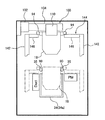
図1は、本発明の実施形態におけるめっき装置の全体配置図を示す。図1に示すように、このめっき装置には、装置フレーム10と、半導体ウェーハ等の基板を収納したカセットを搭載する2台のロードポート12と、各機器の動作を制御する制御部13が備えられている。装置フレーム10の内部には、基板のオリフラやノッチなどの位置を所定の方向に合わせるアライナ14と、めっき処理後の基板を高速回転させて乾燥させるスピン・リンス・ドライヤ(SRD)16と、基板ホルダ18(図2乃至図5参照)が水平に載置されるテーブル20が配置される。さらに、これらのユニットの間で基板を搬送する基板搬送ロボット22が配置されている。
FIG. 1 shows an overall layout of a plating apparatus in an embodiment of the present invention. As shown in FIG. 1, the plating apparatus includes an
テーブル20の上方に位置して、テーブル20上に載置された基板ホルダ18を開閉して基板の該基板ホルダ18への着脱を行う基板ホルダ開閉機構24が配置されている。更に、テーブル20の側方には、基板ホルダ18を起倒させる基板ホルダ起倒機構26が配置されている。
A substrate holder opening /
装置フレーム10の内部には、基板ホルダ起倒機構26の反対側から順に、基板ホルダ18の保管及び一時仮置きを行うストッカ30、基板ホルダ18で保持した基板を純水等の前処理液で前洗浄(前処理)する前水洗槽32、基板ホルダ18で保持した基板にめっきを行うめっき槽34、めっき後の基板を基板ホルダ18と共にリンス水でリンスするリンス槽36、及びリンス後の基板の水切りを行うブロー槽38が配置されている。
Inside the
この例では、前水洗槽32には、内部に純水等の前処理液を保持する1つの前水洗セル32aが、めっき槽34には、内部にめっき液を保持する複数(この例では10列)のめっきセル34aとオーバフロー槽34bが、リンス槽36には、内部にリンス液を保持する1つのリンスセル36aがそれぞれ備えられている。めっきセル34aは例えば電解めっきセルであり、内部にアノード電極を備える。基板ホルダ18は各めっきセル34a内に設置され、この状態で電解めっきを行う。あるいは、めっきセル34aは基板に無電解めっきを行う無電解めっきセルであってもよい。本実施形態では、めっき槽34は1種類のめっき液を用いており、各めっきセル34aからオーバフローしためっき液は共通のオーバフロー槽34bに流れ込むようになっている。ストッカ30は、複数の基板ホルダ18を鉛直方向に並列に保持するように構成されている。ブロー槽38は、エアの吹き付けによって、基板ホルダ18で保持した基板の表面に付着した液滴を除去し乾燥させるように構成されている。
In this example, the
めっき槽34の一側方には、各めっきセル34a内のめっき液を攪拌するパドル(図示せず)を駆動するパドルモータユニット40が設けられている。めっき槽34の他側方には、排気ダクト42が備えられている。
A
基板ホルダ18は、図2乃至図5に示すように、例えば塩化ビニル製で矩形平板状の第1保持部材(固定保持部材)54と、この第1保持部材54にヒンジ56を介して開閉自在に取付けた第2保持部材(可動保持部材)58とを有している。なお、他の構成例として、第2保持部材58を第1保持部材54に対峙した位置に配置し、この第2保持部材58を第1保持部材54に向けて前進させ、また第1保持部材54から離間させることによって第2保持部材58を開閉するようにしてもよい。
As shown in FIGS. 2 to 5, the
第2保持部材58は、基部60と、リング状のシールホルダ62とを有している。シールホルダ62は例えば塩化ビニル製であり、下記の押えリング64との滑りを良くしている。シールホルダ62の上部には、基板ホルダ18が基板Wを保持した時、基板Wの表面外周部に圧接して第2保持部材58と基板Wとの隙間をシールする基板側シール部材66が内方に突出して取付けられている。更に、シールホルダ62の第1保持部材54と対向する面には、基板ホルダ18が基板Wを保持した時、基板側シール部材66の外方位置で第1保持部材54に圧接して第1保持部材54と第2保持部材58との隙間をシールするホルダ側シール部材68が取付けられている。
The second holding
図5に示すように、基板側シール部材66は、シールホルダ62と第1固定リング70aとの間に挟持されてシールホルダ62に取付けられている。第1固定リング70aは、シールホルダ62にボルト等の締結具69aを介して取付けられる。ホルダ側シール部材68は、シールホルダ62と第2固定リング70bとの間に挟持されてシールホルダ62に取付けられている。第2固定リング70bは、シールホルダ62にボルト等の締結具69bを介して取付けられる。
As shown in FIG. 5, the substrate
シールホルダ62の外周部には、段部が設けられ、この段部に、押えリング64がスペーサ65を介して回転自在に装着されている。なお、押えリング64は、第1固定リング70aの外周部によって脱出不能に装着されている。この押えリング64は、酸やアルカリに対して耐食性に優れ、十分な剛性を有する材料から構成される。例えば、押えリング64はチタンから構成される。スペーサ65は、押えリング64がスムーズに回転できるように、摩擦係数の低い材料、例えばPTFEで構成されている。
A step portion is provided on the outer peripheral portion of the
押えリング64の外側方には、複数のクランパ74が押えリング64の円周方向に沿って等間隔で配置されている。これらクランパ74は第1保持部材54に固定されている。各クランパ74は、内方に突出する突出部を有する逆L字状の形状を有している。押えリング64の外周面には、外方に突出する複数の突起部64bが設けられている。これら突起部64bは、クランパ74の位置に対応する位置に配置されている。クランパ74の内方突出部の下面及び押えリング64の突起部64bの上面は、押えリング64の回転方向に沿って互いに逆方向に傾斜するテーパ面となっている。押えリング64の円周方向に沿った複数箇所(例えば3箇所)には、上方に突出する凸部64aが設けられている。これにより、回転ピン(図示せず)を回転させて凸部64aを横から押し回すことにより、押えリング64を回転させることができる。
On the outer side of the
第2保持部材58を開いた状態で、第1保持部材54の中央部に基板Wを挿入し、ヒンジ56を介して第2保持部材58を閉じる。押えリング64を時計回りに回転させて、押えリング64の突起部64bをクランパ74の内方突出部の内部に滑り込ませることで、押えリング64とクランパ74にそれそれぞれ設けたテーパ面を介して、第1保持部材54と第2保持部材58とを互いに締付けて第2保持部材58をロックする。また、押えリング64を反時計回りに回転させて押えリング64の突起部64bをクランパ74から外すことで、第2保持部材58のロックを解くようになっている。第2保持部材58をロックした時、基板側シール部材66の下方突出部は基板Wの表面外周部に圧接される。シール部材66は均一に基板Wに押圧され、これによって基板Wの表面外周部と第2保持部材58との隙間をシールする。同じように、第2保持部材58をロックした時、ホルダ側シール部材68の下方突出部は第1保持部材54の表面に圧接される。シール部材68は均一に第1保持部材54に押圧され、これによって第1保持部材54と第2保持部材58との間の隙間をシールする。
With the second holding
第1保持部材54の上面には、基板Wの大きさにほぼ等しいリング状の突条部82が形成されている。この突条部82は、基板Wの周縁部に当接して該基板Wを支持する環状の支持面80を有している。この突条部82の円周方向に沿った所定位置に凹部84が設けられている。
On the upper surface of the first holding
図3に示すように、凹部84内には複数(図示では12個)の導電体(電気接点)86がそれぞれ配置されている。これら導電体86は、ホルダハンガの第1段部90に設けられた接続端子91から延びる複数の配線にそれぞれ接続されている。第1保持部材54の支持面80上に基板Wを載置した際、この導電体86の端部が基板Wの側方で飛び出して、図5に示す電気接点88の下部に弾性的に接触するようになっている。
As shown in FIG. 3, a plurality (12 pieces in the drawing) of conductors (electrical contacts) 86 are disposed in the
導電体86に電気的に接続される電気接点88は、ボルト等の締結具89を介して第2保持部材58のシールホルダ62に固着されている。この電気接点88は、板ばね形状に形成されている。電気接点88は、基板側シール部材66の外方に位置した、内方に板ばね状に突出する接点部を有している。電気接点88はこの接点部において、その弾性力によるばね性を有して容易に屈曲するようになっている。第1保持部材54と第2保持部材58で基板Wを保持した時に、電気接点88の接点部が、第1保持部材54の支持面80上に支持された基板Wの外周面に弾性的に接触するように構成されている。
An
第2保持部材58の開閉は、図示しないエアシリンダと第2保持部材58の自重によって行われる。つまり、第1保持部材54には通孔54aが設けられ、テーブル20の上に基板ホルダ18を載置した時に該通孔54aに対向する位置にエアシリンダが設けられている。ピストンロッドを伸展させ、通孔54aを通じて押圧棒で第2保持部材58のシールホルダ62を上方に押上げることで第2保持部材58を開き、ピストンロッドを収縮させることで、第2保持部材58をその自重で閉じるようになっている。
The second holding
第1保持部材54の端部には、基板ホルダ18を搬送したり、吊下げ支持したりする際の支持部となる一対のホルダハンガの第1段部90及び第2段部94が外方に突出して設けられている。更に、両側の第1段部90の間にはハンドレバー92が延びている。ストッカ30内では、その周壁上面にホルダハンガの第1段部90を引っ掛けることで、基板ホルダ18を垂直に吊下げ保持する。なお、前水洗槽32、めっき槽34、リンス槽36及びブロー槽38内においても、基板ホルダ18は、ホルダハンガの第1段部90を介してそれらの周壁に吊下げ保持される。
At the end of the first holding
図1に戻って、ストッカ30、前水洗槽32、めっき槽34、リンス槽36、ブロー槽38、及び基板ホルダ起倒機構26の側方に位置して、これらの各機器の間で基板ホルダ18を基板とともに搬送する、例えばリニアモータ方式を採用したトランスポータ100が設けられている。このトランスポータ100は、装置フレーム10等に固定されて水平方向に延びる固定ベース102と、この固定ベース102に沿って水平方向に移動する横移動アーム104とを備えている。トランスポータ100は、基板ホルダ18を保持している時は比較的低速で横移動アーム104を水平方向に移動させ、基板ホルダ18を保持していない時は比較的高速で水平方向に横移動アーム104を移動させるように構成されている。
Returning to FIG. 1, the substrate holder is located between the
横移動アーム104には、図6及び図7に詳細に示すように、基板ホルダ18のハンドレバー92を前後方向から挟んで基板ホルダ18を把持する一対のチャック爪106と、該チャック爪106を互いに近接及び離間する方向に移動させるアクチュエータ108とを有する把持機構110が備えられている。
As shown in detail in FIGS. 6 and 7, the
1つの前水洗セル32aを有する前水洗槽32には、この前水洗槽32の両側に立設した一対のアクチュエータ112を有する前水洗槽用固定リフタ114が設けられている。アクチュエータ112は、ブラケットにより装置フレーム10に固定されている。各アクチュエータ112には、図6及び図7に示すように、このアクチュエータ112に沿って昇降する昇降アーム116が連結されている。昇降アーム116は、アクチュエータ112に内蔵されるモータ及びボールねじによって上下する。この昇降アーム116には、上方に開口した縦断面矩形状(底面と側面を有し上方が開口した形状)の受台118が固定されている。基板Wを保持した基板ホルダ18は、そのホルダハンガの第1段部90が受台118に挿入されることによって前水洗槽用固定リフタ114に支持される。さらに、基板ホルダ18は、アクチュエータ112によって昇降する。
The
同様に、1つのリンスセル36aを有するリンス槽36には、このリンス槽36の両側に立設した一対のアクチュエータ120を有するリンス槽用固定リフタ122が設けられている。各アクチュエータ120には、図6に示すように、このアクチュエータ120によって昇降される昇降アーム124が連結されている。各昇降アーム124には、上方に開口した縦断面矩形状の受台126が固定されている。ブロー槽38の両側には、鉛直方向に延びる一対のアクチュエータ130を有するブロー槽用固定リフタ132が設けられている。各アクチュエータ130には、図6に示すように、このアクチュエータ130によって昇降される昇降アーム134が連結されている。各昇降アーム134には、上方に開口した縦断面矩形状の受台136が固定されている。
Similarly, the rinse
複数のめっきセル34aを有するめっき槽34には、めっき槽用移動リフタ144が設けられている。このめっき槽用移動リフタ144は、装置フレーム10等に固定され、めっき槽34の両側に配置された一対の横移動アクチュエータ140と、鉛直方向に延び、横移動アクチュエータ140によって水平方向に移動される一対の昇降アクチュエータ142とを有している。なお、図6において、横移動アクチュエータ140の一方(手前側)は、図を見やすくするために省略している。昇降アクチュエータ142には、この昇降アクチュエータ142によって昇降する昇降アーム146が連結されており、この昇降アーム146には、上方に開口した縦断面矩形状の受台148が固定されている。基板Wを保持した基板ホルダ18は、そのホルダハンガの第2段部94が受台148に挿入されることによってめっき槽用移動リフタ144に支持される。さらに、基板ホルダ18は、昇降アクチュエータ142によって昇降する。
A plating
ストッカ30には、前記めっき槽用移動リフタ144とほぼ同様な構成のストッカ用移動リフタ154が設けられている。このストッカ用移動リフタ154は、装置フレーム10等に固定され、ストッカ30の両側に配置された一対の横移動アクチュエータ150と、鉛直方向に延び横移動アクチュエータ150によって水平方向に移動する一対の昇降アクチュエータ152とを有している。なお、図6では、横移動アクチュエータ150の一方は省略されている。昇降アクチュエータ152に取り付けられた昇降アームおよび受台(図示せず)が上昇下降する。
The
この例にあっては、トランスポータ100は、基板Wを保持した基板ホルダ18を把持して水平方向に移動させる役割のみを受け持ち、固定リフタ114,122,132および移動リフタ144,154は、トランスポータ100から受取った基板ホルダ18を昇降させる役割を受け持つ。
In this example, the
次に、基板Wを保持した基板ホルダ18を、トランスポータ100から前水洗槽用固定リフタ114で受取って、前水洗槽32内の所定の位置に設置するときの動作について、図8及び図9を参照して説明する。なお、図8においては、受台118は図面の簡略化のため省略する。図9は、基板ホルダ18のホルダハンガの第1段部90及びハンドレバー92、トランスポータ100のチャック爪106、及び前水洗槽用固定リフタ114の受台118のみを模式的に示している。
Next, the operation when the
先ず、図9のステップ1に示すように、前水洗槽用固定リフタ114の受台118を上昇させるとともに、トランスポータ100のチャック爪106で把持した基板ホルダ18を所定の速度で水平方向に移動させる。ステップ2に示すように、昇降アーム116の受台118は、基板ホルダ18の第1段部90に干渉しない所定高さの待機位置で待機し、基板ホルダ18は前水洗槽32の直上方の所定位置で停止する。
First, as shown in Step 1 of FIG. 9, the
次に、ステップ3に示すように、前水洗槽用固定リフタ114の昇降アーム116を上昇させて、受台118を基板ホルダ受取り位置(受台118と第1段部90との隙間が最小となる位置)まで上昇させる。図8の実線は、この昇降アーム116を上昇させ、基板ホルダ18をトランスポータ100から前水洗槽用固定リフタ114に渡す時の状態を模式的に示している。昇降アーム116は、基板ホルダ18のホルダハンガの第1段部90を支持する。ステップ3に示すように、受台118を第1段部90よりわずかに低い位置まで上昇させることができる理由は、昇降アーム116が基板ホルダ18をその両側から支持するように構成されていること、及び左右の昇降アーム116間の距離が基板ホルダ18の第1保持部材54の幅よりも広いからである。
Next, as shown in step 3, the lifting
そして、ステップ4に示すように、チャック爪106を開き、トランスポータ100による基板ホルダ18の把持を解く。これによって、基板ホルダ18は、前水洗槽用固定リフタ114の受台118に保持される。この時に基板ホルダ18に与えられる衝撃が少なくなるよう、受台118に衝撃吸収のクッション機能を持たせてもよい。
Then, as shown in step 4, the
次に、ステップ5に示すように、前水洗槽用固定リフタ114の昇降アーム116を下降させて、受台118及び基板ホルダ18を下降させる。基板ホルダ18のハンドレバー92がトランスポータ100のチャック爪106よりも下方に移動した後は、トランスポータ100は次の処理のために水平移動することができる。
Next, as shown in step 5, the lifting
ステップ6に示すように、受台118は、基板ホルダ18に保持された基板が前水洗槽32内の前処理液(例えば純水)に浸漬されるまで下降する。受台118の下降速度は、液跳ね防止や気泡巻き込み防止等を考慮して設定される。そして、基板ホルダ18を前水洗槽32の所定の位置にセットして、基板の前水洗処理が行われる。このとき、基板ホルダ18は受台118によって支持されたままである(図8の一点鎖線で示す)。前水洗セル32aは1つしかないため、基板Wの処理が終わって基板ホルダ18が次の工程に搬送されない限り、次の基板を処理することができない。従って、前水洗槽用固定リフタ114は、基板ホルダ18を前水洗槽32に対して上昇下降させるだけでなく、前水洗処理中の基板ホルダ18を支持しておく役割も持っている。
As shown in step 6, the
次に、基板Wを保持した基板ホルダ18を前水洗槽32からから引上げて、前水洗槽用固定リフタ114からトランスポータ100に受渡す時の動作を、図10を参照して説明する。図9と同様に、図10は、基板ホルダ18のホルダハンガの第1段部90及びハンドレバー92、トランスポータ100のチャック爪106、及び前水洗槽用固定リフタ114の受台118のみを模式的に示している。
Next, the operation when the
先ず、図10のステップ7に示すように、前水洗槽用固定リフタ114の受台118を上昇させて基板ホルダ18を上昇させるとともに、基板ホルダ18を把持していないトランスポータ100の横移動アーム104を最高速度で水平方向に移動させる。この基板ホルダ18の上昇速度は、基板ホルダ18に付着した処理液の液切りをするための時間も考慮して、例えば100mm/secに設定される。ステップ8に示すように、基板ホルダ18の第1段部90を下から支持した受台118は所定高さの待機位置で待機し、基板ホルダ18を保持していないトランスポータ100の横移動アーム104は前水洗槽32の直上方の所定位置で停止する。
First, as shown in step 7 of FIG. 10, the
次に、ステップ9に示すように、前水洗槽用固定リフタ114の昇降アーム116を上昇させて、受台118を基板ホルダ引渡し位置まで上昇させる。そして、ステップ10に示すように、チャック爪106を閉じ、ハンドレバー92を前後方向から挟持して基板ホルダ18を把持する。
Next, as shown in step 9, the lifting
次に、ステップ11に示すように、昇降アーム116を下降させて、受台118を待機位置まで下降させ、次の基板ホルダを受取るまで待機する。基板ホルダ18を保持したトランスポータ100は、ステップ12に示すように、次の処理槽まで基板ホルダ18を水平方向に移動させる。この時、ステップ12に示すように、昇降アーム116を下降させて、受台118を下端停止位置まで下降させるようにしてもよい。
Next, as shown in step 11, the elevating
水洗槽用固定リフタ114が基板ホルダ18を前水洗槽32から引き上げる動作が終了すると同時に、トランスポータ100が基板ホルダ18を受け取ることが望ましい。これは、空中に放置された基板Wの乾燥や酸化等を避けるためである。しかしながら、トランスポータ100が他の基板ホルダを搬送している場合や、トランスポータ100の横移動アーム104が前水洗槽32から離れている場合には、トランスポータ100が直ちに前水洗槽32に到達できないこともある。そこで、制御部13は、基板ホルダ18の引き上げが終了したと同時にトランスポータ100が前水洗槽32に到達可能かどうかを判断するように構成されている。この判断は、予め設定されている各動作所要時間に基づいて行われる。
It is desirable that the
トランスポータ100が前水洗槽32に到達可能と判断された場合には、前水洗槽用固定リフタ114は基板ホルダ18の引き上げをすぐに開始する。その場合に、前水洗槽用固定リフタ114が基板ホルダ18の引き上げを終了するまでにトランスポータ100が前水洗槽32に到達するように、制御部13はトランスポータ100の横移動アーム104の走行の開始タイミングを制御する。トランスポータ100が前水洗槽32に到達不可能と判断された場合には、制御部13はトランスポータ100の予想される到達時間と、基板ホルダ18の引き上げに要する時間とに基づいて、基板ホルダ18の引き上げ開始時間を計算する。引き上げ開始時間に達するまで、前水洗槽用固定リフタ114は基板ホルダ18の引き上げを開始せず待機する。このように、トランスポータ100が他の基板ホルダの搬送を行っているか、又は前水洗槽32へ走行している間に並行して前水洗槽用固定リフタ114が基板ホルダ18を前水洗槽32から引き上げる動作を開始することができる。したがって、搬送所要時間が短縮され、スループットが向上する。
When it is determined that the
トランスポータ100が一度に搬送できるのは1台の基板ホルダ18のみである。したがって、前処理槽32を含む複数の処理槽で基板処理が同時に終了した場合は、制御部13は、基板ホルダ18を引き上げるべき1つの処理槽を選択する。どの処理槽を選択すべきかは、処理後の基板Wの処理槽内での許容される滞在時間に基づいて判断される。
The
基板ホルダ18の引き上げが終了したと同時にトランスポータ100が前水洗槽32に到達可能かどうかの判断は、(1)トランスポータ100の横移動アーム104が到達するまでに所要する時間、及び(2)前水洗槽用固定リフタ114が基板ホルダ18を前水洗槽32から引上げるのに所要する時間、等を基に行われる。これらの時間は、予め計測して制御部13にパラメータとして設定される。判断のタイミングは、例えば、前水洗槽32で基板Wに対する前処理(前水洗)を開始した時点、又はトランスポータ100が他の基板ホルダの搬送を開始した時点である。
Whether or not the
これにより、前水洗槽用固定リフタ114が上昇を終了するタイミングが、トランスポータ100の横移動アーム104が前水洗槽32に到着するタイミングと一致する。したがって、基板Wを前水洗槽32から取り出すときの基板ホルダ18の前水洗槽用固定リフタ114からトランスポータ100の横移動アーム104への受渡しを、ロスタイムなくスムーズに行うことができる。
As a result, the timing at which the pre-wash tank fixed
また、前水洗槽用固定リフタ114が基板ホルダ18を前水洗槽32へセットする場合にあっても同様の動作制御が行われる。すなわち、予め計算しておいた移動開始タイミングの時刻が経過したら、前水洗槽用固定リフタ114は待機位置への移動を開始する。つまり、トランスポータ100の横移動アーム104が前水洗槽32に到達する前に、前水洗槽用固定リフタ114の受台118が待機位置で待機するように、前水洗槽用固定リフタ114の動作開始タイミングを制御する。
The same operation control is performed even when the pre-rinsing tank fixed
これによって、基板Wを前水洗槽32内に投入するときの基板ホルダ18のトランスポータ100から前水洗槽用固定リフタ114への受渡しを、ロスタイムなくスムーズに行うことができる。
As a result, the delivery from the
なお、基板Wを保持した基板ホルダ18を、トランスポータ100からリンス槽用固定リフタ122で受取って、リンス槽36の所定の位置に設置する時や、トランスポータ100からブロー槽用固定リフタ132で受取って、ブロー槽38の所定の位置に設置する時にあっても、前述とほぼ同様の動作制御が行われるので、その重複する説明を省略する。
The
上述のように、前水洗槽用固定リフタ114、リンス槽用固定リフタ122、ブロー槽用固定リフタ132は、それぞれ対応する処理槽のセルが1つだけなので、水平方向に移動せず昇降だけを行う固定式のリフタが用いられている。
As described above, the pre-rinsing tank fixed
次に、基板Wを保持した基板ホルダ18を、トランスポータ100からめっき槽用移動リフタ144で受取って、めっき槽34の1つのめっきセル34aの所定位置に設置するときの動作について、図11及び図12を参照して説明する。めっき槽34は、通常複数のめっきセル34aを有している。各めっきセル毎に固定リフタを設置すると、固定リフタが多数林立して部品点数が増えるだけでなく、めっきセル34a槽内の部品の調整や交換などのメンテナンスの妨げになってしまう。そこで、この例のように、移動リフタを使用することで、装置の簡素化とメンテナンス空間の確保を図ることができる。
Next, with respect to the operation when the
図11の実線は、めっき槽用移動リフタ144の昇降アーム146を基板ホルダ受取り位置まで上昇させて、基板ホルダ18をトランスポータ100からめっき槽用移動リフタ144に渡す時の状態を模式的に示している。昇降アーム146は、基板ホルダ18のホルダハンガの第2段部94を支持する。なお、図11においては、昇降アーム146に取り付けられた受台148は省略する。図11の一点鎖線は、基板Wを保持した基板ホルダ18がめっき槽用移動リフタ144によって下降され、めっきセル34aに浸漬されている状態を示している。
The solid line in FIG. 11 schematically shows a state where the
図12は、基板ホルダ18のホルダハンガの第2段部94及びハンドレバー92、トランスポータ100のチャック爪106、及びめっき槽用移動リフタ144の受台148のみを模式的に示している。
FIG. 12 schematically shows only the
先ず、図12のステップ1に示すように、めっき槽用移動リフタ144の昇降アクチュエータ142を横移動アクチュエータ140によって水平方向に移動させて、めっき槽用移動リフタ144の受台148を所定のめっきセル34aの側方に位置させ、さらに昇降アクチュエータ142によって受台148を上昇させる。一方、トランスポータ100によって基板ホルダ18を所定の速度で水平方向に移動させる。ステップ2に示すように、めっき槽用移動リフタ144の受台148は、基板ホルダ18のホルダハンガの第2段部94に干渉しない所定高さの待機位置で待機し、トランスポータ100で把持した基板ホルダ18は1つのめっきセル34aの直上方の所定位置で停止する。
First, as shown in Step 1 of FIG. 12, the elevating
次に、ステップ3に示すように、めっき槽用移動リフタ144の昇降アーム146を上昇させて、受台148を基板ホルダ受取り位置まで上昇させる。図11の実線は、めっき槽用移動リフタ144の受台148を基板ホルダ受取り位置まで上昇させて、基板ホルダ18をトランスポータ100からめっき槽用移動リフタ144に渡す時の状態を模式的に示している。そして、ステップ4に示すように、チャック爪106を開き、トランスポータ100による基板ホルダ18の把持を解く。これによって、基板ホルダ18は、めっき槽用移動リフタ144の受台148に保持される。前水洗槽用固定リフタ114の受台118と同様に、めっき槽用移動リフタ144の受台148にも衝撃吸収のクッション機能を持たせるようにしてもよい。
Next, as shown in step 3, the lifting
次に、ステップ5に示すように、めっき槽用移動リフタ144の昇降アーム146を下降させて、受台148を下降させる。前水洗槽用固定リフタ114の動作で説明したように、基板ホルダ18のハンドレバー92がトランスポータ100のチャック爪106よりも下方に移動した後は、トランスポータ100は次の処理のために水平移動することができる。
Next, as shown in step 5, the lifting
ステップ6に示すように、受台148が下降することによって、基板ホルダ18に保持された基板がめっきセル34a内のめっき液に浸漬される。受台148の下降速度は、液跳ね防止や気泡巻き込み防止等を考慮して設定される。基板ホルダ18のホルダハンガの第1段部90は、図11に示す一つのめっきセル34aの両側に設けられた一対のめっき槽側受台35に当接し、これらのめっき槽側受台35によって基板ホルダ18が支持される。これによって、基板ホルダ18を一つのめっきセル34aの所定の位置にセットする。なお、めっき槽側受台35も、底面と側面を有し上方が開口した形状となっている。めっき槽側受台35は、図6においては省略されている。
As shown in step 6, when the
そして、ステップ7に示すように、受台148を更に下端停止位置まで下降させて停止させる。更に、必要に応じて、ステップ8に示すように、横移動アクチュエータ140により昇降アクチュエータ142を介して受台148を、例えば、めっきが終了して基板ホルダを取出す他のめっきセル34aの側方に移動させる。
Then, as shown in step 7, the
次に、基板Wを保持した基板ホルダ18を、めっき槽34の1つのめっきセル34aからから引上げて、めっき槽用移動リフタ144からトランスポータ100に渡す時の動作を、図13を参照して説明する。図13は、基板ホルダ18のホルダハンガの第2段部94及びハンドレバー92、トランスポータ100のチャック爪106、及びめっき槽用移動リフタ144の受台148のみを模式的に示している。
Next, the operation when the
先ず、図12のステップ8に示すように、横移動アクチュエータ140によって昇降アクチュエータ142を介して受台148を横方向に移動させ、めっきが終了して基板ホルダを取出すめっきセル34aの側方でめっき槽側受台35よりも下方に位置させる。この状態で、図13のステップ9に示すように、めっき槽用移動リフタ144の受台148を上昇させ、基板ホルダ18のホルダハンガの第2段部94を受台148で下から支持して基板ホルダ18を上昇させる。この基板ホルダ18の上昇速度は、例えば30〜200mm/secに設定される。一方、基板ホルダ18を把持していないトランスポータ100の横移動アーム104を最高速度で水平方向に移動させる。ステップ10に示すように、基板ホルダ18を支持した受台148は所定高さの待機位置で待機し、基板ホルダ18を保持していないトランスポータ100のチャック爪106はめっきセル34aの直上方の所定位置で停止する。
First, as shown in Step 8 of FIG. 12, the
次に、ステップ11に示すように、めっき槽用移動リフタ144の昇降アーム146を上昇させて、受台148を基板ホルダ引渡し位置まで上昇させる。そして、ステップ12に示すように、チャック爪106を閉じ、ハンドレバー92を前後方向から挟持して基板ホルダ18を把持する。
Next, as shown in step 11, the lifting
次に、ステップ13に示すように、めっき槽用移動リフタ144の昇降アーム146を下降させて、受台148を待機位置まで下降させ、次の基板ホルダを受取るまで待機する。基板ホルダ18を保持したトランスポータ100は、ステップ14に示すように、次の処理槽まで基板ホルダ18を水平方向に移動させる。
Next, as shown in
その後の動作としては、ステップ15,16に示すように、新しくめっきを行う基板がない場合には、次にめっきが終了するめっきセルの側方で、めっき槽側受台35よりも下方の位置に受台148を移動させて待機する。
As a subsequent operation, as shown in
以上説明しためっき槽用移動リフタ144の構成により、一対の昇降アクチュエータ142を横移動アクチュエータ140によって水平方向に移動させることで、複数のめっきセル34aのうちの任意の1つにおいて、従来トランスポータで行っていた基板ホルダ18の上昇下降を行うことができる。なお、めっき槽のめっきセルの数が、例えば2列など、少数の場合は、基板ホルダを選択して保持できるようにした、アクチュエータ等の選択機構を有する固定リフタを使用しても良い。
With the configuration of the plating tank moving lifter 144 described above, the conventional transporter can be used in any one of the plurality of plating
トランスポータ100は、めっき装置の天井側壁に設置することが好ましい。このような配置によって、トランスポータ100の組立や調整の手間が増えるものの、スペース効率をよくすることができる。また、めっき槽用移動リフタ144の昇降アクチュエータ142は、めっき槽34から離して配置することが好ましく、これによって、めっき液が飛散しても昇降アクチュエータ142に付着し難くすることができる。
The
ストッカ用移動リフタ154も、めっき槽用移動リフタ144と同様の構成となっている。ストッカ30は、複数のストッカ用受台を備えており、基板ホルダ18のホルダハンガの第1段部90を支持して複数の基板ホルダ18を並べて吊り下げ保管する。ストッカ30から基板ホルダ18を取り出す動作は次のようにして行われる。まず、取り出すべき基板ホルダ18の側方の位置に昇降アームに取り付けられた受台(図示せず)が位置するように、横移動アクチュエータ150が駆動する。次に昇降アクチュエータ152が駆動して、受台が基板ホルダ18のホルダハンガの第2段部94を支持して基板ホルダ18を持ち上げる。このようにして、一対の昇降アクチュエータ152を横移動アクチュエータ150によって水平方向に移動させることで、ストッカ30内の任意の保管位置において、従来トランスポータで行っていた基板ホルダ18の上昇下降を行うことができる。
The
図14は、基板ホルダ起倒機構26を示す斜視図である。図14に示すように、基板ホルダ起倒機構26は、テーブル20の両側に立設した一対の昇降アクチュエータ28と、昇降アクチュエータ28を水平方向に移動させるための一対の横移動アクチュエータ29と、昇降アクチュエータ28によって上下動する一対の支持ピン(支持部材)31を有している。支持ピン31は、ピン駆動アクチュエータ33によって互いに近接する方向及び離間する方向に伸縮する。図15に示すように、この支持ピン31を基板ホルダ18の第2段部94の側面に設けられたピン挿入孔95(図2及び図3参照)に挿入することによって、基板ホルダ起倒機構26は基板ホルダ18を回転自在に支持することができる。テーブル20には、図14の矢印に示す方向にスライド可能なスライダー25が設けられている。
FIG. 14 is a perspective view showing the substrate holder raising / lowering mechanism 26. As shown in FIG. 14, the substrate holder raising / lowering mechanism 26 includes a pair of elevating
トランスポータ100は、そのチャック爪106で基板ホルダ18のハンドレバー92を挟むことによって基板ホルダ18を保持する。トランスポータ100は、上昇位置にある支持ピン31を基板ホルダ18のピン挿入孔95に挿入できる位置まで基板ホルダ18を移動させる。この状態で支持ピン31をピン駆動アクチュエータ33によって突出させてピン挿入孔95に挿入する(図15参照)。
The
図16は、めっき処理が終了した後に基板ホルダ18を基板ホルダ起倒機構26によって水平に倒してテーブル20に載置する動作を説明する図である。ステップ1では、チャック爪106を開くことによって、トランスポータ100は基板ホルダ18のハンドレバー92を解放する。ステップ2では、支持ピン31によって支持された基板ホルダ18を昇降アクチュエータ28により下降させ、基板ホルダ18の先端をスライダー25の受け面に接触させる。基板ホルダ18がこの位置まで下降する間に、基板ホルダ18のハンドレバー92は、トランスポータ100のチャック爪106よりも下方に下がるので、トランスポータ100は次の処理のために水平移動できる。
FIG. 16 is a diagram for explaining the operation of placing the
ステップ3,4に示すように、横移動アクチュエータ29と昇降アクチュエータ28を連動して作動させて、支持ピン31をさらに下方へ動かす。支持ピン31の下方への移動に伴って基板ホルダ18は支持ピン31を中心に回転し、これによって基板ホルダ18は鉛直方向に対してさらに傾く。基板ホルダ18の先端がスライダー25から外れないように、横移動アクチュエータ29と昇降アクチュエータ28は連動して動作する。スライダー25は、錘27によってブロー槽38に向かって付勢されている。昇降アクチュエータ28により支持ピン31をさらに下降させると、スライダー25がロードポート側へスライドし、基板ホルダ18はさらに傾斜し(ステップ5)、やがて水平姿勢になる(ステップ6)。図17は、基板ホルダ18が水平姿勢にある状態を示す図である。スライダー25自体も回転可能に構成されており、基板ホルダ18の先端がスライダー25から外れないようになっている。なお、スライダー25の動きを別のアクチュエータで制御しながらスライダー25を動かしてもよい。
As shown in Steps 3 and 4, the
テーブル20の上方には、基板ホルダ18の第2保持部材(可動保持部材)58を第1保持部材(固定保持部材)54に対してロックするための基板ホルダ開閉機構24が設けられる(図1参照)。基板のめっき後は、基板ホルダ開閉機構24によって第2保持部材58のロックが解除され、さらに基板搬送ロボット22によって基板が基板ホルダ18から取り除かれる。
A substrate holder opening /
新たにめっき処理される基板が基板ホルダ18に保持されると、昇降アクチュエータ28は再び支持ピン31を上昇させ、基板ホルダ18を鉛直姿勢に戻す。支持ピン31の上昇位置で基板ホルダ18のハンドレバー92をトランスポータ100のチャック爪106が挟持できるように、トランスポータ100の横移動アーム104の水平位置が制御される。スライダー25はブロー槽38に向かって付勢されているのでスライダー25は基板ホルダ18の先端から外れることなく基板ホルダ18の動きに追従する。トランスポータ100のチャック爪106がハンドレバー92を挟持すると、支持ピン31が後退して基板ホルダ18がトランスポータ100に渡される。
When the substrate to be newly plated is held by the
次に、上記のように構成しためっき装置によるめっき処理を説明する。先ず、ストッカ30内に鉛直方向に収容されている基板ホルダ18を、ストッカ用移動リフタ154で保持して上昇させ、トランスポータ100の横移動アーム104に渡す。基板ホルダ18を把持した横移動アーム104は、水平方向に移動して、基板ホルダ起倒機構26に基板ホルダ18を渡す。基板ホルダ起倒機構26は、アクチュエータ28に設けた一対の支持ピン31で基板ホルダ18を支持しながら、上述のように基板ホルダ18を鉛直姿勢から水平姿勢に転換し、テーブル20の上に載置する。そして、テーブル20に載置された基板ホルダ18を開いた状態にしておく。
Next, the plating process performed by the plating apparatus configured as described above will be described. First, the
基板搬送ロボット22は、ロードポート12に搭載したカセットから基板を1枚取出し、アライナ14に載せる。アライナ14はオリフラやノッチなどの位置を所定の方向に合わせる。基板搬送ロボット22は、基板をアライナ14から取り出し、テーブル20上に載置された基板ホルダ18に挿入する。この状態で、基板ホルダ18を閉じ、しかる後、基板ホルダ開閉機構24で基板ホルダ18をロックする。
The
次に、基板ホルダ起倒機構26は、アクチュエータ28によって一対の支持ピン31(図14参照)を上昇させて、基板ホルダ18を水平姿勢から鉛直姿勢に転換する。トランスポータ100の横移動アーム104は、この起立した状態の基板ホルダ18を把持し、水平方向に移動して、前水洗槽用固定リフタ114に基板ホルダ18を渡す。基板ホルダ18を受取った前水洗槽用固定リフタ114は、基板ホルダ18を下降させて、水洗槽32の所定の位置にセットし、これによって、基板Wの前水洗を行う。基板Wの前水洗が終了した後、前水洗槽用固定リフタ114は、基板ホルダ18を上昇させて、トランスポータ100の横移動アーム104に基板ホルダ18を渡す。
Next, the substrate holder raising / lowering mechanism 26 raises the pair of support pins 31 (see FIG. 14) by the
トランスポータ100の横移動アーム104は、水平方向に移動して、めっき槽用移動リフタ144に基板ホルダ18を渡す。基板ホルダ18を受取っためっき槽用移動リフタ144は、基板ホルダ18を下降させて、めっき槽34の1つのめっきセル34aのめっき槽側受台にセットし、これによって、基板Wのめっきを行う。めっきが終了した後、めっき槽用移動リフタ144は、基板ホルダ18を上昇させて、トランスポータ100の横移動アーム104に基板ホルダ18を渡す。
The
トランスポータ100の横移動アーム104は、水平方向に移動して、リンス用固定リフタ122に基板ホルダ18を渡す。基板ホルダ18を受取ったリンス槽用固定リフタ122は、基板ホルダ18を下降させて、リンス槽36の所定の位置にセットし、これによって、基板Wのめっき後のリンスを行う。リンスが終了した後、リンス槽用固定リフタ122は、基板ホルダ18を上昇させて、トランスポータ100の横移動アーム104に基板ホルダ18を渡す。
The
トランスポータ100の横移動アーム104は、水平方向に移動して、ブロー槽用固定リフタ132に基板ホルダ18を渡す。基板ホルダ18を受取ったブロー槽用固定リフタ132は、基板ホルダ18を下降させて、ブロー槽38の所定の位置にセットし、エアの吹き付けによって、基板ホルダ18で保持した基板Wの表面に付着した水滴を除去し乾燥させる。ブロー処理が終了した後、ブロー槽用固定リフタ132は、基板ホルダ18を上昇させて、トランスポータ100の横移動アーム104に基板ホルダ18を渡す。
The
トランスポータ100の横移動アーム104は、水平方向に移動して、基板ホルダ起倒機構26に基板ホルダ18を渡す。基板ホルダ起倒機構26は、前述とほぼ同様にして、基板ホルダ18をテーブル20の上に水平に載置する。基板搬送ロボット22は、基板ホルダ18から処理後の基板を取出し、この処理後の基板をスピン・リンス・ドライヤ16に搬送する。スピン・リンス・ドライヤ16は基板を高速で回転させて基板を乾燥させる。基板搬送ロボット22は、乾燥された基板をスピン・リンス・ドライヤ16から取り出し、ロードポート12のカセットに戻す。これによって、1枚の基板に対する処理を終了する。
The
全てのめっきセルに順次基板ホルダ18を投入して複数の基板を連続してめっき処理することも可能である。この場合には、まず始めに、めっき槽用移動リフタ144は、1つのめっきセル34aに基板ホルダ18を設置した後、受台148を次のめっきセル34aの側方まで移動させて、次の基板ホルダ18を受け取る。1つのめっきセル34aでめっき処理が終了すると、めっき槽用移動リフタ144が基板ホルダ18をそのめっきセル34aから持ち上げる。次の基板ホルダ18がそのめっきセル34aに運ばれてくるまで受台148はその場で待機する。これ以上新たにめっきを行う基板がなくなると、めっき槽用移動リフタ144は、めっきされた基板を保持する基板ホルダ18を持ち上げた後、次にめっきが終了するめっきセル34aの側方まで受台148を移動させて待機する。このようにして連続めっき処理が行われる。
It is also possible to sequentially put the
図18は、他のタイプの基板ホルダ18aの概要を示す。この基板ホルダ18aは、2枚の基板Wを横方向に並べて同時に保持するように構成されている。このように、2枚の基板Wを同時に保持する基板ホルダ18aを使用することによって、スループットをほぼ2倍に向上させることができる。なお、1枚の基板のみを処理する場合には、処理すべき基板とともにダミー基板が基板ホルダ18aによって保持される。ダミー基板は、例えばアライナ14の上方に保管される。
FIG. 18 shows an outline of another type of
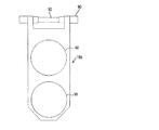
図19は、更に他のタイプの基板ホルダ18bの概要を示す。この基板ホルダ18bは、2枚の基板Wを縦方向に並べて同時に保持するように構成されている。これによっても、スループットをほぼ2倍に向上させることができる。
FIG. 19 shows an outline of yet another type of
図20は、更に他の基板ホルダ18cで基板Wを保持した状態の要部拡大図である。図20に示すように、基板ホルダ18cは、ヒンジ(図示せず)を介して互いに開閉自在な、樹脂材(例えば、HTPVC)からなる板状の第1保持部材212と第2保持部材214を有している。第1保持部材212には開口穴212aが設けられ、第2保持部材214には開口穴214aが設けられている。そして、第1保持部材212と第2保持部材214は、ヒンジを介して閉じた状態(重ね合わせた状態)で、一対のクランプ216によって保持される。クランプ216は、開閉自在に構成されており、樹脂材(例えば、HTPVC)から形成される。
FIG. 20 is an enlarged view of the main part in a state where the substrate W is held by still another
第1保持部材212には、開口穴212aに沿って延びるシールリング218が取付けられている。このシールリング218は第2保持部材214に対向するように配置されている。第2保持部材214には、開口穴214aに沿って延びるシールリング220が取付けられている。このシールリング220は第1保持部材212に対向するように配置されている。シールリング218,220は、ゴム材(例えば、シリコーンゴムやフッ素ゴム)からなる。第2保持部材214の第1保持部材212に対向する面には、Oリング222が取付けられている。このOリング222はシールリング220の外側に配置されている。
A
シールリング218,220は、その内周側に環状のシール部218a,220aをそれぞれ有する。これらシール部218a,220aは、それぞれ開口穴212a,214aに沿って延びており、互いに対向するように配置されている。第1保持部材212と第2保持部材214との間に基板Wを介在させて重ね合わせた状態で、シール部218a,220aが基板Wの外周部をその両側から押圧して密接する。これによって、シール部218a,220a及びOリング222で囲まれた領域は、めっき液の浸水しない水密領域とされる。
The seal rings 218 and 220 respectively have
第1保持部材212には複数の導電プレート224が設けられている。これらの複数の導電プレート224は、上述した水密領域内に配置されている。導電プレート224の内の半数は、導電ピン226を介して、基板Wの一方の面(例えば表面)に導通する。導電プレート224内の残りの半数は、導電ピン226を介して、基板Wの他方の面(例えば裏面)に導通する。導電プレート224は、基板ホルダ18cのハンド(図示せず)に設けた接続端子に電気的に接続される。
The
上記基板ホルダ18cにおいて、第1保持部材212と第2保持部材214とを開いた状態で、第1保持部材212の所定位置に基板Wを載置する。そして第1保持部材212と第2保持部材214とをヒンジを介して閉じ、更に一対のクランプ216をそれぞれ回動させて、第1保持部材212と第2保持部材214の両辺を一対のクランプ216の溝216aに嵌挿する。これにより、基板Wは、第1保持部材212と第2保持部材214で保持される。
In the
このように、基板Wを第1保持部材212と第2保持部材214で保持すると、シールリング218,220のシール部218a,220aとOリング222で囲まれた領域は、めっき液が浸水しない水密状態に密閉される。基板Wのシール部218a,220aよりも外側の部分がこの密閉空間内に位置し、基板Wの両面のシール部218a,220aよりも内側の部分がめっき液に接触する。また、複数の導電プレート224は、ハンドから延びる外部電極に接続される。
As described above, when the substrate W is held by the first holding
この例の基板ホルダ18cによれば、基板Wの表面及び裏面を同時に露出させて基板Wを保持することができ、これによって、基板Wの表面及び裏面にめっきを同時に行うことができる。あるいは、この例の基板ホルダ18cを用いて、2枚の基板を裏面どうしを合わせるように重ねて、それぞれの基板の表面をめっき液に接触させてめっきするようにしても良い。
According to the
これまで本発明の好ましい実施形態について説明したが、本発明は上述の実施形態に限定されず、その技術的思想の範囲内において種々異なる形態にて実施されてよいことは言うまでもない。 The preferred embodiments of the present invention have been described above, but the present invention is not limited to the above-described embodiments, and it goes without saying that the present invention may be implemented in various forms within the scope of the technical idea.
13 制御部
14 アライナ
16 スピン・リンス・ドライヤ
18 基板ホルダ
20 テーブル
24 基板ホルダ開閉機構
26 基板ホルダ起倒機構
30 ストッカ
32 前水洗槽
32a 前水洗セル
34 めっき槽
34a めっきセル
36 リンス槽
36a リンスセル
38 ブロー槽
54 第1保持部材
58 第2保持部材
62 シールホルダ
64 押えリング
66,68 シール部材
70a,70b 固定リング
74 クランパ
90 ホルダハンガ
92 ハンドレバー
100 トランスポータ
102 固定ベース
104 横移動アーム
106 チャック爪
110 把持機構
112,120,130 アクチュエータ
114 前水洗槽用固定リフタ
116,124,134,146 昇降アーム
118,126,136,148 受台
122 リンス槽用固定リフタ
132 ブロー槽用固定リフタ
140,150 横移動アクチュエータ
142,152 昇降アクチュエータ
144 めっき槽用移動リフタ
154 ストッカ用移動リフタ
13
Claims (9)
前記基板ホルダで保持した基板を処理する処理槽と、
前記基板を保持した基板ホルダを把持して水平方向に搬送するトランスポータと、
前記基板を保持した基板ホルダを前記トランスポータから受取り下降させて前記処理槽の内部に投入し、処理後の基板を保持した前記基板ホルダを上昇させて前記トランスポータに渡すリフタと、
前記トランスポータ及び前記リフタの動作を制御する制御部を有することを特徴とするめっき装置。 A substrate holder for holding the substrate in a vertical direction;
A processing tank for processing the substrate held by the substrate holder;
A transporter that grips the substrate holder holding the substrate and conveys it horizontally;
A lifter for receiving and lowering the substrate holder holding the substrate from the transporter and putting it into the processing tank, raising the substrate holder holding the processed substrate and passing it to the transporter;
A plating apparatus comprising a control unit for controlling operations of the transporter and the lifter.
前記リフタは、前記基板ホルダを上下動させる昇降アクチュエータと、前記昇降アクチュエータを複数の前記セル間で水平方向に移動させる横移動アクチュエータを備えることを特徴とする請求項1に記載のめっき装置。 A plurality of the treatment tanks, at least one of the treatment tanks has a plurality of cells for performing a common treatment;
The plating apparatus according to claim 1, wherein the lifter includes a lifting actuator that moves the substrate holder up and down, and a lateral movement actuator that moves the lifting actuator horizontally between the plurality of cells.
前記複数の基板ホルダの各々で保持した基板を処理する処理槽と、
前記複数の基板ホルダのうちの1つを把持して水平方向に搬送するトランスポータと、
前記複数の基板ホルダを保管しておくストッカと、
前記ストッカに保管している前記複数の基板ホルダのうちの1つを上昇させて前記トランスポータに渡すリフタとを備え、
前記リフタは、前記複数の基板ホルダのうちの1つを上下動させる昇降アクチュエータと、前記昇降アクチュエータを前記ストッカ内の複数の基板ホルダ保管位置の間で水平移動させる横移動アクチュエータを有することを特徴とするめっき装置。 A plurality of substrate holders for holding the substrate in a vertical direction;
A processing tank for processing a substrate held by each of the plurality of substrate holders;
A transporter that grips one of the plurality of substrate holders and transports it horizontally;
A stocker for storing the plurality of substrate holders;
A lifter that raises one of the plurality of substrate holders stored in the stocker and passes it to the transporter;
The lifter includes a lift actuator that moves one of the plurality of substrate holders up and down, and a lateral movement actuator that horizontally moves the lift actuator between a plurality of substrate holder storage positions in the stocker. And plating equipment.
前記基板ホルダで保持した基板を処理する処理槽と、
前記基板ホルダを把持して水平方向に搬送するトランスポータと、
前記基板ホルダを前記トランスポータに渡し、前記トランスポータから受け取る基板ホルダ起倒機構を有し、
前記基板ホルダ起倒機構は、前記基板ホルダを回動可能に支持する支持部材と、前記支持部材を昇降可能に支持する昇降アクチュエータとを備えており、
前記基板ホルダ起倒機構は、前記昇降アクチュエータによって前記支持部材を下降させることによって前記基板ホルダを鉛直姿勢から水平姿勢に転換し、前記昇降アクチュエータによって前記支持部材を上昇させることによって前記基板ホルダを水平姿勢から鉛直姿勢に転換するように構成されていることを特徴とするめっき装置。 A substrate holder for holding the substrate in a vertical direction;
A processing tank for processing the substrate held by the substrate holder;
A transporter that grips the substrate holder and transports it horizontally;
Passing the substrate holder to the transporter, and having a substrate holder tilting mechanism for receiving from the transporter,
The substrate holder raising / lowering mechanism includes a support member that rotatably supports the substrate holder, and an elevating actuator that supports the support member to be movable up and down,
The substrate holder raising / lowering mechanism changes the substrate holder from a vertical posture to a horizontal posture by lowering the support member by the lift actuator , and horizontally moves the substrate holder by raising the support member by the lift actuator. A plating apparatus configured to change from a posture to a vertical posture.
Priority Applications (5)
| Application Number | Priority Date | Filing Date | Title |
|---|---|---|---|
| JP2013041493A JP6077886B2 (en) | 2013-03-04 | 2013-03-04 | Plating equipment |
| US14/194,514 US9624594B2 (en) | 2013-03-04 | 2014-02-28 | Plating apparatus |
| TW103107008A TWI598472B (en) | 2013-03-04 | 2014-03-03 | Plating apparatus |
| KR1020140025107A KR102080207B1 (en) | 2013-03-04 | 2014-03-03 | Plating apparatus |
| US15/450,873 US10077504B2 (en) | 2013-03-04 | 2017-03-06 | Plating apparatus |
Applications Claiming Priority (1)
| Application Number | Priority Date | Filing Date | Title |
|---|---|---|---|
| JP2013041493A JP6077886B2 (en) | 2013-03-04 | 2013-03-04 | Plating equipment |
Publications (3)
| Publication Number | Publication Date |
|---|---|
| JP2014169475A JP2014169475A (en) | 2014-09-18 |
| JP2014169475A5 JP2014169475A5 (en) | 2015-11-19 |
| JP6077886B2 true JP6077886B2 (en) | 2017-02-08 |
Family
ID=51420276
Family Applications (1)
| Application Number | Title | Priority Date | Filing Date |
|---|---|---|---|
| JP2013041493A Expired - Fee Related JP6077886B2 (en) | 2013-03-04 | 2013-03-04 | Plating equipment |
Country Status (4)
| Country | Link |
|---|---|
| US (2) | US9624594B2 (en) |
| JP (1) | JP6077886B2 (en) |
| KR (1) | KR102080207B1 (en) |
| TW (1) | TWI598472B (en) |
Families Citing this family (20)
| Publication number | Priority date | Publication date | Assignee | Title |
|---|---|---|---|---|
| JP6239417B2 (en) | 2014-03-24 | 2017-11-29 | 株式会社荏原製作所 | Substrate processing equipment |
| SG11201700244WA (en) | 2014-07-24 | 2017-02-27 | Stoneage Inc | Flexible tube cleaning lance positioner frame apparatus |
| US10024613B2 (en) * | 2014-07-24 | 2018-07-17 | Stoneage, Inc. | Flexible tube cleaning lance positioner frame apparatus |
| JP2016089204A (en) * | 2014-10-31 | 2016-05-23 | ダイハツ工業株式会社 | Electrodeposition coating facility |
| JP6675257B2 (en) * | 2016-04-14 | 2020-04-01 | 株式会社荏原製作所 | Plating apparatus and plating method |
| CN109689944B (en) * | 2016-09-08 | 2022-01-28 | 株式会社荏原制作所 | Substrate holder, plating device, and substrate holding method |
| US11769686B2 (en) | 2016-09-29 | 2023-09-26 | Intel Corporation | Methods and apparatus for electroless plating dispense |
| TW201836720A (en) * | 2016-12-19 | 2018-10-16 | 英商P2I有限公司 | Improvements relating to surface modification |
| JP6727117B2 (en) * | 2016-12-22 | 2020-07-22 | 株式会社荏原製作所 | Substrate attachment/detachment device, plating device, substrate attachment/detachment device control device, storage medium storing a program for causing a computer to execute the method |
| JP6860406B2 (en) | 2017-04-05 | 2021-04-14 | 株式会社荏原製作所 | Semiconductor manufacturing equipment, failure prediction method for semiconductor manufacturing equipment, and failure prediction program for semiconductor manufacturing equipment |
| JP6979900B2 (en) * | 2018-02-13 | 2021-12-15 | 株式会社荏原製作所 | A storage medium that stores a board holding member, a board processing device, a control method for the board processing device, and a program. |
| JP7100556B2 (en) * | 2018-10-05 | 2022-07-13 | 株式会社荏原製作所 | A device for causing the board holder to hold the board and / or releasing the holding of the board by the board holder, and a plating device having the same device. |
| CN109706510B (en) * | 2019-03-12 | 2020-10-02 | 苏州台祥机电设备有限公司 | Automatic carrying method of electroplating hanger |
| CN110066981B (en) * | 2019-06-17 | 2023-11-28 | 浙江晶驰光电科技有限公司 | Forward-loading substrate positioning device and substrate loading method |
| PT3758049T (en) * | 2019-06-26 | 2022-03-21 | Atotech Deutschland Gmbh & Co Kg | Device and method for moving an object into a processing station, conveying system and processing apparatus |
| EP3761348B1 (en) * | 2019-07-05 | 2024-03-27 | Atotech Deutschland GmbH & Co. KG | System for conveying a substrate between processing stations of a processing apparatus, processing apparatus and methods of handling a substrate |
| CN110408981A (en) * | 2019-09-11 | 2019-11-05 | 河南理工大学 | A kind of plate bonding device of micro wiring |
| US11713932B2 (en) | 2020-08-18 | 2023-08-01 | Stoneage, Inc. | Flexible tube cleaning lance positioner frame apparatus |
| CN112259493A (en) * | 2020-10-19 | 2021-01-22 | 绍兴同芯成集成电路有限公司 | Electroplating and chemical plating integrated process for ultrathin wafer |
| CN112442725A (en) * | 2020-11-27 | 2021-03-05 | 京东方科技集团股份有限公司 | Electrochemical deposition equipment set and electrochemical deposition method |
Family Cites Families (14)
| Publication number | Priority date | Publication date | Assignee | Title |
|---|---|---|---|---|
| US3979847A (en) | 1975-04-25 | 1976-09-14 | Y-Tex Corporation | Method for installing identification tag and tool therefor |
| JPS5811420A (en) * | 1981-07-14 | 1983-01-22 | Hitachi Ltd | Plating equipment |
| JP2528942B2 (en) * | 1988-06-30 | 1996-08-28 | 株式会社中央製作所 | Hanger transfer mechanism for plating equipment |
| JPH07299427A (en) | 1995-03-09 | 1995-11-14 | Seiko Epson Corp | Work washing method and washing device |
| US5976198A (en) * | 1995-06-09 | 1999-11-02 | Dainippon Screen Mfg. Co., Ltd. | Substrate transfer and bath apparatus |
| US6068002A (en) * | 1997-04-02 | 2000-05-30 | Tokyo Electron Limited | Cleaning and drying apparatus, wafer processing system and wafer processing method |
| EP2017374A3 (en) * | 2000-03-17 | 2011-04-27 | Ebara Corporation | Plating apparatus and method |
| JP4124327B2 (en) * | 2002-06-21 | 2008-07-23 | 株式会社荏原製作所 | Substrate holder and plating apparatus |
| JP3827627B2 (en) * | 2002-08-13 | 2006-09-27 | 株式会社荏原製作所 | Plating apparatus and plating method |
| US8655472B2 (en) * | 2010-01-12 | 2014-02-18 | Ebara Corporation | Scheduler, substrate processing apparatus, and method of transferring substrates in substrate processing apparatus |
| TWI580814B (en) * | 2010-10-21 | 2017-05-01 | 荏原製作所股份有限公司 | Substrate processing apparatus, and plating apparatus and plating method |
| JP5750327B2 (en) * | 2010-10-21 | 2015-07-22 | 株式会社荏原製作所 | Plating apparatus, plating processing method, and attitude changing method of substrate holder for plating apparatus |
| JP5795965B2 (en) * | 2011-05-30 | 2015-10-14 | 株式会社荏原製作所 | Plating equipment |
| TWI485286B (en) * | 2011-11-16 | 2015-05-21 | Ebara Corp | Electroless plating and electroless plating |
-
2013
- 2013-03-04 JP JP2013041493A patent/JP6077886B2/en not_active Expired - Fee Related
-
2014
- 2014-02-28 US US14/194,514 patent/US9624594B2/en active Active
- 2014-03-03 TW TW103107008A patent/TWI598472B/en not_active IP Right Cessation
- 2014-03-03 KR KR1020140025107A patent/KR102080207B1/en active IP Right Grant
-
2017
- 2017-03-06 US US15/450,873 patent/US10077504B2/en not_active Expired - Fee Related
Also Published As
| Publication number | Publication date |
|---|---|
| US9624594B2 (en) | 2017-04-18 |
| KR102080207B1 (en) | 2020-02-24 |
| TWI598472B (en) | 2017-09-11 |
| US20140245954A1 (en) | 2014-09-04 |
| JP2014169475A (en) | 2014-09-18 |
| TW201447048A (en) | 2014-12-16 |
| US20170175285A1 (en) | 2017-06-22 |
| KR20140109319A (en) | 2014-09-15 |
| US10077504B2 (en) | 2018-09-18 |
Similar Documents
| Publication | Publication Date | Title |
|---|---|---|
| JP6077886B2 (en) | Plating equipment | |
| US8864965B2 (en) | Substrate holder and plating apparatus | |
| KR102192513B1 (en) | Substrate processing apparatus and substrate transfer method | |
| US10837119B2 (en) | Microelectronic substrate electro processing system | |
| JP4669019B2 (en) | Substrate holder and electrolytic plating apparatus | |
| US9175416B2 (en) | Substrate holder and plating apparatus | |
| JP6383450B2 (en) | Plating equipment | |
| TWI657165B (en) | Plating apparatus | |
| US20150090584A1 (en) | Plating apparatus and cleaning device used in the plating apparatus | |
| JP6223199B2 (en) | Plating apparatus and plating method | |
| JP6018961B2 (en) | Plating apparatus and plating method | |
| JP2015179747A (en) | Wet processing apparatus | |
| JP6204832B2 (en) | Plating apparatus and plating method | |
| JP2004043936A (en) | Substrate holder and plating apparatus |
Legal Events
| Date | Code | Title | Description |
|---|---|---|---|
| A521 | Request for written amendment filed |
Free format text: JAPANESE INTERMEDIATE CODE: A523 Effective date: 20151002 |
|
| A621 | Written request for application examination |
Free format text: JAPANESE INTERMEDIATE CODE: A621 Effective date: 20151002 |
|
| A977 | Report on retrieval |
Free format text: JAPANESE INTERMEDIATE CODE: A971007 Effective date: 20160930 |
|
| A131 | Notification of reasons for refusal |
Free format text: JAPANESE INTERMEDIATE CODE: A131 Effective date: 20161018 |
|
| A521 | Request for written amendment filed |
Free format text: JAPANESE INTERMEDIATE CODE: A523 Effective date: 20161205 |
|
| TRDD | Decision of grant or rejection written | ||
| A01 | Written decision to grant a patent or to grant a registration (utility model) |
Free format text: JAPANESE INTERMEDIATE CODE: A01 Effective date: 20170104 |
|
| A61 | First payment of annual fees (during grant procedure) |
Free format text: JAPANESE INTERMEDIATE CODE: A61 Effective date: 20170113 |
|
| R150 | Certificate of patent or registration of utility model |
Ref document number: 6077886 Country of ref document: JP Free format text: JAPANESE INTERMEDIATE CODE: R150 |
|
| R250 | Receipt of annual fees |
Free format text: JAPANESE INTERMEDIATE CODE: R250 |
|
| R250 | Receipt of annual fees |
Free format text: JAPANESE INTERMEDIATE CODE: R250 |
|
| LAPS | Cancellation because of no payment of annual fees |