EP4187187A1 - Heat storage apparatus, heat exchange apparatus, control method, control component and thermal management system - Google Patents
Heat storage apparatus, heat exchange apparatus, control method, control component and thermal management system Download PDFInfo
- Publication number
- EP4187187A1 EP4187187A1 EP20949819.5A EP20949819A EP4187187A1 EP 4187187 A1 EP4187187 A1 EP 4187187A1 EP 20949819 A EP20949819 A EP 20949819A EP 4187187 A1 EP4187187 A1 EP 4187187A1
- Authority
- EP
- European Patent Office
- Prior art keywords
- heat exchange
- component
- connection port
- connection
- temperature
- Prior art date
- Legal status (The legal status is an assumption and is not a legal conclusion. Google has not performed a legal analysis and makes no representation as to the accuracy of the status listed.)
- Pending
Links
- 238000005338 heat storage Methods 0.000 title claims abstract description 131
- 238000000034 method Methods 0.000 title claims abstract description 39
- 239000007788 liquid Substances 0.000 claims abstract description 301
- 238000001514 detection method Methods 0.000 claims description 22
- 238000007599 discharging Methods 0.000 claims description 22
- 238000001816 cooling Methods 0.000 claims description 16
- 230000015654 memory Effects 0.000 claims description 12
- 238000010438 heat treatment Methods 0.000 claims description 7
- 239000000446 fuel Substances 0.000 abstract description 3
- 238000007726 management method Methods 0.000 description 41
- 238000004891 communication Methods 0.000 description 31
- 230000017525 heat dissipation Effects 0.000 description 13
- 238000010586 diagram Methods 0.000 description 11
- LYCAIKOWRPUZTN-UHFFFAOYSA-N Ethylene glycol Chemical compound OCCO LYCAIKOWRPUZTN-UHFFFAOYSA-N 0.000 description 6
- 238000005516 engineering process Methods 0.000 description 6
- 239000002184 metal Substances 0.000 description 6
- XLYOFNOQVPJJNP-UHFFFAOYSA-N water Substances O XLYOFNOQVPJJNP-UHFFFAOYSA-N 0.000 description 6
- 238000004146 energy storage Methods 0.000 description 4
- 238000010295 mobile communication Methods 0.000 description 4
- 239000007858 starting material Substances 0.000 description 4
- 230000008569 process Effects 0.000 description 3
- HBBGRARXTFLTSG-UHFFFAOYSA-N Lithium ion Chemical compound [Li+] HBBGRARXTFLTSG-UHFFFAOYSA-N 0.000 description 2
- -1 for example Substances 0.000 description 2
- 229910001416 lithium ion Inorganic materials 0.000 description 2
- 239000012782 phase change material Substances 0.000 description 2
- 238000010248 power generation Methods 0.000 description 2
- 230000001360 synchronised effect Effects 0.000 description 2
- 230000009286 beneficial effect Effects 0.000 description 1
- 230000005540 biological transmission Effects 0.000 description 1
- 230000008859 change Effects 0.000 description 1
- 230000005611 electricity Effects 0.000 description 1
- 230000008676 import Effects 0.000 description 1
- 230000006872 improvement Effects 0.000 description 1
- 230000004048 modification Effects 0.000 description 1
- 238000012986 modification Methods 0.000 description 1
Images



Classifications
-
- H—ELECTRICITY
- H01—ELECTRIC ELEMENTS
- H01M—PROCESSES OR MEANS, e.g. BATTERIES, FOR THE DIRECT CONVERSION OF CHEMICAL ENERGY INTO ELECTRICAL ENERGY
- H01M10/00—Secondary cells; Manufacture thereof
- H01M10/42—Methods or arrangements for servicing or maintenance of secondary cells or secondary half-cells
- H01M10/425—Structural combination with electronic components, e.g. electronic circuits integrated to the outside of the casing
- H01M10/4257—Smart batteries, e.g. electronic circuits inside the housing of the cells or batteries
-
- B—PERFORMING OPERATIONS; TRANSPORTING
- B60—VEHICLES IN GENERAL
- B60L—PROPULSION OF ELECTRICALLY-PROPELLED VEHICLES; SUPPLYING ELECTRIC POWER FOR AUXILIARY EQUIPMENT OF ELECTRICALLY-PROPELLED VEHICLES; ELECTRODYNAMIC BRAKE SYSTEMS FOR VEHICLES IN GENERAL; MAGNETIC SUSPENSION OR LEVITATION FOR VEHICLES; MONITORING OPERATING VARIABLES OF ELECTRICALLY-PROPELLED VEHICLES; ELECTRIC SAFETY DEVICES FOR ELECTRICALLY-PROPELLED VEHICLES
- B60L58/00—Methods or circuit arrangements for monitoring or controlling batteries or fuel cells, specially adapted for electric vehicles
- B60L58/10—Methods or circuit arrangements for monitoring or controlling batteries or fuel cells, specially adapted for electric vehicles for monitoring or controlling batteries
- B60L58/24—Methods or circuit arrangements for monitoring or controlling batteries or fuel cells, specially adapted for electric vehicles for monitoring or controlling batteries for controlling the temperature of batteries
- B60L58/26—Methods or circuit arrangements for monitoring or controlling batteries or fuel cells, specially adapted for electric vehicles for monitoring or controlling batteries for controlling the temperature of batteries by cooling
-
- B—PERFORMING OPERATIONS; TRANSPORTING
- B60—VEHICLES IN GENERAL
- B60L—PROPULSION OF ELECTRICALLY-PROPELLED VEHICLES; SUPPLYING ELECTRIC POWER FOR AUXILIARY EQUIPMENT OF ELECTRICALLY-PROPELLED VEHICLES; ELECTRODYNAMIC BRAKE SYSTEMS FOR VEHICLES IN GENERAL; MAGNETIC SUSPENSION OR LEVITATION FOR VEHICLES; MONITORING OPERATING VARIABLES OF ELECTRICALLY-PROPELLED VEHICLES; ELECTRIC SAFETY DEVICES FOR ELECTRICALLY-PROPELLED VEHICLES
- B60L53/00—Methods of charging batteries, specially adapted for electric vehicles; Charging stations or on-board charging equipment therefor; Exchange of energy storage elements in electric vehicles
-
- B—PERFORMING OPERATIONS; TRANSPORTING
- B60—VEHICLES IN GENERAL
- B60L—PROPULSION OF ELECTRICALLY-PROPELLED VEHICLES; SUPPLYING ELECTRIC POWER FOR AUXILIARY EQUIPMENT OF ELECTRICALLY-PROPELLED VEHICLES; ELECTRODYNAMIC BRAKE SYSTEMS FOR VEHICLES IN GENERAL; MAGNETIC SUSPENSION OR LEVITATION FOR VEHICLES; MONITORING OPERATING VARIABLES OF ELECTRICALLY-PROPELLED VEHICLES; ELECTRIC SAFETY DEVICES FOR ELECTRICALLY-PROPELLED VEHICLES
- B60L53/00—Methods of charging batteries, specially adapted for electric vehicles; Charging stations or on-board charging equipment therefor; Exchange of energy storage elements in electric vehicles
- B60L53/30—Constructional details of charging stations
- B60L53/302—Cooling of charging equipment
-
- B—PERFORMING OPERATIONS; TRANSPORTING
- B60—VEHICLES IN GENERAL
- B60L—PROPULSION OF ELECTRICALLY-PROPELLED VEHICLES; SUPPLYING ELECTRIC POWER FOR AUXILIARY EQUIPMENT OF ELECTRICALLY-PROPELLED VEHICLES; ELECTRODYNAMIC BRAKE SYSTEMS FOR VEHICLES IN GENERAL; MAGNETIC SUSPENSION OR LEVITATION FOR VEHICLES; MONITORING OPERATING VARIABLES OF ELECTRICALLY-PROPELLED VEHICLES; ELECTRIC SAFETY DEVICES FOR ELECTRICALLY-PROPELLED VEHICLES
- B60L53/00—Methods of charging batteries, specially adapted for electric vehicles; Charging stations or on-board charging equipment therefor; Exchange of energy storage elements in electric vehicles
- B60L53/60—Monitoring or controlling charging stations
-
- F—MECHANICAL ENGINEERING; LIGHTING; HEATING; WEAPONS; BLASTING
- F28—HEAT EXCHANGE IN GENERAL
- F28D—HEAT-EXCHANGE APPARATUS, NOT PROVIDED FOR IN ANOTHER SUBCLASS, IN WHICH THE HEAT-EXCHANGE MEDIA DO NOT COME INTO DIRECT CONTACT
- F28D20/00—Heat storage plants or apparatus in general; Regenerative heat-exchange apparatus not covered by groups F28D17/00 or F28D19/00
- F28D20/0034—Heat storage plants or apparatus in general; Regenerative heat-exchange apparatus not covered by groups F28D17/00 or F28D19/00 using liquid heat storage material
-
- H—ELECTRICITY
- H01—ELECTRIC ELEMENTS
- H01M—PROCESSES OR MEANS, e.g. BATTERIES, FOR THE DIRECT CONVERSION OF CHEMICAL ENERGY INTO ELECTRICAL ENERGY
- H01M10/00—Secondary cells; Manufacture thereof
- H01M10/42—Methods or arrangements for servicing or maintenance of secondary cells or secondary half-cells
- H01M10/44—Methods for charging or discharging
- H01M10/443—Methods for charging or discharging in response to temperature
-
- H—ELECTRICITY
- H01—ELECTRIC ELEMENTS
- H01M—PROCESSES OR MEANS, e.g. BATTERIES, FOR THE DIRECT CONVERSION OF CHEMICAL ENERGY INTO ELECTRICAL ENERGY
- H01M10/00—Secondary cells; Manufacture thereof
- H01M10/60—Heating or cooling; Temperature control
- H01M10/61—Types of temperature control
- H01M10/613—Cooling or keeping cold
-
- H—ELECTRICITY
- H01—ELECTRIC ELEMENTS
- H01M—PROCESSES OR MEANS, e.g. BATTERIES, FOR THE DIRECT CONVERSION OF CHEMICAL ENERGY INTO ELECTRICAL ENERGY
- H01M10/00—Secondary cells; Manufacture thereof
- H01M10/60—Heating or cooling; Temperature control
- H01M10/61—Types of temperature control
- H01M10/615—Heating or keeping warm
-
- H—ELECTRICITY
- H01—ELECTRIC ELEMENTS
- H01M—PROCESSES OR MEANS, e.g. BATTERIES, FOR THE DIRECT CONVERSION OF CHEMICAL ENERGY INTO ELECTRICAL ENERGY
- H01M10/00—Secondary cells; Manufacture thereof
- H01M10/60—Heating or cooling; Temperature control
- H01M10/62—Heating or cooling; Temperature control specially adapted for specific applications
- H01M10/625—Vehicles
-
- H—ELECTRICITY
- H01—ELECTRIC ELEMENTS
- H01M—PROCESSES OR MEANS, e.g. BATTERIES, FOR THE DIRECT CONVERSION OF CHEMICAL ENERGY INTO ELECTRICAL ENERGY
- H01M10/00—Secondary cells; Manufacture thereof
- H01M10/60—Heating or cooling; Temperature control
- H01M10/63—Control systems
- H01M10/633—Control systems characterised by algorithms, flow charts, software details or the like
-
- H—ELECTRICITY
- H01—ELECTRIC ELEMENTS
- H01M—PROCESSES OR MEANS, e.g. BATTERIES, FOR THE DIRECT CONVERSION OF CHEMICAL ENERGY INTO ELECTRICAL ENERGY
- H01M10/00—Secondary cells; Manufacture thereof
- H01M10/60—Heating or cooling; Temperature control
- H01M10/63—Control systems
- H01M10/635—Control systems based on ambient temperature
-
- H—ELECTRICITY
- H01—ELECTRIC ELEMENTS
- H01M—PROCESSES OR MEANS, e.g. BATTERIES, FOR THE DIRECT CONVERSION OF CHEMICAL ENERGY INTO ELECTRICAL ENERGY
- H01M10/00—Secondary cells; Manufacture thereof
- H01M10/60—Heating or cooling; Temperature control
- H01M10/65—Means for temperature control structurally associated with the cells
- H01M10/656—Means for temperature control structurally associated with the cells characterised by the type of heat-exchange fluid
- H01M10/6567—Liquids
- H01M10/6568—Liquids characterised by flow circuits, e.g. loops, located externally to the cells or cell casings
-
- F—MECHANICAL ENGINEERING; LIGHTING; HEATING; WEAPONS; BLASTING
- F28—HEAT EXCHANGE IN GENERAL
- F28D—HEAT-EXCHANGE APPARATUS, NOT PROVIDED FOR IN ANOTHER SUBCLASS, IN WHICH THE HEAT-EXCHANGE MEDIA DO NOT COME INTO DIRECT CONTACT
- F28D21/00—Heat-exchange apparatus not covered by any of the groups F28D1/00 - F28D20/00
- F28D2021/0019—Other heat exchangers for particular applications; Heat exchange systems not otherwise provided for
- F28D2021/0028—Other heat exchangers for particular applications; Heat exchange systems not otherwise provided for for cooling heat generating elements, e.g. for cooling electronic components or electric devices
-
- F—MECHANICAL ENGINEERING; LIGHTING; HEATING; WEAPONS; BLASTING
- F28—HEAT EXCHANGE IN GENERAL
- F28D—HEAT-EXCHANGE APPARATUS, NOT PROVIDED FOR IN ANOTHER SUBCLASS, IN WHICH THE HEAT-EXCHANGE MEDIA DO NOT COME INTO DIRECT CONTACT
- F28D21/00—Heat-exchange apparatus not covered by any of the groups F28D1/00 - F28D20/00
- F28D2021/0019—Other heat exchangers for particular applications; Heat exchange systems not otherwise provided for
- F28D2021/008—Other heat exchangers for particular applications; Heat exchange systems not otherwise provided for for vehicles
-
- H—ELECTRICITY
- H01—ELECTRIC ELEMENTS
- H01M—PROCESSES OR MEANS, e.g. BATTERIES, FOR THE DIRECT CONVERSION OF CHEMICAL ENERGY INTO ELECTRICAL ENERGY
- H01M10/00—Secondary cells; Manufacture thereof
- H01M10/42—Methods or arrangements for servicing or maintenance of secondary cells or secondary half-cells
- H01M10/425—Structural combination with electronic components, e.g. electronic circuits integrated to the outside of the casing
- H01M2010/4271—Battery management systems including electronic circuits, e.g. control of current or voltage to keep battery in healthy state, cell balancing
-
- H—ELECTRICITY
- H01—ELECTRIC ELEMENTS
- H01M—PROCESSES OR MEANS, e.g. BATTERIES, FOR THE DIRECT CONVERSION OF CHEMICAL ENERGY INTO ELECTRICAL ENERGY
- H01M2220/00—Batteries for particular applications
- H01M2220/20—Batteries in motive systems, e.g. vehicle, ship, plane
-
- Y—GENERAL TAGGING OF NEW TECHNOLOGICAL DEVELOPMENTS; GENERAL TAGGING OF CROSS-SECTIONAL TECHNOLOGIES SPANNING OVER SEVERAL SECTIONS OF THE IPC; TECHNICAL SUBJECTS COVERED BY FORMER USPC CROSS-REFERENCE ART COLLECTIONS [XRACs] AND DIGESTS
- Y02—TECHNOLOGIES OR APPLICATIONS FOR MITIGATION OR ADAPTATION AGAINST CLIMATE CHANGE
- Y02E—REDUCTION OF GREENHOUSE GAS [GHG] EMISSIONS, RELATED TO ENERGY GENERATION, TRANSMISSION OR DISTRIBUTION
- Y02E60/00—Enabling technologies; Technologies with a potential or indirect contribution to GHG emissions mitigation
- Y02E60/10—Energy storage using batteries
-
- Y—GENERAL TAGGING OF NEW TECHNOLOGICAL DEVELOPMENTS; GENERAL TAGGING OF CROSS-SECTIONAL TECHNOLOGIES SPANNING OVER SEVERAL SECTIONS OF THE IPC; TECHNICAL SUBJECTS COVERED BY FORMER USPC CROSS-REFERENCE ART COLLECTIONS [XRACs] AND DIGESTS
- Y02—TECHNOLOGIES OR APPLICATIONS FOR MITIGATION OR ADAPTATION AGAINST CLIMATE CHANGE
- Y02T—CLIMATE CHANGE MITIGATION TECHNOLOGIES RELATED TO TRANSPORTATION
- Y02T10/00—Road transport of goods or passengers
- Y02T10/60—Other road transportation technologies with climate change mitigation effect
- Y02T10/70—Energy storage systems for electromobility, e.g. batteries
-
- Y—GENERAL TAGGING OF NEW TECHNOLOGICAL DEVELOPMENTS; GENERAL TAGGING OF CROSS-SECTIONAL TECHNOLOGIES SPANNING OVER SEVERAL SECTIONS OF THE IPC; TECHNICAL SUBJECTS COVERED BY FORMER USPC CROSS-REFERENCE ART COLLECTIONS [XRACs] AND DIGESTS
- Y02—TECHNOLOGIES OR APPLICATIONS FOR MITIGATION OR ADAPTATION AGAINST CLIMATE CHANGE
- Y02T—CLIMATE CHANGE MITIGATION TECHNOLOGIES RELATED TO TRANSPORTATION
- Y02T10/00—Road transport of goods or passengers
- Y02T10/60—Other road transportation technologies with climate change mitigation effect
- Y02T10/7072—Electromobility specific charging systems or methods for batteries, ultracapacitors, supercapacitors or double-layer capacitors
-
- Y—GENERAL TAGGING OF NEW TECHNOLOGICAL DEVELOPMENTS; GENERAL TAGGING OF CROSS-SECTIONAL TECHNOLOGIES SPANNING OVER SEVERAL SECTIONS OF THE IPC; TECHNICAL SUBJECTS COVERED BY FORMER USPC CROSS-REFERENCE ART COLLECTIONS [XRACs] AND DIGESTS
- Y02—TECHNOLOGIES OR APPLICATIONS FOR MITIGATION OR ADAPTATION AGAINST CLIMATE CHANGE
- Y02T—CLIMATE CHANGE MITIGATION TECHNOLOGIES RELATED TO TRANSPORTATION
- Y02T90/00—Enabling technologies or technologies with a potential or indirect contribution to GHG emissions mitigation
- Y02T90/10—Technologies relating to charging of electric vehicles
- Y02T90/12—Electric charging stations
-
- Y—GENERAL TAGGING OF NEW TECHNOLOGICAL DEVELOPMENTS; GENERAL TAGGING OF CROSS-SECTIONAL TECHNOLOGIES SPANNING OVER SEVERAL SECTIONS OF THE IPC; TECHNICAL SUBJECTS COVERED BY FORMER USPC CROSS-REFERENCE ART COLLECTIONS [XRACs] AND DIGESTS
- Y02—TECHNOLOGIES OR APPLICATIONS FOR MITIGATION OR ADAPTATION AGAINST CLIMATE CHANGE
- Y02T—CLIMATE CHANGE MITIGATION TECHNOLOGIES RELATED TO TRANSPORTATION
- Y02T90/00—Enabling technologies or technologies with a potential or indirect contribution to GHG emissions mitigation
- Y02T90/10—Technologies relating to charging of electric vehicles
- Y02T90/14—Plug-in electric vehicles
Definitions
- This application relates to the field of new energy vehicle technologies, and in particular, to a heat storage device, a heat exchange device, a control method, a control component, and a heat management system.
- a heat dissipation system is usually disposed in the charging device to dissipate heat for the charging device during charging and discharging of the charging device.
- an air-cooled heat dissipation system is usually used to dissipate heat for the charging device.
- the air-cooled heat dissipation system mainly includes a heat dissipation hole, a heat dissipation fin, a fan, and the like.
- the fan is started.
- the heat generated inside the charging device is dissipated by using air generated by the fan through the heat dissipation hole and the heat dissipation fin.
- the charging device generates a large amount of heat in an application scenario of high-power charging and discharging such as fast charging, but the air-cooled heat dissipation system has low heat dissipation efficiency, and therefore cannot effectively dissipate the heat for the charging device in the application scenario.
- Embodiments of this application provide a heat storage device, a heat exchange device, a control method, a control component, and a heat management system, to resolve a problem in the related technology that an air-cooled system cannot meet a heat dissipation requirement during high-power charging and discharging of a charging device.
- a heat management system includes a heat exchange device 10 and a heat storage device 20.
- the heat exchange device 10 includes a first connection component 101, a power pump 102, a first control component 103, and a liquid storage component 104.
- the heat storage device 20 includes a second connection component 201 and a heat exchange pipe 202.
- the first connection component 101 includes a first connection port 1011 and a second connection port 1012.
- the second connection component 201 includes a third connection port 2011 and a fourth connection port 2012.
- the first connection port 1011 and the second connection port 1012 are configured to connect to the third connection port 2011 and the fourth connection port 2012 respectively.
- the second connection port 1012 is connected to a first port of the power pump 102
- the first connection port 1011 is connected to a first port of the liquid storage component 104
- a second port of the liquid storage component 104 is connected to a second port of the power pump 102
- two ports of the heat exchange pipe 202 are connected to the third connection port 2011 and the fourth connection port 2012 respectively.
- the heat exchange pipe 202 is configured to store heat exchange liquid, and the heat exchange liquid stored in the heat exchange pipe 202 is used to perform heat exchange with a heat exchange requirement component.
- the first control component 103 is configured to control the power pump 102 to be enabled or disabled.
- the first connection port 1011 may be a male end or a female end of a quick-connect plug with two ends open and closed, and a connection port that is of the second connection component 201 and that is configured to connect to the first connection port 1011 is a female end or a male end of a quick-connect plug with two ends open and closed that matches the first connection port 1011.
- the second connection port 1012 may also be a male end or a female end of a quick-connect plug with two ends open and closed, and a connection port that is of the second connection component 201 and that is configured to connect to the second connection port 1012 is a female end or a male end of a quick-connect plug with two ends open and closed that matches the second connection port 1012.
- the liquid storage component 104 may be a liquid storage tank, a liquid storage box, or the like, and the power pump 102 may be a circulating water pump.
- the heat exchange pipe 202 may be a metal cooling plate, a metal cooling pipe, a plastic cooling pipe, or the like.
- the heat exchange liquid may be liquid, for example, water, mixed liquor of water, and ethylene glycol, or a phase change material, that absorbs heat, stores heat, discharges heat, and balances temperatures of heat exchange requirement components.
- the heat exchange requirement component may include various components that need dissipate heat or heat in a carrier of the heat storage device, such as an energy storage component, an electric drive component, and an inverter component.
- the energy storage component may be a lithium-ion battery, a fuel cell, a power generation device, or the like.
- the electric driver component may be a permanent-magnet synchronous motor, a belt-driven starter generator (Belt-Driven Starter Generator, BSG), or the like.
- the inverter component may be a direct-current-alternating-current inverter, an alternating-current-direct-current inverter, or an inverter integrated with a plurality of inverters.
- a loop for circulating heat exchange liquid may be formed between the liquid storage component 104, the power pump 102, the first connection port 1011, the second connection port 1012, the third connection port 2011, the fourth connection port 2012, and the heat exchange pipe 202.
- the power pump 102 in the heat exchange device may enable the heat exchange liquid in the heat exchange pipe 202 and heat exchange liquid in the liquid storage component circulate in the loop, so that heat exchange liquid in the heat storage device is at an appropriate temperature, and the heat exchange liquid in the heat exchange pipe 202 continues performing heat exchange with the heat exchange requirement component when required.
- the heat exchange device 10 further includes a travel component 105
- the heat storage device 20 further includes a second control component 203.
- the first connection component 101, the first control component 103, the liquid storage component 104, and the power pump 102 are disposed on the travel component 105.
- the second control component 203 is configured to send a heat exchange request to the first control component 103 when it is detected that a temperature of the heat exchange requirement component is not within a normal working temperature range, where the heat exchange request carries position information of the heat storage device 20.
- the first control component 103 is configured to control the travel component 105 to travel to a position corresponding to the position information.
- the travel component 105 may be an auto-driving chassis, an AGV, or the like.
- the heat storage device may send the heat exchange request by using the second control component 203 when heat exchange is required.
- the heat exchange device 10 may travel to the heat storage device 20 by using the travel component 105, to perform heat exchange with the heat storage device 20.
- the first control component 103 is further configured to: send a heat exchange connection request when it is detected that the travel component 105 travels to the position corresponding to the position information, and when it is detected that connection statuses of the first connection port 1011 and the second connection port 1012 are switched from disconnected to connected, control the power pump 102 to be enabled.
- the second control component 203 is further configured to: after it is detected that connection statuses of the third connection port 2011 and the fourth connection port 2012 are both switched from disconnected to connected, and when it is detected that the temperature of the heat exchange requirement component is a first temperature, send a heat exchange stop request to the first control component 103.
- the first control component 103 is further configured to: when receiving the heat exchange stop request, control the power pump 102 to be disabled.
- the first control component 103 may control the power pump 102 to be enabled, where the power pump 102 may exchange the heat exchange liquid in the heat exchange pipe with the heat exchange liquid in the liquid storage component; and after heat exchange is completed, control the power pump 102 to be disabled.
- the heat storage device 20 is deployed in a movable charging vehicle, the heat exchange requirement component belongs to a movable charging vehicle, and the heat storage device 20 further includes a second control component 203.
- the second control component 203 is configured to: receive a charging request sent by an electric vehicle; obtain position information and charging requirement information of the electric vehicle that are carried in the charging request, where the charging requirement information includes at least one of required power and required charging time; calculate, based on the charging requirement information, an estimated temperature of the heat exchange requirement component after discharging ends; and if the estimated temperature of the heat exchange requirement component is not higher than an upper limit of a normal working temperature, control the movable charging vehicle to travel to a position corresponding to the position information to perform charging processing.
- the heat storage device can be deployed in the movable charging vehicle.
- the electric vehicle can send the charging request to the movable charging vehicle.
- the second control component 203 receives the charging request sent by the electric vehicle, calculates, based on the charging requirement information, the estimated temperature of the heat exchange requirement component after discharging ends, and if the estimated temperature of the heat exchange demand component is not higher than the upper limit of the normal working temperature, controls the movable charging vehicle to travel to the position corresponding to the position information to perform charging processing.
- the temperature of the heat exchange requirement component (such as a battery) of the movable charging vehicle can be maintained at the normal working temperature, to avoid low charging efficiency caused by an excessively high temperature.
- the charging request further carries a required charging start moment of the electric vehicle
- the heat management system further includes an external liquid storage component 30, a first port and a second port of the external liquid storage component 30 are configured to connect to the third connection port 2011 and the fourth connection port 2012 respectively, and the external liquid storage component 30 is configured to store heat exchange liquid.
- the second control component 203 is further configured to: if the estimated temperature of the heat exchange requirement component is higher than the upper limit of the normal working temperature, calculate, based on the charging requirement information and heat exchange power of the heat exchange device 10 in a case in which a temperature of the heat exchange requirement component is the upper limit of the normal working temperature when discharging ends, an estimated initial temperature required by the heat exchange liquid stored in the heat exchange pipe 202 and estimated heat exchange duration required for adjusting a temperature of the heat exchange liquid stored in the heat exchange pipe 202 to the estimated initial temperature; calculate, based on the position information of the electric vehicle, estimated travel duration for the movable charging vehicle to travel to the electric vehicle; calculate a time difference between a current moment and the required charging start moment; if a sum of the estimated heat exchange duration and the estimated travel duration is greater than the time difference, send an external liquid storage component connection request, and when it is detected that the connection statuses of the third connection port (2011) and the fourth connection port (2012) are both switched from disconnected to connected, control the movable charging vehicle to travel to the position
- the electric vehicle can reserve charging time. If the estimated heat exchange duration required for adjusting a temperature of the heat exchange liquid to the estimated initial temperature cannot meet the reserved charging time of the electric vehicle, heat exchange cannot be performed. Instead, the external liquid storage component is externally disposed, and then the movable charging vehicle is directly controlled to travel to the position corresponding to the position information to perform charging processing. In the charging process, the heat exchange liquid in the external liquid storage component and the heat exchange liquid in the heat exchange pipe jointly cool the heat exchange requirement component by heat dissipation.
- the second control component 203 is further configured to: if the sum of the estimated heat exchange duration and the estimated travel duration is not greater than the time difference, control the movable charging vehicle to travel to a target heat exchange position, and send a heat exchange connection request; after it is detected that the connection statuses of the third connection port 2011 and the fourth connection port 2012 are both switched from disconnected to connected, when it is detected that the temperature of the heat exchange liquid stored in the heat exchange pipe 202 reaches the estimated initial temperature, send a heat exchange stop request to the first control component 103, and send a heat exchange disconnection request; and when it is detected that connection statuses of the third connection port 2011 and the fourth connection port 2012 are both switched from connected to disconnected, control the movable charging vehicle to travel to the position corresponding to the position information to perform charging processing.
- the first control component 103 is further configured to: when it is detected that connection statuses of the first connection port 1011 and the second connection port 1012 are switched from disconnected to connected, control the power pump 102 to be enabled; and when receiving a heat exchange stop request, control the power pump 102 to be disabled.
- heat exchange can be performed with the heat exchange device. After heat exchange is completed, the movable charging vehicle is controlled to travel to the position corresponding to the position information to perform charging processing.
- the first connection component 101 further includes a first connection detection circuit 1013, where the first connection detection circuit 1013 is configured to: detect the connection statuses of the first connection port 1011 and the second connection port 10 12; and send the connection statuses of the first connection port 1011 and the second connection port 1012 to the first control component 103.
- the second connection component 201 further includes a second connection detection circuit 2013, where the second connection detection circuit 2013 is configured to: detect the connection statuses of the third connection port 2011 and the fourth connection port 2012; and send the connection statuses of the third connection port 2011 and the fourth connection port 2012 to the second control component 203.
- the heat exchange device 10 further includes a temperature adjustment component 106.
- the temperature adjustment component 106 is configured to adjust a temperature of the heat exchange liquid in the liquid storage component 104 to a target temperature range.
- the heat exchange device 10 further includes the temperature adjustment component 106.
- the temperature adjustment component 106 may include a compressor, an evaporator, a heat exchanger, a condenser, a fan, a heat dissipation fan, a positive temperature coefficient (Positive Temperature Coefficient, PTC) heater, and the like.
- the temperature adjustment component 106 can adjust the temperature of the heat exchange liquid in the liquid storage component 104 to the target temperature range.
- a first port and a second port of the temperature adjustment component 106 are connected to a third port of the liquid storage component 104 and a third port of the power pump 102 respectively.
- the first control component 103 is configured to: when it is detected that the temperature of the heat exchange liquid in the liquid storage component 104 is higher than an upper limit of the target temperature range, control the temperature adjustment component 106 to start a cooling mode, and control the power pump 102 to be enabled, so that the heat exchange liquid in the liquid storage component 104 circulates in the liquid storage component 104, the power pump 102, and the temperature adjustment component 106; and when it is detected that the temperature of the heat exchange liquid in the liquid storage component 104 is within the target tempe rature range, control the temperature adjustment component 106 and the power pump 102 to be disabled.
- the temperature adjustment component 106 may cool the heat exchange liquid in the liquid storage component 104.
- the first control component 103 is further configured to: when it is detected that the temperature of the heat exchange liquid in the liquid storage component 104 is lower than a lower limit of the target temperature range, control the temperature adjustment component 106 to start a heating mode, and control the power pump 102 to be enabled, so that the heat exchange liquid in the liquid storage component 104 circulates in the liquid storage component 104, the power pump 102, and the temperature adjustment component 106; and when it is detected that the temperature of the heat exchange liquid in the liquid storage component 104 is within the target temperature range, control the temperature adjustment component 106 and the power pump 102 to be disabled.
- the temperature adjustment component 106 may heat the heat exchange liquid in the liquid storage component 104.
- a heat storage device includes a second connection component 201 and a heat exchange pipe 202.
- the second connection component 201 includes a third connection port 2011 and a fourth connection port 2012, and the third connection port 2011 and the fourth connection port 2012 are configured to connect respectively to a first connection port 1011 and a second connection port 1012 that are included in a first connection component 101 in a heat exchange device.
- connection port 1012 is connected to a first port of a power pump 102 in the heat exchange device
- second connection port 1012 is connected to a first port of a liquid storage component 104 in the heat exchange device
- a second port of the liquid storage component 104 is connected to a second port of the power pump 102.
- the heat exchange pipe 202 is configured to store heat exchange liquid, and the heat exchange liquid stored in the heat exchange pipe 202 is used to perform heat exchange with a heat exchange requirement component.
- the heat storage device further includes a second control component 203.
- the second control component 203 is configured to send a heat exchange request to a first control component 103 in the heat exchange device when it is detected that a temperature of the heat exchange requirement component is not within a normal working temperature range, where the heat exchange request carries position information of the heat storage device 20.
- the second control component 203 is further configured to: after it is detected that connection statuses of the third connection port 2011 and the fourth connection port 2012 are both switched from disconnected to connected, and when it is detected that the temperature of the heat exchange requirement component is a first temperature, send a heat exchange stop request to the first control component 103.
- the heat storage device is deployed in a movable charging vehicle, the heat exchange requirement component belongs to the movable charging vehicle, and the heat storage device further includes a second control component 203.
- the second control component 203 is configured to: receive a charging request sent by an electric vehicle; obtain position information and charging requirement information of the electric vehicle that are carried in the charging request, where the charging requirement information includes at least one of required power and required charging time; calculate, based on the charging requirement information, an estimated temperature of the heat exchange requirement component after discharging ends; and if the estimated temperature of the heat exchange requirement component is not higher than an upper limit of a normal working temperature, control the movable charging vehicle to travel to a position corresponding to the position information to perform charging processing.
- the charging request further carries a required charging start moment of the electric vehicle.
- the second control component 203 is further configured to: if the estimated temperature of the heat exchange requirement component is higher than the upper limit of the normal working temperature, calculate, based on the charging requirement information and heat exchange power of the heat exchange device in a case in which a temperature of the heat exchange requirement component is the upper limit of the normal working temperature when discharging ends, an estimated initial temperature required by the heat exchange liquid stored in the heat exchange pipe 202 and estimated heat exchange duration required for adjusting a temperature of the heat exchange liquid stored in the heat exchange pipe 202 to the estimated initial temperature; calculate, based on the position information of the electric vehicle, estimated travel duration for the movable charging vehicle to travel to the electric vehicle; calculate a time difference between a current moment and the required charging start moment; if a sum of the estimated heat exchange duration and the estimated travel duration is greater than the time difference, send an external liquid storage component connection request, where the external liquid storage component connection request is used to request to connect to an external liquid storage component 30, a first port and a second port of the external liquid storage component 30 are configured to connect to the third
- the second control component 203 is further configured to: if the sum of the estimated heat exchange duration and the estimated travel duration is not greater than the time difference, control the movable charging vehicle to travel to a target heat exchange position, and send a heat exchange connection request; after it is detected that the connection statuses of the third connection port 2011 and the fourth connection port 2012 are both switched from disconnected to connected, when it is detected that the temperature of the heat exchange liquid stored in the heat exchange pipe 202 reaches the estimated initial temperature, send a heat exchange stop request to the first control component 103, and send a heat exchange disconnection request; and when it is detected that connection statuses of the third connection port 2011 and the fourth connection port 2012 are both switched from connected to disconnected, control the movable charging vehicle to travel to the position corresponding to the position information to perform charging processing.
- the second connection component 201 further includes a second connection detection circuit 2013, and the second connection detection circuit 2013 is configured to detect the connection statuses of the third connection port 2011 and the fourth connection port 2012, and send the connection statuses of the third connection port 2011 and the fourth connection port 2012 to the second control component 203.
- a heat exchange device includes a first connection component 101, a power pump 102, a first control component 103 and a liquid storage component 104.
- the first connection component 101 includes a first connection port 1011 and a second connection port 1012, and the first connection port 1011 and the second connection port 1012 are configured to connect respectively to a third connection port 2011 and a fourth connection port 2012 that are included in a second connection component 201 in a heat storage device.
- the first connection port 1011 is connected to a first port of the liquid storage component 104
- the second connection port 1012 is connected to a first port of the power pump 102
- the second connection port 1012 is connected to the first port of the liquid storage component 104
- a second port of the liquid storage component 104 is connected to a second port of the power pump 102
- the first connection port 1012 is connected to the first port of the power pump 102
- two ports of a heat exchange pipe 202 in the heat storage device are connected to the third connection port 2011 and the fourth connection port 2012 respectively
- the liquid storage component 104 is configured to store heat storage liquid
- the heat exchange pipe 202 is configured to store heat exchange liquid
- the heat exchange liquid stored in the heat exchange pipe 202 is used to perform heat exchange with a heat exchange requirement component.
- the first control component 103 is configured to control the power pump 102 to be enabled or disabled.
- the heat exchange device 10 further includes a travel component 105.
- the first connection component 101, the first control component 103, the liquid storage component 104, and the power pump 102 are disposed on the travel component 105.
- the first control component 103 is configured to: receive a heat exchange request sent by a second control component 203 in the heat storage device when it is detected that a temperature of the heat exchange requirement component is not within a normal working temperature range, and control the travel component 105 to travel to a position corresponding to position information of the heat storage device carried in the heat exchange request.
- the first control component 103 is further configured to: send a heat exchange connection request when it is detected that the travel component 105 travels to the position corresponding to the position information, and when it is detected that connection statuses of the first connection port 1011 and the second connection port 1012 are switched from disconnected to connected, control the power pump 102 to be enabled.
- the first control component 103 is further configured to: when receiving a heat exchange stop request sent by the second control component 203, control the power pump 102 to be disabled.
- the first connection component 101 further includes a first connection detection circuit 1013, where the first connection detection circuit 1013 is configured to: detect the connection statuses of the first connection port 1011 and the second connection port 10 12; and send the connection statuses of the first connection port 1011 and the second connection port 1012 to the first control component 103.
- the heat exchange device further includes a temperature adjustment component 106.
- the temperature adjustment component 106 is configured to adjust a temperature of the heat exchange liquid in the liquid storage component 104 to a target temperature range.
- a first port and a second port of the temperature adjustment component 106 are connected to a third port of the liquid storage component 104 and a third port of the power pump 102 respectively.
- the first control component 103 is configured to: when it is detected that the temperature of the heat exchange liquid in the liquid storage component 104 is higher than an upper limit of the target temperature range, control the temperature adjustment component 106 to start a cooling mode, and control the power pump 102 to be enabled, so that the heat exchange liquid in the liquid storage component 104 circulates in the liquid storage component 104, the power pump 102, and the temperature adjustment component 106; and when it is detected that the temperature of the heat exchange liquid in the liquid storage component 104 is within the target temperature range, control the temperature adjustment component 106 and the power pump 102 to be disabled.
- the first control component 103 is further configured to: when it is detected that the temperature of the heat exchange liquid in the liquid storage component 104 is lower than a lower limit of the target temperature range, control the temperature adjustment component 106 to start a heating mode, and control the power pump 102 to be enabled, so that the heat exchange liquid in the liquid storage component 104 circulates in the liquid storage component 104, the power pump 102, and the temperature adjustment component 106; and when it is detected that the temperature of the heat exchange liquid in the liquid storage component 104 is within the target temperature range, control the temperature adjustment component 106 and the power pump 102 to be disabled.
- a control method for a heat storage device is provided.
- the control method is applied to the heat storage device according to claim 1.
- the heat storage device further includes a second control component 203, and the control method includes the following steps.
- the second control component 203 receives a charging request sent by an electric vehicle, where the charging request carries position information and charging requirement information of the electric vehicle, and the charging requirement information includes at least one of required power and required charging time.
- the second control component 203 calculates, based on the charging requirement information, an estimated temperature of the heat exchange requirement component after discharging ends, and if the estimated temperature of the heat exchange requirement component is not higher than an upper limit of a normal working temperature, controls a movable charging vehicle to travel to a position corresponding to the position information to perform charging processing.
- the charging request further carries a required charging start moment of the electric vehicle
- the control method further includes the following steps.
- the second control component 203 calculates, based on the charging requirement information and heat exchange power of the heat exchange device in a case in which the temperature of the heat exchange requirement component is the upper limit of the normal working temperature when discharging ends, an estimated initial temperature required for heat exchange liquid stored in the heat exchange pipe 202 and estimated heat exchange duration required for adjusting a temperature of the heat exchange liquid stored in the heat exchange pipe 202 to the estimated initial temperature.
- the second control component 203 calculates, based on the position information of the electric vehicle, estimated travel duration in which the movable charging vehicle travels to the electric vehicle, and calculates a time difference between a current moment and the required charging start moment.
- the second control component 203 sends an external liquid storage component connection request, and when it is detected that connection statuses of the third connection port 2011 and the fourth connection port 2012 are both switched from disconnected to connected, controls the movable charging vehicle to travel to the position corresponding to the position information to perform charging processing.
- control method further includes the following steps.
- the second control component 203 controls the movable charging vehicle to travel to a target heat exchange position, and sends a heat exchange connection request.
- connection statuses of the third connection port 2011 and the fourth connection port 2012 are both switched from disconnected to connected
- the second control component 203 sends a heat exchange stop request to a first control component 103 in a heat exchange device, and sends a heat exchange disconnection request.
- the second control component 203 controls the movable charging vehicle to travel to the position corresponding to the position information to perform charging processing.
- a control method for a heat exchange system is applied to the heat exchange device according to claim 8.
- the heat exchange device further includes a travel component 105, and the control method includes the following steps.
- a first control component 103 receives a heat exchange request sent by a heat storage device, where the heat exchange request carries position information of the heat storage device.
- the first control component 103 controls the travel component 105 to travel to a position corresponding to the position information.
- the first control component 103 sends a heat exchange connection request when it is detected that the travel component 105 travels to the position corresponding to the position information, and when it is detected that connection statuses of a first connection port 1011 and a second connection port 1012 are switched from disconnected to connected, controls the power pump 102 to be enabled.
- the first control component 103 controls the power pump 102 to be disabled.
- control method further includes the following steps.
- the first control component 103 controls the temperature adjustment component (106) to start a cooling mode, and controls the power pump 102 to be enabled, so that the heat exchange liquid in the liquid storage component 104 circulates in the liquid storage component 104, the power pump 102, and the temperature adjustment component 106.
- the first control component 103 controls the temperature adjustment component 106 and the power pump 102 to be disabled.
- control method further includes the following steps.
- the first control component 103 controls the temperature adjustment component 106 to start a heating mode, and controls the power pump 102 to be enabled, so that the heat exchange liquid in the liquid storage component 104 circulates in the liquid storage component 104, the power pump 102, and the temperature adjustment component 106.
- the first control component 103 controls the temperature adjustment component 106 and the power pump 102 to be disabled.
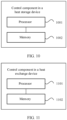
- a control component in a heat storage device includes a processor and a memory, the memory stores at least one instruction, and the instruction is loaded and executed by the processor to implement an operation performed by the control method according to the fourth aspect.
- a control component in a heat exchange device includes a processor and a memory, the memory stores at least one instruction, and the instruction is loaded and executed by the processor to implement an operation performed by the control method according to the fifth aspect.
- the heat exchange liquid stored in the heat exchange pipe in the heat storage device is used to perform heat exchange with the heat exchange requirement component, and the heat exchange liquid may absorb heat generated by the heat exchange requirement component, to cool the heat exchange requirement component.
- a path for circulating heat exchange liquid may be formed between the third connection port, the fourth connection port, the heat exchange pipe, and the liquid storage component, the power pump, the first connection port and the second connection port of the first connection apparatus that are in the heat exchange device in this application.
- the power pump in the heat exchange device may enable the heat exchange liquid in the heat storage device and the heat exchange liquid in the liquid storage component circulate in the path, so that the heat exchange liquid in the heat storage device is at an appropriate temperature, so as to continue performing heat exchange with the heat exchange requirement component when required.
- Heat exchange device 20. Heat storage device; 30. External liquid storage component; 101. First connection component; 102. Power pump; 103. First control component; 104. Liquid storage component; 105. Travel component; 106. Temperature adjustment component; 201. Third connection component; 202. Heat exchange pipe; 203. Second control component; 1011. First connection port; 1012. Second connection port; 1013. First connection detection circuit; 2011. Third connection port; 2012. Second connection port; and 2013. Second connection detection circuit.
- Embodiments of this application provide a heat management system.
- the heat management system includes a heat storage device and a heat exchange device.
- the heat storage device may be deployed in a device such as a movable charging vehicle, a charging pile, or an electric vehicle.
- the heat storage device is configured to absorb heat generated by a heat exchange requirement component in a device in which the heat storage device is located, and is further configured to provide heat for the heat exchange requirement component.
- the heat exchange device may be deployed independently, for example, deployed in a form of a movable heat exchange vehicle or a fixed heat exchange base station.
- the heat exchange device may perform heat exchange with the heat storage device, so as to implement heat management on the heat storage device.
- the heat exchange device When the heat storage device is deployed in a movable device, the heat exchange device may be deployed in a form of a movable heat exchange device, or may be deployed in a form of a fixed heat exchange device.
- a carrier of the heat storage device when the heat storage device has a heat exchange requirement, a carrier of the heat storage device may be moved to the movable heat exchange device, or a carrier of the heat storage device and the movable heat exchange device are moved to a same place, so as to complete heat exchange with the heat exchange device.
- a carrier of the heat storage device When the heat exchange device is deployed in the form of the fixed heat exchange device, when the heat storage device has a heat exchange requirement, a carrier of the heat storage device may be moved to the fixed heat exchange device, so as to complete heat exchange with the heat exchange device.
- the heat exchange device When the heat storage device is deployed in a non-movable device, the heat exchange device may be deployed in a form of a movable heat exchange device. When the heat storage device needs to exchange heat, the movable heat exchange device may move to the heat storage device to perform heat exchange with the heat storage device.
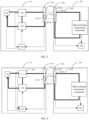
- FIG. 1 shows a heat management system provided in an embodiment of this application.
- the heat management system includes a heat exchange device 10 and a heat storage device 20.
- the heat exchange device 10 includes a first connection component 101, a first control component 103, a liquid storage component 104, and a power pump 102.
- the heat storage device 20 includes a second connection component 201 and a heat exchange pipe 202.
- the first connection component 101 includes a first connection port 1011 and a second connection port 1012.
- the second connection component 201 includes a third connection port 2011 and a fourth connection port 2012.
- the first connection port 1011 and the second connection port 1012 are configured to connect to the third connection port 2011 and the fourth connection port 2012 respectively.
- the second connection port 1012 is connected to a first port of the power pump 102
- the first connection port 1011 is connected to a first port of the liquid storage component 104
- a second port of the liquid storage component 104 is connected to a second port of the power pump 102
- two ports of the heat exchange pipe 202 are connected to the third connection port 2011 and the fourth connection port 2012 respectively.
- the heat exchange pipe 202 is configured to store heat exchange liquid, and the heat exchange liquid stored in the heat exchange pipe 202 is used to perform heat exchange with a heat exchange requirement component.
- the first control component 103 is configured to control the power pump 102 to be enabled or disabled.
- the first connection port 1011 may be a male end or a female end of a quick-connect plug with two ends open and closed, and a connection port that is of the second connection component 201 and that is configured to connect to the first connection port 1011 is a female end or a male end of a quick-connect plug with two ends open and closed that matches the first connection port 1011.
- the second connection port 1012 may also be a male end or a female end of a quick-connect plug with two ends open and closed, and a connection port that is of the second connection component 201 and that is configured to connect to the second connection port 1012 is a female end or a male end of a quick-connect plug with two ends open and closed that matches the second connection port 1012.
- the liquid storage component 104 may be a liquid storage tank, a liquid storage box, or the like, and the power pump 102 may be a circulating water pump.
- the heat exchange pipe 202 may be a metal cooling plate, a metal cooling pipe, a plastic cooling pipe, or the like.
- the heat exchange liquid may be liquid, for example, water, mixed liquor of water, and ethylene glycol, or a phase change material, that absorbs heat, stores heat, discharges heat, and balances temperatures of heat exchange requirement components.
- the heat exchange requirement component may include various components that need dissipate heat or heat in a carrier of the heat storage device, such as an energy storage component, an electric drive component, and an inverter component.
- the energy storage component may be a lithium-ion battery, a fuel cell, a power generation device, or the like.
- the electric driver component may be a permanent-magnet synchronous motor, a belt-driven starter generator (Belt-Driven Starter Generator, BSG), or the like.
- the inverter component may be a direct-current-alternating-current inverter, an alternating-current-direct-current inverter, or an inverter integrated with a plurality of inverters.
- the second connection port 1012 may be connected to the first port of the power pump 102 through a pipe
- the first connection port 1012 may be connected to the first port of the liquid storage component 104 through a pipe
- the second port of the liquid storage component 104 may be connected to the second port of the power pump 102 through a pipe.
- the pipe herein used to connect the ports may be the same as the heat exchange pipe, namely, may be a metal cooling plate, a metal cooling pipe, a plastic cooling pipe, or the like.
- each heat exchange requirement component may be provided with a heat exchange path used for heat exchange, and the heat exchange path passes through the heat exchange requirement component.
- the heat exchange paths in the heat exchange requirement components may be connected to each other through the heat exchange pipe 202, or the heat exchange pipe 202 may pass through the heat exchange paths.
- One end of the heat exchange pipe 202 is connected to the third connection port 2011, and the other end is connected to the fourth connection port 2012.
- the first connection port 1011, the second connection port 1012, the third connection port 2011, and the fourth connection port 2012 are in a disabled state.
- the first connection port 1011 and the second connection port 1012 are connected to the third connection port 2011 and the fourth connection port 2012 respectively, and the first connection port 1011, the second connection port 1012, the third connection port 2011, and the fourth connection port 2012 are switched to an enabled state after being connected.
- a loop for circulating heat exchange liquid is formed between the liquid storage component 104, the power pump 102, the first connection port 1011, the second connection port 1012, the third connection port 2011, the fourth connection port 2012, and the heat exchange pipe 202.
- the first control component 103 may enable the power pump 102, control the power pump 102 to import the heat exchange liquid in the second heat exchange pipe 202 into the liquid storage component 104 in the heat exchange device 10, and export heat exchange liquid in the liquid storage component 104 to the second heat exchange pipe 202 in the heat storage device 20.
- Heat exchange duration may be set based on power of the power pump and mass of heat exchange liquid in the heat storage device 20.
- a first connection detection circuit 1013 may be disposed in the first connection component 101, and a second connection detection circuit 2013 may be disposed in the second connection component 201.
- the first connection detection circuit 1013 includes a first end of a first communication connector and a first end of a second communication connector, and the two ends correspond to the first connection port 1011 and the second connection port 1012 respectively.
- the second connection detection circuit 2013 includes a second end of the first communication connector and a second end of the second communication connector, and the two ends correspond to the third connection port 2011 and the fourth connection port 2012 respectively.
- a first end and a second end of each communication connector are a male end and a female end respectively, and the two ends may be connected in a matched manner.
- first connection port 1011 and the third connection port 2011 or the fourth connection port 2012 that is configured to connect to the first connection port 1011 are in a connected state, it needs to be ensured that ends of communication connectors corresponding to the two connection ports are connected to each other and are in a connected state.
- first connection port 1011 and the third connection port 2011 or the fourth connection port 2012 that is configured to connect to the first connection port are in a disconnected state, it needs to be ensured that the ends of the communication connectors corresponding to the two connection ports are disconnected from each other and are in a disconnected state.
- the first connection detection circuit 1013 and the second connection detection circuit 2013 form a complete interlock circuit by using the first communication connector and the second communication connector.
- the first connection detection circuit 1013 sends a low level signal to the first control component 103.
- the first connection detection circuit 1013 sends a high level signal to the first control component 103. If the first control component 103 receives the low level signal at a previous moment, and receives the high level signal at a next moment, it may be determined that connection statuses of the first connection port 1011 and the second connection port 1012 both change from disconnected to connected.
- the heat storage device 20 may further include a second control component 203.
- the second control component 203 may monitor, in real time by using a temperature sensor in each heat exchange requirement component, a temperature of a corresponding heat exchange requirement component. In a heat exchange process, when the second control component 203 detects that each heat exchange requirement component reaches a required temperature, the second control component 203 may send a heat exchange stop request to the first control component 103.
- communications modules such as a wireless transmission communications module, a 4th generation mobile communication technology (the 4th generation mobile communication technology, 4G) communications module, and a 5th generation mobile communication technology (the 5th generation mobile communication technology, 5G) communications module may be disposed on the first control component 103 and the second control component 203.
- the second control component 203 may send the heat exchange stop request to the first control component 103 by using the communications module.
- forms of the heat exchange stop request may also be different.
- first control component 103 and the second control component 203 may further communicate with each other in a wired manner.
- the first control component 103 may be connected to a communication signal cable and led out from the first connection component 101.
- a first end of a low-voltage communication connector may be disposed at an end at which the communication signal cable is led out.
- the second control component 203 may also be connected to the communication signal cable and led out from the second connection component 201.
- a second end of the low-voltage communication connector may be disposed at the end at which the communication signal cable is led out, and the first end and the second end may be a male end and a female end respectively, and may be connected in a matched manner.
- the first end and the second end may be connected in a matched manner.
- the second control component 203 may send the heat exchange stop request to the first control component 103 through the communication signal cable.
- the heat exchange stop request may be in a plurality of forms, for example, in a CAN signal form.
- a temperature adjustment component 106 may be disposed in the heat exchange device 10.
- the temperature adjustment component 106 may include a compressor, an evaporator, a heat exchanger, a condenser, a fan, a heat dissipation fan, a positive temperature coefficient (Positive Temperature Coefficient, PTC) heater, and the like.
- a first port and a second port of the temperature adjustment component 106 are connected to a third port of the liquid storage component 104 and a third port of the power pump 102 respectively.
- the power pump 102 may have three ports, which are connected to the temperature adjustment component 106, the liquid storage component 104, and the first connection port 1011 respectively.
- a temperature sensor may be disposed in the liquid storage component 104, and the temperature sensor may send detected temperature information to the first control component 103.
- the first control component 103 controls the temperature adjustment component 106 to start a cooling mode, and controls the power pump 102 to be enabled to enter a first working state.
- a first port is disabled, and a second port and the third port are enabled, so that the heat exchange liquid in the liquid storage component 104 circulates in the liquid storage component 104, the power pump 102, and the temperature adjustment component 106.
- the first control component 103 controls the temperature adjustment component (106) and the power pump 102 to be disabled.
- the target temperature range may be set according to an actual requirement, for example, from 15 degrees Celsius to 35 degrees Celsius.
- the first control component 103 controls the temperature adjustment component 106 to start a heating mode, and controls the power pump 102 to be enabled to enter the first working state, so that the heat exchange liquid in the liquid storage component 104 circulates in the liquid storage component 104, the power pump 102, and the temperature adjustment component 106; and when it is detected that the temperature of the heat exchange liquid in the liquid storage component 104 is within the target temperature range again, controls the temperature adjustment component 106 and the power pump 102 to be disabled.
- the two types of heat exchange liquid may be stored independently.
- the liquid storage component 104 may be disposed in a layered structure.
- an upper layer of the liquid storage component 104 is used to store the heat exchange liquid from the heat storage device 20, and a lower layer is used to store heat exchange liquid for importing into the heat storage device 20.
- an exhaust hole may be disposed on the top of the upper layer of the liquid storage component 104.
- a second port and the third port of the liquid storage component 104 may be disposed at the upper layer of the liquid storage component 104, and a first port may be disposed at the lower layer of the liquid storage component 104.
- the first control component 103 may enable the power pump 102 to enter a second working state.
- the third port is disabled, and the first port and the second port are enabled, so that the heat exchange liquid in the heat storage device 20 is imported into the upper layer of the liquid storage component 104 in the heat exchange device 10, and the heat exchange liquid in the lower layer of the liquid storage component 104 is imported into the second heat exchange pipe 202 in the heat storage device 20.
- temperature sensors may be disposed at both the upper layer and the lower layer of the liquid storage component 104 in this case.
- the temperature sensors send detected temperature information of heat exchange liquid at the upper layer and the lower layer to the first control component 103.
- the first control component 103 may control the power pump 102 to be enabled to enter the first working state, so that the heat exchange liquid at the upper layer of the liquid storage component 104 is exported to the temperature adjustment component 106 for temperature adjustment, and then is imported into the lower layer of the liquid storage component 104. Then the power pump is switched to a third working state.
- the heat exchange liquid at the lower layer is imported into the upper layer, to circulate the heat exchange liquid between the upper layer and the lower layer. Until it is detected that temperatures of the heat exchange liquid at the two layers are within the target temperature range, the first control component 103 controls the power pump 102 and the temperature adjustment component 106 to be disabled.
- a temperature adjustment power pump 107 may be disposed in the heat exchange device 10.
- the power pump 102 is configured to perform heat exchange between the heat exchange device 10 and the heat storage device 20
- the temperature adjustment power pump 107 is configured to provide power when temperature adjustment is performed on the heat exchange liquid in the liquid storage component 104.
- a first port of the temperature adjustment power pump 107 is connected to the temperature adjustment component 106, and a second port of the temperature adjustment power pump 107 is connected to the liquid storage component 104.
- the first control component 103 starts the heating mode or the cooling mode of the temperature adjustment component 106, and enables the temperature adjustment power pump 107, so that the heat exchange liquid in the liquid storage component 104 circulates between the liquid storage component 104, the temperature adjustment component 106, and the temperature adjustment power pump 107, thereby achieving a purpose of temperature adjustment.
- the heat exchange device 10 may further include a travel component 105, for example, an auto-driving chassis, or an AGV.
- the heat exchange device may be a movable heat exchange device, for example, a movable heat exchange vehicle.
- the second control component 203 in the heat storage device 20 may send a heat exchange request to the first control component 103 when it is detected that the temperature of the heat exchange requirement component is not within a normal working temperature range.
- the heat exchange request carries position information of the heat storage device 20.
- the second control component 203 may send the heat exchange request to a management end, and the management end obtains position information of each heat exchange device, and selects a heat exchange device 10 that is in an idle state and closest to the heat storage device 20 as a heat exchange device for performing heat exchange with the heat storage device 20.
- the idle state herein indicates that the heat exchange device is executing a heat exchange task.
- the management end may return communication information of the selected heat exchange device 10 to the heat storage device 20, so that a communication connection can be established between the second control component 203 in the heat storage device 20 and the first control component 103 in the heat exchange device 10.
- the management end forwards the heat exchange request to the selected heat exchange device 10, and the first control component 103 in the heat exchange device 10 receives the heat exchange request.
- the first control component 103 may send the position information to the travel component 105, and the travel component 105 travels, based on a navigation apparatus, the heat exchange device 10 to a position corresponding to the position information.
- the navigation apparatus is, for example, a GNSS (Global Navigation Satellite System, global navigation satellite apparatus).
- the first control component 103 sends a heat exchange connection request.
- the heat exchange connection request may be a connection instruction sent to the mechanical arm.
- the mechanical arm connects the first connection port 1011 and the second connection port 1012 in the heat exchange device 10 to the third connection port 2011 and the fourth connection port 2012 in the heat storage device 20 respectively.
- the first control component 103 controls the power pump 102 to be enabled.
- the second control component 203 may send the heat exchange stop request to the first control component 103 through the established communication connection.
- the target temperature may be an optimal working temperature of each heat exchange requirement component.
- communication may also be performed herein through a communication signal cable. Details are not described herein again.
- the first control component 103 is further configured to: when receiving the heat exchange stop request, control the power pump 102 to be disabled, and send the disconnection request.
- the mechanical arm may disconnect the first port 1011, the second connection port 1012, the third connection port 2011, and the fourth connection port 2012.
- the heat storage device may be deployed in a movable charging vehicle, and the heat exchange requirement component belongs to the movable charging vehicle.
- an electric vehicle may send a charging request to a management end.
- the management end selects, based on position information of the electric vehicle carried in the charging request, a movable charging vehicle closest to the electric vehicle, and forwards the charging request to the movable charging vehicle.
- the second control component 203 in the movable charging vehicle receives the charging request sent by the electric vehicle, obtains the position information and charging requirement information that are of the electric vehicle and that are carried in the charging request, and calculates, based on the charging requirement information, an estimated temperature of the heat exchange requirement component after discharging ends.
- the charging requirement information carried in the charging request may include at least one of required power and required charging time. If the estimated temperature of the heat exchange requirement component is not higher than an upper limit of a normal working temperature, the second control component controls the movable charging vehicle to travel to a position corresponding to the position information to perform charging processing.
- An equation for calculating the estimated temperature of the heat exchange requirement component may be as follows:
- n is a quantity of heat exchange requirement components
- P i is power of an i th heat exchange requirement component
- ⁇ i is efficiency of the power of the i th heat exchange requirement component
- C i is a specific heat capacity of the i th heat exchange requirement component
- M i is mass of the i th heat exchange requirement component
- T i is a current temperature of the i th heat exchange requirement component, is a specific heat capacity of the heat exchange liquid in the heat storage device 20, is mass of the heat exchange liquid in the heat storage device 20, is an estimated temperature of the heat exchange liquid in the heat storage device 20 when discharging ends, T i is a current temperature of the heat exchange liquid in the heat storage device 20, ⁇ T 1 is a constant, and is required charging time. If the charging requirement information does not include the required charging time, the required charging time may be calculated by using charged electricity and the power of the heat exchange requirement component.
- the electric vehicle may further reserve charging time, that is, the charging request further carries a required charging start moment of the electric vehicle.
- the second control component 203 can calculate, based on the required charging time and heat exchange power of the heat exchange device 10 in a case in which the temperature of the heat exchange requirement component is the upper limit of the normal working temperature when discharging ends, an estimated initial temperature required for heat exchange liquid stored in the heat exchange pipe 202 and estimated heat exchange duration required for adjusting a temperature of the heat exchange liquid stored in the heat exchange pipe 202 to the estimated initial temperature. Equations for calculating the estimated initial temperature and the estimated heat exchange duration required by the heat exchange liquid may be as follows:
- ⁇ T 2 is a constant, is the estimated initial temperature required for the heat exchange liquid stored in the heat exchange pipe 202 when the temperature of the heat exchange requirement component is the upper limit of the normal working temperature when discharging ends, is the estimated heat exchange duration required for adjusting the temperature of the heat exchange liquid stored in the heat exchange pipe 202 to the estimated initial temperature, is the upper limit of the normal working temperature of the heat exchange requirement component, is the upper limit of the normal working temperature of the heat exchange liquid in the heat storage device 20 when discharging ends.
- the second control component 203 calculates, based on the position information of the electric vehicle, estimated travel duration in which the movable charging vehicle travels to the electric vehicle, and calculates a time difference between a current moment and the required charging start moment.
- the second control component 203 controls the movable charging vehicle to travel to a target heat exchange position, and sends a heat exchange connection request.
- the heat exchange connection request may be sent to a management platform, and the management platform may prompt a worker to perform a heat exchange connection.
- the worker may connect the third connection port 2011 and the fourth connection port 2012 in the heat storage device 20 on the movable charging vehicle to the first connection port 1011 and the second connection port 1012 in the heat exchange device 10.
- the first control component 103 controls the power pump 102 to be enabled to perform heat exchange.
- the second control component After it is detected that the connection statuses of the third connection port 2011 and the fourth connection port 2012 are both switched from disconnected to connected, when it is detected that the temperature of the heat exchange liquid stored in the heat exchange pipe 202 reaches the estimated initial temperature, the second control component sends the heat exchange stop request to the first control component 103, and sends the heat exchange disconnection request.
- the heat exchange connection request may also be sent to the management platform, and the management platform may prompt the worker to disconnect the heat exchange connection. The worker may disconnect the third connection port 2011 and the fourth connection port 2012 in the heat storage device 20 on the movable charging vehicle from the first connection port 1011 and the second connection port 1012 in the heat exchange device 10.
- the first control component 103 controls the power pump 102 to be enabled; and when receiving the heat exchange stop request, controls the power pump 102 to be disabled.
- the second control component 203 controls the movable charging vehicle to travel to the position corresponding to the position information of the electric vehicle.
- a heat exchange management system herein may further include an external liquid storage component 30, and the external liquid storage component 30 stores heat exchange liquid of an appropriate temperature, for example, a heat exchange liquid of 30 degrees Celsius.
- a first port and a second port of the external liquid storage component 30 are configured to connect respectively to the third connection port 2011 and the fourth connection port 2012 that are in the heat storage device 20.
- the first port and the second port of the liquid storage component 30 may be the same as the first connection port 1011 and the second connection port 1012 in the heat exchange device 10.
- the external liquid storage component connection request may also be sent to the management platform, and the management platform may prompt the worker to perform connection processing on the external liquid storage component.
- the worker may enable the first port and the second port of the external liquid storage component 30 to connect respectively to the third connection port 2011 and the fourth connection port 2012 that are in the heat storage device 20.
- the second control component 203 controls the movable charging vehicle to travel to the position corresponding to the position information of the electric vehicle, and performs charging processing on the electric vehicle.
- mass of the heat exchange liquid in the external liquid storage component that needs to be carried may be calculated.
- An equation for calculating the mass of the heat exchange liquid in the external liquid storage component may be as follows:
- the external liquid storage component connection request may carry the mass of the heat exchange liquid in the external liquid storage component, and the worker may select an external liquid storage component that stores the mass to connect to the heat storage device 20.
- the heat exchange liquid in the heat storage device 20 may be kept above the lower limit of the normal working temperature, for example, kept above 15 degrees Celsius.
- heat exchange may be performed with the heat exchange device 10. In this way, it can be ensured that the heat exchange requirement component can be in the normal working temperature in cold weather, so as to provide a more efficient charging service.
- the heat exchange device 10 may include a plurality of first connection components, and each connection component corresponds to one power pump. After one heat storage device is connected to a connection port of one first connection component, the first control component 103 may enable a corresponding power pump to perform a heat exchange task. In this way, one heat exchange device 10 may perform heat exchange on a plurality of heat storage devices at the same time, thereby improving heat exchange efficiency.
- An embodiment of this application further provides a heat management method.
- the heat management method may be applied to the heat management system in which the heat exchange device 10 includes the travel component 105 and the heat storage device 20 includes a second control component 203. Refer to FIG. 8 .
- a procedure of the heat management method may include the following steps:
- Step 801 The second control component 203 sends a heat exchange request to a first control component 103 when it is detected that a temperature of a heat exchange requirement component is not within a normal working temperature range.
- the heat exchange request carries position information of the heat storage device 20.
- Step 802 The first control component 103 controls the travel component 105 to travel to a position corresponding to the position information.
- Step 803 When it is detected that the travel component 105 travels to the position corresponding to the position information, the first control component 103 sends a heat exchange connection request.
- Step 804 When it is detected that connection statuses of a first connection port 1011 and a second connection port 1012 are switched from disconnected to connected, the first control component 103 controls a power pump 102 to be enabled.
- Step 805 After it is detected that connection statuses of a third connection port 2011 and a fourth connection port 2012 are both switched from disconnected to connected, when it is detected that the temperature of the heat exchange requirement component is a target temperature, the second control component 203 sends a heat exchange stop request to the first control component 103.
- Step 806 When receiving the heat exchange stop request, the first control component 103 controls the power pump 102 to be disabled.
- step 801 to step 805 operations performed by the first control component 103 and the second control component 203 in the foregoing step 801 to step 805 are the same as operations performed by the first control component 103 and the second control component 203 when the heat exchange device 10 in the embodiment of the heat management system has the travel component. Details are not described herein again.
- An embodiment of this application further provides still another heat management method.
- the heat management method may be applied to a heat management system in which the heat storage device 20 includes the second control component 203, and the heat storage device 20 is deployed in a movable charging vehicle.
- a procedure of the heat management method may include the following steps:
- Step 901 The second control component 203 receives a charging request sent by an electric vehicle.
- Step 902 The second control component 203 obtains position information, required power, and required charging time that are of the electric vehicle and that are carried in the charging request, and calculates, based on the required power and the required charging time, an estimated temperature of a heat exchange requirement component after discharging ends.
- Step 903 The second control component 203 determines whether the estimated temperature of the heat exchange requirement component is higher than an upper limit of a normal working temperature.
- Step 904 If determining that the estimated temperature of the heat exchange requirement component is not higher than the upper limit of the normal working temperature, the second control component 203 controls the movable charging vehicle to travel to a position corresponding to the position information to perform charging processing.
- Step 905 if determining that the estimated temperature of the heat exchange requirement component is higher than the upper limit of the normal working temperature, the second control component 203 calculates, based on the required charging time and heat exchange power of the heat exchange device 10 in a case in which a temperature of the heat exchange requirement component is the upper limit of the normal working temperature when discharging ends, an estimated initial temperature required by heat exchange liquid stored in a heat exchange pipe 202 and estimated heat exchange duration required for adjusting a temperature of the heat exchange liquid stored in the heat exchange pipe 202 to the estimated initial temperature; calculates, based on the position information of the electric vehicle, estimated travel duration for the movable charging vehicle to travel to the electric vehicle; and calculates a time difference between a current moment and a required charging start moment.
- Step 906 The second control component 203 determines whether a sum of the estimated heat exchange duration and the estimated travel duration is greater than the time difference.
- Step 907 If determining that the sum of the estimated heat exchange duration and the estimated travel duration is greater than the time difference, the second control component 203 sends an external liquid storage component connection request, and when it is detected that connection statuses of a third connection port 2011 and a fourth connection port 2012 are both switched from disconnected to connected, controls the movable charging vehicle to travel to the position corresponding to the position information to perform charging processing.
- Step 908 If determining that the sum of the estimated heat exchange duration and the estimated travel duration is not greater than the time difference, the second control component 203 controls the movable charging vehicle to travel to a target heat exchange position, and sends a heat exchange connection request.
- Step 909 After it is detected that the connection statuses of the third connection port 2011 and the fourth connection port 2012 are both switched from disconnected to connected, when it is detected that the temperature of the heat exchange liquid stored in the heat exchange pipe 202 reaches the estimated initial temperature, the second control component 203 sends a heat exchange stop request to the first control component 103, and sends a heat exchange disconnection request; and when it is detected that the connection statuses of the third connection port 2011 and the fourth connection port 2012 are both switched from connected to disconnected, controls the movable charging vehicle to travel to a position corresponding to the position information to perform charging processing.
- Step 910 When it is detected that connection statuses of a first connection port 1011 and a second connection port 1012 are switched from disconnected to connected, a first control component 103 controls a power pump 102 to be enabled; and when receiving the heat exchange stop request, controls the power pump 102 to be disabled.
- step 901 to step 910 operations performed by the first control component 103 and the second control component 203 in the foregoing step 901 to step 910 are the same as operations performed by the first control component 103 and the second control component 203 when the heat storage device 20 in the embodiment of the heat management system is deployed on the movable charging vehicle. Details are not described herein again.
- FIG. 10 is a schematic diagram of a structure of a control component in a heat storage device according to an embodiment of this application.
- the control component in the heat storage device may be the second control component in the foregoing heat storage device.
- the control component in the heat storage device may vary greatly due to different configurations or performance, and may include one or more processors (central processing units, CPU) 1001 and one or more memories 1002.
- the memory 1002 stores at least one instruction, and the at least one instruction is loaded and executed by the processor 1001 to implement the control method for the heat storage device.
- FIG. 11 is a schematic diagram of a structure of a control component in a heat exchange device according to an embodiment of this application.
- the control component in the heat exchange device may be the first control component in the foregoing heat exchange device.
- the control component in the heat exchange device may vary greatly due to different configurations or performance, and may include one or more processors (central processing units, CPU) 1101 and one or more memories 1102.
- the memory 1102 stores at least one instruction, and the at least one instruction is loaded and executed by the processor 1101 to implement the control method for the heat exchange device.
Landscapes
- Engineering & Computer Science (AREA)
- Manufacturing & Machinery (AREA)
- Chemical & Material Sciences (AREA)
- Chemical Kinetics & Catalysis (AREA)
- Electrochemistry (AREA)
- General Chemical & Material Sciences (AREA)
- Mechanical Engineering (AREA)
- Transportation (AREA)
- Power Engineering (AREA)
- Automation & Control Theory (AREA)
- Microelectronics & Electronic Packaging (AREA)
- Life Sciences & Earth Sciences (AREA)
- Sustainable Development (AREA)
- Sustainable Energy (AREA)
- Physics & Mathematics (AREA)
- Thermal Sciences (AREA)
- General Engineering & Computer Science (AREA)
- Electric Propulsion And Braking For Vehicles (AREA)
- Charge And Discharge Circuits For Batteries Or The Like (AREA)
Abstract
Description
- This application relates to the field of new energy vehicle technologies, and in particular, to a heat storage device, a heat exchange device, a control method, a control component, and a heat management system.
- As electric vehicles continuously develop, charging devices such as a movable charging vehicle and a charging pile accordingly emerge. A heat dissipation system is usually disposed in the charging device to dissipate heat for the charging device during charging and discharging of the charging device.
- Currently, an air-cooled heat dissipation system is usually used to dissipate heat for the charging device. The air-cooled heat dissipation system mainly includes a heat dissipation hole, a heat dissipation fin, a fan, and the like. When heat needs to be dissipated, the fan is started. The heat generated inside the charging device is dissipated by using air generated by the fan through the heat dissipation hole and the heat dissipation fin.
- The charging device generates a large amount of heat in an application scenario of high-power charging and discharging such as fast charging, but the air-cooled heat dissipation system has low heat dissipation efficiency, and therefore cannot effectively dissipate the heat for the charging device in the application scenario.
- Embodiments of this application provide a heat storage device, a heat exchange device, a control method, a control component, and a heat management system, to resolve a problem in the related technology that an air-cooled system cannot meet a heat dissipation requirement during high-power charging and discharging of a charging device.
- According to a first aspect, a heat management system is provided. The heat management system includes a
heat exchange device 10 and aheat storage device 20. Theheat exchange device 10 includes afirst connection component 101, apower pump 102, afirst control component 103, and aliquid storage component 104. Theheat storage device 20 includes asecond connection component 201 and aheat exchange pipe 202. Thefirst connection component 101 includes afirst connection port 1011 and asecond connection port 1012. Thesecond connection component 201 includes athird connection port 2011 and afourth connection port 2012. Thefirst connection port 1011 and thesecond connection port 1012 are configured to connect to thethird connection port 2011 and thefourth connection port 2012 respectively. Thesecond connection port 1012 is connected to a first port of thepower pump 102, thefirst connection port 1011 is connected to a first port of theliquid storage component 104, a second port of theliquid storage component 104 is connected to a second port of thepower pump 102, and two ports of theheat exchange pipe 202 are connected to thethird connection port 2011 and thefourth connection port 2012 respectively. Theheat exchange pipe 202 is configured to store heat exchange liquid, and the heat exchange liquid stored in theheat exchange pipe 202 is used to perform heat exchange with a heat exchange requirement component. Thefirst control component 103 is configured to control thepower pump 102 to be enabled or disabled. - In the solution shown in this embodiment of this application, the
first connection port 1011 may be a male end or a female end of a quick-connect plug with two ends open and closed, and a connection port that is of thesecond connection component 201 and that is configured to connect to thefirst connection port 1011 is a female end or a male end of a quick-connect plug with two ends open and closed that matches thefirst connection port 1011. Likewise, thesecond connection port 1012 may also be a male end or a female end of a quick-connect plug with two ends open and closed, and a connection port that is of thesecond connection component 201 and that is configured to connect to thesecond connection port 1012 is a female end or a male end of a quick-connect plug with two ends open and closed that matches thesecond connection port 1012. Theliquid storage component 104 may be a liquid storage tank, a liquid storage box, or the like, and thepower pump 102 may be a circulating water pump. Theheat exchange pipe 202 may be a metal cooling plate, a metal cooling pipe, a plastic cooling pipe, or the like. The heat exchange liquid may be liquid, for example, water, mixed liquor of water, and ethylene glycol, or a phase change material, that absorbs heat, stores heat, discharges heat, and balances temperatures of heat exchange requirement components. The heat exchange requirement component may include various components that need dissipate heat or heat in a carrier of the heat storage device, such as an energy storage component, an electric drive component, and an inverter component. The energy storage component may be a lithium-ion battery, a fuel cell, a power generation device, or the like. The electric driver component may be a permanent-magnet synchronous motor, a belt-driven starter generator (Belt-Driven Starter Generator, BSG), or the like. The inverter component may be a direct-current-alternating-current inverter, an alternating-current-direct-current inverter, or an inverter integrated with a plurality of inverters. - A loop for circulating heat exchange liquid may be formed between the
liquid storage component 104, thepower pump 102, thefirst connection port 1011, thesecond connection port 1012, thethird connection port 2011, thefourth connection port 2012, and theheat exchange pipe 202. Thepower pump 102 in the heat exchange device may enable the heat exchange liquid in theheat exchange pipe 202 and heat exchange liquid in the liquid storage component circulate in the loop, so that heat exchange liquid in the heat storage device is at an appropriate temperature, and the heat exchange liquid in theheat exchange pipe 202 continues performing heat exchange with the heat exchange requirement component when required. - In a possible implementation, the
heat exchange device 10 further includes atravel component 105, and theheat storage device 20 further includes asecond control component 203. Thefirst connection component 101, thefirst control component 103, theliquid storage component 104, and thepower pump 102 are disposed on thetravel component 105. Thesecond control component 203 is configured to send a heat exchange request to thefirst control component 103 when it is detected that a temperature of the heat exchange requirement component is not within a normal working temperature range, where the heat exchange request carries position information of theheat storage device 20. Thefirst control component 103 is configured to control thetravel component 105 to travel to a position corresponding to the position information. - In the solution shown in this embodiment of this application, the
travel component 105 may be an auto-driving chassis, an AGV, or the like. The heat storage device may send the heat exchange request by using thesecond control component 203 when heat exchange is required. After receiving the heat exchange request, theheat exchange device 10 may travel to theheat storage device 20 by using thetravel component 105, to perform heat exchange with theheat storage device 20. - In a possible implementation, the
first control component 103 is further configured to: send a heat exchange connection request when it is detected that thetravel component 105 travels to the position corresponding to the position information, and when it is detected that connection statuses of thefirst connection port 1011 and thesecond connection port 1012 are switched from disconnected to connected, control thepower pump 102 to be enabled. Thesecond control component 203 is further configured to: after it is detected that connection statuses of thethird connection port 2011 and thefourth connection port 2012 are both switched from disconnected to connected, and when it is detected that the temperature of the heat exchange requirement component is a first temperature, send a heat exchange stop request to thefirst control component 103. Thefirst control component 103 is further configured to: when receiving the heat exchange stop request, control thepower pump 102 to be disabled. - In the solution shown in this embodiment of this application, when it is detected that the connection statuses of the
first connection port 1011 and thesecond connection port 1012 are switched from disconnected to connected, thefirst control component 103 may control thepower pump 102 to be enabled, where thepower pump 102 may exchange the heat exchange liquid in the heat exchange pipe with the heat exchange liquid in the liquid storage component; and after heat exchange is completed, control thepower pump 102 to be disabled. - In a possible implementation, the
heat storage device 20 is deployed in a movable charging vehicle, the heat exchange requirement component belongs to a movable charging vehicle, and theheat storage device 20 further includes asecond control component 203. Thesecond control component 203 is configured to: receive a charging request sent by an electric vehicle; obtain position information and charging requirement information of the electric vehicle that are carried in the charging request, where the charging requirement information includes at least one of required power and required charging time; calculate, based on the charging requirement information, an estimated temperature of the heat exchange requirement component after discharging ends; and if the estimated temperature of the heat exchange requirement component is not higher than an upper limit of a normal working temperature, control the movable charging vehicle to travel to a position corresponding to the position information to perform charging processing. - In the solution shown in this embodiment of this application, the heat storage device can be deployed in the movable charging vehicle. When charging is required, the electric vehicle can send the charging request to the movable charging vehicle. The
second control component 203 receives the charging request sent by the electric vehicle, calculates, based on the charging requirement information, the estimated temperature of the heat exchange requirement component after discharging ends, and if the estimated temperature of the heat exchange demand component is not higher than the upper limit of the normal working temperature, controls the movable charging vehicle to travel to the position corresponding to the position information to perform charging processing. In this way, in a process in which the movable charging vehicle charges the electric vehicle, the temperature of the heat exchange requirement component (such as a battery) of the movable charging vehicle can be maintained at the normal working temperature, to avoid low charging efficiency caused by an excessively high temperature. - In a possible implementation, the charging request further carries a required charging start moment of the electric vehicle, the heat management system further includes an external
liquid storage component 30, a first port and a second port of the externalliquid storage component 30 are configured to connect to thethird connection port 2011 and thefourth connection port 2012 respectively, and the externalliquid storage component 30 is configured to store heat exchange liquid. Thesecond control component 203 is further configured to: if the estimated temperature of the heat exchange requirement component is higher than the upper limit of the normal working temperature, calculate, based on the charging requirement information and heat exchange power of theheat exchange device 10 in a case in which a temperature of the heat exchange requirement component is the upper limit of the normal working temperature when discharging ends, an estimated initial temperature required by the heat exchange liquid stored in theheat exchange pipe 202 and estimated heat exchange duration required for adjusting a temperature of the heat exchange liquid stored in theheat exchange pipe 202 to the estimated initial temperature; calculate, based on the position information of the electric vehicle, estimated travel duration for the movable charging vehicle to travel to the electric vehicle; calculate a time difference between a current moment and the required charging start moment; if a sum of the estimated heat exchange duration and the estimated travel duration is greater than the time difference, send an external liquid storage component connection request, and when it is detected that the connection statuses of the third connection port (2011) and the fourth connection port (2012) are both switched from disconnected to connected, control the movable charging vehicle to travel to the position corresponding to the position information to perform charging processing. - In the solution shown in this embodiment of this application, the electric vehicle can reserve charging time. If the estimated heat exchange duration required for adjusting a temperature of the heat exchange liquid to the estimated initial temperature cannot meet the reserved charging time of the electric vehicle, heat exchange cannot be performed. Instead, the external liquid storage component is externally disposed, and then the movable charging vehicle is directly controlled to travel to the position corresponding to the position information to perform charging processing. In the charging process, the heat exchange liquid in the external liquid storage component and the heat exchange liquid in the heat exchange pipe jointly cool the heat exchange requirement component by heat dissipation.
- In a possible implementation, the
second control component 203 is further configured to: if the sum of the estimated heat exchange duration and the estimated travel duration is not greater than the time difference, control the movable charging vehicle to travel to a target heat exchange position, and send a heat exchange connection request; after it is detected that the connection statuses of thethird connection port 2011 and thefourth connection port 2012 are both switched from disconnected to connected, when it is detected that the temperature of the heat exchange liquid stored in theheat exchange pipe 202 reaches the estimated initial temperature, send a heat exchange stop request to thefirst control component 103, and send a heat exchange disconnection request; and when it is detected that connection statuses of thethird connection port 2011 and thefourth connection port 2012 are both switched from connected to disconnected, control the movable charging vehicle to travel to the position corresponding to the position information to perform charging processing. Thefirst control component 103 is further configured to: when it is detected that connection statuses of thefirst connection port 1011 and thesecond connection port 1012 are switched from disconnected to connected, control thepower pump 102 to be enabled; and when receiving a heat exchange stop request, control thepower pump 102 to be disabled. - In the solution shown in this embodiment of this application, if the calculated estimated heat exchange duration required for adjusting the temperature of the heat exchange liquid to the estimated initial temperature can meet the reserved charging time of the electric vehicle, heat exchange can be performed with the heat exchange device. After heat exchange is completed, the movable charging vehicle is controlled to travel to the position corresponding to the position information to perform charging processing.
- In a possible implementation, the
first connection component 101 further includes a firstconnection detection circuit 1013, where the firstconnection detection circuit 1013 is configured to: detect the connection statuses of thefirst connection port 1011 and thesecond connection port 10 12; and send the connection statuses of thefirst connection port 1011 and thesecond connection port 1012 to thefirst control component 103. Thesecond connection component 201 further includes a secondconnection detection circuit 2013, where the secondconnection detection circuit 2013 is configured to: detect the connection statuses of thethird connection port 2011 and thefourth connection port 2012; and send the connection statuses of thethird connection port 2011 and thefourth connection port 2012 to thesecond control component 203. - In a possible implementation, the
heat exchange device 10 further includes atemperature adjustment component 106. Thetemperature adjustment component 106 is configured to adjust a temperature of the heat exchange liquid in theliquid storage component 104 to a target temperature range. - In the solution of this embodiment of this application, the
heat exchange device 10 further includes thetemperature adjustment component 106. Thetemperature adjustment component 106 may include a compressor, an evaporator, a heat exchanger, a condenser, a fan, a heat dissipation fan, a positive temperature coefficient (Positive Temperature Coefficient, PTC) heater, and the like. Thetemperature adjustment component 106 can adjust the temperature of the heat exchange liquid in theliquid storage component 104 to the target temperature range. - In a possible implementation, a first port and a second port of the
temperature adjustment component 106 are connected to a third port of theliquid storage component 104 and a third port of thepower pump 102 respectively. Thefirst control component 103 is configured to: when it is detected that the temperature of the heat exchange liquid in theliquid storage component 104 is higher than an upper limit of the target temperature range, control thetemperature adjustment component 106 to start a cooling mode, and control thepower pump 102 to be enabled, so that the heat exchange liquid in theliquid storage component 104 circulates in theliquid storage component 104, thepower pump 102, and thetemperature adjustment component 106; and when it is detected that the temperature of the heat exchange liquid in theliquid storage component 104 is within the target tempe rature range, control thetemperature adjustment component 106 and thepower pump 102 to be disabled. - In the solution shown in this embodiment of this application, the
temperature adjustment component 106 may cool the heat exchange liquid in theliquid storage component 104. - In a possible implementation, the
first control component 103 is further configured to: when it is detected that the temperature of the heat exchange liquid in theliquid storage component 104 is lower than a lower limit of the target temperature range, control thetemperature adjustment component 106 to start a heating mode, and control thepower pump 102 to be enabled, so that the heat exchange liquid in theliquid storage component 104 circulates in theliquid storage component 104, thepower pump 102, and thetemperature adjustment component 106; and when it is detected that the temperature of the heat exchange liquid in theliquid storage component 104 is within the target temperature range, control thetemperature adjustment component 106 and thepower pump 102 to be disabled. - In the solution shown in this embodiment of this application, the
temperature adjustment component 106 may heat the heat exchange liquid in theliquid storage component 104. - According to a second aspect, a heat storage device is provided. The heat storage device includes a
second connection component 201 and aheat exchange pipe 202. - The
second connection component 201 includes athird connection port 2011 and afourth connection port 2012, and thethird connection port 2011 and thefourth connection port 2012 are configured to connect respectively to afirst connection port 1011 and asecond connection port 1012 that are included in afirst connection component 101 in a heat exchange device. - Two ports of the heat exchange pipe (202) are connected to the
third connection port 2011 and thefourth connection port 2012 respectively, thefirst connection port 1012 is connected to a first port of apower pump 102 in the heat exchange device, thesecond connection port 1012 is connected to a first port of aliquid storage component 104 in the heat exchange device, and a second port of theliquid storage component 104 is connected to a second port of thepower pump 102. - The
heat exchange pipe 202 is configured to store heat exchange liquid, and the heat exchange liquid stored in theheat exchange pipe 202 is used to perform heat exchange with a heat exchange requirement component. - In a possible implementation, the heat storage device further includes a
second control component 203. - The
second control component 203 is configured to send a heat exchange request to afirst control component 103 in the heat exchange device when it is detected that a temperature of the heat exchange requirement component is not within a normal working temperature range, where the heat exchange request carries position information of theheat storage device 20. - In a possible implementation, the
second control component 203 is further configured to: after it is detected that connection statuses of thethird connection port 2011 and thefourth connection port 2012 are both switched from disconnected to connected, and when it is detected that the temperature of the heat exchange requirement component is a first temperature, send a heat exchange stop request to thefirst control component 103. - In a possible implementation, the heat storage device is deployed in a movable charging vehicle, the heat exchange requirement component belongs to the movable charging vehicle, and the heat storage device further includes a
second control component 203. - The
second control component 203 is configured to: receive a charging request sent by an electric vehicle; obtain position information and charging requirement information of the electric vehicle that are carried in the charging request, where the charging requirement information includes at least one of required power and required charging time; calculate, based on the charging requirement information, an estimated temperature of the heat exchange requirement component after discharging ends; and if the estimated temperature of the heat exchange requirement component is not higher than an upper limit of a normal working temperature, control the movable charging vehicle to travel to a position corresponding to the position information to perform charging processing. - In a possible implementation, the charging request further carries a required charging start moment of the electric vehicle.
- The second control component 203 is further configured to: if the estimated temperature of the heat exchange requirement component is higher than the upper limit of the normal working temperature, calculate, based on the charging requirement information and heat exchange power of the heat exchange device in a case in which a temperature of the heat exchange requirement component is the upper limit of the normal working temperature when discharging ends, an estimated initial temperature required by the heat exchange liquid stored in the heat exchange pipe 202 and estimated heat exchange duration required for adjusting a temperature of the heat exchange liquid stored in the heat exchange pipe 202 to the estimated initial temperature; calculate, based on the position information of the electric vehicle, estimated travel duration for the movable charging vehicle to travel to the electric vehicle; calculate a time difference between a current moment and the required charging start moment; if a sum of the estimated heat exchange duration and the estimated travel duration is greater than the time difference, send an external liquid storage component connection request, where the external liquid storage component connection request is used to request to connect to an external liquid storage component 30, a first port and a second port of the external liquid storage component 30 are configured to connect to the third connection port 2011 and the fourth connection port 2012 respectively, and the external liquid storage component 30 is configured to store heat exchange liquid; and when it is detected that connection statuses of the third connection port 2011 and the fourth connection port 2012 are both switched from disconnected to connected, control the movable charging vehicle to travel to the position corresponding to the position information to perform charging processing.
- In a possible implementation, the
second control component 203 is further configured to: if the sum of the estimated heat exchange duration and the estimated travel duration is not greater than the time difference, control the movable charging vehicle to travel to a target heat exchange position, and send a heat exchange connection request; after it is detected that the connection statuses of thethird connection port 2011 and thefourth connection port 2012 are both switched from disconnected to connected, when it is detected that the temperature of the heat exchange liquid stored in theheat exchange pipe 202 reaches the estimated initial temperature, send a heat exchange stop request to thefirst control component 103, and send a heat exchange disconnection request; and when it is detected that connection statuses of thethird connection port 2011 and thefourth connection port 2012 are both switched from connected to disconnected, control the movable charging vehicle to travel to the position corresponding to the position information to perform charging processing. - In a possible implementation, the
second connection component 201 further includes a secondconnection detection circuit 2013, and the secondconnection detection circuit 2013 is configured to detect the connection statuses of thethird connection port 2011 and thefourth connection port 2012, and send the connection statuses of thethird connection port 2011 and thefourth connection port 2012 to thesecond control component 203. - According to a third aspect, a heat exchange device is provided. The heat exchange device includes a
first connection component 101, apower pump 102, afirst control component 103 and aliquid storage component 104. - The
first connection component 101 includes afirst connection port 1011 and asecond connection port 1012, and thefirst connection port 1011 and thesecond connection port 1012 are configured to connect respectively to athird connection port 2011 and afourth connection port 2012 that are included in asecond connection component 201 in a heat storage device. - The
first connection port 1011 is connected to a first port of theliquid storage component 104, thesecond connection port 1012 is connected to a first port of thepower pump 102, thesecond connection port 1012 is connected to the first port of theliquid storage component 104, a second port of theliquid storage component 104 is connected to a second port of thepower pump 102, thefirst connection port 1012 is connected to the first port of thepower pump 102, two ports of aheat exchange pipe 202 in the heat storage device are connected to thethird connection port 2011 and thefourth connection port 2012 respectively, theliquid storage component 104 is configured to store heat storage liquid, theheat exchange pipe 202 is configured to store heat exchange liquid, and the heat exchange liquid stored in theheat exchange pipe 202 is used to perform heat exchange with a heat exchange requirement component. - The
first control component 103 is configured to control thepower pump 102 to be enabled or disabled. - In a possible implementation, the
heat exchange device 10 further includes atravel component 105. - The
first connection component 101, thefirst control component 103, theliquid storage component 104, and thepower pump 102 are disposed on thetravel component 105. - The
first control component 103 is configured to: receive a heat exchange request sent by asecond control component 203 in the heat storage device when it is detected that a temperature of the heat exchange requirement component is not within a normal working temperature range, and control thetravel component 105 to travel to a position corresponding to position information of the heat storage device carried in the heat exchange request. - In a possible implementation, the
first control component 103 is further configured to: send a heat exchange connection request when it is detected that thetravel component 105 travels to the position corresponding to the position information, and when it is detected that connection statuses of thefirst connection port 1011 and thesecond connection port 1012 are switched from disconnected to connected, control thepower pump 102 to be enabled. - The
first control component 103 is further configured to: when receiving a heat exchange stop request sent by thesecond control component 203, control thepower pump 102 to be disabled. - In a possible implementation, the
first connection component 101 further includes a firstconnection detection circuit 1013, where the firstconnection detection circuit 1013 is configured to: detect the connection statuses of thefirst connection port 1011 and thesecond connection port 10 12; and send the connection statuses of thefirst connection port 1011 and thesecond connection port 1012 to thefirst control component 103. - In a possible implementation, the heat exchange device further includes a
temperature adjustment component 106. - The
temperature adjustment component 106 is configured to adjust a temperature of the heat exchange liquid in theliquid storage component 104 to a target temperature range. - In a possible implementation, a first port and a second port of the
temperature adjustment component 106 are connected to a third port of theliquid storage component 104 and a third port of thepower pump 102 respectively. - The
first control component 103 is configured to: when it is detected that the temperature of the heat exchange liquid in theliquid storage component 104 is higher than an upper limit of the target temperature range, control thetemperature adjustment component 106 to start a cooling mode, and control thepower pump 102 to be enabled, so that the heat exchange liquid in theliquid storage component 104 circulates in theliquid storage component 104, thepower pump 102, and thetemperature adjustment component 106; and when it is detected that the temperature of the heat exchange liquid in theliquid storage component 104 is within the target temperature range, control thetemperature adjustment component 106 and thepower pump 102 to be disabled. - In a possible implementation, the
first control component 103 is further configured to: when it is detected that the temperature of the heat exchange liquid in theliquid storage component 104 is lower than a lower limit of the target temperature range, control thetemperature adjustment component 106 to start a heating mode, and control thepower pump 102 to be enabled, so that the heat exchange liquid in theliquid storage component 104 circulates in theliquid storage component 104, thepower pump 102, and thetemperature adjustment component 106; and when it is detected that the temperature of the heat exchange liquid in theliquid storage component 104 is within the target temperature range, control thetemperature adjustment component 106 and thepower pump 102 to be disabled. - According to the fourth aspect, a control method for a heat storage device is provided. The control method is applied to the heat storage device according to claim 1. The heat storage device further includes a
second control component 203, and the control method includes the following steps. - The
second control component 203 receives a charging request sent by an electric vehicle, where the charging request carries position information and charging requirement information of the electric vehicle, and the charging requirement information includes at least one of required power and required charging time. - The
second control component 203 calculates, based on the charging requirement information, an estimated temperature of the heat exchange requirement component after discharging ends, and if the estimated temperature of the heat exchange requirement component is not higher than an upper limit of a normal working temperature, controls a movable charging vehicle to travel to a position corresponding to the position information to perform charging processing. - In a possible implementation, the charging request further carries a required charging start moment of the electric vehicle, and the control method further includes the following steps.
- If the estimated temperature of the heat exchange requirement component is higher than the upper limit of the normal working temperature, the
second control component 203 calculates, based on the charging requirement information and heat exchange power of the heat exchange device in a case in which the temperature of the heat exchange requirement component is the upper limit of the normal working temperature when discharging ends, an estimated initial temperature required for heat exchange liquid stored in theheat exchange pipe 202 and estimated heat exchange duration required for adjusting a temperature of the heat exchange liquid stored in theheat exchange pipe 202 to the estimated initial temperature. - The
second control component 203 calculates, based on the position information of the electric vehicle, estimated travel duration in which the movable charging vehicle travels to the electric vehicle, and calculates a time difference between a current moment and the required charging start moment. - If a sum of the estimated heat exchange duration and the estimated travel duration is greater than the time difference, the
second control component 203 sends an external liquid storage component connection request, and when it is detected that connection statuses of thethird connection port 2011 and thefourth connection port 2012 are both switched from disconnected to connected, controls the movable charging vehicle to travel to the position corresponding to the position information to perform charging processing. - In a possible implementation, the control method further includes the following steps.
- If the sum of the estimated heat exchange duration and the estimated travel duration is not greater than the time difference, the
second control component 203 controls the movable charging vehicle to travel to a target heat exchange position, and sends a heat exchange connection request. - After it is detected that connection statuses of the
third connection port 2011 and thefourth connection port 2012 are both switched from disconnected to connected, when it is detected that the temperature of the heat exchange liquid stored in theheat exchange pipe 202 reaches the estimated initial temperature, thesecond control component 203 sends a heat exchange stop request to afirst control component 103 in a heat exchange device, and sends a heat exchange disconnection request. - When it is detected that the connection statuses of the
third connection port 2011 and thefourth connection port 2012 are both switched from connected to disconnected, thesecond control component 203 controls the movable charging vehicle to travel to the position corresponding to the position information to perform charging processing. - According to fifth aspect, a control method for a heat exchange system. The control method is applied to the heat exchange device according to claim 8. The heat exchange device further includes a
travel component 105, and the control method includes the following steps. - A
first control component 103 receives a heat exchange request sent by a heat storage device, where the heat exchange request carries position information of the heat storage device. - The
first control component 103 controls thetravel component 105 to travel to a position corresponding to the position information. - The
first control component 103 sends a heat exchange connection request when it is detected that thetravel component 105 travels to the position corresponding to the position information, and when it is detected that connection statuses of afirst connection port 1011 and asecond connection port 1012 are switched from disconnected to connected, controls thepower pump 102 to be enabled. - When receiving a heat exchange stop request sent by a
second control component 203, thefirst control component 103 controls thepower pump 102 to be disabled. - In a possible implementation, the control method further includes the following steps.
- When it is detected that a temperature of heat exchange liquid in the
liquid storage component 104 is higher than an upper limit of a target temperature range, thefirst control component 103 controls the temperature adjustment component (106) to start a cooling mode, and controls thepower pump 102 to be enabled, so that the heat exchange liquid in theliquid storage component 104 circulates in theliquid storage component 104, thepower pump 102, and thetemperature adjustment component 106. - When it is detected that the temperature of the heat exchange liquid in the
liquid storage component 104 is within the target temperature range, thefirst control component 103 controls thetemperature adjustment component 106 and thepower pump 102 to be disabled. - In a possible implementation, the control method further includes the following steps.
- When it is detected that the temperature of the heat exchange liquid in the
liquid storage component 104 is lower than a lower limit of the target temperature range, thefirst control component 103 controls thetemperature adjustment component 106 to start a heating mode, and controls thepower pump 102 to be enabled, so that the heat exchange liquid in theliquid storage component 104 circulates in theliquid storage component 104, thepower pump 102, and thetemperature adjustment component 106. - When it is detected that the temperature of the heat exchange liquid in the
liquid storage component 104 is within the target temperature range, thefirst control component 103 controls thetemperature adjustment component 106 and thepower pump 102 to be disabled. - According to a sixth aspect, a control component in a heat storage device is provided. The control component includes a processor and a memory, the memory stores at least one instruction, and the instruction is loaded and executed by the processor to implement an operation performed by the control method according to the fourth aspect.
- According to a seventh aspect, a control component in a heat exchange device is provided. The control component includes a processor and a memory, the memory stores at least one instruction, and the instruction is loaded and executed by the processor to implement an operation performed by the control method according to the fifth aspect.
- The technical solutions provided in this application include at least the following beneficial effects:
- In this application, the heat exchange liquid stored in the heat exchange pipe in the heat storage device is used to perform heat exchange with the heat exchange requirement component, and the heat exchange liquid may absorb heat generated by the heat exchange requirement component, to cool the heat exchange requirement component. In addition, a path for circulating heat exchange liquid may be formed between the third connection port, the fourth connection port, the heat exchange pipe, and the liquid storage component, the power pump, the first connection port and the second connection port of the first connection apparatus that are in the heat exchange device in this application. The power pump in the heat exchange device may enable the heat exchange liquid in the heat storage device and the heat exchange liquid in the liquid storage component circulate in the path, so that the heat exchange liquid in the heat storage device is at an appropriate temperature, so as to continue performing heat exchange with the heat exchange requirement component when required.
-
-
FIG. 1 is a schematic diagram of a heat management system according to an embodiment of this application; -
FIG. 2 is a schematic diagram of another heat management system according to an embodiment of this application; -
FIG. 3 is a schematic diagram of still another heat management system according to an embodiment of this application; -
FIG. 4 is a schematic diagram of yet another heat management system according to an embodiment of this application; -
FIG. 5 is a schematic diagram of still yet another heat management system according to an embodiment of this application; -
FIG. 6 is a schematic diagram of a further heat management system according to an embodiment of this application; -
FIG. 7 is a schematic diagram of an external liquid storage component and a heat storage device according to an embodiment of this application; -
FIG. 8 is a flowchart of a heat management method according to an embodiment of this application; -
FIG. 9A andFIG. 9B are a flowchart of another heat management method according to an embodiment of this application; -
FIG. 10 is a schematic diagram of a structure of a control component in a heat storage decide according to an embodiment of this application; and -
FIG. 11 is a schematic diagram of a structure of a control component in a heat exchange device according to an embodiment of this application. - 10. Heat exchange device; 20. Heat storage device; 30. External liquid storage component; 101. First connection component; 102. Power pump; 103. First control component; 104. Liquid storage component; 105. Travel component; 106. Temperature adjustment component; 201. Third connection component; 202. Heat exchange pipe; 203. Second control component; 1011. First connection port; 1012. Second connection port; 1013. First connection detection circuit; 2011. Third connection port; 2012. Second connection port; and 2013. Second connection detection circuit.
- To make the objectives, technical solutions, and advantages of this application clearer, the following further describes implementations of this application in detail with reference to the accompanying drawings.
- Embodiments of this application provide a heat management system. The heat management system includes a heat storage device and a heat exchange device. The heat storage device may be deployed in a device such as a movable charging vehicle, a charging pile, or an electric vehicle. The heat storage device is configured to absorb heat generated by a heat exchange requirement component in a device in which the heat storage device is located, and is further configured to provide heat for the heat exchange requirement component. The heat exchange device may be deployed independently, for example, deployed in a form of a movable heat exchange vehicle or a fixed heat exchange base station. The heat exchange device may perform heat exchange with the heat storage device, so as to implement heat management on the heat storage device.
- When the heat storage device is deployed in a movable device, the heat exchange device may be deployed in a form of a movable heat exchange device, or may be deployed in a form of a fixed heat exchange device. When the heat exchange device is deployed in the form of the movable heat exchange device, when the heat storage device has a heat exchange requirement, a carrier of the heat storage device may be moved to the movable heat exchange device, or a carrier of the heat storage device and the movable heat exchange device are moved to a same place, so as to complete heat exchange with the heat exchange device. When the heat exchange device is deployed in the form of the fixed heat exchange device, when the heat storage device has a heat exchange requirement, a carrier of the heat storage device may be moved to the fixed heat exchange device, so as to complete heat exchange with the heat exchange device.
- When the heat storage device is deployed in a non-movable device, the heat exchange device may be deployed in a form of a movable heat exchange device. When the heat storage device needs to exchange heat, the movable heat exchange device may move to the heat storage device to perform heat exchange with the heat storage device.
-
FIG. 1 shows a heat management system provided in an embodiment of this application. The heat management system includes aheat exchange device 10 and aheat storage device 20. Theheat exchange device 10 includes afirst connection component 101, afirst control component 103, aliquid storage component 104, and apower pump 102. Theheat storage device 20 includes asecond connection component 201 and aheat exchange pipe 202. Thefirst connection component 101 includes afirst connection port 1011 and asecond connection port 1012. Thesecond connection component 201 includes athird connection port 2011 and afourth connection port 2012. Thefirst connection port 1011 and thesecond connection port 1012 are configured to connect to thethird connection port 2011 and thefourth connection port 2012 respectively. Thesecond connection port 1012 is connected to a first port of thepower pump 102, thefirst connection port 1011 is connected to a first port of theliquid storage component 104, a second port of theliquid storage component 104 is connected to a second port of thepower pump 102, and two ports of theheat exchange pipe 202 are connected to thethird connection port 2011 and thefourth connection port 2012 respectively. Theheat exchange pipe 202 is configured to store heat exchange liquid, and the heat exchange liquid stored in theheat exchange pipe 202 is used to perform heat exchange with a heat exchange requirement component. Thefirst control component 103 is configured to control thepower pump 102 to be enabled or disabled. - The
first connection port 1011 may be a male end or a female end of a quick-connect plug with two ends open and closed, and a connection port that is of thesecond connection component 201 and that is configured to connect to thefirst connection port 1011 is a female end or a male end of a quick-connect plug with two ends open and closed that matches thefirst connection port 1011. Likewise, thesecond connection port 1012 may also be a male end or a female end of a quick-connect plug with two ends open and closed, and a connection port that is of thesecond connection component 201 and that is configured to connect to thesecond connection port 1012 is a female end or a male end of a quick-connect plug with two ends open and closed that matches thesecond connection port 1012. - The
liquid storage component 104 may be a liquid storage tank, a liquid storage box, or the like, and thepower pump 102 may be a circulating water pump. - The
heat exchange pipe 202 may be a metal cooling plate, a metal cooling pipe, a plastic cooling pipe, or the like. The heat exchange liquid may be liquid, for example, water, mixed liquor of water, and ethylene glycol, or a phase change material, that absorbs heat, stores heat, discharges heat, and balances temperatures of heat exchange requirement components. - The heat exchange requirement component may include various components that need dissipate heat or heat in a carrier of the heat storage device, such as an energy storage component, an electric drive component, and an inverter component. The energy storage component may be a lithium-ion battery, a fuel cell, a power generation device, or the like. The electric driver component may be a permanent-magnet synchronous motor, a belt-driven starter generator (Belt-Driven Starter Generator, BSG), or the like. The inverter component may be a direct-current-alternating-current inverter, an alternating-current-direct-current inverter, or an inverter integrated with a plurality of inverters.
- In the solution of this embodiment of this application, in the
heat exchange device 10, thesecond connection port 1012 may be connected to the first port of thepower pump 102 through a pipe, thefirst connection port 1012 may be connected to the first port of theliquid storage component 104 through a pipe, and the second port of theliquid storage component 104 may be connected to the second port of thepower pump 102 through a pipe. The pipe herein used to connect the ports may be the same as the heat exchange pipe, namely, may be a metal cooling plate, a metal cooling pipe, a plastic cooling pipe, or the like. - In the
heat storage device 20, each heat exchange requirement component may be provided with a heat exchange path used for heat exchange, and the heat exchange path passes through the heat exchange requirement component. The heat exchange paths in the heat exchange requirement components may be connected to each other through theheat exchange pipe 202, or theheat exchange pipe 202 may pass through the heat exchange paths. In addition, refer toFIG. 1 . One end of theheat exchange pipe 202 is connected to thethird connection port 2011, and the other end is connected to thefourth connection port 2012. - When being not connected, the
first connection port 1011, thesecond connection port 1012, thethird connection port 2011, and thefourth connection port 2012 are in a disabled state. When theheat storage device 20 needs to perform heat exchange, thefirst connection port 1011 and thesecond connection port 1012 are connected to thethird connection port 2011 and thefourth connection port 2012 respectively, and thefirst connection port 1011, thesecond connection port 1012, thethird connection port 2011, and thefourth connection port 2012 are switched to an enabled state after being connected. In this way, after the four connection ports are separately connected, a loop for circulating heat exchange liquid is formed between theliquid storage component 104, thepower pump 102, thefirst connection port 1011, thesecond connection port 1012, thethird connection port 2011, thefourth connection port 2012, and theheat exchange pipe 202. - When it is detected that the
first connection port 1011 and thesecond connection port 1012 are both switched from a disconnected state to a connected state, thefirst control component 103 may enable thepower pump 102, control thepower pump 102 to import the heat exchange liquid in the secondheat exchange pipe 202 into theliquid storage component 104 in theheat exchange device 10, and export heat exchange liquid in theliquid storage component 104 to the secondheat exchange pipe 202 in theheat storage device 20. Heat exchange duration may be set based on power of the power pump and mass of heat exchange liquid in theheat storage device 20. After thepower pump 102 is enabled, thefirst control component 103 performs timing. When the specified heat exchange duration is reached, thefirst control component 103 may control thepower pump 102 to be disabled. - Refer to
FIG. 2 . To ensure that thefirst control component 103 can detect connection statuses of thefirst connection port 1011 and thesecond connection port 1012, a firstconnection detection circuit 1013 may be disposed in thefirst connection component 101, and a secondconnection detection circuit 2013 may be disposed in thesecond connection component 201. The firstconnection detection circuit 1013 includes a first end of a first communication connector and a first end of a second communication connector, and the two ends correspond to thefirst connection port 1011 and thesecond connection port 1012 respectively. Correspondingly, the secondconnection detection circuit 2013 includes a second end of the first communication connector and a second end of the second communication connector, and the two ends correspond to thethird connection port 2011 and thefourth connection port 2012 respectively. A first end and a second end of each communication connector are a male end and a female end respectively, and the two ends may be connected in a matched manner. - In addition, when the
first connection port 1011 and thethird connection port 2011 or thefourth connection port 2012 that is configured to connect to thefirst connection port 1011 are in a connected state, it needs to be ensured that ends of communication connectors corresponding to the two connection ports are connected to each other and are in a connected state. When thefirst connection port 1011 and thethird connection port 2011 or thefourth connection port 2012 that is configured to connect to the first connection port are in a disconnected state, it needs to be ensured that the ends of the communication connectors corresponding to the two connection ports are disconnected from each other and are in a disconnected state. Likewise, when thesecond connection port 1012 and thethird connection port 2011 or thefourth connection port 2012 that is configured to connect to thesecond connection port 1012 are in a connected state, it needs to be ensured that ends of communication connectors corresponding to the two connection ports are connected to each other and are in a connected state. When thesecond connection port 1012 and thethird connection port 2011 or thefourth connection port 2012 that is configured to connect to the first connection port are in a disconnected state, it needs to be ensured that the ends of the communication connectors corresponding to the two connection ports are disconnected from each other and are also in a disconnected state. - When the
first connection port 1011, thesecond connection port 1012, thethird connection port 2011, and thefourth connection port 2012 are in a connected state, two ends of the corresponding first communication connector are also in a connected state, and two ends of the second communication connector are also in a connected state. In this way, the firstconnection detection circuit 1013 and the secondconnection detection circuit 2013 form a complete interlock circuit by using the first communication connector and the second communication connector. When one or both of thefirst connection port 1011 and thesecond connection port 1012 are not connected, the firstconnection detection circuit 1013 sends a low level signal to thefirst control component 103. When both of thefirst connection port 1011 and thesecond connection port 1012 are connected, the firstconnection detection circuit 1013 sends a high level signal to thefirst control component 103. If thefirst control component 103 receives the low level signal at a previous moment, and receives the high level signal at a next moment, it may be determined that connection statuses of thefirst connection port 1011 and thesecond connection port 1012 both change from disconnected to connected. - In a possible implementation, as shown in
FIG. 2 , theheat storage device 20 may further include asecond control component 203. Thesecond control component 203 may monitor, in real time by using a temperature sensor in each heat exchange requirement component, a temperature of a corresponding heat exchange requirement component. In a heat exchange process, when thesecond control component 203 detects that each heat exchange requirement component reaches a required temperature, thesecond control component 203 may send a heat exchange stop request to thefirst control component 103. - In the solution of this embodiment of this application, communications modules such as a wireless transmission communications module, a 4th generation mobile communication technology (the 4th generation mobile communication technology, 4G) communications module, and a 5th generation mobile communication technology (the 5th generation mobile communication technology, 5G) communications module may be disposed on the
first control component 103 and thesecond control component 203. In this way, thesecond control component 203 may send the heat exchange stop request to thefirst control component 103 by using the communications module. Corresponding to different communications modules, forms of the heat exchange stop request may also be different. - In addition, the
first control component 103 and thesecond control component 203 may further communicate with each other in a wired manner. - For example, the
first control component 103 may be connected to a communication signal cable and led out from thefirst connection component 101. A first end of a low-voltage communication connector may be disposed at an end at which the communication signal cable is led out. Correspondingly, thesecond control component 203 may also be connected to the communication signal cable and led out from thesecond connection component 201. A second end of the low-voltage communication connector may be disposed at the end at which the communication signal cable is led out, and the first end and the second end may be a male end and a female end respectively, and may be connected in a matched manner. When theheat exchange device 10 and theheat storage device 20 perform heat exchange, the first end and the second end may be connected in a matched manner. In this way, thesecond control component 203 may send the heat exchange stop request to thefirst control component 103 through the communication signal cable. The heat exchange stop request may be in a plurality of forms, for example, in a CAN signal form. - In a possible implementation, to ensure that the heat exchange liquid in the
liquid storage component 104 is within the specified temperature range, atemperature adjustment component 106 may be disposed in theheat exchange device 10. Thetemperature adjustment component 106 may include a compressor, an evaporator, a heat exchanger, a condenser, a fan, a heat dissipation fan, a positive temperature coefficient (Positive Temperature Coefficient, PTC) heater, and the like. As shown inFIG. 3 , a first port and a second port of thetemperature adjustment component 106 are connected to a third port of theliquid storage component 104 and a third port of thepower pump 102 respectively. - In the solution of this embodiment of this application, the
power pump 102 may have three ports, which are connected to thetemperature adjustment component 106, theliquid storage component 104, and thefirst connection port 1011 respectively. - A temperature sensor may be disposed in the
liquid storage component 104, and the temperature sensor may send detected temperature information to thefirst control component 103. When it is detected that the temperature of the heat exchange liquid in theliquid storage component 104 is higher than an upper limit of a target temperature range, thefirst control component 103 controls thetemperature adjustment component 106 to start a cooling mode, and controls thepower pump 102 to be enabled to enter a first working state. In the first working state of thepower pump 102, a first port is disabled, and a second port and the third port are enabled, so that the heat exchange liquid in theliquid storage component 104 circulates in theliquid storage component 104, thepower pump 102, and thetemperature adjustment component 106. When it is detected that the temperature of the heat exchange liquid in theliquid storage component 104 is within the target temperature range again, thefirst control component 103 controls the temperature adjustment component (106) and thepower pump 102 to be disabled. The target temperature range may be set according to an actual requirement, for example, from 15 degrees Celsius to 35 degrees Celsius. - When it is detected that the temperature of the heat exchange liquid in the
liquid storage component 104 is lower than a lower limit of the target temperature range, thefirst control component 103 controls thetemperature adjustment component 106 to start a heating mode, and controls thepower pump 102 to be enabled to enter the first working state, so that the heat exchange liquid in theliquid storage component 104 circulates in theliquid storage component 104, thepower pump 102, and thetemperature adjustment component 106; and when it is detected that the temperature of the heat exchange liquid in theliquid storage component 104 is within the target temperature range again, controls thetemperature adjustment component 106 and thepower pump 102 to be disabled. - In a possible implementation, to ensure that the heat exchange liquid in the
heat storage device 20 does not affect the temperature of the heat exchange liquid originally stored in theliquid storage component 104, the two types of heat exchange liquid may be stored independently. For example, as shown inFIG. 4 , theliquid storage component 104 may be disposed in a layered structure. - In the solution of this embodiment of this application, an upper layer of the
liquid storage component 104 is used to store the heat exchange liquid from theheat storage device 20, and a lower layer is used to store heat exchange liquid for importing into theheat storage device 20. In addition, to ensure that the heat exchange liquid in theheat storage device 20 to be imported into the upper layer of theliquid storage component 104, an exhaust hole may be disposed on the top of the upper layer of theliquid storage component 104. - When the
liquid storage component 104 is disposed in the layered structure, a second port and the third port of theliquid storage component 104 may be disposed at the upper layer of theliquid storage component 104, and a first port may be disposed at the lower layer of theliquid storage component 104. - When the
liquid storage component 104 is disposed in the layered structure, when theheat exchange device 10 and theheat storage device 20 perform heat exchange, thefirst control component 103 may enable thepower pump 102 to enter a second working state. In the second working state, the third port is disabled, and the first port and the second port are enabled, so that the heat exchange liquid in theheat storage device 20 is imported into the upper layer of theliquid storage component 104 in theheat exchange device 10, and the heat exchange liquid in the lower layer of theliquid storage component 104 is imported into the secondheat exchange pipe 202 in theheat storage device 20. - In addition, temperature sensors may be disposed at both the upper layer and the lower layer of the
liquid storage component 104 in this case. The temperature sensors send detected temperature information of heat exchange liquid at the upper layer and the lower layer to thefirst control component 103. When it is detected that a temperature of heat exchange liquid at any layer is not within the target temperature range, thefirst control component 103 may control thepower pump 102 to be enabled to enter the first working state, so that the heat exchange liquid at the upper layer of theliquid storage component 104 is exported to thetemperature adjustment component 106 for temperature adjustment, and then is imported into the lower layer of theliquid storage component 104. Then the power pump is switched to a third working state. The heat exchange liquid at the lower layer is imported into the upper layer, to circulate the heat exchange liquid between the upper layer and the lower layer. Until it is detected that temperatures of the heat exchange liquid at the two layers are within the target temperature range, thefirst control component 103 controls thepower pump 102 and thetemperature adjustment component 106 to be disabled. - In a possible implementation, in addition to the
power pump 102, a temperatureadjustment power pump 107 may be disposed in theheat exchange device 10. In this way, thepower pump 102 is configured to perform heat exchange between theheat exchange device 10 and theheat storage device 20, and the temperatureadjustment power pump 107 is configured to provide power when temperature adjustment is performed on the heat exchange liquid in theliquid storage component 104. - As shown in
FIG. 5 , a first port of the temperatureadjustment power pump 107 is connected to thetemperature adjustment component 106, and a second port of the temperatureadjustment power pump 107 is connected to theliquid storage component 104. - Correspondingly, when temperature adjustment is performed on the heat exchange liquid in the
liquid storage component 104, thefirst control component 103 starts the heating mode or the cooling mode of thetemperature adjustment component 106, and enables the temperatureadjustment power pump 107, so that the heat exchange liquid in theliquid storage component 104 circulates between theliquid storage component 104, thetemperature adjustment component 106, and the temperatureadjustment power pump 107, thereby achieving a purpose of temperature adjustment. - In a possible implementation, as shown in
FIG. 6 , theheat exchange device 10 may further include atravel component 105, for example, an auto-driving chassis, or an AGV. In this way, the heat exchange device may be a movable heat exchange device, for example, a movable heat exchange vehicle. - In an implementation, the
second control component 203 in theheat storage device 20 may send a heat exchange request to thefirst control component 103 when it is detected that the temperature of the heat exchange requirement component is not within a normal working temperature range. The heat exchange request carries position information of theheat storage device 20. In addition, thesecond control component 203 may send the heat exchange request to a management end, and the management end obtains position information of each heat exchange device, and selects aheat exchange device 10 that is in an idle state and closest to theheat storage device 20 as a heat exchange device for performing heat exchange with theheat storage device 20. The idle state herein indicates that the heat exchange device is executing a heat exchange task. - Herein, to ensure that the
heat storage device 20 to communicate with theheat exchange device 10, the management end may return communication information of the selectedheat exchange device 10 to theheat storage device 20, so that a communication connection can be established between thesecond control component 203 in theheat storage device 20 and thefirst control component 103 in theheat exchange device 10. - The management end forwards the heat exchange request to the selected
heat exchange device 10, and thefirst control component 103 in theheat exchange device 10 receives the heat exchange request. After receiving the heat exchange request, thefirst control component 103 may send the position information to thetravel component 105, and thetravel component 105 travels, based on a navigation apparatus, theheat exchange device 10 to a position corresponding to the position information. The navigation apparatus is, for example, a GNSS (Global Navigation Satellite System, global navigation satellite apparatus). - When it is detected that the
travel component 105 travels to the position corresponding to the position information, thefirst control component 103 sends a heat exchange connection request. When theheat exchange device 10 is provided with a mechanical arm, the heat exchange connection request may be a connection instruction sent to the mechanical arm. The mechanical arm connects thefirst connection port 1011 and thesecond connection port 1012 in theheat exchange device 10 to thethird connection port 2011 and thefourth connection port 2012 in theheat storage device 20 respectively. When it is detected that the connection statuses of thefirst connection port 1011 and thesecond connection port 1012 are switched from disconnected to connected, thefirst control component 103 controls thepower pump 102 to be enabled. After it is detected that connection statuses of thethird connection port 2011 and thefourth connection port 2012 are both switched from disconnected to connected, when it is detected that the temperature of the heat exchange requirement component is the target temperature, thesecond control component 203 may send the heat exchange stop request to thefirst control component 103 through the established communication connection. The target temperature may be an optimal working temperature of each heat exchange requirement component. Certainly, communication may also be performed herein through a communication signal cable. Details are not described herein again. Thefirst control component 103 is further configured to: when receiving the heat exchange stop request, control thepower pump 102 to be disabled, and send the disconnection request. The mechanical arm may disconnect thefirst port 1011, thesecond connection port 1012, thethird connection port 2011, and thefourth connection port 2012. - In a possible implementation, the heat storage device may be deployed in a movable charging vehicle, and the heat exchange requirement component belongs to the movable charging vehicle.
- In the solution of this embodiment of this application, when charging is required, an electric vehicle may send a charging request to a management end. After receiving the charging request, the management end selects, based on position information of the electric vehicle carried in the charging request, a movable charging vehicle closest to the electric vehicle, and forwards the charging request to the movable charging vehicle.
- The
second control component 203 in the movable charging vehicle receives the charging request sent by the electric vehicle, obtains the position information and charging requirement information that are of the electric vehicle and that are carried in the charging request, and calculates, based on the charging requirement information, an estimated temperature of the heat exchange requirement component after discharging ends. The charging requirement information carried in the charging request may include at least one of required power and required charging time. If the estimated temperature of the heat exchange requirement component is not higher than an upper limit of a normal working temperature, the second control component controls the movable charging vehicle to travel to a position corresponding to the position information to perform charging processing. An equation for calculating the estimated temperatureof the heat exchange requirement component may be as follows:

- n is a quantity of heat exchange requirement components, Pi is power of an ith heat exchange requirement component, ηi is efficiency of the power of the ith heat exchange requirement component, Ci is a specific heat capacity of the ith heat exchange requirement component, Mi is mass of the ith heat exchange requirement component,is the estimated temperature of the heat exchange requirement component when the discharging ends. It is assumed herein that temperatures of the heat exchange requirement components are the same. Ti is a current temperature of the ith heat exchange requirement component,
 is a specific heat capacity of the heat exchange liquid in the
heat storage device 20,is mass of the heat exchange liquid in the
heat storage device 20,is an estimated temperature of the heat exchange liquid in the
heat storage device 20 when discharging ends, Ti is a current temperature of the heat exchange liquid in theheat storage device 20, ΔT 1 is a constant, andis required charging time. If the charging requirement information does not include the required charging time, the required charging time may be calculated by using charged electricity and the power of the heat exchange requirement component.
- In a possible implementation, the electric vehicle may further reserve charging time, that is, the charging request further carries a required charging start moment of the electric vehicle.
- In the solution of this embodiment of this application, if the calculated estimated temperature of the heat exchange requirement component is higher than the upper limit of the normal working temperature, the
second control component 203 can calculate, based on the required charging time and heat exchange power of theheat exchange device 10 in a case in which the temperature of the heat exchange requirement component is the upper limit of the normal working temperature when discharging ends, an estimated initial temperature required for heat exchange liquid stored in theheat exchange pipe 202 and estimated heat exchange duration required for adjusting a temperature of the heat exchange liquid stored in theheat exchange pipe 202 to the estimated initial temperature. Equations for calculating the estimated initial temperatureand the estimated heat exchange duration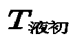 required by the heat exchange liquid may be as follows:

- is a constant specified for the power of the

heat exchange device 10, ΔT 2 is a constant,is the estimated initial temperature required for the heat exchange liquid stored in the
heat exchange pipe 202 when the temperature of the heat exchange requirement component is the upper limit of the normal working temperature when discharging ends,is the estimated heat exchange duration required for adjusting the temperature of the heat exchange liquid stored in the
heat exchange pipe 202 to the estimated initial temperature,is the upper limit of the normal working temperature of the heat exchange requirement component, is the upper limit of the normal working temperature of the heat exchange liquid in the
heat storage device 20 when discharging ends. - Then, the
second control component 203 calculates, based on the position information of the electric vehicle, estimated travel duration in which the movable charging vehicle travels to the electric vehicle, and calculates a time difference between a current moment and the required charging start moment. - If a sum of the estimated heat exchange duration and the estimated travel duration is not greater than the time difference, the
second control component 203 controls the movable charging vehicle to travel to a target heat exchange position, and sends a heat exchange connection request. The heat exchange connection request may be sent to a management platform, and the management platform may prompt a worker to perform a heat exchange connection. The worker may connect thethird connection port 2011 and thefourth connection port 2012 in theheat storage device 20 on the movable charging vehicle to thefirst connection port 1011 and thesecond connection port 1012 in theheat exchange device 10. - When it is detected that the connection statuses of the
first connection port 1011 and thesecond connection port 1012 are switched from disconnected to connected, thefirst control component 103 controls thepower pump 102 to be enabled to perform heat exchange. - After it is detected that the connection statuses of the
third connection port 2011 and thefourth connection port 2012 are both switched from disconnected to connected, when it is detected that the temperature of the heat exchange liquid stored in theheat exchange pipe 202 reaches the estimated initial temperature, the second control component sends the heat exchange stop request to thefirst control component 103, and sends the heat exchange disconnection request. The heat exchange connection request may also be sent to the management platform, and the management platform may prompt the worker to disconnect the heat exchange connection. The worker may disconnect thethird connection port 2011 and thefourth connection port 2012 in theheat storage device 20 on the movable charging vehicle from thefirst connection port 1011 and thesecond connection port 1012 in theheat exchange device 10. - When it is detected that the connection statuses of the
first connection port 1011 and thesecond connection port 1012 are switched from disconnected to connected, thefirst control component 103 controls thepower pump 102 to be enabled; and when receiving the heat exchange stop request, controls thepower pump 102 to be disabled. - When it is detected that the connection statuses of the third connection port (2011) and the
fourth connection port 2012 are both switched from connected to disconnected, thesecond control component 203 controls the movable charging vehicle to travel to the position corresponding to the position information of the electric vehicle. - If the sum of the estimated heat exchange duration and the estimated travel duration is greater than the time difference, the
second control component 203 sends an external liquid storage component connection request. A heat exchange management system herein may further include an externalliquid storage component 30, and the externalliquid storage component 30 stores heat exchange liquid of an appropriate temperature, for example, a heat exchange liquid of 30 degrees Celsius. As shown inFIG. 7 , a first port and a second port of the externalliquid storage component 30 are configured to connect respectively to thethird connection port 2011 and thefourth connection port 2012 that are in theheat storage device 20. In addition, to ensure that the external liquid storage component is connected to theheat storage device 20, the first port and the second port of theliquid storage component 30 may be the same as thefirst connection port 1011 and thesecond connection port 1012 in theheat exchange device 10. - The external liquid storage component connection request may also be sent to the management platform, and the management platform may prompt the worker to perform connection processing on the external liquid storage component. The worker may enable the first port and the second port of the external
liquid storage component 30 to connect respectively to thethird connection port 2011 and thefourth connection port 2012 that are in theheat storage device 20. Then, when it is detected that the connection statuses of thethird connection port 2011 and thefourth connection port 2012 are both switched from disconnected to connected, thesecond control component 203 controls the movable charging vehicle to travel to the position corresponding to the position information of the electric vehicle, and performs charging processing on the electric vehicle. - In addition, when the sum of the estimated heat exchange duration and the estimated travel duration is greater than the time difference, massof the heat exchange liquid in the external liquid storage component that needs to be carried may be calculated. An equation for calculating the mass
 of the heat exchange liquid in the external liquid storage component may be as follows:

- is the mass of the heat exchange liquid in the external liquid storage component that needs to be carried, and
 is a temperature of the heat exchange liquid stored in the external
liquid storage component 30, and the value is a constant. - Correspondingly, the external liquid storage component connection request may carry the mass of the heat exchange liquid in the external liquid storage component, and the worker may select an external liquid storage component that stores the massto connect to the

heat storage device 20. - In still another possible implementation, the heat exchange liquid in the
heat storage device 20 may be kept above the lower limit of the normal working temperature, for example, kept above 15 degrees Celsius. When the temperature of the heat exchange liquid is lower than the lower limit of the normal working temperature, heat exchange may be performed with theheat exchange device 10. In this way, it can be ensured that the heat exchange requirement component can be in the normal working temperature in cold weather, so as to provide a more efficient charging service. - In still another possible implementation, the
heat exchange device 10 may include a plurality of first connection components, and each connection component corresponds to one power pump. After one heat storage device is connected to a connection port of one first connection component, thefirst control component 103 may enable a corresponding power pump to perform a heat exchange task. In this way, oneheat exchange device 10 may perform heat exchange on a plurality of heat storage devices at the same time, thereby improving heat exchange efficiency. - An embodiment of this application further provides a heat management method. The heat management method may be applied to the heat management system in which the
heat exchange device 10 includes thetravel component 105 and theheat storage device 20 includes asecond control component 203. Refer toFIG. 8 . A procedure of the heat management method may include the following steps: - Step 801: The
second control component 203 sends a heat exchange request to afirst control component 103 when it is detected that a temperature of a heat exchange requirement component is not within a normal working temperature range. - The heat exchange request carries position information of the
heat storage device 20. - Step 802: The
first control component 103 controls thetravel component 105 to travel to a position corresponding to the position information. - Step 803: When it is detected that the
travel component 105 travels to the position corresponding to the position information, thefirst control component 103 sends a heat exchange connection request. - Step 804: When it is detected that connection statuses of a
first connection port 1011 and asecond connection port 1012 are switched from disconnected to connected, thefirst control component 103 controls apower pump 102 to be enabled. - Step 805: After it is detected that connection statuses of a
third connection port 2011 and afourth connection port 2012 are both switched from disconnected to connected, when it is detected that the temperature of the heat exchange requirement component is a target temperature, thesecond control component 203 sends a heat exchange stop request to thefirst control component 103. - Step 806: When receiving the heat exchange stop request, the
first control component 103 controls thepower pump 102 to be disabled. - It should be noted that, operations performed by the
first control component 103 and thesecond control component 203 in the foregoingstep 801 to step 805 are the same as operations performed by thefirst control component 103 and thesecond control component 203 when theheat exchange device 10 in the embodiment of the heat management system has the travel component. Details are not described herein again. - An embodiment of this application further provides still another heat management method. The heat management method may be applied to a heat management system in which the
heat storage device 20 includes thesecond control component 203, and theheat storage device 20 is deployed in a movable charging vehicle. Refer toFIG. 9A andFIG. 9B , a procedure of the heat management method may include the following steps: - Step 901: The
second control component 203 receives a charging request sent by an electric vehicle. - Step 902: The
second control component 203 obtains position information, required power, and required charging time that are of the electric vehicle and that are carried in the charging request, and calculates, based on the required power and the required charging time, an estimated temperature of a heat exchange requirement component after discharging ends. - Step 903: The
second control component 203 determines whether the estimated temperature of the heat exchange requirement component is higher than an upper limit of a normal working temperature. - Step 904: If determining that the estimated temperature of the heat exchange requirement component is not higher than the upper limit of the normal working temperature, the
second control component 203 controls the movable charging vehicle to travel to a position corresponding to the position information to perform charging processing. - Step 905: if determining that the estimated temperature of the heat exchange requirement component is higher than the upper limit of the normal working temperature, the
second control component 203 calculates, based on the required charging time and heat exchange power of theheat exchange device 10 in a case in which a temperature of the heat exchange requirement component is the upper limit of the normal working temperature when discharging ends, an estimated initial temperature required by heat exchange liquid stored in aheat exchange pipe 202 and estimated heat exchange duration required for adjusting a temperature of the heat exchange liquid stored in theheat exchange pipe 202 to the estimated initial temperature; calculates, based on the position information of the electric vehicle, estimated travel duration for the movable charging vehicle to travel to the electric vehicle; and calculates a time difference between a current moment and a required charging start moment. - Step 906: The
second control component 203 determines whether a sum of the estimated heat exchange duration and the estimated travel duration is greater than the time difference. - Step 907: If determining that the sum of the estimated heat exchange duration and the estimated travel duration is greater than the time difference, the
second control component 203 sends an external liquid storage component connection request, and when it is detected that connection statuses of athird connection port 2011 and afourth connection port 2012 are both switched from disconnected to connected, controls the movable charging vehicle to travel to the position corresponding to the position information to perform charging processing. - Step 908: If determining that the sum of the estimated heat exchange duration and the estimated travel duration is not greater than the time difference, the
second control component 203 controls the movable charging vehicle to travel to a target heat exchange position, and sends a heat exchange connection request. - Step 909: After it is detected that the connection statuses of the
third connection port 2011 and thefourth connection port 2012 are both switched from disconnected to connected, when it is detected that the temperature of the heat exchange liquid stored in theheat exchange pipe 202 reaches the estimated initial temperature, thesecond control component 203 sends a heat exchange stop request to thefirst control component 103, and sends a heat exchange disconnection request; and when it is detected that the connection statuses of thethird connection port 2011 and thefourth connection port 2012 are both switched from connected to disconnected, controls the movable charging vehicle to travel to a position corresponding to the position information to perform charging processing. - Step 910: When it is detected that connection statuses of a
first connection port 1011 and asecond connection port 1012 are switched from disconnected to connected, afirst control component 103 controls apower pump 102 to be enabled; and when receiving the heat exchange stop request, controls thepower pump 102 to be disabled. - It should be noted that, operations performed by the
first control component 103 and thesecond control component 203 in the foregoingstep 901 to step 910 are the same as operations performed by thefirst control component 103 and thesecond control component 203 when theheat storage device 20 in the embodiment of the heat management system is deployed on the movable charging vehicle. Details are not described herein again. -
FIG. 10 is a schematic diagram of a structure of a control component in a heat storage device according to an embodiment of this application. The control component in the heat storage device may be the second control component in the foregoing heat storage device. The control component in the heat storage device may vary greatly due to different configurations or performance, and may include one or more processors (central processing units, CPU) 1001 and one ormore memories 1002. Thememory 1002 stores at least one instruction, and the at least one instruction is loaded and executed by theprocessor 1001 to implement the control method for the heat storage device. -
FIG. 11 is a schematic diagram of a structure of a control component in a heat exchange device according to an embodiment of this application. The control component in the heat exchange device may be the first control component in the foregoing heat exchange device. The control component in the heat exchange device may vary greatly due to different configurations or performance, and may include one or more processors (central processing units, CPU) 1101 and one ormore memories 1102. Thememory 1102 stores at least one instruction, and the at least one instruction is loaded and executed by theprocessor 1101 to implement the control method for the heat exchange device. - The foregoing descriptions are merely example embodiments of this application, but are not intended to limit this application. Any modification, equivalent replacement, or improvement made without departing from the spirit and principle of this application should fall within the protection scope of this application.
Claims (23)
- A heat storage device, wherein the heat storage device comprises a second connection component (201) and a heat exchange pipe (202);the second connection component (201) comprises a third connection port (2011) and a fourth connection port (2012), and the third connection port (2011) and the fourth connection port (2012) are configured to connect respectively to a first connection port (1011) and a second connection port (1012) that are comprised in a first connection component (101) in a heat exchange device;two ports of the heat exchange pipe (202) are connected to the third connection port (2011) and the fourth connection port (2012) respectively, the second connection port (1012) is connected to a first port of a power pump (102) in the heat exchange device, the first connection port (1011) is connected to a first port of a liquid storage component (104) in the heat exchange device, and a second port of the liquid storage component (104) is connected to a second port of the power pump (102); andthe heat exchange pipe (202) is configured to store heat exchange liquid, and the heat exchange liquid stored in the heat exchange pipe (202) is used to perform heat exchange with a heat exchange requirement component.
- The heat storage device according to claim 1, wherein the heat storage device further comprises a second control component (203); and
the second control component (203) is configured to send a heat exchange request to a first control component (103) in the heat exchange device when it is detected that a temperature of the heat exchange requirement component is not within a normal working temperature range, wherein the heat exchange request carries position information of the heat storage device (20). - The heat storage device according to claim 2, wherein the second control component (203) is further configured to: after it is detected that connection statuses of the third connection port (2011) and the fourth connection port (2012) are both switched from disconnected to connected, and when it is detected that the temperature of the heat exchange requirement component is a first temperature, send a heat exchange stop request to the first control component (103).
- The heat storage device according to claim 1, wherein the heat storage device is deployed in a movable charging vehicle, the heat exchange requirement component belongs to the movable charging vehicle, and the heat storage device further comprises a second control component (203); and
the second control component (203) is configured to: receive a charging request sent by an electric vehicle; obtain position information and charging requirement information of the electric vehicle that are carried in the charging request, wherein the charging requirement information comprises at least one of required power and required charging time; calculate, based on the charging requirement information, an estimated temperature of the heat exchange requirement component after discharging ends; and if the estimated temperature of the heat exchange requirement component is not higher than an upper limit of a normal working temperature, control the movable charging vehicle to travel to a position corresponding to the position information to perform charging processing. - The heat storage device according to claim 4, wherein the charging request further carries a required charging start moment of the electric vehicle; and
the second control component (203) is further configured to: if the estimated temperature of the heat exchange requirement component is higher than the upper limit of the normal working temperature, calculate, based on the charging requirement information and heat exchange power of the heat exchange device in a case in which a temperature of the heat exchange requirement component is the upper limit of the normal working temperature when discharging ends, an estimated initial temperature required by the heat exchange liquid stored in the heat exchange pipe (202) and estimated heat exchange duration required for adjusting a temperature of the heat exchange liquid stored in the heat exchange pipe (202) to the estimated initial temperature; calculate, based on the position information of the electric vehicle, estimated travel duration for the movable charging vehicle to travel to the electric vehicle; calculate a time difference between a current moment and the required charging start moment; if a sum of the estimated heat exchange duration and the estimated travel duration is greater than the time difference, send an external liquid storage component connection request, wherein the external liquid storage component connection request is used to request to connect to an external liquid storage component (30), a first port and a second port of the external liquid storage component (30) are configured to connect to the third connection port (2011) and the fourth connection port (2012) respectively, and the external liquid storage component (30) is configured to store heat exchange liquid; and when it is detected that connection statuses of the third connection port (2011) and the fourth connection port (2012) are both switched from disconnected to connected, control the movable charging vehicle to travel to the position corresponding to the position information to perform charging processing. - The heat storage device according to claim 5, wherein the second control component (203) is further configured to: if the sum of the estimated heat exchange duration and the estimated travel duration is not greater than the time difference, control the movable charging vehicle to travel to a target heat exchange position, and send a heat exchange connection request; after it is detected that the connection statuses of the third connection port (2011) and the fourth connection port (2012) are both switched from disconnected to connected, when it is detected that the temperature of the heat exchange liquid stored in the heat exchange pipe (202) reaches the estimated initial temperature, send a heat exchange stop request to a first control component (103), and send a heat exchange disconnection request; and when it is detected that the connection statuses of the third connection port (2011) and the fourth connection port (2012) are both switched from connected to disconnected, control the movable charging vehicle to travel to the position corresponding to the position information to perform charging processing.
- The heat storage device according to claim 5 or 6, wherein the second connection component (201) further comprises a second connection detection circuit (2013), and the second connection detection circuit (2013) is configured to detect the connection statuses of the third connection port (2011) and the fourth connection port (2012), and send the connection statuses of the third connection port (2011) and the fourth connection port (2012) to the second control component (203).
- A heat exchange device, wherein the heat exchange device comprises a first connection component (101), a power pump (102), a first control component (103) and a liquid storage component (104);the first connection component (101) comprises a first connection port (1011) and a second connection port (1012), and the first connection port (1011) and the second connection port (1012) are configured to connect respectively to a third connection port (2011) and a fourth connection port (2012) that are comprised in a second connection component (201) in a heat storage device;the first connection port (1011) is connected to a first port of the liquid storage component (104), the first connection port (1012) is connected to a first port of the power pump (102), two ports of a heat exchange pipe (202) in the heat storage device are connected to the third connection port (2011) and the fourth connection port (2012) respectively, the liquid storage component (104) is configured to store heat storage liquid, the heat exchange pipe (202) is configured to store heat exchange liquid, and the heat exchange liquid stored in the heat exchange pipe (202) is used to perform heat exchange with a heat exchange requirement component; andthe first control component (103) is configured to control the power pump (102) to be enabled or disabled.
- The heat exchange device according to claim 8, wherein the heat exchange device (10) further comprises a travel component (105);the first connection component (101), the first control component (103), the liquid storage component (104), and the power pump (102) are disposed on the travel component (105); andthe first control component (103) is configured to: receive a heat exchange request sent by a second control component (203) in the heat storage device when it is detected that a temperature of the heat exchange requirement component is not within a normal working temperature range, and control the travel component (105) to travel to a position corresponding to position information of the heat storage device carried in the heat exchange request.
- The heat exchange device according to claim 9, wherein the first control component (103) is further configured to: send a heat exchange connection request when it is detected that the travel component (105) travels to the position corresponding to the position information, and when it is detected that connection statuses of the first connection port (1011) and the second connection port (1012) are switched from disconnected to connected, control the power pump (102) to be enabled; and
the first control component (103) is further configured to: when receiving a heat exchange stop request sent by the second control component (203), control the power pump (102) to be disabled. - The heat exchange device according to claim 10, wherein the first connection component (101) further comprises a first connection detection circuit (1013), wherein the first connection detection circuit (1013) is configured to: detect the connection statuses of the first connection port (1011) and the second connection port (1012); and send the connection statuses of the first connection port (1011) and the second connection port (1012) to the first control component (103).
- The heat exchange device according to claims 8 to 11, wherein the heat exchange device further comprises a temperature adjustment component (106); and
the temperature adjustment component (106) is configured to adjust a temperature of the heat exchange liquid in the liquid storage component (104) to a target temperature range. - The heat exchange device according to claim 12, wherein a first port and a second port of the temperature adjustment component (106) are connected to a third port of the liquid storage component (104) and a third port of the power pump (102) respectively; and
the first control component (103) is configured to: when it is detected that the temperature of the heat exchange liquid in the liquid storage component (104) is higher than an upper limit of the target temperature range, control the temperature adjustment component (106) to start a cooling mode, and control the power pump (102) to be enabled, so that the heat exchange liquid in the liquid storage component (104) circulates in the liquid storage component (104), the power pump (102), and the temperature adjustment component (106); and when it is detected that the temperature of the heat exchange liquid in the liquid storage component (104) is within the target temperature range, control the temperature adjustment component (106) and the power pump (102) to be disabled. - The heat exchange device according to claim 13, wherein the first control component (103) is further configured to: when it is detected that the temperature of the heat exchange liquid in the liquid storage component (104) is lower than a lower limit of the target temperature range, control the temperature adjustment component (106) to start a heating mode, and control the power pump (102) to be enabled, so that the heat exchange liquid in the liquid storage component (104) circulates in the liquid storage component (104), the power pump (102), and the temperature adjustment component (106); and when it is detected that the temperature of the heat exchange liquid in the liquid storage component (104) is within the target temperature range, control the temperature adjustment component (106) and the power pump (102) to be disabled.
- A control method for a heat storage device, wherein the control method is applied to the heat storage device according to claim 1, the heat storage device further comprises a second control component (203), and the control method comprises:receiving, by the second control component (203), a charging request sent by an electric vehicle, wherein the charging request carries position information and charging requirement information of the electric vehicle, and the charging requirement information comprises at least one of required power and required charging time; andcalculating, by the second control component (203) based on the charging requirement information, an estimated temperature of the heat exchange requirement component after discharging ends, and if the estimated temperature of the heat exchange requirement component is not higher than an upper limit of a normal working temperature, controlling a movable charging vehicle to travel to a position corresponding to the position information to perform charging processing.
- The control method according to claim 15, wherein the charging request further carries a required charging start moment of the electric vehicle, and the control method further comprises:if the estimated temperature of the heat exchange requirement component is higher than the upper limit of the normal working temperature, calculating, by the second control component (203) based on the charging requirement information and heat exchange power of the heat exchange device in a case in which the temperature of the heat exchange requirement component is the upper limit of the normal working temperature when discharging ends, an estimated initial temperature required for heat exchange liquid stored in the heat exchange pipe (202) and estimated heat exchange duration required for adjusting a temperature of the heat exchange liquid stored in the heat exchange pipe (202) to the estimated initial temperature;calculating, by the second control component (203) based on the position information of the electric vehicle, estimated travel duration in which the movable charging vehicle travels to the electric vehicle, and calculating a time difference between a current moment and the required charging start moment; andif a sum of the estimated heat exchange duration and the estimated travel duration is greater than the time difference, sending, by the second control component (203), an external liquid storage component connection request, and when it is detected that connection statuses of the third connection port (2011) and the fourth connection port (2012) are both switched from disconnected to connected, controlling the movable charging vehicle to travel to the position corresponding to the position information to perform charging processing.
- The control method according to claim 15 or 16, wherein the control method further comprises:if the sum of the estimated heat exchange duration and the estimated travel duration is not greater than the time difference, controlling, by the second control component (203), the movable charging vehicle to travel to a target heat exchange position, and sending a heat exchange connection request;after it is detected that the connection statuses of the third connection port (2011) and the fourth connection port (2012) are both switched from disconnected to connected, when it is detected that the temperature of the heat exchange liquid stored in the heat exchange pipe (202) reaches the estimated initial temperature, sending, by the second control component (203), a heat exchange stop request to a first control component (103) in a heat exchange device, and sending a heat exchange disconnection request; andwhen it is detected that the connection statuses of the third connection port (2011) and the fourth connection port (2012) are both switched from connected to disconnected, controlling, by the second control component (203), the movable charging vehicle to travel to the position corresponding to the position information to perform charging processing.
- A control method for a heat exchange system, wherein the control method is applied to the heat exchange device according to claim 8, the heat exchange device further comprises a travel component (105), and the control method comprises:receiving, by a first control component (103), a heat exchange request sent by a heat storage device, wherein the heat exchange request carries position information of the heat storage device;controlling, by the first control component (103), the travel component (105) to travel to a position corresponding to the position information;sending, by the first control component (103), a heat exchange connection request when it is detected that the travel component (105) travels to the position corresponding to the position information, and when it is detected that connection statuses of a first connection port (1011) and a second connection port (1012) are switched from disconnected to connected, controlling the power pump (102) to be enabled; andwhen receiving a heat exchange stop request sent by a second control component (203), controlling, by the first control component (103), the power pump (102) to be disabled.
- The control method according to claim 18, wherein the control method further comprises:when it is detected that a temperature of heat exchange liquid in the liquid storage component (104) is higher than an upper limit of a target temperature range, controlling, by the first control component (103), the temperature adjustment component (106) to start a cooling mode, and controlling the power pump (102) to be enabled, so that the heat exchange liquid in the liquid storage component (104) circulates in the liquid storage component (104), the power pump (102), and the temperature adjustment component (106); andwhen it is detected that the temperature of the heat exchange liquid in the liquid storage component (104) is within the target temperature range, controlling, by the first control component (103), the temperature adjustment component (106) and the power pump (102) to be disabled.
- The control method according to claim 19, wherein the control method further comprises:when it is detected that the temperature of the heat exchange liquid in the liquid storage component (104) is lower than a lower limit of the target temperature range, controlling, by the first control component (103), the temperature adjustment component (106) to start a heating mode, and controlling the power pump (102) to be enabled, so that the heat exchange liquid in the liquid storage component (104) circulates in the liquid storage component (104), the power pump (102), and the temperature adjustment component (106); andwhen it is detected that the temperature of the heat exchange liquid in the liquid storage component (104) is within the target temperature range, controlling, by the first control component (103), the temperature adjustment component (106) and the power pump (102) to be disabled.
- A heat management system, wherein the heat management system comprises the heat storage device according to claims 1 to 7 and the heat exchange device according to claims 8 to 11.
- A control component in a heat storage device, wherein the control component comprises a processor and a memory, the memory stores at least one instruction, and the instruction is loaded and executed by the processor to implement an operation performed by the control method according to any one of claims 15 to 17.
- A control component in a heat exchange device, wherein the control component comprises a processor and a memory, the memory stores at least one instruction, and the instruction is loaded and executed by the processor to implement an operation performed by the control method according to any one of claims 18 to 20.
Applications Claiming Priority (1)
| Application Number | Priority Date | Filing Date | Title |
|---|---|---|---|
| PCT/CN2020/110106 WO2022036608A1 (en) | 2020-08-19 | 2020-08-19 | Heat storage apparatus, heat exchange apparatus, control method, control component and thermal management system |
Publications (2)
| Publication Number | Publication Date |
|---|---|
| EP4187187A1 true EP4187187A1 (en) | 2023-05-31 |
| EP4187187A4 EP4187187A4 (en) | 2023-11-22 |
Family
ID=75609435
Family Applications (1)
| Application Number | Title | Priority Date | Filing Date |
|---|---|---|---|
| EP20949819.5A Pending EP4187187A4 (en) | 2020-08-19 | 2020-08-19 | HEAT STORAGE APPARATUS, HEAT EXCHANGE APPARATUS, CONTROL METHOD, CONTROL ELEMENT AND THERMAL MANAGEMENT SYSTEM |
Country Status (3)
| Country | Link |
|---|---|
| EP (1) | EP4187187A4 (en) |
| CN (1) | CN112740461B (en) |
| WO (1) | WO2022036608A1 (en) |
Families Citing this family (3)
| Publication number | Priority date | Publication date | Assignee | Title |
|---|---|---|---|---|
| CN113258639A (en) * | 2021-05-17 | 2021-08-13 | 爱驰汽车有限公司 | Mobile charging robot |
| CN113942407B (en) * | 2021-11-29 | 2024-01-23 | 宁波三星智能电气有限公司 | Charging device and control method |
| CN114664165B (en) * | 2022-03-25 | 2023-07-28 | 北京智扬北方国际教育科技有限公司 | New energy automobile thermal management display system |
Family Cites Families (13)
| Publication number | Priority date | Publication date | Assignee | Title |
|---|---|---|---|---|
| JP2518756B2 (en) * | 1991-11-02 | 1996-07-31 | 東北電力株式会社 | Storage battery heating and rapid heating system for electric vehicles |
| CN201191052Y (en) * | 2008-03-19 | 2009-02-04 | 杭州瑞丰电子控制技术有限公司 | Thermal storage unit equipment |
| DE102009024497A1 (en) * | 2009-06-08 | 2010-12-09 | Triesch, Frank, Dr. Ing. | Cogeneration |
| US9786961B2 (en) * | 2011-07-25 | 2017-10-10 | Lightening Energy | Rapid charging electric vehicle and method and apparatus for rapid charging |
| US10340709B2 (en) * | 2011-07-29 | 2019-07-02 | Lightening Energy | Electric battery rapid recharging system including a mobile charging station having a coolant supply line and an electrical supply line |
| EP3103158B1 (en) * | 2014-02-03 | 2020-05-13 | Phinergy Ltd. | Thermal battery for heating vehicles |
| CN104577254B (en) * | 2014-12-23 | 2016-10-05 | 吉林大学 | A kind of Thermal Management System for EV Battery Packs and method of work thereof |
| CN107128153B (en) * | 2017-05-16 | 2019-06-04 | 上海理工大学 | Thermal energy storage heating system with waste heat recovery for electric vehicles |
| CN108448198B (en) * | 2018-01-19 | 2020-05-05 | 浙江南都电源动力股份有限公司 | Split type battery thermal management system, method of using the same, and rapid charging system |
| CN109017407A (en) * | 2018-08-16 | 2018-12-18 | 北京新能源汽车股份有限公司 | Battery heat exchange control device, charging pile and battery heat exchange system |
| KR102540934B1 (en) * | 2018-11-29 | 2023-06-08 | 현대자동차주식회사 | Battery charging system for an electric vehicle and method for charging an electric vehicle |
| CN210000201U (en) * | 2019-02-28 | 2020-01-31 | 冀中能源井陉矿业集团有限公司 | Mobile energy storage vehicle |
| CN109974064A (en) * | 2019-04-16 | 2019-07-05 | 南京金合能源材料有限公司 | Mobile phase-change heat accumulation system based on the heating of charging pile electricity |
-
2020
- 2020-08-19 EP EP20949819.5A patent/EP4187187A4/en active Pending
- 2020-08-19 WO PCT/CN2020/110106 patent/WO2022036608A1/en not_active Ceased
- 2020-08-19 CN CN202080005141.6A patent/CN112740461B/en active Active
Also Published As
| Publication number | Publication date |
|---|---|
| CN112740461A (en) | 2021-04-30 |
| WO2022036608A1 (en) | 2022-02-24 |
| CN112740461B (en) | 2022-05-06 |
| EP4187187A4 (en) | 2023-11-22 |
Similar Documents
| Publication | Publication Date | Title |
|---|---|---|
| US12322775B2 (en) | Traction battery thermal management | |
| EP3549813B1 (en) | Vehicle and method of charging a vehicle | |
| JP6687895B2 (en) | Vehicle fuel cell warm-up device | |
| US12441202B2 (en) | Battery charging and swap station, thermal management system and control method therefor, control device, and medium | |
| US11605849B2 (en) | Thermal management system for high power electrical equipment | |
| CN109585973B (en) | Power battery thermal management method and system | |
| EP4696546A1 (en) | Liquid cooling device and charging pile | |
| CN112740461B (en) | Thermal storage device, heat exchange device, control method, control component, and thermal management system | |
| JP7574883B2 (en) | Vehicle and method for charging the vehicle | |
| CN114312484B (en) | Thermal management device, thermal management system and new energy automobile | |
| CN116198285B (en) | Thermal management system, thermal management method, electronic device and vehicle | |
| CN114312471A (en) | Thermal management method and system for power battery of extended-range vehicle and storage medium | |
| JP2021175255A (en) | vehicle | |
| US20240066954A1 (en) | Heating control method for vehicle | |
| US20210265853A1 (en) | Method for controlling the charging process of an electrical energy storage device, and charging device, as well as system consisting of electrified vehicle and charging device | |
| CN114590239B (en) | Hybrid vehicle thermal management system control method, device and storage medium | |
| KR20160081090A (en) | Apparatus and method for controlling temperature of battery pack in eco-friendley vehicles | |
| KR20250106042A (en) | Apparatus for controlling vehicle and method thereof | |
| CN116834510A (en) | Vehicle heat exchange system, control method, device and storage medium | |
| CN117584814A (en) | Power battery heating method, whole vehicle controller, equipment, medium and automobile | |
| US20250196718A1 (en) | Temperature control system | |
| US20240380017A1 (en) | Stand-alone thermal management system for a battery system of a machine | |
| CN115320416B (en) | Power system and vehicle | |
| CN119674323A (en) | A battery pack heat dissipation method based on phase change material and heat dissipation pipe | |
| WO2024090342A1 (en) | Cooling system |
Legal Events
| Date | Code | Title | Description |
|---|---|---|---|
| STAA | Information on the status of an ep patent application or granted ep patent |
Free format text: STATUS: THE INTERNATIONAL PUBLICATION HAS BEEN MADE |
|
| PUAI | Public reference made under article 153(3) epc to a published international application that has entered the european phase |
Free format text: ORIGINAL CODE: 0009012 |
|
| STAA | Information on the status of an ep patent application or granted ep patent |
Free format text: STATUS: REQUEST FOR EXAMINATION WAS MADE |
|
| 17P | Request for examination filed |
Effective date: 20230221 |
|
| AK | Designated contracting states |
Kind code of ref document: A1 Designated state(s): AL AT BE BG CH CY CZ DE DK EE ES FI FR GB GR HR HU IE IS IT LI LT LU LV MC MK MT NL NO PL PT RO RS SE SI SK SM TR |
|
| A4 | Supplementary search report drawn up and despatched |
Effective date: 20231023 |
|
| DAV | Request for validation of the european patent (deleted) | ||
| DAX | Request for extension of the european patent (deleted) | ||
| RIC1 | Information provided on ipc code assigned before grant |
Ipc: F28D 21/00 20060101ALI20231017BHEP Ipc: F28D 20/00 20060101ALI20231017BHEP Ipc: B60L 58/26 20190101ALI20231017BHEP Ipc: B60L 53/60 20190101ALI20231017BHEP Ipc: F28D 20/02 20060101AFI20231017BHEP |
|
| RAP1 | Party data changed (applicant data changed or rights of an application transferred) |
Owner name: SHENZHEN YINWANG INTELLIGENTTECHNOLOGIES CO., LTD. |