EP4187120A1 - Disk brake device - Google Patents
Disk brake device Download PDFInfo
- Publication number
- EP4187120A1 EP4187120A1 EP21845198.7A EP21845198A EP4187120A1 EP 4187120 A1 EP4187120 A1 EP 4187120A1 EP 21845198 A EP21845198 A EP 21845198A EP 4187120 A1 EP4187120 A1 EP 4187120A1
- Authority
- EP
- European Patent Office
- Prior art keywords
- main body
- cap
- piston
- brake device
- rotation direction
- Prior art date
- Legal status (The legal status is an assumption and is not a legal conclusion. Google has not performed a legal analysis and makes no representation as to the accuracy of the status listed.)
- Pending
Links
- 230000001105 regulatory effect Effects 0.000 claims description 90
- 230000007246 mechanism Effects 0.000 claims description 44
- 238000006243 chemical reaction Methods 0.000 claims description 23
- 230000005540 biological transmission Effects 0.000 claims description 20
- 229910052751 metal Inorganic materials 0.000 claims description 15
- 239000002184 metal Substances 0.000 claims description 15
- 239000003921 oil Substances 0.000 description 41
- 238000005192 partition Methods 0.000 description 28
- 230000002093 peripheral effect Effects 0.000 description 27
- 230000004308 accommodation Effects 0.000 description 19
- 230000008878 coupling Effects 0.000 description 18
- 238000010168 coupling process Methods 0.000 description 18
- 238000005859 coupling reaction Methods 0.000 description 18
- 238000003825 pressing Methods 0.000 description 16
- 230000009467 reduction Effects 0.000 description 11
- 230000004048 modification Effects 0.000 description 10
- 238000012986 modification Methods 0.000 description 10
- 229920003002 synthetic resin Polymers 0.000 description 9
- 239000000057 synthetic resin Substances 0.000 description 9
- 238000006073 displacement reaction Methods 0.000 description 7
- 230000000694 effects Effects 0.000 description 7
- XEEYBQQBJWHFJM-UHFFFAOYSA-N Iron Chemical compound [Fe] XEEYBQQBJWHFJM-UHFFFAOYSA-N 0.000 description 6
- 229910045601 alloy Inorganic materials 0.000 description 5
- 239000000956 alloy Substances 0.000 description 5
- 239000000428 dust Substances 0.000 description 4
- 229910000975 Carbon steel Inorganic materials 0.000 description 3
- 239000010962 carbon steel Substances 0.000 description 3
- 239000003638 chemical reducing agent Substances 0.000 description 3
- 239000010720 hydraulic oil Substances 0.000 description 3
- 229910052742 iron Inorganic materials 0.000 description 3
- 230000007257 malfunction Effects 0.000 description 3
- 238000000465 moulding Methods 0.000 description 3
- 239000010935 stainless steel Substances 0.000 description 3
- 229910001220 stainless steel Inorganic materials 0.000 description 3
- 239000000725 suspension Substances 0.000 description 3
- RTAQQCXQSZGOHL-UHFFFAOYSA-N Titanium Chemical compound [Ti] RTAQQCXQSZGOHL-UHFFFAOYSA-N 0.000 description 2
- 229910052782 aluminium Inorganic materials 0.000 description 2
- XAGFODPZIPBFFR-UHFFFAOYSA-N aluminium Chemical compound [Al] XAGFODPZIPBFFR-UHFFFAOYSA-N 0.000 description 2
- 230000006866 deterioration Effects 0.000 description 2
- 238000010586 diagram Methods 0.000 description 2
- 239000010936 titanium Substances 0.000 description 2
- 229910052719 titanium Inorganic materials 0.000 description 2
- 229910000838 Al alloy Inorganic materials 0.000 description 1
- 229910001018 Cast iron Inorganic materials 0.000 description 1
- 239000013013 elastic material Substances 0.000 description 1
- 239000012530 fluid Substances 0.000 description 1
- 239000002783 friction material Substances 0.000 description 1
- 230000017525 heat dissipation Effects 0.000 description 1
- 229910001234 light alloy Inorganic materials 0.000 description 1
- 238000004519 manufacturing process Methods 0.000 description 1
- 238000000034 method Methods 0.000 description 1
- 230000000149 penetrating effect Effects 0.000 description 1
- 230000008569 process Effects 0.000 description 1
- 238000007788 roughening Methods 0.000 description 1
- 102200082907 rs33918131 Human genes 0.000 description 1
- 102200082816 rs34868397 Human genes 0.000 description 1
- 238000004904 shortening Methods 0.000 description 1
- 230000003746 surface roughness Effects 0.000 description 1
Images










Classifications
-
- B—PERFORMING OPERATIONS; TRANSPORTING
- B60—VEHICLES IN GENERAL
- B60T—VEHICLE BRAKE CONTROL SYSTEMS OR PARTS THEREOF; BRAKE CONTROL SYSTEMS OR PARTS THEREOF, IN GENERAL; ARRANGEMENT OF BRAKING ELEMENTS ON VEHICLES IN GENERAL; PORTABLE DEVICES FOR PREVENTING UNWANTED MOVEMENT OF VEHICLES; VEHICLE MODIFICATIONS TO FACILITATE COOLING OF BRAKES
- B60T13/00—Transmitting braking action from initiating means to ultimate brake actuator with power assistance or drive; Brake systems incorporating such transmitting means, e.g. air-pressure brake systems
- B60T13/10—Transmitting braking action from initiating means to ultimate brake actuator with power assistance or drive; Brake systems incorporating such transmitting means, e.g. air-pressure brake systems with fluid assistance, drive, or release
- B60T13/58—Combined or convertible systems
- B60T13/588—Combined or convertible systems both fluid and mechanical assistance or drive
-
- B—PERFORMING OPERATIONS; TRANSPORTING
- B60—VEHICLES IN GENERAL
- B60T—VEHICLE BRAKE CONTROL SYSTEMS OR PARTS THEREOF; BRAKE CONTROL SYSTEMS OR PARTS THEREOF, IN GENERAL; ARRANGEMENT OF BRAKING ELEMENTS ON VEHICLES IN GENERAL; PORTABLE DEVICES FOR PREVENTING UNWANTED MOVEMENT OF VEHICLES; VEHICLE MODIFICATIONS TO FACILITATE COOLING OF BRAKES
- B60T1/00—Arrangements of braking elements, i.e. of those parts where braking effect occurs specially for vehicles
- B60T1/02—Arrangements of braking elements, i.e. of those parts where braking effect occurs specially for vehicles acting by retarding wheels
- B60T1/06—Arrangements of braking elements, i.e. of those parts where braking effect occurs specially for vehicles acting by retarding wheels acting otherwise than on tread, e.g. employing rim, drum, disc, or transmission or on double wheels
- B60T1/065—Arrangements of braking elements, i.e. of those parts where braking effect occurs specially for vehicles acting by retarding wheels acting otherwise than on tread, e.g. employing rim, drum, disc, or transmission or on double wheels employing disc
-
- B—PERFORMING OPERATIONS; TRANSPORTING
- B60—VEHICLES IN GENERAL
- B60T—VEHICLE BRAKE CONTROL SYSTEMS OR PARTS THEREOF; BRAKE CONTROL SYSTEMS OR PARTS THEREOF, IN GENERAL; ARRANGEMENT OF BRAKING ELEMENTS ON VEHICLES IN GENERAL; PORTABLE DEVICES FOR PREVENTING UNWANTED MOVEMENT OF VEHICLES; VEHICLE MODIFICATIONS TO FACILITATE COOLING OF BRAKES
- B60T13/00—Transmitting braking action from initiating means to ultimate brake actuator with power assistance or drive; Brake systems incorporating such transmitting means, e.g. air-pressure brake systems
- B60T13/74—Transmitting braking action from initiating means to ultimate brake actuator with power assistance or drive; Brake systems incorporating such transmitting means, e.g. air-pressure brake systems with electrical assistance or drive
- B60T13/741—Transmitting braking action from initiating means to ultimate brake actuator with power assistance or drive; Brake systems incorporating such transmitting means, e.g. air-pressure brake systems with electrical assistance or drive acting on an ultimate actuator
-
- B—PERFORMING OPERATIONS; TRANSPORTING
- B60—VEHICLES IN GENERAL
- B60T—VEHICLE BRAKE CONTROL SYSTEMS OR PARTS THEREOF; BRAKE CONTROL SYSTEMS OR PARTS THEREOF, IN GENERAL; ARRANGEMENT OF BRAKING ELEMENTS ON VEHICLES IN GENERAL; PORTABLE DEVICES FOR PREVENTING UNWANTED MOVEMENT OF VEHICLES; VEHICLE MODIFICATIONS TO FACILITATE COOLING OF BRAKES
- B60T13/00—Transmitting braking action from initiating means to ultimate brake actuator with power assistance or drive; Brake systems incorporating such transmitting means, e.g. air-pressure brake systems
- B60T13/74—Transmitting braking action from initiating means to ultimate brake actuator with power assistance or drive; Brake systems incorporating such transmitting means, e.g. air-pressure brake systems with electrical assistance or drive
- B60T13/746—Transmitting braking action from initiating means to ultimate brake actuator with power assistance or drive; Brake systems incorporating such transmitting means, e.g. air-pressure brake systems with electrical assistance or drive and mechanical transmission of the braking action
-
- F—MECHANICAL ENGINEERING; LIGHTING; HEATING; WEAPONS; BLASTING
- F16—ENGINEERING ELEMENTS AND UNITS; GENERAL MEASURES FOR PRODUCING AND MAINTAINING EFFECTIVE FUNCTIONING OF MACHINES OR INSTALLATIONS; THERMAL INSULATION IN GENERAL
- F16D—COUPLINGS FOR TRANSMITTING ROTATION; CLUTCHES; BRAKES
- F16D55/00—Brakes with substantially-radial braking surfaces pressed together in axial direction, e.g. disc brakes
- F16D55/02—Brakes with substantially-radial braking surfaces pressed together in axial direction, e.g. disc brakes with axially-movable discs or pads pressed against axially-located rotating members
- F16D55/22—Brakes with substantially-radial braking surfaces pressed together in axial direction, e.g. disc brakes with axially-movable discs or pads pressed against axially-located rotating members by clamping an axially-located rotating disc between movable braking members, e.g. movable brake discs or brake pads
- F16D55/224—Brakes with substantially-radial braking surfaces pressed together in axial direction, e.g. disc brakes with axially-movable discs or pads pressed against axially-located rotating members by clamping an axially-located rotating disc between movable braking members, e.g. movable brake discs or brake pads with a common actuating member for the braking members
- F16D55/225—Brakes with substantially-radial braking surfaces pressed together in axial direction, e.g. disc brakes with axially-movable discs or pads pressed against axially-located rotating members by clamping an axially-located rotating disc between movable braking members, e.g. movable brake discs or brake pads with a common actuating member for the braking members the braking members being brake pads
- F16D55/226—Brakes with substantially-radial braking surfaces pressed together in axial direction, e.g. disc brakes with axially-movable discs or pads pressed against axially-located rotating members by clamping an axially-located rotating disc between movable braking members, e.g. movable brake discs or brake pads with a common actuating member for the braking members the braking members being brake pads in which the common actuating member is moved axially, e.g. floating caliper disc brakes
-
- F—MECHANICAL ENGINEERING; LIGHTING; HEATING; WEAPONS; BLASTING
- F16—ENGINEERING ELEMENTS AND UNITS; GENERAL MEASURES FOR PRODUCING AND MAINTAINING EFFECTIVE FUNCTIONING OF MACHINES OR INSTALLATIONS; THERMAL INSULATION IN GENERAL
- F16D—COUPLINGS FOR TRANSMITTING ROTATION; CLUTCHES; BRAKES
- F16D55/00—Brakes with substantially-radial braking surfaces pressed together in axial direction, e.g. disc brakes
- F16D55/02—Brakes with substantially-radial braking surfaces pressed together in axial direction, e.g. disc brakes with axially-movable discs or pads pressed against axially-located rotating members
- F16D55/22—Brakes with substantially-radial braking surfaces pressed together in axial direction, e.g. disc brakes with axially-movable discs or pads pressed against axially-located rotating members by clamping an axially-located rotating disc between movable braking members, e.g. movable brake discs or brake pads
- F16D55/228—Brakes with substantially-radial braking surfaces pressed together in axial direction, e.g. disc brakes with axially-movable discs or pads pressed against axially-located rotating members by clamping an axially-located rotating disc between movable braking members, e.g. movable brake discs or brake pads with a separate actuating member for each side
-
- F—MECHANICAL ENGINEERING; LIGHTING; HEATING; WEAPONS; BLASTING
- F16—ENGINEERING ELEMENTS AND UNITS; GENERAL MEASURES FOR PRODUCING AND MAINTAINING EFFECTIVE FUNCTIONING OF MACHINES OR INSTALLATIONS; THERMAL INSULATION IN GENERAL
- F16D—COUPLINGS FOR TRANSMITTING ROTATION; CLUTCHES; BRAKES
- F16D65/00—Parts or details
- F16D65/14—Actuating mechanisms for brakes; Means for initiating operation at a predetermined position
- F16D65/16—Actuating mechanisms for brakes; Means for initiating operation at a predetermined position arranged in or on the brake
- F16D65/18—Actuating mechanisms for brakes; Means for initiating operation at a predetermined position arranged in or on the brake adapted for drawing members together, e.g. for disc brakes
-
- F—MECHANICAL ENGINEERING; LIGHTING; HEATING; WEAPONS; BLASTING
- F16—ENGINEERING ELEMENTS AND UNITS; GENERAL MEASURES FOR PRODUCING AND MAINTAINING EFFECTIVE FUNCTIONING OF MACHINES OR INSTALLATIONS; THERMAL INSULATION IN GENERAL
- F16D—COUPLINGS FOR TRANSMITTING ROTATION; CLUTCHES; BRAKES
- F16D65/00—Parts or details
- F16D65/14—Actuating mechanisms for brakes; Means for initiating operation at a predetermined position
- F16D65/16—Actuating mechanisms for brakes; Means for initiating operation at a predetermined position arranged in or on the brake
- F16D65/18—Actuating mechanisms for brakes; Means for initiating operation at a predetermined position arranged in or on the brake adapted for drawing members together, e.g. for disc brakes
- F16D65/183—Actuating mechanisms for brakes; Means for initiating operation at a predetermined position arranged in or on the brake adapted for drawing members together, e.g. for disc brakes with force-transmitting members arranged side by side acting on a spot type force-applying member
-
- F—MECHANICAL ENGINEERING; LIGHTING; HEATING; WEAPONS; BLASTING
- F16—ENGINEERING ELEMENTS AND UNITS; GENERAL MEASURES FOR PRODUCING AND MAINTAINING EFFECTIVE FUNCTIONING OF MACHINES OR INSTALLATIONS; THERMAL INSULATION IN GENERAL
- F16D—COUPLINGS FOR TRANSMITTING ROTATION; CLUTCHES; BRAKES
- F16D65/00—Parts or details
- F16D65/78—Features relating to cooling
- F16D2065/785—Heat insulation or reflection
-
- F—MECHANICAL ENGINEERING; LIGHTING; HEATING; WEAPONS; BLASTING
- F16—ENGINEERING ELEMENTS AND UNITS; GENERAL MEASURES FOR PRODUCING AND MAINTAINING EFFECTIVE FUNCTIONING OF MACHINES OR INSTALLATIONS; THERMAL INSULATION IN GENERAL
- F16D—COUPLINGS FOR TRANSMITTING ROTATION; CLUTCHES; BRAKES
- F16D2121/00—Type of actuator operation force
- F16D2121/02—Fluid pressure
- F16D2121/04—Fluid pressure acting on a piston-type actuator, e.g. for liquid pressure
-
- F—MECHANICAL ENGINEERING; LIGHTING; HEATING; WEAPONS; BLASTING
- F16—ENGINEERING ELEMENTS AND UNITS; GENERAL MEASURES FOR PRODUCING AND MAINTAINING EFFECTIVE FUNCTIONING OF MACHINES OR INSTALLATIONS; THERMAL INSULATION IN GENERAL
- F16D—COUPLINGS FOR TRANSMITTING ROTATION; CLUTCHES; BRAKES
- F16D2121/00—Type of actuator operation force
- F16D2121/18—Electric or magnetic
- F16D2121/24—Electric or magnetic using motors
-
- F—MECHANICAL ENGINEERING; LIGHTING; HEATING; WEAPONS; BLASTING
- F16—ENGINEERING ELEMENTS AND UNITS; GENERAL MEASURES FOR PRODUCING AND MAINTAINING EFFECTIVE FUNCTIONING OF MACHINES OR INSTALLATIONS; THERMAL INSULATION IN GENERAL
- F16D—COUPLINGS FOR TRANSMITTING ROTATION; CLUTCHES; BRAKES
- F16D2123/00—Multiple operation forces
-
- F—MECHANICAL ENGINEERING; LIGHTING; HEATING; WEAPONS; BLASTING
- F16—ENGINEERING ELEMENTS AND UNITS; GENERAL MEASURES FOR PRODUCING AND MAINTAINING EFFECTIVE FUNCTIONING OF MACHINES OR INSTALLATIONS; THERMAL INSULATION IN GENERAL
- F16D—COUPLINGS FOR TRANSMITTING ROTATION; CLUTCHES; BRAKES
- F16D2125/00—Components of actuators
- F16D2125/02—Fluid-pressure mechanisms
- F16D2125/06—Pistons
-
- F—MECHANICAL ENGINEERING; LIGHTING; HEATING; WEAPONS; BLASTING
- F16—ENGINEERING ELEMENTS AND UNITS; GENERAL MEASURES FOR PRODUCING AND MAINTAINING EFFECTIVE FUNCTIONING OF MACHINES OR INSTALLATIONS; THERMAL INSULATION IN GENERAL
- F16D—COUPLINGS FOR TRANSMITTING ROTATION; CLUTCHES; BRAKES
- F16D2125/00—Components of actuators
- F16D2125/18—Mechanical mechanisms
- F16D2125/20—Mechanical mechanisms converting rotation to linear movement or vice versa
- F16D2125/34—Mechanical mechanisms converting rotation to linear movement or vice versa acting in the direction of the axis of rotation
- F16D2125/40—Screw-and-nut
Definitions
- the present invention relates to a disc brake device.
- a disc brake device Since a disc brake device is excellent in heat dissipation and can finely adjust a braking force during traveling, the number of cases in which the disc brake device is adopted not only for front wheels of an automobile but also for rear wheels of the automobile is increased.
- the disc brake device can be roughly divided into a hydraulic disc brake device that uses hydraulic oil to obtain a braking force and an electric disc brake device that uses an actuator that can be electrically driven to obtain a braking force.
- an electric parking brake type structure in which a braking force of a service brake is generated by feeding brake oil (fluid) into a cylinder, and a braking force of a parking brake is generated using an electric actuator such as a rotary-to-linear motion conversion mechanism.
- the brake oil is accommodated in the cylinder, and thus, a pad heats up when pressed against a rotating rotor, heat is transferred to the brake oil via a piston, and the temperature of the brake oil is likely to rise.
- the temperature of the brake oil rises, deterioration of the brake oil is caused, which causes a vapor lock phenomenon.
- the piston may be used as a divided structure as disclosed in JP2015-25550A .
- the piston may include a piston main body that is fitted to the cylinder and receives a hydraulic pressure, and a piston cap that presses the pad. According to this configuration, the amount of heat transferred to the brake oil can be reduced as compared with a case where the piston has an integral structure. Therefore, it is possible to prevent an increase in temperature of the brake oil.
- a rotary-to-linear motion conversion mechanism including a spindle as a rotary member and a nut as a linear motion member
- a slip may occur between the piston cap and the piston main body on which a torque is applied from a nut, and the piston main body may idle together with the nut. Therefore, it is difficult to stably obtain the braking force of the parking brake.
- the spindle when the spindle is driven to rotate in a reverse rotation direction to release the braking force of the parking brake, the nut is moved (fully released) to a limit position on a side opposite to a rotor, so that the nut and the spindle are brought into a locked state (that is, the nut cannot be further moved in an axial direction along with rotation of the spindle, and the nut is brought into a state of being forcibly rotated together with the spindle).
- an electric motor as a drive source may reach a stall torque (maximum current).
- the present invention has been made to solve the above problems, and an object thereof is to provide an electric parking brake type disc brake device that can stably obtain a braking force of a parking brake while having a structure capable of preventing a temperature rise of brake oil, and can solve a problem caused when a linear motion member is fully released to a side opposite to a rotor.
- a disc brake device includes a pad, a caliper, a piston, and a rotary-to-linear motion conversion mechanism.
- the caliper includes a cylinder having an opening on a pad side.
- the piston is fitted to the cylinder and configured to press the pad toward a rotor.
- the rotary-to-linear motion conversion mechanism is configured to convert a rotary motion of a drive source into a linear motion to push the piston toward the rotor.
- the disc brake device is configured to generate a braking force of a service brake by feeding brake oil into the cylinder, and is configured to generate a braking force of a parking brake by operating the rotary-to-linear motion conversion mechanism.
- the piston is divided into two parts that are a piston main body and a piston cap in an axial direction.
- the rotary-to-linear motion conversion mechanism includes: a rotary member configured to be driven to rotate by the drive source; and a linear motion member configured to be screwed to the rotary member, disposed inside the piston main body, engaged with the piston main body so as not to be rotatable relative to the piston main body, and configured to press the piston main body in the axial direction.
- the disc brake device includes a unidirectional rotation regulating portion provided between the piston main body and the piston cap configured to regulate relative rotation of the piston main body in a forward rotation direction with respect to the piston cap when the rotary member is driven to rotate in the forward rotation direction to move the linear motion member to a rotor side, and configured to allow relative rotation of the piston main body in a reverse rotation direction with respect to the piston cap when the rotary member is driven to rotate in the reverse rotation direction to move the linear motion member to a side opposite to the rotor.
- the unidirectional rotation regulating portion may include at least one (preferably, a plurality of) convex or concave main body-side engagement portion provided in the piston main body, and at least one (preferably, a plurality of) convex or concave cap-side engagement portion provided in the piston cap and mechanically engaged with the main body-side engagement portion when the rotary member is driven to rotate in the forward rotation direction.
- the main body-side engagement portion may be formed integrally with other portions composing the piston main body, or may be formed separately from the other portions and fixed to the other portions.
- the cap-side engagement portion may be formed integrally with other portions composing the piston cap, or may be formed separately from the other portions and fixed to the other portions.
- the piston main body may be made of metal
- the piston cap may be made of metal or synthetic resin.
- At least one of a portion of the main body-side engagement portion configured to come into contact with the cap-side engagement portion when the rotary member is driven to rotate in the forward rotation direction and a portion of the cap-side engagement portion configured to come into contact with the main body-side engagement portion when the rotary member is driven to rotate in the forward rotation direction may have a regulating surface parallel (or substantially parallel) to a central axis of the piston.
- the main body-side engagement portion may have a main body-side guide surface at a portion configured to come into contact with the cap-side engagement portion when the rotary member is driven to rotate in the reverse rotation direction, the main body-side guide surface being close to the rotor in the axial direction as the main body-side guide surface extends rearward in a reverse rotation direction, and the cap-side engagement portion may be configured to push up the main body-side guide surface when the rotary member is driven to rotate in the reverse rotation direction.
- the main body-side guide surface may be an inclined surface or a curved surface (including a partially cylindrical surface and a partially spherical surface each having an arc-shaped cross section).
- the cap-side engagement portion may have a cap-side guide surface at a portion configured to come into contact with the main body-side engagement portion when the rotary member is driven to rotate in the reverse rotation direction, the cap-side guide surface being away from the rotor in the axial direction as the cap-side guide surface extends forward in the reverse rotation direction, and the cap-side guide surface may be configured to push up the main body-side engagement portion when the rotary member is driven to rotate in the reverse rotation direction.
- the cap-side guide surface may be an inclined surface or a curved surface (including a partially cylindrical surface and a partially spherical surface each having an arc-shaped cross section).
- At least the cap-side engagement portion of the piston cap may be made of metal.
- the piston cap may include a cap body made of synthetic resin and a metal engagement piece molded in the cap body, and a part of the engagement piece may compose the cap-side engagement portion.
- the piston cap may further include the cap body made of synthetic resin, a metal engagement piece having a part (base portion) molded in the cap body, and a power transmitting member made of metal.
- the power transmitting member is exposed from an end surface of the cap body, and the exposed surface composes a cap-side transmission surface to be described later.
- a plurality of main body-side engagement portions may be provided so as to be spaced apart from each other in a circumferential direction, and a plurality of the cap-side engagement portions may be provided so as to be spaced apart from each other in the circumferential direction.
- the plurality of main body-side engagement portions may be disposed at equal intervals in the circumferential direction, and the plurality of cap-side engagement portions may be disposed at equal intervals in the circumferential direction.
- the piston cap may be supported so as to be displaceable relative to the piston main body in the axial direction.
- the piston cap may be supported so as to be displaceable relative to the piston main body in the axial direction at least as much as the main body-side engagement portion gets over the cap-side engagement portion when the rotary member is driven to rotate in the reverse rotation direction.
- an axial force transmitting portion configured to transmit an axial force between the piston main body and the piston cap may be further provided between the piston main body and the piston cap, and the axial force transmitting portion may be provided separately from the unidirectional rotation regulating portion.
- the axial force transmitting portion may include a flat main body-side transmission surface of the piston main body located on a virtual plane orthogonal to a central axis of the piston main body and a flat cap-side transmission surface of the piston cap located on a virtual plane orthogonal to a central axis of the piston cap.
- the unidirectional rotation regulating portion may be configured to transmit an axial force between the piston main body and the piston cap.
- the unidirectional rotation regulating portion may include a main body-side sliding contact surface provided on the piston main body and a cap-side sliding contact surface provided on the piston cap and opposed to the main body-side sliding contact surface in the axial direction.
- At least one of the main body-side sliding contact surface and the cap-side sliding contact surface may be subjected to surface processing for increasing a friction coefficient between the main body-side sliding contact surface and the cap-side sliding contact surface, or nay include a friction member.
- the main body-side sliding contact surface and the cap-side sliding contact surface may be frictionally engaged so as not to rotate relative to each other with an increase in an axial force acting on the cap-side sliding contact surface from the main body-side sliding contact surface.
- the main body-side sliding contact surface may relatively rotate in the reverse rotation direction with respect to the cap-side sliding contact surface with a decrease in the axial force acting on the cap-side sliding contact surface from the main body-side sliding contact surface.
- an electric parking brake type disc brake device that can stably obtain a braking force of a parking brake while having a structure capable of preventing a temperature rise of brake oil, and can solve a problem caused when a linear motion member is fully released to a side opposite to a rotor.
- a disc brake device 1 of the present example is an electric parking brake type disc brake device, and has both a function of a hydraulic service brake and a function of an electric parking brake.
- the disc brake device 1 has a configuration in which an electric floating type brake mechanism 3 functioning as a parking brake is combined with a hydraulic opposed piston type brake mechanism 2 functioning as a service brake.
- the disc brake device 1 includes an opposed piston type caliper 4 fixed to a suspension device such as a knuckle, a clamp member 5 supported so as to be displaceable in an axial direction with respect to the caliper 4, a pair of pads 6a and 6b (outer pad 6a and inner pad 6b), and a total of four pistons 7 and 8 (one dual-purpose piston 7 and three service-dedicated pistons 8).
- an axial direction, a circumferential direction, and a radial direction refer to an axial direction, a circumferential direction, and a radial direction of a disc-shaped rotor 9 (see Fig. 2 ) that rotates together with a wheel.
- a front-back direction in Fig. 1 , Fig. 7A , and Fig. 9A , an upper-lower direction in Figs. 2 and 3 , and a left-right direction in Figs. 4 to 6B correspond to the axial direction.
- a central side of a vehicle body in an assembled state to the vehicle body is referred to as an axially inner side
- an outer side of the vehicle body in an assembled state to the vehicle body is referred to as an axially outer side.
- a left-right direction in Figs. 1 to 3 and an upper-lower direction in Fig. 4 correspond to the circumferential direction.
- a right side in Figs. 1 to 3 and an upper side in Fig. 4 are referred to as one side in the circumferential direction
- a left side in Figs. 1 to 3 and a lower side in Fig. 4 are referred to as the other side in the circumferential direction.
- the one side in the circumferential direction is a rotation-in side when a vehicle travels forward and a rotation-out side when the vehicle travels backward
- the other side in the circumferential direction is a rotation-out side when the vehicle travels forward and a rotation-in side when the vehicle travels backward
- an upper-lower direction in Fig. 1 and a front-back direction in Figs. 2 and 3 correspond to the radial direction.
- An upper side in Fig. 1 and a front side in Figs. 2 and 3 are radially outer sides
- a lower side in Fig. 1 and a back side in Figs. 2 and 3 are radially inner sides.
- the rotation-in side refers to a side on which the rotor 9 enters the caliper 4
- the rotation-out side refers to a side on which the rotor 9 exits from the caliper 4.
- the disc brake device 1 obtains a braking force of the service brake by feeding brake oil (pressure oil), which is hydraulic oil, to all (four in the illustrated example) cylinders 10a, 10b, 11a, and 11b provided in the caliper 4 composing the opposed piston type brake mechanism 2.
- brake oil pressure oil
- the disc brake device 1 obtains a braking force of the parking brake by driving an electric actuator 12 composing the floating type brake mechanism 3 without using the hydraulic oil and displacing the clamp member 5 relative to the caliper 4 in the axial direction.
- the opposed piston type brake mechanism 2 and the floating type brake mechanism 3 use the pair of pads 6a and 6b and one dual-purpose piston 7 in common.
- the caliper 4 composing the opposed piston type brake mechanism 2 supports the outer pad 6a and the inner pad 6b such that the outer pad 6a and the inner pad 6b are movable in the axial direction (front-back direction in Fig. 1 and the upper-lower direction in Figs. 2 and 3 ).
- the caliper 4 is a cast product (including a die-cast molded product) of a light alloy such as an aluminum alloy, and includes an outer body portion 13 and an inner body portion 14 that are disposed on both sides of the rotor 9 in the axial direction, and coupling portions 15a, 15b, and 16 that are disposed on a radially outer side of the rotor 9.
- the caliper 4 is supported and fixed to the suspension device by a pair of attachment seats 17 included in the inner body portion 14.
- the rotation-in side coupling portion 15a is disposed on one side in the circumferential direction of the caliper 4 (right side in Figs. 1 to 3 and rotation-in side when a vehicle travels forward) and on the radially outer side of the rotor 9, and couples one side portion in the circumferential direction of the outer body portion 13 and one side portion in the circumferential direction of the inner body portion 14 in the axial direction.
- the rotation-out side coupling portion 15b is disposed on the other side in the circumferential direction of the caliper 4 (left side in Figs.
- An intermediate coupling portion 16 is disposed in a circumferentially intermediate portion of the caliper 4 and on the radially outer side of the rotor 9, and couples a circumferentially intermediate portion of the outer body portion 13 and a circumferentially intermediate portion of the inner body portion 14 in the axial direction.
- the outer body portion 13 is disposed axially outside the rotor 9, and has a rotation-in side outer cylinder 10a on the one side in the circumferential direction and a rotation-out side outer cylinder 10b on the other side in the circumferential direction.
- the inner body portion 14 is disposed axially inside the rotor 9, and includes a rotation-in side inner cylinder 11a on the one side in the circumferential direction and a rotation-out side inner cylinder 11b on the other side in the circumferential direction.
- the rotation-in side outer cylinder 10a and the rotation-in side inner cylinder 11a are coaxially disposed so as to face each other in the axial direction
- the rotation-out side outer cylinder 10b and the rotation-out side inner cylinder 11b are coaxially disposed so as to face each other in the axial direction.
- the outer body portion 13 and the inner body portion 14 include oil passages 18a and 18b, respectively.
- the oil passage 18a provided inside the outer body portion 13 extends in the circumferential direction, and allows the rotation-in side outer cylinder 10a and the rotation-out side outer cylinder 10b to communicate with each other.
- the oil passage 18b provided inside the inner body portion 14 extends in the circumferential direction, and allows the rotation-in side inner cylinder 11a and the rotation-out side inner cylinder 11b to communicate with each other.
- the two oil passages 18a and 18b communicate with each other.
- the dual-purpose piston 7 used for both the service brake and the parking brake is fitted inside the rotation-in side inner cylinder 11a so as to be displaceable in the axial direction.
- the service-dedicated piston 8 used only for the service brake is fitted inside the remaining three cylinders 10a, 10b, and 11b other than the rotation-in side inner cylinder 11a so as to be displaceable in the axial direction.
- the rotation-in side inner cylinder 11a corresponds to a cylinder described in the claims, and is opened not only to an axially outer surface of the inner body portion 14 but also to an axially inner surface of the inner body portion 14, as shown in Figs. 3 and 4 . That is, the rotation-in side inner cylinder 11a is formed so as to pass through the inner body portion 14 in the axial direction.
- the rotation-in side inner cylinder 11a is a stepped hole, and has a large diameter hole portion 19 in an axially outer half portion and a small diameter hole portion 20 in an axially inner half portion.
- a guide cylinder 21 is provided at an opening edge portion of the small diameter hole portion 20.
- the guide cylinder 21 extends axially inward from the opening edge portion of the small diameter hole portion 20 of the rotation-in side inner cylinder 11a, and is disposed coaxially with the rotation-in side inner cylinder 11a.
- the guide cylinder 21 has a cylindrical shape and has the same inner diameter as the small diameter hole portion 20.
- a length dimension of the guide cylinder 21 in the axial direction is larger than a displacement amount of the clamp member 5 that is displaced in the axial direction when the parking brake is operated.
- the dual-purpose piston 7 fitted to the rotation-in side inner cylinder 11a corresponds to the piston described in the claims, and has a divided structure divided into two parts in the axial direction.
- the dual-purpose piston 7 includes a piston main body 22 and a piston cap 23.
- the piston main body 22 is made of carbon steel such as S10C or S45C, has a bottomed cylindrical shape, and is fitted to the rotation-in side inner cylinder 11a.
- the piston main body 22 includes a large diameter cylindrical portion 24 disposed on an axially outer portion and fitted to the large diameter hole portion 19, and a small diameter cylindrical portion 25 disposed on an axially inner portion and fitted to the small diameter hole portion 20.
- the large diameter cylindrical portion 24 includes a partition wall portion 26 having a substantially disc shape.
- the partition wall portion 26 is disposed in an axially intermediate portion of the large diameter cylindrical portion 24, and partitions (blocks) the inside of the large diameter cylindrical portion 24 in the axial direction.
- an axially inner end surface of the large diameter cylindrical portion 24 and a radially outer portion of an axially inner surface of the partition wall portion 26 face a bottom surface 27 of the large diameter hole portion 19 of the rotation-in side inner cylinder 11a in the axial direction.
- An annular hydraulic chamber 28 for introducing brake oil is formed between the axially inner end surface of the large diameter cylindrical portion 24, the radially outer portion of the axially inner surface of the partition wall portion 26, and the bottom surface 27 of the large diameter hole portion 19 of the rotation-in side inner cylinder 11a.
- the hydraulic chamber 28 communicates with the oil passage 18b.
- the small diameter cylindrical portion 25 extends axially inward from a radially intermediate portion of the axially inner surface of the partition wall portion 26, and is disposed coaxially with the large diameter cylindrical portion 24.
- a female spline 29 is provided on an inner peripheral surface of the small diameter cylindrical portion 25.
- a portion between the large diameter cylindrical portion 24 and the large diameter hole portion 19 and a portion between the small diameter cylindrical portion 25 and the small diameter hole portion 20 are sealed by annular piston seals 30a and 30b, respectively.
- the piston seal 30a is mounted in a seal groove 31a formed in an inner peripheral surface of an axially intermediate portion of the large diameter hole portion 19.
- the piston seal 30b is mounted in a seal groove 31b formed in an inner peripheral surface of an axially intermediate portion of the small diameter hole portion 20.
- the piston cap 23 is made of, for example, stainless steel, titanium, or synthetic resin, includes a cylindrical portion 32 and a closing plate portion 33, and is formed in a bottomed cylindrical shape.
- an axially inner portion of the cylindrical portion 32 is disposed inside the large diameter cylindrical portion 24, and an axially outer portion of the cylindrical portion 32 is prevented from rotating with respect to the inner pad 6b.
- the piston cap 23 is regulated from rotating relative to the inner pad 6b by engaging an engagement protrusion (dowel) 35 provided on (back plate 58 of) the inner pad 6b with an engagement recess 34 provided on an axially outer end surface of the cylindrical portion 32.
- a detent structure between the piston cap and the inner pad can be omitted, and the relative rotation of the piston cap with respect to the inner pad can be regulated by utilizing a frictional force acting between the piston cap and the inner pad.
- a piston boot 36 is bridged between the cylindrical portion 32 of the piston cap 23 and an axially outer opening edge portion of the large diameter hole portion 19 of the rotation-in side inner cylinder 11a.
- a radially outer portion of the piston boot 36 is mounted in an annular recessed groove 37 provided in the axially outer opening edge portion of the large diameter hole portion 19, and a radially inner portion of the piston boot 36 is externally fitted to an axially intermediate portion of the cylindrical portion 32.
- a piston ring 38 having a C-shape as a whole is externally fitted to a portion of the cylindrical portion 32 of the piston cap 23 disposed inside the large diameter cylindrical portion 24 of the piston main body 22.
- the piston ring 38 has a circular cross-sectional shape.
- a radially outer portion of the piston ring 38 is engaged with a holding recessed groove 39 having a substantially rectangular cross-sectional shape and provided on an inner peripheral surface of the large diameter cylindrical portion 24 so as to be displaceable in the axial direction. Accordingly, the piston cap 23 is held so as to be displaceable relative to the piston main body 22 in the axial direction.
- the piston ring may be fitted to the inner peripheral surface of the large diameter cylindrical portion, and the radially inner portion of the piston ring may be engaged with the holding recessed groove formed in the outer peripheral surface of the piston cap so as to be displaceable in the axial direction.
- a central axis O 23 (see Fig. 9A ) of the piston cap 23 and a central axis O 22 (see Fig. 7A ) of the piston main body 22 are disposed coaxially with each other.
- the central axis of the piston cap 23 and the central axis of the piston main body 22, which are disposed coaxially with each other, are also referred to as a central axis of the dual-purpose piston 7.
- a unidirectional rotation regulating portion 40 is disposed between the piston main body 22 and the piston cap 23.
- the piston main body 22 and the piston cap 23 are connected to each other via the unidirectional rotation regulating portion 40 without being coupled to each other by fitting the piston main body 22 and the piston cap 23 in an uneven manner or without being coupled to each other so as not to be relatively rotatable in any direction as in the conventional structure described above.
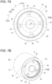
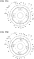
- the unidirectional rotation regulating portion 40 has a function like a unidirectional clutch, and regulates (blocks) the relative rotation of the piston main body 22 with respect to the piston cap 23 in the forward rotation direction (arrow X direction in Figs. 7A , 11A , 11B , 12A, and 12B ), but allows the relative rotation in the reverse rotation direction (arrow Y direction in Figs. 7A , 11A , 11B , 12A, and 12B ).
- the unidirectional rotation regulating portion 40 regulates the relative rotation of the piston main body 22 with respect to the piston cap 23 in the forward rotation direction.
- the spindle 82 is driven to rotate in the reverse rotation direction (during release) to release the braking force of the parking brake, the unidirectional rotation regulating portion 40 allows the relative rotation of the piston main body 22 with respect to the piston cap 23 in the reverse rotation direction.
- the unidirectional rotation regulating portion 40 includes a main body-side engagement portion 41 in the piston main body 22, and includes a cap-side engagement portion 42 in the piston cap 23.
- the main body-side engagement portion 41 and the cap-side engagement portion 42 are mechanically (unreleasably) engaged with each other when the spindle 82 is driven to rotate in the forward rotation direction.
- the main body-side engagement portion 41 is provided on an axially outer surface of the partition wall portion 26 of the piston main body 22. As shown in Figs. 7A, 7B , and 8 , the main body-side engagement portion 41 has a convex shape protruding in the axial direction, and a plurality of (four in the illustrated example) main body-side engagement portions 41 are provided on the radially outer portion of the axially outer surface of the partition wall portion 26 at equal intervals in the circumferential direction. The plurality of main body-side engagement portions 41 are disposed on a concentric circle centered on the central axis O 22 of the piston main body 22.
- each of the main body-side engagement portions 41 has a substantially triangular prism shape, and has a substantially fan shape as viewed in the axial direction and a triangular shape as viewed in the radial direction. Therefore, each of the main body-side engagement portions 41 has an axial height from the axially outer surface of the partition wall portion 26 that varies in the circumferential direction. Specifically, each of the main body-side engagement portions 41 has a shape in which the axial height gradually increases from the rear to the front in the forward rotation direction (arrow X direction in Fig. 7A ) (from the front to the rear in the reverse rotation direction (arrow Y direction in Fig. 7A )). Therefore, in the main body-side engagement portion 41, an axial height of an end portion on the front side in the forward rotation direction is the largest, and an axial height of an end portion on the rear side in the forward rotation direction is the smallest.
- each of the main body-side engagement portions 41 has a main body-side regulating surface 43 on a side surface on the front side in the forward rotation direction.
- the main body-side regulating surface 43 is formed in a flat surface shape, and is disposed parallel to the central axis O 22 of the piston main body 22. That is, the main body-side regulating surface 43 is a right angle surface perpendicular to the axially outer surface of the partition wall portion 26.
- the main body-side regulating surface 43 is disposed on a virtual plane including the central axis O 22 of the piston main body 22.
- each of the main body-side engagement portions 41 has a main body-side guide surface 44 on an axially distal end surface thereof.
- the main body-side guide surface 44 is formed in a flat surface shape, and is an inclined surface linearly inclined in a direction in which the main body-side guide surface 44 is close to the rotor 9 as the main body-side guide surface 44 extends rearward from the front in the reverse rotation direction. That is, the main body-side guide surface 44 is an inclined surface inclined with respect to the axially outer surface of the partition wall portion 26.
- An inclination angle a see Fig.
- the main body-side guide surface 44 comes into contact with a cap-side guide surface 46 to be described later which is provided on the cap-side engagement portion 42.
- the main body-side guide surface 44 and the main body-side regulating surface 43 are connected to each other via a chamfered portion.
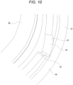
- the cap-side engagement portion 42 is provided on an axially inner end surface of the cylindrical portion 32 of the piston cap 23. As shown in Figs. 9A, 9B , and 10 , the cap-side engagement portion 42 has a convex shape protruding in the axial direction, and a plurality of (four in the illustrated example) cap-side engagement portions 42 are provided on the axially inner end surface of the cylindrical portion 32 at equal intervals in the circumferential direction. The plurality of cap-side engagement portions 42 are disposed on a concentric circle centered on the central axis O 23 of the piston cap 23.
- each of the cap-side engagement portions 42 has substantially the same shape as each of the main body-side engagement portions 41. That is, each of the cap-side engagement portions 42 has a substantially triangular prism shape, and has a substantially fan shape as viewed in the axial direction and a triangular shape as viewed in the radial direction. Therefore, each of the cap-side engagement portions 42 has an axial height from the axially inner end surface of the cylindrical portion 32 that varies in the circumferential direction. Specifically, each of the cap-side engagement portions 42 has a shape in which the axial height gradually increases from the rear to the front in the reverse rotation direction (arrow Y direction in Fig. 9A ) (from the front to the rear in the forward rotation direction (arrow X direction in Fig. 9A )). Therefore, in the cap-side engagement portion 42, an axial height of an end portion on the front side in the reverse rotation direction is the largest, and an axial height of an end portion on the rear side in the reverse rotation direction is the smallest.
- each of the cap-side engagement portions 42 has a cap-side regulating surface 45 on a side surface on the rear side in the forward rotation direction.
- the cap-side regulating surface 45 is formed in a flat surface shape, and is disposed parallel to the central axis O 23 of the piston cap 23. That is, the cap-side regulating surface 45 is a right angle surface perpendicular to the axially inner end surface of the cylindrical portion 32. In the present example, the cap-side regulating surface 45 is disposed on a virtual plane including the central axis O 23 of the piston cap 23.
- each of the cap-side engagement portions 42 has a cap-side guide surface 46 on an axially distal end surface thereof.
- the cap-side guide surface 46 is formed in a flat surface shape, and is an inclined surface linearly inclined in a direction in which the cap-side guide surface 46 is away from the rotor 9 as the cap-side guide surface 46 extends forward from the rear in the reverse rotation direction. That is, the cap-side guide surface 46 is an inclined surface inclined with respect to the axially inner end surface of the cylindrical portion 32.
- An inclination angle ⁇ (see Fig.
- the inclination angle ⁇ of the cap-side guide surface 46 is the same as the inclination angle ⁇ of the main body-side guide surface 44. However, the inclination angle ⁇ may be different from the inclination angle ⁇ .
- the inclination angle ⁇ of the main body-side guide surface 44 and the inclination angle ⁇ of the cap-side guide surface 46 can be determined in consideration of the fact that the frictional force acting on the piston main body 22 by the piston seals 30a and 30b is overcome and the main body-side guide surface 44 rides on the cap-side guide surface 46, and the fact that the main body-side guide surface 44 slips down from the cap-side guide surface 46 during forward rotation driving.
- a sufficiently large play (backlash) in the axial direction between the piston ring 38 and the holding recessed groove 39 is ensured.
- the piston cap 23 is held so as to be displaceable relative to the piston main body 22 in the axial direction as much as the main body-side engagement portion 41 gets over the cap-side engagement portion 42. Therefore, the main body-side engagement portion 41 gets over the cap-side engagement portion 42, and thus the piston main body 22 is allowed to rotate relative to the piston cap 23 in the reverse rotation direction.
- An axial force transmitting portion 47 for transmitting an axial force between the piston main body 22 and the piston cap 23 is further provided between the piston main body 22 and the piston cap 23, separately from the unidirectional rotation regulating portion 40.
- the axial force transmitting portion 47 includes a main body-side transmission surface 48 provided in the piston main body 22 and a cap-side transmission surface 49 provided in the piston cap 23.
- the main body-side transmission surface 48 and the cap-side transmission surface 49 are disposed to face each other in the axial direction.
- the main body-side transmission surface 48 has an annular shape, and is provided radially outward of the main body-side engagement portion 41 on the axially outer surface of the partition wall portion 26 of the piston main body 22.
- the main body-side transmission surface 48 is formed in a flat surface shape, and is disposed on a virtual plane orthogonal to the central axis O 22 of the piston main body 22.
- the cap-side transmission surface 49 has an annular shape, and is provided radially outward of the cap-side engagement portion 42 on the axially inner end surface of the cylindrical portion 32 of the piston cap 23.
- the cap-side transmission surface 49 is formed in a flat surface shape, and is disposed on a virtual plane orthogonal to the central axis O 23 of the piston cap 23.
- the service-dedicated piston 8 has a two-part structure similarly to the dual-purpose piston 7. As shown in Fig. 3 , the service-dedicated piston 8 includes a cylindrical portion 106 made of, for example, carbon steel and having a bottomed cylindrical shape, and a lid portion 107 made of, for example, stainless steel and mounted in a distal end portion of the cylindrical portion 106. A hydraulic chamber 50 for introducing pressure oil is formed between a bottom surface of the service-dedicated piston 8 and a deep portion of each of the cylinders 10a, 10b, and 11b into which the service-dedicated piston 8 is fitted.
- annular piston seal 52 is mounted in a seal groove 51 formed on an inner peripheral surface of each of the cylinders 10a, 10b, and 11b.
- a dust cover 53 is bridged between an opening edge portion of each of the cylinders 10a, 10b, and 11b and a distal end portion of the service-dedicated piston 8.
- the brake oil is fed to hydraulic chambers 28 and 50 of the cylinders 10a, 10b, 11a, and 11b through oil passages 18a and 18b provided in the outer body portion 13 and the inner body portion 14.
- a pressure receiving area of the dual-purpose piston 7 and a pressure receiving area of the service-dedicated piston 8 facing the dual-purpose piston 7 are equal to each other. Therefore, during service braking, the dual-purpose piston 7 and the service-dedicated piston 8 (and other service-dedicated pistons 8) axially opposed to the dual-purpose piston 7 press both axial side surfaces of the rotor 9 with equal forces.
- An opening of the oil passage 18a is closed by a bleeder screw 54.
- a pair of guide wall portions 55a and 55b protruding in the axial direction so as to be close to the rotor 9 are respectively provided on both circumferential side portions of the axially inner surface of the outer body portion 13 and on both circumferential side portions of the axially outer surface of the inner body portion 14.
- the guide wall portion 55a disposed on one side in the circumferential direction is provided with a guide recessed groove 56a that is opened in the axial direction and is opened to the other side in the circumferential direction
- the guide wall portion 55b disposed on the other side in the circumferential direction is provided with a guide recessed groove 56b that is opened in the axial direction and is opened to the one side in the circumferential direction.
- the outer pad 6a and the inner pad 6b are disposed on both sides of the rotor 9 in the axial direction. Specifically, the outer pad 6a is disposed between the rotor 9 and the outer body portion 13, and the inner pad 6b is disposed between the rotor 9 and the inner body portion 14.
- Each of the outer pad 6a and the inner pad 6b includes a lining (friction material) 57 and a metal-made back plate (pressure plate) 58 that supports a back surface of the lining 57.
- the inner pad 6b corresponds to a pad described in the claims.
- Both circumferential side portions of the back plate 58 are provided with ear portions 59 protruding in the circumferential direction.
- the pair of ear portions 59 provided in the outer pad 6a are loosely engaged with the pair of guide recessed grooves 56a and 56b provided in the outer body portion 13, respectively.
- the pair of ear portions 59 provided in the inner pad 6b are loosely engaged with the pair of guide recessed grooves 56a and 56b provided in the inner body portion 14, respectively. Accordingly, the outer pad 6a and the inner pad 6b are supported with respect to the caliper 4 so as to be displaceable in the axial direction and so as not to be displaceable in the circumferential direction and the radial direction.
- a substantially columnar engagement protrusion 35 protruding axially inward is provided on a back surface of the back plate 58 composing the inner pad 6b.
- the engagement recess 34 of the piston cap 23 composing the dual-purpose piston 7 is engaged with the engagement protrusion 35.
- the clamp member 5 composing the floating type brake mechanism 3 is made of an aluminum-based alloy or an iron-based alloy, and has an inverted U-shape.
- the clamp member 5 is disposed on a portion between the rotation-in side coupling portion 15a and the intermediate coupling portion 16 in the circumferential direction, and straddles the pair of pads 6a and 6b and the inner body portion 14 from the radially outer side. That is, the clamp member 5 is mounted on the caliper 4.
- the clamp member 5 has a bifurcated pressing portion 60 in an axially outer portion and a clamp base portion 61 in an axially inner portion.
- the clamp member 5 includes a bridge portion 62 that is disposed on the radially outer side of the rotor 9 and couples the pressing portion 60 and the clamp base portion 61 in the axial direction.
- the pressing portion 60 is inserted from the radially outer side into a portion between an axially inner surface of a half portion of the outer body portion 13 on one side in the circumferential direction and an axially outer surface of a half portion of the outer pad 6a on one side in the circumferential direction so as to straddle the rotation-in side outer cylinder 10a.
- the clamp base portion 61 is disposed axially inside the inner body portion 14, and includes a base body 63 and one arm portion 64 extending from the base body 63 to the other side in the circumferential direction.
- the base body 63 includes an accommodation portion 65 of which is a substantially cylindrical space therein.
- the accommodation portion 65 is opened axially outward, but an opening on the axially inner side is closed by a bottom portion 66.
- the accommodation portion 65 has an inner diameter slightly larger than an outer diameter of the guide cylinder 21 provided in the inner body portion 14.
- a through hole 67 penetrating in the axial direction is provided in a central portion of the bottom portion 66.
- a support cylindrical portion 68 extending in the axial direction is provided at a distal end portion of the arm portion 64.
- the support cylindrical portion 68 is opened on both sides in the axial direction, and a central axis of the support cylindrical portion 68 and a central axis of the accommodation portion 65 provided in the base body 63 are parallel to each other.
- the clamp member 5 as described above is supported so as to be displaceable with respect to the caliper 4 in the axial direction.
- the clamp member 5 is supported with respect to the caliper 4 by a total of three points, a first guide portion 69, a second guide portion 70, and a third guide portion 71.
- the first guide portion 69 includes the guide cylinder 21 provided in the inner body portion 14 and the accommodation portion 65 provided in the clamp base portion 61. That is, the first guide portion 69 is formed by fitting a distal half portion of the guide cylinder 21 inside the accommodation portion 65 so as to be relatively displaceable in the axial direction. In addition, a central axis of the guide cylinder 21 and the central axis of the accommodation portion 65 are disposed coaxially with each other.
- a radial gap between an outer peripheral surface of the guide cylinder 21 and an inner peripheral surface of the accommodation portion 65 is set to such a size that prying does not occur between the outer peripheral surface of the guide cylinder 21 and the inner peripheral surface of the accommodation portion 65 even when the pressing portion 60 and the clamp base portion 61 are axially displaced away from each other during parking braking.
- a seal groove 72 having a substantially rectangular cross-sectional shape is formed in an axially inner portion of the inner peripheral surface of the accommodation portion 65, and an annular seal member 73 is mounted in the seal groove 72.
- the seal member 73 is sandwiched between the outer peripheral surface of the guide cylinder 21 and the inner peripheral surface of the accommodation portion 65, and the guide cylinder 21 is hermetically fitted into the accommodation portion 65.
- a dust cover 74 is bridged between an opening edge portion of the accommodation portion 65 and an axially intermediate portion of the outer peripheral surface of the guide cylinder 21.
- the second guide portion 70 is provided at the same position as the intermediate coupling portion 16 in the circumferential direction, which is deviated from the first guide portion 69 in the circumferential direction, and supports the clamp member 5 together with the first guide portion 69 so as to be displaceable with respect to the caliper 4 in the axial direction.
- the second guide portion 70 includes a support cylindrical portion 68 provided on the arm portion 64 composing the clamp base portion 61, and an inner guide pin 75 fixed to the inner body portion 14.
- the inner guide pin 75 has an axially outer portion fixed to the inner body portion 14, and an axially intermediate portion inserted into the support cylindrical portion 68 so as to be slidable (relatively displaceable) in the axial direction.
- the inner guide pin 75 is bridged in the axial direction between the inner body portion 14 and the support cylindrical portion 68.
- a central axis of the inner guide pin 75 and the central axis of the guide cylinder 21 are disposed parallel to each other.
- the third guide portion 71 is provided at the same position as the first guide portion 69 in the circumferential direction, and supports the clamp member 5 together with the first guide portion 69 and the second guide portion 70 so as to be displaceable with respect to the caliper 4 in the axial direction.
- the third guide portion 71 includes a protruding support portion 76 provided in the outer body portion 13 and an outer guide pin 77 fixed to the clamp member 5.
- the protruding support portion 76 is provided on a radially outer side of the rotation-in side outer cylinder 10a in the outer body portion 13.
- the outer guide pin 77 has an axially inner portion fixed to the pressing portion 60 of the clamp member 5, and an axially outer portion inserted into the protruding support portion 76 so as to be slidable (relatively displaceable) in the axial direction. Therefore, the outer guide pin 77 is bridged in the axial direction between the outer body portion 13 and the pressing portion 60. In addition, a central axis of the outer guide pin 77 and the central axis of the accommodation portion 65 are disposed parallel to each other.
- the electric actuator 12 composing the floating type brake mechanism 3 includes an electric drive device (MGU) 78 disposed axially inside the clamp base portion 61, and a rotary-to-linear motion conversion mechanism 79 disposed inside the accommodation portion 65.
- MGU electric drive device
- the electric drive device 78 includes a casing 80, and an electric motor as a drive source and a speed reduction mechanism such as a gear type speed reducer, which are accommodated inside the casing 80.
- a rotation shaft 81 to which a final gear composing the speed reduction mechanism is fixed is inserted into the through hole 67 formed in the bottom portion 66 of the clamp base portion 61.
- the rotary-to-linear motion conversion mechanism 79 is a feed screw mechanism that converts a rotary motion into a linear motion and changes an entire length in the axial direction during operation, and includes the spindle 82 corresponding to a rotary member described in the claims and a nut 83 corresponding to a linear motion member described in the claims.
- the spindle 82 has a male screw portion 84 on an outer peripheral surface ranging from a distal end portion (axially outer portion) to an intermediate portion.
- a flange portion 85 having a larger diameter than other portions is provided at a portion of the spindle 82 near a proximal end.
- a proximal end portion (axially inner portion) of the spindle 82 is rotatably supported inside the through hole 67 formed in the bottom portion 66 of the clamp base portion 61, and is connected to a distal end portion of the rotation shaft 81 so as not to be rotatable relative to the distal end portion of the rotation shaft 81. Therefore, the spindle 82 can be rotationally driven by the electric motor.
- the distal end portion of the spindle 82 is inserted into the dual-purpose piston 7 from the axially inner side.
- a central axis of the spindle 82 is coaxial with the central axis of the accommodation portion 65 (guide cylinder 21).
- a thrust bearing 86 is disposed between an axially inner surface of the flange portion 85 and an axially outer surface of the bottom portion 66. Accordingly, an axial load acting on the flange portion 85 can be supported by the bottom portion 66, and the flange portion 85 can rotate with respect to the bottom portion 66.
- the nut 83 has a female screw portion 87 on an inner peripheral surface thereof, and is screwed to the male screw portion 84 provided on the spindle 82.
- a male spline 88 having a larger diameter than other portions is provided at a distal end portion (axially outer portion) of the nut 83.
- the male spline 88 is spline-engaged with the female spline 29 formed on the inner peripheral surface of the small diameter cylindrical portion 25. Therefore, the nut 83 is engaged with the dual-purpose piston 7 so as to be relatively displaceable in the axial direction and so as not to be relatively rotatable.
- the nut 83 is movable in the axial direction by rotating the spindle 82. Specifically, when the spindle 82 is driven to rotate in the forward rotation direction, the nut 83 moves toward the rotor 9 and presses the piston main body 22 in the axial direction, whereas when the spindle 82 is driven to rotate in the reverse rotation direction, the nut 83 moves toward the side opposite to the rotor 9.
- the brake oil is fed to the hydraulic chambers 28 and 50 of all the cylinders 10a, 10b, 11a, and 11b provided in the caliper 4 through the oil passages 18a and 18b. Accordingly, all the pistons 7 and 8 (one dual-purpose piston 7 and three service-dedicated pistons 8) are pushed out from the cylinders 10a, 10b, 11a, and 11b, and the pair of pads 6a and 6b are pressed against both axial side surfaces of the rotor 9. As a result, the rotor 9 is strongly pressed from both sides in the axial direction to perform braking. In this way, the disc brake device 1 obtains the braking force of the service brake by pushing out all the pistons 7 and 8 by introducing the brake oil.
- the electric motor composing the electric drive device 78 is energized, and the spindle 82 composing the rotary-to-linear motion conversion mechanism 79 is driven to rotate in the forward rotation direction.
- a torque in the forward rotation direction acts on the piston main body 22 from the nut 83. Therefore, the piston main body 22 tends to rotate relative to the piston cap 23 in the forward rotation direction.
- the piston seal 30a (30b) is sandwiched between the piston main body 22 and the rotation-in side inner cylinder 11a, the rotation of the piston main body 22 is regulated by the frictional force acting between the piston main body 22 and the piston seal 30a (30b).
- the nut 83 and the piston main body 22 do not rotate, and the nut 83 is moved axially outward with respect to the inner body portion 14.
- the distal end portion of the nut 83 is pressed against the axially inner surface of the partition wall portion 26 of the dual-purpose piston 7, and the dual-purpose piston 7 is pushed out toward the rotor 9, and thus the inner pad 6b is pressed against the axially inner surface of the rotor 9.
- a reaction force caused by the pressing is transmitted from the spindle 82 to the clamp member 5 via the thrust bearing 86. Accordingly, the spindle 82 and the clamp member 5 are displaced axially inward with respect to the caliper 4.
- the guide cylinder 21 and the accommodation portion 65 (first guide portion 69), the inner guide pin 75 and the support cylindrical portion 68 (second guide portion 70), and the outer guide pin 77 and the protruding support portion 76 (third guide portion 71) slide in the axial direction.
- the outer pad 6a is pressed against the axially outer surface of the rotor 9 by the pressing portion 60 of the clamp member 5.
- the rotor 9 is sandwiched from both sides in the axial direction by the pair of pads 6a and 6b, and the braking force is obtained.
- the disc brake device 1 obtains the braking force of the parking brake by pushing out the dual-purpose piston 7 using the electric actuator 12 and displacing the clamp member 5 axially inward with respect to the caliper 4.
- the spindle 82 is driven to rotate in the reverse rotation direction by the electric motor composing the electric drive device 78.
- a torque in the reverse rotation direction acts on the piston main body 22 from the nut 83. Therefore, the piston main body 22 tends to rotate relative to the piston cap 23 in the reverse rotation direction.
- the rotation of the piston main body 22 is regulated by the frictional force acting between the piston main body 22 and the piston seal 30a (30b) as long as the torque acting on the piston main body 22 from the nut 83 does not excessively increase as in the case where the nut 83 and the spindle 82 are in a locked state.
- the nut 83 is displaced axially inward with respect to the inner body portion 14.
- the clamp member 5 is displaced axially outward with respect to the inner body portion 14 by displacing the spindle 82 axially outward with respect to the inner body portion 14.
- the guide cylinder 21 and the accommodation portion 65, the inner guide pin 75 and the support cylindrical portion 68, and the outer guide pin 77 and the protruding support portion 76 slide in the axial direction.
- the disc brake device 1 of the present example it is possible to stably obtain the braking force of the parking brake while preventing the temperature rise of the brake oil accommodated in the hydraulic chamber 28 of the rotation-in side inner cylinder 11a, and it is possible to solve the problem caused when the nut 83 is fully released to the side opposite to the rotor 9.
- the dual-purpose piston 7 has a two-part structure including the piston main body 22 and the piston cap 23. Therefore, even in a case where the inner pad 6b heats up when pressed against the rotating rotor 9, in the present example in which the dual-purpose piston 7 is used, the amount of heat transferred to the brake oil accommodated in the hydraulic chamber 28 can be reduced as compared with the case where the piston has an integrated structure.
- the hydraulic chamber 28 can be away from the inner pad 6b. Therefore, it is possible to prevent an increase in temperature of the brake oil. As a result, deterioration of the brake oil can be prevented, and occurrence of a vapor lock phenomenon can be prevented.
- the unidirectional rotation regulating portion 40 is disposed between the piston main body 22 and the piston cap 23 composing the dual-purpose piston 7, it is possible to prevent the piston main body 22 and the piston cap 23 from rotating relative to each other even when a sufficient frictional force cannot be obtained by the piston seal 30a (30b).
- the main body-side engagement portion 41 and the cap-side engagement portion 42 can be mechanically engaged with each other by allowing the main body-side regulating surface 43, which is the right angle surface of the main body-side engagement portion 41 provided in the piston main body 22, to come into surface contact with the cap-side regulating surface 45, which is the right angle surface of the cap-side engagement portion 42 provided in the piston cap 23. Therefore, it is possible to regulate the relative rotation of the piston main body 22 with respect to the piston cap 23 in the forward rotation direction. Therefore, the braking force of the parking brake can be stably obtained.
- the engagement protrusion 35 provided in the inner pad 6b is engaged with the engagement recess 34 provided in the piston cap 23 to prevent the piston cap 23 from rotating. Therefore, as compared with the case where the frictional force acting between the piston cap and the inner pad is used to prevent rotation, the rotation can be reliably prevented, and the braking force can be more stably obtained.
- the main body-side guide surface 44 which is the inclined surface of the main body-side engagement portion 41 provided in the piston main body 22, comes into contact with the cap-side guide surface 46, which is the inclined surface of the cap-side engagement portion 42 provided in the piston cap 23.
- the piston cap 23 including the cap-side engagement portion 42 is held so as to be displaceable relative to the piston main body 22 in the axial direction by using the piston ring 38, and the displacement to the axially outer side is regulated by the rotor 9. Therefore, the cap-side guide surface 46 can push up the main body-side guide surface 44 in the axial direction (move the main body-side guide surface 44 to the side opposite to the rotor 9) by using the inclination.
- a sufficiently large play (backlash) in the axial direction between the piston ring 38 and the holding recessed groove 39 is ensured as much as the main body-side engagement portion 41 gets over the cap-side engagement portion 42. Therefore, the piston main body 22 is allowed to rotate (displace) not only about several degrees but also to completely rotate relative to the piston cap 23 as the main body-side engagement portion 41 rides on the cap-side engagement portion 42. Therefore, damage to the electric motor and the speed reduction mechanism can be effectively prevented.
- the piston main body 22 can be rotated with respect to the piston cap 23 in the reverse rotation direction. Therefore, it is possible to prevent a torque from acting on the piston boot 36 that is bridged between the piston cap 23 and the opening edge portion of the rotation-in side inner cylinder 11a. Accordingly, damage to the piston boot 36 can be prevented.
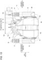
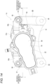
- a second example of the embodiment will be described with reference to Figs. 13 to 16 .
- the same components as those of the first example of the embodiment are denoted by the same reference numerals as those of the first example of the embodiment, and a detailed description thereof will be omitted.
- a disc brake device 1a of the present example is an electric parking brake type disc brake device, and has both a function of a hydraulic service brake and a function of an electric parking brake.
- the disc brake device 1a includes a support 89, a caliper 4a, a pair of pads 6c and 6d (outer pad 6c and inner pad 6d), one piston 90, and the electric actuator 12.
- the support 89 is a cast product of an iron-based alloy such as cast iron, and includes a support base portion 91 disposed on an axially inner side of the rotor 9 (see Fig. 15 ), an outer coupling portion 92 disposed on an axially outer side of the rotor 9, and a pair of coupling arm portions 93 that respectively couple end portions on both sides in a circumferential direction of the support base portion 91 and end portions on both sides in a circumferential direction of the outer coupling portion 92 in the axial direction.
- the support 89 is fixed to a suspension device using a pair of attachment holes 94 formed in a radially inner portion of the support base portion 91.
- a guide hole (not shown) that is opened axially inward is formed in a radially outer portion (rotor path portion) of each of the coupling arm portions 93.
- the outer pad 6c is disposed on an axially outer side of the rotor 9, and is supported so as to be displaceable with respect to the support 89 in the axial direction.
- the inner pad 6d is disposed on an axially inner side of the rotor 9, and is supported so as to be displaceable with respect to the support 89 in the axial direction.
- the caliper 4a is made of an aluminum-based alloy or an iron-based alloy and has an inverted U-shape.
- the caliper 4a has a bifurcated pressing portion 60a in an axially outer portion and a clamp base portion 61a in an axially inner portion.
- the caliper 4a includes a bridge portion 62a that is disposed on the radially outer side of the rotor 9 and couples the pressing portion 60a and the clamp base portion 61a in the axial direction.
- the clamp base portion 61a includes a base body 63a and a pair of arm portions 64a that extend from the base body 63a to both sides in the circumferential direction.
- the base body 63a has a cylinder 95 of which is a substantially cylindrical space therein.
- the cylinder 95 is opened axially outward, but an opening on the axially inner side is closed by a bottom portion 66a.
- the caliper 4a as described above is supported so as to be displaceable with respect to the support 89 in the axial direction. For this reason, axially inner end portions of a guide pin 96 are fixed to the pair of arm portions 64a that composing the clamp base portion 61a, and the end portions or an intermediate portion of the guide pin 96 on an axially inner side are inserted into guide holes formed in the pair of coupling arm portions 93 that compose the support 89 so as to be relatively displaceable in the axial direction. In addition, a boot 97 is bridged between an outer peripheral surface of the guide pin 96 and an opening of the guide hole.
- the piston 90 has a divided structure divided into two parts in the axial direction.
- the piston 90 includes a piston main body 22a and a piston cap 23a.
- the piston main body 22a is made of a metal such as carbon steel, has a bottomed cylindrical shape, and is fitted to the cylinder 95.
- the piston main body 22a includes a partition wall portion 26a having a substantially disc shape.
- the partition wall portion 26a is disposed in an axially intermediate portion of the piston main body 22a, and partitions the inside of the piston main body 22a in the axial direction.
- a female spline 29a is provided axially inward of the partition wall portion 26a on an inner peripheral surface of the piston main body 22a.
- a portion between the piston main body 22a and the cylinder 95 is sealed by an annular piston seal 30c.
- the piston seal 30c is mounted in a seal groove 31c formed in an inner peripheral surface of an axially outer portion of the cylinder 95.
- the piston cap 23a is made of, for example, stainless steel, titanium, or synthetic resin, includes a cylindrical portion 32a and a closing plate portion 33a, and is formed in a bottomed cylindrical shape.
- an axially inner portion of the cylindrical portion 32a is disposed inside the piston main body 22a, and an axially outer portion of the cylindrical portion 32a is prevented from rotating with respect to the inner pad 6d.
- a piston boot 36a is bridged between the cylindrical portion 32a of the piston cap 23a and an axially outer opening edge portion of the cylinder 95.
- a piston ring 38a is externally fitted to a portion of the cylindrical portion 32a of the piston cap 23a disposed inside the piston main body 22a.
- the piston ring 38a has a circular cross-sectional shape, and a radially outer portion thereof is engaged with a holding recessed groove 39a having a substantially rectangular cross-sectional shape provided on an inner peripheral surface of an axially outer portion of the piston main body 22a so as to be displaceable in the axial direction.
- the piston main body 22a and the piston cap 23a are connected to each other via the unidirectional rotation regulating portion 40 having the same configuration as that of the first example of the embodiment described above. Therefore, on the axially outer surface of the partition wall portion 26a of the piston main body 22a, the main body-side engagement portions 41 (see Figs. 7A and 7B , and the like) each having a convex shape are disposed at equal intervals in the circumferential direction, and on the axially inner end surface of the cylindrical portion 32a of the piston cap 23a, the cap-side engagement portions 42 (see Figs. 9A and 9B , and the like) each having a convex shape are disposed at equal intervals in the circumferential direction.
- the axial force transmitting portion 47 for transmitting an axial force between the piston main body 22a and the piston cap 23a is further provided between the piston main body 22 and the piston cap 23, separately from the unidirectional rotation regulating portion 40. Therefore, the annular main body-side transmission surface 48 is provided radially outward of the main body-side engagement portion 41 on the axially outer surface of the partition wall portion 26a of the piston main body 22a, and the annular cap-side transmission surface 49 is provided radially outward of the cap-side engagement portion 42 on the axially inner end surface of the cylindrical portion 32a of the piston cap 23a.
- the electric actuator 12 has the same configuration as that of the first example of the embodiment, and includes the electric drive device 78 disposed axially inside the clamp base portion 61a, and the rotary-to-linear motion conversion mechanism 79 disposed inside the cylinder 95.
- the rotation shaft 81 composing the electric drive device 78 is inserted into a through hole 67a formed in a bottom portion 66a of the clamp base portion 61a, and a proximal end portion of the spindle 82 composing the rotary-to-linear motion conversion mechanism 79 is connected to the distal end portion of the rotation shaft 81 so as not to be rotatable relative to the distal end portion of the rotation shaft 81.
- the male spline 88 formed on the outer peripheral surface is spline-engaged with a female spline 29a formed on an inner peripheral surface of the piston 90. Accordingly, the nut 83 is disposed inside the piston 90 so as to be displaceable in the axial direction and so as not to be relatively rotatable.
- brake oil is fed to the hydraulic chamber 98 of the cylinder 95 provided in the caliper 4a through an oil passage (not shown). Accordingly, the piston 90 is pushed out from the cylinder 95, and the inner pad 6d is pressed against the axially inner surface of the rotor 9.
- a reaction force caused by the pressing is transmitted from the spindle 82 to the caliper 4a via the thrust bearing 86. Accordingly, the caliper 4a is displaced axially inward with respect to the support 89.
- the outer pad 6c is pressed against the axially outer surface of the rotor 9 by the pressing portion 60a of the caliper 4a.
- the rotor 9 is strongly pressed from both sides in the axial direction to perform braking. In this way, the disc brake device 1 obtains the braking force of the service brake by pushing out the piston 90 by introducing the brake oil.
- the electric motor composing the electric drive device 78 is energized, and the spindle 82 is driven to rotate in the forward rotation direction. Accordingly, the nut 83 is displaced axially outward with respect to the support 89. The distal end portion of the nut 83 is pressed against the axially inner surface of the partition wall portion 26a of the piston main body 22a, and the piston 90 is pushed out toward the rotor 9, and thus the inner pad 6d is pressed against the axially inner surface of the rotor 9.
- a reaction force caused by the pressing is transmitted from the spindle 82 to the caliper 4a via the thrust bearing 86. Accordingly, the caliper 4a is displaced axially inward with respect to the support 89.
- the outer pad 6c is pressed against the axially outer surface of the rotor 9 by the pressing portion 60a of the caliper 4a. Accordingly, the rotor 9 is sandwiched from both sides in the axial direction, and the braking force is obtained.
- the disc brake device 1a obtains the braking force of the parking brake by pushing out the piston 90 using the electric actuator 12 and displacing the caliper 4a axially inward with respect to the support 89.
- the unidirectional rotation regulating portion 40 is provided between the piston main body 22a and the piston cap 23a, it is possible to prevent the piston main body 22a from rotating with respect to the piston cap 23a in the forward rotation direction even when a sufficient frictional force cannot be obtained by the piston seal 30c. Therefore, the braking force of the parking brake can be stably obtained.
- the spindle 82 In order to release the parking brake, the spindle 82 is driven to rotate in the reverse rotation direction. Accordingly, the nut 83 is displaced axially inward with respect to the support 89. In addition, the caliper 4a is displaced axially outward with respect to the support 89 by displacing the spindle 82 axially outward with respect to the support 89. At this time, the outer peripheral surfaces of the pair of guide pins 96 and the inner peripheral surfaces of the pair of guide holes slide in the axial direction.
- the unidirectional rotation regulating portion 40 is provided between the piston main body 22a and the piston cap 23a, it is possible to allow the piston main body 22a to rotate with respect to the piston cap 23a in the reverse rotation direction even when the nut 83 is fully released to the side opposite to the rotor 9 due to malfunction of the electric motor or the like. Therefore, it is possible to effectively prevent a decrease in durability of the electric motor and the speed reduction mechanism composing the electric drive device 78.
- the piston 90 has a two-part structure including the piston main body 22a and the piston cap 23a, and the piston main body 22a and the piston cap 23a are connected to each other via the unidirectional rotation regulating portion 40, and thus, it is possible to stably obtain the braking force of the parking brake while preventing the temperature rise of the brake oil, and it is possible to solve the problem caused when the nut 83 is fully released to the side opposite to the rotor 9.
- a third example of the embodiment will be described with reference to Figs. 17A to 18B .
- the same components as those of the first example of the embodiment are denoted by the same reference numerals as those of the first example of the embodiment, and a detailed description thereof will be omitted.
- the present example is a modification of the first example of the embodiment, and a structure of a unidirectional rotation regulating portion 40a provided between a piston main body 22b and a piston cap 23b composing the dual-purpose piston 7 (see Figs. 6A and 6B , and the like) is changed from the structure of the first example of the embodiment.
- the unidirectional rotation regulating portion 40a of the present example not only has a function of regulating the relative rotation of the piston main body 22b with respect to the piston cap 23b in the forward rotation direction (arrow X direction in Figs. 17A and 18A ) and allowing the relative rotation in the reverse rotation direction (arrow Y direction in Figs. 17A and 18A ), but also has a function of transmitting an axial force between the piston main body 22b and the piston cap 23b.
- the unidirectional rotation regulating portion 40a includes a main body-side sliding contact surface 99 provided on an axially outer surface of a partition wall portion 26b composing the piston main body 22b, and a cap-side sliding contact surface 100 provided on an axially inner end surface of a cylindrical portion 32b composing the piston cap 23b.
- the main body-side sliding contact surface 99 and the cap-side sliding contact surface 100 are disposed to face each other in the axial direction.
- the main body-side sliding contact surface 99 is formed in a flat surface shape, and is disposed on a virtual plane orthogonal to a central axis of the piston main body 22b.
- the main body-side sliding contact surface 99 has an annular shape, and is subjected to surface processing for increasing a friction coefficient between the main body-side sliding contact surface 99 and the cap-side sliding contact surface 100.
- the main body-side sliding contact surface 99 is subjected to a surface roughening process, and is a rough surface having a larger surface roughness than the other portions of the partition wall portion 26b.
- the cap-side sliding contact surface 100 is formed in a flat surface shape, and is disposed on a virtual plane orthogonal to a central axis of the piston cap 23b.
- the cap-side sliding contact surface 100 has an annular shape, and includes a friction member in order to increase a friction coefficient between the main body-side sliding contact surface 99 and the cap-side sliding contact surface 100.
- the cap-side sliding contact surface 100 is made of an elastic material such as rubber.
- the nut 83 (see Fig. 3 and the like) is moved axially outward to press the distal end portion of the nut 83 against an axially inner surface of the partition wall portion 26b of the piston main body 22b, similarly to the structure of the first example of the embodiment.
- the dual-purpose piston 7 is pushed out toward the rotor 9 (see Fig. 2 ), and the inner pad 6b (see Fig. 3 and the like) is pressed against the axially inner surface of the rotor 9.
- a reaction force caused by the pressing is transmitted from the spindle 82 to the clamp member 5 (see Fig. 3 and the like). Accordingly, the spindle 82 and the clamp member 5 are displaced axially inward with respect to the caliper 4 (see Fig. 3 and the like).
- the outer pad 6a is pressed against the axially outer surface of the rotor 9 by the clamp member 5. Accordingly, the rotor 9 is sandwiched from both sides in the axial direction by the pair of pads 6a and 6b, and the braking force is obtained.
- the unidirectional rotation regulating portion 40a is provided between the piston main body 22b and the piston cap 23b, it is possible to prevent the piston main body 22b from rotating with respect to the piston cap 23b in the forward rotation direction even when a sufficient frictional force cannot be obtained by the piston seal 30a (see Fig. 3 ).
- an axial force acting on the cap-side sliding contact surface 100 from the main body-side sliding contact surface 99 is increased by sandwiching the rotor 9 from both sides in the axial direction by the pair of pads 6a and 6b, the main body-side sliding contact surface 99 and the cap-side sliding contact surface 100 can be frictionally engaged with each other so as not to be relatively rotatable. Therefore, it is possible to prevent the piston main body 22b from rotating with respect to the piston cap 23b in the forward rotation direction, and it is possible to stably obtain the braking force of the parking brake.
- the distal end portion of the nut 83 is separated from the axially inner surface of the partition wall portion 26b of the dual-purpose piston 7, or a force with which the distal end portion of the nut 83 presses the partition wall portion 26b is reduced. Accordingly, the axial force acting on the cap-side sliding contact surface 100 from the main body-side sliding contact surface 99 is reduced, and thus the main body-side sliding contact surface 99 can be rotated relative to the cap-side sliding contact surface 100 in the reverse rotation direction. Therefore, the piston main body 22b can be allowed to rotate with respect to the piston cap 23b in the reverse rotation direction. Therefore, it is possible to effectively prevent a decrease in durability of the electric motor and the speed reduction mechanism.
- the dual-purpose piston 7 has a two-part structure including the piston main body 22b and the piston cap 23b, and the piston main body 22b and the piston cap 23b are connected to each other via the unidirectional rotation regulating portion 40a having the functions as described above. Therefore, it is possible to stably obtain the braking force of the parking brake while preventing the temperature rise of the brake oil, and it is possible to solve the problem caused when the nut 83 is fully released to the side opposite to the rotor 9. In addition, since it is unnecessary to separately provide a power transmitting portion, it is advantageous in reducing the size and weight of the piston main body 22b and the piston cap 23b.
- a fourth example of the embodiment will be described with reference to Fig. 19 .
- the same components as those of the first example of the embodiment are denoted by the same reference numerals as those of the first example of the embodiment, and a detailed description thereof will be omitted.
- the present example is a modification of the first example of the embodiment, and only a structure of a piston cap 23c composing the dual-purpose piston 7 (see Figs. 6A and 6B , and the like) is changed from the structure of the first example of the embodiment.
- the piston cap 23c includes a cap body 101 made of synthetic resin and a plurality of engagement pieces 102 made of metal.
- the cap body 101 includes a cylindrical portion 32c and a closing plate portion 33b.
- Each of the engagement pieces 102 includes a substantially cylindrical base portion 103 and a substantially triangular prism-shaped cap-side engagement portion 42a.
- the base portion 103 is fixed to an axially inner portion of the cylindrical portion 32c of the cap body 101 by molding.
- the cap-side engagement portion 42a has the same configuration as that of the first example of the embodiment, and includes a cap-side regulating surface 45a that is perpendicular to an axially inner end surface of the cylindrical portion 32c, and a cap-side guide surface 46a that is an inclined surface inclined with respect to the axially inner end surface of the cylindrical portion 32c.
- the piston cap 23c since most of the piston cap 23c is made of synthetic resin, the amount of heat transferred to the brake oil accommodated in the hydraulic chamber 28 (see Fig. 3 ) can be reduced as compared with the case where the piston cap is made of metal. Therefore, it is possible to effectively prevent an increase in temperature of the brake oil. Furthermore, since the cap-side engagement portion 42a is made of metal, the amount of wear and deformation of the cap-side engagement portion 42a can be reduced as compared with the case where the cap-side engagement portion 42a is made of synthetic resin.
- the engagement piece may include a metal pin having a cylindrical shape as a whole, a base half portion of the pin may be fixed to the cap body by molding, and a distal half portion of the pin may function as a cap-side engagement portion.
- a cap-side engagement portion 42c similarly to a cap-side engagement portion 42c (see Figs.
- the cap-side engagement portion including the distal half portion of the pin has a cap-side regulating surface on a side surface on the rear side in the forward rotation direction, but does not include a cap-side guide surface, and has a configuration in which a corner portion (including a chamfered portion) is provided between a side surface on the rear side in the reverse rotation direction and an axially distal end surface.
- a fifth example of the embodiment will be described with reference to Fig. 20 .
- the same components as those of the first example of the embodiment are denoted by the same reference numerals as those of the first example of the embodiment, and a detailed description thereof will be omitted.
- the present example is a modification of the first example and the fourth example of the embodiment, and a structure of a piston cap 23d is changed from the structure of the first example of the embodiment.
- the piston cap 23d has a configuration in which an axial force transmitting member 104 made of metal is further provided in the piston cap 23c (see Fig. 19 ) of the fourth example of the embodiment.
- the axial force transmitting member 104 has a substantially cylindrical shape, and is fixed to the cylindrical portion 32c of the cap body 101 by molding. An axially inner end surface of the axial force transmitting member 104 is exposed to an axially inner end surface of the cylindrical portion 32c, and the exposed end surface serves as a cap-side transmission surface 49a. In addition, an axially outer end surface of the axial force transmitting member 104 is also exposed to an axially outer end surface of the cylindrical portion 32c.
- An axially inner portion of the axial force transmitting member 104 is exposed to an outer peripheral surface of the cylindrical portion 32c, and the holding recessed groove 39a is provided in the portion.
- An axially outer portion of the axial force transmitting member 104 is molded inside the cylindrical portion 32c.
- the axial force transmitting member 104 and the plurality of engagement pieces 102 are separated, but the power transmitting member and the plurality of engagement pieces may be integrally configured or fixed to each other.
- the axial force transmitting member 104 made of metal is provided inside the cap body 101 made of synthetic resin, an axial force acting on the piston cap 23d can be transmitted via the axial force transmitting member 104. Therefore, strength of the piston cap 23d can be improved, and durability of the piston cap 23d can be improved.
- FIG. 21A and 21B A sixth example of the embodiment will be described with reference to Figs. 21A and 21B .
- the same components as those of the first example of the embodiment are denoted by the same reference numerals as those of the first example of the embodiment, and a detailed description thereof will be omitted.
- the present example is a modification of the first example of the embodiment, and a structure of a cap-side engagement portion 42b is changed from the structure of the first example of the embodiment.
- a plurality of cap-side engagement portions 42b are provided on an axially inner end surface of a cylindrical portion 32d of a piston cap 23e.
- Each of the cap-side engagement portions 42b has a concave shape recessed in the axial direction, and the plurality of cap-side engagement portions 42b are provided on the axially inner end surface of the cylindrical portion 32d at equal intervals in the circumferential direction.
- the plurality of cap-side engagement portions 42b are disposed on a concentric circle centered on a central axis of the piston cap 23e.
- Each of the cap-side engagement portions 42b has a shape recessed in a substantially triangular prism shape, and an axial depth from the axially inner end surface of the cylindrical portion 32d varies in the circumferential direction.
- each of the cap-side engagement portions 42b has a shape in which the axial depth gradually increases from the rear to the front in the forward rotation direction (arrow X direction in Figs. 21A and 21B ) (from the front to the rear in the reverse rotation direction (arrow Y direction in Figs. 21A and 21B )). Therefore, in the cap-side engagement portion 42b, an axial depth of an end portion on the front side in the forward rotation direction is the largest, and an axial depth of an end portion on the rear side in the forward rotation direction is the smallest.
- Each of the cap-side engagement portions 42b has a cap-side regulating surface 45b on a side surface on the front side in the forward rotation direction.
- the cap-side regulating surface 45b is formed in a flat surface shape, and is disposed parallel to the central axis of the piston cap 23e. That is, the cap-side regulating surface 45b is a right angle surface perpendicular to the axially inner end surface of the cylindrical portion 32d. In the present example, the cap-side regulating surface 45b is disposed on a virtual plane including the central axis of the piston cap 23e.
- Each of the cap-side engagement portions 42b has a cap-side guide surface 46b on an axial bottom surface thereof.
- the cap-side guide surface 46b is formed in a flat surface shape, and is an inclined surface linearly inclined in a direction in which the cap-side guide surface 46b is away from the rotor 9 as the cap-side guide surface 46b extends forward from the rear in the reverse rotation direction. That is, the cap-side guide surface 46b is an inclined surface inclined with respect to the axially inner end surface of the cylindrical portion 32d.
- the main body-side engagement portion 41 can be disposed inside the cap-side engagement portion 42b, it is advantageous in terms of shortening an axial dimension of the dual-purpose piston 7.
- each of the main body-side engagement portions may have a concave shape recessed in the axial direction, and each of the cap-side engagement portions may have a convex shape protruding in the axial direction.
- a seventh example of the embodiment will be described with reference to Figs. 22A and 22B .
- the same components as those of the first example of the embodiment are denoted by the same reference numerals as those of the first example of the embodiment, and a detailed description thereof will be omitted.
- the present example is a modification of the first example of the embodiment, and structures of a main body-side engagement portion 41b and a cap-side engagement portion 42c are changed from the structure of the first example of the embodiment.
- Each of the main body-side engagement portions 41b has a substantially fan shape as viewed in the axial direction, and has a substantially quadrant shape as viewed in the radial direction. Therefore, each of the main body-side engagement portions 41b has an axial height from a partition wall portion 26c that varies in the circumferential direction.
- Each of the main body-side engagement portions 41b has a main body-side regulating surface 43a on a side surface on the front side in the forward rotation direction, and has a main body-side guide surface 44b on an axially distal end surface.
- the main body-side guide surface 44b is a curved surface (partially cylindrical surface) curved in a direction in which the main body-side guide surface 44b is close to the rotor 9 as the main body-side guide surface 44b extends rearward from the front in the reverse rotation direction.
- Each of the cap-side engagement portions 42c has a substantially rectangular parallelepiped shape, and has a substantially fan shape as viewed in the axial direction and a rectangular shape as viewed in the radial direction. Therefore, each of the cap-side engagement portions 42c has an axial height from an axially inner end surface of a cylindrical portion 32e that is constant in the circumferential direction.
- Each of the cap-side engagement portions 42c has a cap-side regulating surface 45c on a side surface on the rear side in the forward rotation direction.
- an axially distal end surface of the cap-side engagement portion 42c is a flat surface parallel to the axially inner end surface of the cylindrical portion 32e, and a cap-side guide surface is not provided.
- Each of the cap-side engagement portions 42c has a corner portion (including a chamfered portion) 105 between a side surface on the rear side in the reverse rotation direction and the axially distal end surface.
- each of the main body-side engagement portions may have a structure including a corner portion instead of the main body-side guide surface, and each of the cap-side engagement portions may have a structure including a cap-side guide surface that is a curved surface.
- one of the main body-side engagement portion and the cap-side engagement portion may have a structure including a corner portion, and the other may have a structure including an inclined surface as a guide surface.
- one of the main body-side engagement portion and the cap-side engagement portion may have a shape with a curved guide surface, and the other may have a structure including an inclined guide surface.
- the present invention is not limited to the embodiment, and for example, the shapes and the numbers of the convex or concave main body-side engagement portions and cap-side engagement portions composing the unidirectional rotation regulating portion, the surface properties of the main body-side sliding contact surface and the cap-side sliding contact surface composing the unidirectional rotation regulating portion, the type of the friction member, and the like can be appropriately changed.
- the disc brake device of the present invention it is possible to implement a disc brake device that can stably obtain a braking force of a parking brake while preventing a temperature rise of brake oil, and can solve a problem caused when a linear motion member is fully released to a side opposite to a rotor.
Landscapes
- Engineering & Computer Science (AREA)
- General Engineering & Computer Science (AREA)
- Mechanical Engineering (AREA)
- Transportation (AREA)
- Braking Arrangements (AREA)
Abstract
Description
- The present invention relates to a disc brake device.
- Since a disc brake device is excellent in heat dissipation and can finely adjust a braking force during traveling, the number of cases in which the disc brake device is adopted not only for front wheels of an automobile but also for rear wheels of the automobile is increased.
- The disc brake device can be roughly divided into a hydraulic disc brake device that uses hydraulic oil to obtain a braking force and an electric disc brake device that uses an actuator that can be electrically driven to obtain a braking force.
- As an electric disc brake device, as disclosed in
JP2018-184093A - In an electric parking brake type disc brake device, the brake oil is accommodated in the cylinder, and thus, a pad heats up when pressed against a rotating rotor, heat is transferred to the brake oil via a piston, and the temperature of the brake oil is likely to rise. When the temperature of the brake oil rises, deterioration of the brake oil is caused, which causes a vapor lock phenomenon.
- Therefore, in order to make it difficult for heat to be transferred from the pad to the brake oil, the piston may be used as a divided structure as disclosed in
JP2015-25550A -
- Patent Literature 1:
JP2018-184093A - Patent Literature 2:
JP2015-25550A - In the structure described in
JP2015-25550A - That is, in a case where a rotary-to-linear motion conversion mechanism including a spindle as a rotary member and a nut as a linear motion member is used as the electric actuator, when the spindle is driven to rotate in a forward rotation direction to obtain a braking force of the parking brake, a slip may occur between the piston cap and the piston main body on which a torque is applied from a nut, and the piston main body may idle together with the nut. Therefore, it is difficult to stably obtain the braking force of the parking brake.
- In order to solve the above problem, it is conceivable to couple the piston main body and the piston cap so as not to be rotatable relative to each other. By adopting such a configuration, when the spindle is driven to rotate in the forward rotation direction, it is possible to prevent idling of the piston main body and the nut, and it is possible to stably obtain the braking force of the parking brake.
- However, when the spindle is driven to rotate in a reverse rotation direction to release the braking force of the parking brake, the nut is moved (fully released) to a limit position on a side opposite to a rotor, so that the nut and the spindle are brought into a locked state (that is, the nut cannot be further moved in an axial direction along with rotation of the spindle, and the nut is brought into a state of being forcibly rotated together with the spindle). When the nut and the spindle are brought into a locked state, an electric motor as a drive source may reach a stall torque (maximum current). That is, when the nut and the spindle are brought into a locked state, the torque acting on the piston main body from the nut rapidly increases, whereas the rotation of the piston main body is regulated by the piston cap and the piston main body does not rotate, and thus the spindle rapidly stops and the electric motor tends to reach the stall torque. Therefore, the durability of the electric motor tends to decrease. In addition, when a speed reduction mechanism such as a gear type speed reducer is provided between the electric motor and the spindle, a torque acting on the speed reduction mechanism excessively increases, and the durability of the speed reduction mechanism tends to decrease.
- The present invention has been made to solve the above problems, and an object thereof is to provide an electric parking brake type disc brake device that can stably obtain a braking force of a parking brake while having a structure capable of preventing a temperature rise of brake oil, and can solve a problem caused when a linear motion member is fully released to a side opposite to a rotor.
- A disc brake device according to the present invention includes a pad, a caliper, a piston, and a rotary-to-linear motion conversion mechanism.
- The caliper includes a cylinder having an opening on a pad side.
- The piston is fitted to the cylinder and configured to press the pad toward a rotor.
- The rotary-to-linear motion conversion mechanism is configured to convert a rotary motion of a drive source into a linear motion to push the piston toward the rotor.
- The disc brake device according to the present invention is configured to generate a braking force of a service brake by feeding brake oil into the cylinder, and is configured to generate a braking force of a parking brake by operating the rotary-to-linear motion conversion mechanism.
- Further, in the disc brake device of the present invention, the piston is divided into two parts that are a piston main body and a piston cap in an axial direction.
- The rotary-to-linear motion conversion mechanism includes: a rotary member configured to be driven to rotate by the drive source; and a linear motion member configured to be screwed to the rotary member, disposed inside the piston main body, engaged with the piston main body so as not to be rotatable relative to the piston main body, and configured to press the piston main body in the axial direction.
- The disc brake device according to the present invention includes a unidirectional rotation regulating portion provided between the piston main body and the piston cap configured to regulate relative rotation of the piston main body in a forward rotation direction with respect to the piston cap when the rotary member is driven to rotate in the forward rotation direction to move the linear motion member to a rotor side, and configured to allow relative rotation of the piston main body in a reverse rotation direction with respect to the piston cap when the rotary member is driven to rotate in the reverse rotation direction to move the linear motion member to a side opposite to the rotor.
- In the disc brake device according to a first aspect of the present invention, the unidirectional rotation regulating portion may include at least one (preferably, a plurality of) convex or concave main body-side engagement portion provided in the piston main body, and at least one (preferably, a plurality of) convex or concave cap-side engagement portion provided in the piston cap and mechanically engaged with the main body-side engagement portion when the rotary member is driven to rotate in the forward rotation direction.
- The main body-side engagement portion may be formed integrally with other portions composing the piston main body, or may be formed separately from the other portions and fixed to the other portions.
- The cap-side engagement portion may be formed integrally with other portions composing the piston cap, or may be formed separately from the other portions and fixed to the other portions.
- In the disc brake device according to the aspect of the present invention, the piston main body may be made of metal, and the piston cap may be made of metal or synthetic resin.
- In the disc brake device according to the aspect of the present invention, at least one of a portion of the main body-side engagement portion configured to come into contact with the cap-side engagement portion when the rotary member is driven to rotate in the forward rotation direction and a portion of the cap-side engagement portion configured to come into contact with the main body-side engagement portion when the rotary member is driven to rotate in the forward rotation direction may have a regulating surface parallel (or substantially parallel) to a central axis of the piston.
- In the disc brake device according to the aspect of the present invention, the main body-side engagement portion may have a main body-side guide surface at a portion configured to come into contact with the cap-side engagement portion when the rotary member is driven to rotate in the reverse rotation direction, the main body-side guide surface being close to the rotor in the axial direction as the main body-side guide surface extends rearward in a reverse rotation direction, and the cap-side engagement portion may be configured to push up the main body-side guide surface when the rotary member is driven to rotate in the reverse rotation direction.
- In this case, the main body-side guide surface may be an inclined surface or a curved surface (including a partially cylindrical surface and a partially spherical surface each having an arc-shaped cross section).
- In the disc brake device according to the aspect of the present invention, the cap-side engagement portion may have a cap-side guide surface at a portion configured to come into contact with the main body-side engagement portion when the rotary member is driven to rotate in the reverse rotation direction, the cap-side guide surface being away from the rotor in the axial direction as the cap-side guide surface extends forward in the reverse rotation direction, and the cap-side guide surface may be configured to push up the main body-side engagement portion when the rotary member is driven to rotate in the reverse rotation direction.
- In this case, the cap-side guide surface may be an inclined surface or a curved surface (including a partially cylindrical surface and a partially spherical surface each having an arc-shaped cross section).
- In the disc brake device according to the aspect of the present invention, at least the cap-side engagement portion of the piston cap may be made of metal.
- In this case, the piston cap may include a cap body made of synthetic resin and a metal engagement piece molded in the cap body, and a part of the engagement piece may compose the cap-side engagement portion.
- In this case, the piston cap may further include the cap body made of synthetic resin, a metal engagement piece having a part (base portion) molded in the cap body, and a power transmitting member made of metal. The power transmitting member is exposed from an end surface of the cap body, and the exposed surface composes a cap-side transmission surface to be described later.
- In the disc brake device according to the aspect of the present invention, a plurality of main body-side engagement portions may be provided so as to be spaced apart from each other in a circumferential direction, and a plurality of the cap-side engagement portions may be provided so as to be spaced apart from each other in the circumferential direction.
- In this case, the plurality of main body-side engagement portions may be disposed at equal intervals in the circumferential direction, and the plurality of cap-side engagement portions may be disposed at equal intervals in the circumferential direction.
- In the disc brake device according to the aspect of the present invention, the piston cap may be supported so as to be displaceable relative to the piston main body in the axial direction.
- In this case, the piston cap may be supported so as to be displaceable relative to the piston main body in the axial direction at least as much as the main body-side engagement portion gets over the cap-side engagement portion when the rotary member is driven to rotate in the reverse rotation direction.
- In the disc brake device according to the aspect of the present invention, an axial force transmitting portion configured to transmit an axial force between the piston main body and the piston cap may be further provided between the piston main body and the piston cap, and the axial force transmitting portion may be provided separately from the unidirectional rotation regulating portion.
- In this case, the axial force transmitting portion may include a flat main body-side transmission surface of the piston main body located on a virtual plane orthogonal to a central axis of the piston main body and a flat cap-side transmission surface of the piston cap located on a virtual plane orthogonal to a central axis of the piston cap.
- In the disc brake device according to a second aspect of the present invention, the unidirectional rotation regulating portion may be configured to transmit an axial force between the piston main body and the piston cap.
- In this case, the unidirectional rotation regulating portion may include a main body-side sliding contact surface provided on the piston main body and a cap-side sliding contact surface provided on the piston cap and opposed to the main body-side sliding contact surface in the axial direction.
- At least one of the main body-side sliding contact surface and the cap-side sliding contact surface may be subjected to surface processing for increasing a friction coefficient between the main body-side sliding contact surface and the cap-side sliding contact surface, or nay include a friction member.
- When the rotary member is driven to rotate in a forward rotation direction, the main body-side sliding contact surface and the cap-side sliding contact surface may be frictionally engaged so as not to rotate relative to each other with an increase in an axial force acting on the cap-side sliding contact surface from the main body-side sliding contact surface.
- When the rotary member is driven to rotate in a reverse rotation direction, the main body-side sliding contact surface may relatively rotate in the reverse rotation direction with respect to the cap-side sliding contact surface with a decrease in the axial force acting on the cap-side sliding contact surface from the main body-side sliding contact surface.
- According to the present invention, it is possible to implement an electric parking brake type disc brake device that can stably obtain a braking force of a parking brake while having a structure capable of preventing a temperature rise of brake oil, and can solve a problem caused when a linear motion member is fully released to a side opposite to a rotor.
-
- [
Fig. 1] Fig. 1 is a front view showing a disc brake device according to a first example of an embodiment; - [
Fig. 2] Fig. 2 is a plan view showing the disc brake device according to the first example of the embodiment; - [
Fig. 3] Fig. 3 is a cross-sectional view taken along a line A-A inFig. 1 ; - [
Fig. 4] Fig. 4 is a partially enlarged view ofFig. 3 ; - [
Fig. 5] Fig. 5 is a schematic cross-sectional view showing an example of a detent structure of a piston cap with respect to an inner pad in the first example of the embodiment; - [
Figs. 6A and 6B] Figs. 6A and 6B are cross-sectional views showing a dual-purpose piston taken out in the first example of the embodiment,Fig. 6A shows a case where a spindle is driven to rotate in a forward rotation direction, andFig. 9B shows a case where the spindle is driven to rotate in a reverse rotation direction; - [
Figs. 7A and 7B] Figs. 7A and 7B show piston main body taken out in the first example of the embodiment,Fig. 7A is a front view, andFig. 7B is a perspective view; - [
Fig. 8] Fig. 8 is a partially enlarged view of (B) ofFig. 7 ; - [
Figs. 9A and 9B] Figs. 9A and 9B show piston cap taken out in the first example of the embodiment,Fig. 9A is a rear view, andFig. 9B is a perspective view; - [
Fig. 10] Fig. 10 is a partially enlarged view ofFig. 9B ; - [
Figs. 11A and 11B] Figs. 11A and 11B are front view of the piston main body for explaining a function of a unidirectional rotation regulating portion in the first example of the embodiment,Fig. 11A shows a positional relationship between a main body-side engagement portion and a cap-side engagement portion when a spindle is driven to rotate in a forward rotation direction, andFig. 11B shows a positional relationship between the main body-side engagement portion and the cap-side engagement portion when the spindle is driven to rotate in a reverse rotation direction; - [
Figs. 12A and 12B] Fig. 12A is a partially enlarged view ofFig. 6A , andFig. 12B is a partially enlarged view ofFig. 6B ; - [
Fig. 13] Fig. 13 is a plan view showing a disc brake device according to a second example of the embodiment; - [
Fig. 14] Fig. 14 is a rear view showing the disc brake device of the second example of the embodiment; - [
Fig. 15] Fig. 15 is a cross-sectional view taken along a line B-B inFig. 14 ; - [
Fig. 16] Fig. 16 is a cross-sectional view showing a piston taken out in the second example of the embodiment; - [
Figs. 17A and 17B] Figs. 17A and 17B are views that illustrate a third example of the embodiment and correspond toFigs. 7A and 7B ; - [
Figs. 18A and 18B] Figs. 18A and 18B are view that illustrate the third example of the embodiment and correspond toFigs. 9A and 9B ; - [
Fig. 19] Fig. 19 is a schematic cross-sectional view of a piston cap that illustrates a fourth example of the embodiment; - [
Fig. 20] Fig. 20 is a schematic cross-sectional view of a piston cap that illustrates a fifth example of the embodiment; - [
Figs. 21A and 21B] Figs. 21A and 21B are schematic diagram that show a sixth example of the embodiment and correspond toFigs. 12A and 12B ; - [
Figs. 22A and 22B] Figs. 22A and 22B are schematic diagram that show a seventh example of the embodiment and correspond toFigs. 12A and 12B . - A first example of an embodiment will be described with reference to
Figs. 1 to 12 . - A
disc brake device 1 of the present example is an electric parking brake type disc brake device, and has both a function of a hydraulic service brake and a function of an electric parking brake. Thedisc brake device 1 has a configuration in which an electric floatingtype brake mechanism 3 functioning as a parking brake is combined with a hydraulic opposed pistontype brake mechanism 2 functioning as a service brake. - The
disc brake device 1 includes an opposedpiston type caliper 4 fixed to a suspension device such as a knuckle, aclamp member 5 supported so as to be displaceable in an axial direction with respect to thecaliper 4, a pair ofpads outer pad 6a andinner pad 6b), and a total of fourpistons 7 and 8 (one dual-purpose piston 7 and three service-dedicated pistons 8). - In the present example, unless otherwise specified, an axial direction, a circumferential direction, and a radial direction refer to an axial direction, a circumferential direction, and a radial direction of a disc-shaped rotor 9 (see
Fig. 2 ) that rotates together with a wheel. A front-back direction inFig. 1 ,Fig. 7A , andFig. 9A , an upper-lower direction inFigs. 2 and3 , and a left-right direction inFigs. 4 to 6B correspond to the axial direction. A central side of a vehicle body in an assembled state to the vehicle body is referred to as an axially inner side, and an outer side of the vehicle body in an assembled state to the vehicle body is referred to as an axially outer side. In addition, a left-right direction inFigs. 1 to 3 and an upper-lower direction inFig. 4 correspond to the circumferential direction. A right side inFigs. 1 to 3 and an upper side inFig. 4 are referred to as one side in the circumferential direction, and a left side inFigs. 1 to 3 and a lower side inFig. 4 are referred to as the other side in the circumferential direction. In the present example, the one side in the circumferential direction is a rotation-in side when a vehicle travels forward and a rotation-out side when the vehicle travels backward, and the other side in the circumferential direction is a rotation-out side when the vehicle travels forward and a rotation-in side when the vehicle travels backward. In addition, an upper-lower direction inFig. 1 and a front-back direction inFigs. 2 and3 correspond to the radial direction. An upper side inFig. 1 and a front side inFigs. 2 and3 are radially outer sides, and a lower side inFig. 1 and a back side inFigs. 2 and3 are radially inner sides. The rotation-in side refers to a side on which therotor 9 enters thecaliper 4, and the rotation-out side refers to a side on which therotor 9 exits from thecaliper 4. - The
disc brake device 1 obtains a braking force of the service brake by feeding brake oil (pressure oil), which is hydraulic oil, to all (four in the illustrated example)cylinders caliper 4 composing the opposed pistontype brake mechanism 2. On the contrary, thedisc brake device 1 obtains a braking force of the parking brake by driving anelectric actuator 12 composing the floatingtype brake mechanism 3 without using the hydraulic oil and displacing theclamp member 5 relative to thecaliper 4 in the axial direction. The opposed pistontype brake mechanism 2 and the floatingtype brake mechanism 3 use the pair ofpads purpose piston 7 in common. - The
caliper 4 composing the opposed pistontype brake mechanism 2 supports theouter pad 6a and theinner pad 6b such that theouter pad 6a and theinner pad 6b are movable in the axial direction (front-back direction inFig. 1 and the upper-lower direction inFigs. 2 and3 ). Thecaliper 4 is a cast product (including a die-cast molded product) of a light alloy such as an aluminum alloy, and includes anouter body portion 13 and aninner body portion 14 that are disposed on both sides of therotor 9 in the axial direction, andcoupling portions rotor 9. Thecaliper 4 is supported and fixed to the suspension device by a pair of attachment seats 17 included in theinner body portion 14. - The rotation-in
side coupling portion 15a is disposed on one side in the circumferential direction of the caliper 4 (right side inFigs. 1 to 3 and rotation-in side when a vehicle travels forward) and on the radially outer side of therotor 9, and couples one side portion in the circumferential direction of theouter body portion 13 and one side portion in the circumferential direction of theinner body portion 14 in the axial direction. The rotation-outside coupling portion 15b is disposed on the other side in the circumferential direction of the caliper 4 (left side inFigs. 1 to 3 and rotation-out side when a vehicle travels forward) and on the radially outer side of therotor 9, and couples the other side portion in the circumferential direction of theouter body portion 13 and the other side portion in the circumferential direction of theinner body portion 14 in the axial direction. Anintermediate coupling portion 16 is disposed in a circumferentially intermediate portion of thecaliper 4 and on the radially outer side of therotor 9, and couples a circumferentially intermediate portion of theouter body portion 13 and a circumferentially intermediate portion of theinner body portion 14 in the axial direction. - The
outer body portion 13 is disposed axially outside therotor 9, and has a rotation-in side outer cylinder 10a on the one side in the circumferential direction and a rotation-out sideouter cylinder 10b on the other side in the circumferential direction. Theinner body portion 14 is disposed axially inside therotor 9, and includes a rotation-in sideinner cylinder 11a on the one side in the circumferential direction and a rotation-out sideinner cylinder 11b on the other side in the circumferential direction. The rotation-in side outer cylinder 10a and the rotation-in sideinner cylinder 11a are coaxially disposed so as to face each other in the axial direction, and the rotation-out sideouter cylinder 10b and the rotation-out sideinner cylinder 11b are coaxially disposed so as to face each other in the axial direction. - The
outer body portion 13 and theinner body portion 14 includeoil passages oil passage 18a provided inside theouter body portion 13 extends in the circumferential direction, and allows the rotation-in side outer cylinder 10a and the rotation-out sideouter cylinder 10b to communicate with each other. Theoil passage 18b provided inside theinner body portion 14 extends in the circumferential direction, and allows the rotation-in sideinner cylinder 11a and the rotation-out sideinner cylinder 11b to communicate with each other. The twooil passages - Among the four
cylinders purpose piston 7 used for both the service brake and the parking brake is fitted inside the rotation-in sideinner cylinder 11a so as to be displaceable in the axial direction. The service-dedicatedpiston 8 used only for the service brake is fitted inside the remaining threecylinders inner cylinder 11a so as to be displaceable in the axial direction. - The rotation-in side
inner cylinder 11a corresponds to a cylinder described in the claims, and is opened not only to an axially outer surface of theinner body portion 14 but also to an axially inner surface of theinner body portion 14, as shown inFigs. 3 and4 . That is, the rotation-in sideinner cylinder 11a is formed so as to pass through theinner body portion 14 in the axial direction. The rotation-in sideinner cylinder 11a is a stepped hole, and has a largediameter hole portion 19 in an axially outer half portion and a smalldiameter hole portion 20 in an axially inner half portion. - A
guide cylinder 21 is provided at an opening edge portion of the smalldiameter hole portion 20. Theguide cylinder 21 extends axially inward from the opening edge portion of the smalldiameter hole portion 20 of the rotation-in sideinner cylinder 11a, and is disposed coaxially with the rotation-in sideinner cylinder 11a. Theguide cylinder 21 has a cylindrical shape and has the same inner diameter as the smalldiameter hole portion 20. A length dimension of theguide cylinder 21 in the axial direction is larger than a displacement amount of theclamp member 5 that is displaced in the axial direction when the parking brake is operated. - The dual-
purpose piston 7 fitted to the rotation-in sideinner cylinder 11a corresponds to the piston described in the claims, and has a divided structure divided into two parts in the axial direction. The dual-purpose piston 7 includes a pistonmain body 22 and apiston cap 23. - The piston
main body 22 is made of carbon steel such as S10C or S45C, has a bottomed cylindrical shape, and is fitted to the rotation-in sideinner cylinder 11a. The pistonmain body 22 includes a large diametercylindrical portion 24 disposed on an axially outer portion and fitted to the largediameter hole portion 19, and a small diametercylindrical portion 25 disposed on an axially inner portion and fitted to the smalldiameter hole portion 20. - The large diameter
cylindrical portion 24 includes apartition wall portion 26 having a substantially disc shape. Thepartition wall portion 26 is disposed in an axially intermediate portion of the large diametercylindrical portion 24, and partitions (blocks) the inside of the large diametercylindrical portion 24 in the axial direction. As shown inFig. 4 , an axially inner end surface of the large diametercylindrical portion 24 and a radially outer portion of an axially inner surface of thepartition wall portion 26 face abottom surface 27 of the largediameter hole portion 19 of the rotation-in sideinner cylinder 11a in the axial direction. An annularhydraulic chamber 28 for introducing brake oil is formed between the axially inner end surface of the large diametercylindrical portion 24, the radially outer portion of the axially inner surface of thepartition wall portion 26, and thebottom surface 27 of the largediameter hole portion 19 of the rotation-in sideinner cylinder 11a. Thehydraulic chamber 28 communicates with theoil passage 18b. - The small diameter
cylindrical portion 25 extends axially inward from a radially intermediate portion of the axially inner surface of thepartition wall portion 26, and is disposed coaxially with the large diametercylindrical portion 24. Afemale spline 29 is provided on an inner peripheral surface of the small diametercylindrical portion 25. - A portion between the large diameter
cylindrical portion 24 and the largediameter hole portion 19 and a portion between the small diametercylindrical portion 25 and the smalldiameter hole portion 20 are sealed by annular piston seals 30a and 30b, respectively. Thepiston seal 30a is mounted in aseal groove 31a formed in an inner peripheral surface of an axially intermediate portion of the largediameter hole portion 19. Thepiston seal 30b is mounted in aseal groove 31b formed in an inner peripheral surface of an axially intermediate portion of the smalldiameter hole portion 20. - The
piston cap 23 is made of, for example, stainless steel, titanium, or synthetic resin, includes acylindrical portion 32 and aclosing plate portion 33, and is formed in a bottomed cylindrical shape. In thepiston cap 23, an axially inner portion of thecylindrical portion 32 is disposed inside the large diametercylindrical portion 24, and an axially outer portion of thecylindrical portion 32 is prevented from rotating with respect to theinner pad 6b. Specifically, as shown inFig. 5 , thepiston cap 23 is regulated from rotating relative to theinner pad 6b by engaging an engagement protrusion (dowel) 35 provided on (backplate 58 of) theinner pad 6b with anengagement recess 34 provided on an axially outer end surface of thecylindrical portion 32. - In the case of implementing the present invention, a detent structure between the piston cap and the inner pad can be omitted, and the relative rotation of the piston cap with respect to the inner pad can be regulated by utilizing a frictional force acting between the piston cap and the inner pad.
- A
piston boot 36 is bridged between thecylindrical portion 32 of thepiston cap 23 and an axially outer opening edge portion of the largediameter hole portion 19 of the rotation-in sideinner cylinder 11a. A radially outer portion of thepiston boot 36 is mounted in an annular recessedgroove 37 provided in the axially outer opening edge portion of the largediameter hole portion 19, and a radially inner portion of thepiston boot 36 is externally fitted to an axially intermediate portion of thecylindrical portion 32. - A
piston ring 38 having a C-shape as a whole is externally fitted to a portion of thecylindrical portion 32 of thepiston cap 23 disposed inside the large diametercylindrical portion 24 of the pistonmain body 22. Thepiston ring 38 has a circular cross-sectional shape. A radially outer portion of thepiston ring 38 is engaged with a holding recessedgroove 39 having a substantially rectangular cross-sectional shape and provided on an inner peripheral surface of the large diametercylindrical portion 24 so as to be displaceable in the axial direction. Accordingly, thepiston cap 23 is held so as to be displaceable relative to the pistonmain body 22 in the axial direction. In the case of implementing the present invention, the piston ring may be fitted to the inner peripheral surface of the large diameter cylindrical portion, and the radially inner portion of the piston ring may be engaged with the holding recessed groove formed in the outer peripheral surface of the piston cap so as to be displaceable in the axial direction. In a state in which thepiston cap 23 is held with respect to the pistonmain body 22, a central axis O23 (seeFig. 9A ) of thepiston cap 23 and a central axis O22 (seeFig. 7A ) of the pistonmain body 22 are disposed coaxially with each other. The central axis of thepiston cap 23 and the central axis of the pistonmain body 22, which are disposed coaxially with each other, are also referred to as a central axis of the dual-purpose piston 7. - In the present example, a unidirectional
rotation regulating portion 40 is disposed between the pistonmain body 22 and thepiston cap 23. The pistonmain body 22 and thepiston cap 23 are connected to each other via the unidirectionalrotation regulating portion 40 without being coupled to each other by fitting the pistonmain body 22 and thepiston cap 23 in an uneven manner or without being coupled to each other so as not to be relatively rotatable in any direction as in the conventional structure described above. - The unidirectional
rotation regulating portion 40 has a function like a unidirectional clutch, and regulates (blocks) the relative rotation of the pistonmain body 22 with respect to thepiston cap 23 in the forward rotation direction (arrow X direction inFigs. 7A ,11A ,11B ,12A, and 12B ), but allows the relative rotation in the reverse rotation direction (arrow Y direction inFigs. 7A ,11A ,11B ,12A, and 12B ). That is, as described later, when aspindle 82 of a rotary-to-linearmotion conversion mechanism 79 composing theelectric actuator 12 is driven to rotate in the forward rotation direction (during applying) to obtain the braking force of the parking brake, the unidirectionalrotation regulating portion 40 regulates the relative rotation of the pistonmain body 22 with respect to thepiston cap 23 in the forward rotation direction. On the contrary, when thespindle 82 is driven to rotate in the reverse rotation direction (during release) to release the braking force of the parking brake, the unidirectionalrotation regulating portion 40 allows the relative rotation of the pistonmain body 22 with respect to thepiston cap 23 in the reverse rotation direction. - In order to exhibit the above function, the unidirectional
rotation regulating portion 40 includes a main body-side engagement portion 41 in the pistonmain body 22, and includes a cap-side engagement portion 42 in thepiston cap 23. The main body-side engagement portion 41 and the cap-side engagement portion 42 are mechanically (unreleasably) engaged with each other when thespindle 82 is driven to rotate in the forward rotation direction. - The main body-
side engagement portion 41 is provided on an axially outer surface of thepartition wall portion 26 of the pistonmain body 22. As shown inFigs. 7A, 7B , and8 , the main body-side engagement portion 41 has a convex shape protruding in the axial direction, and a plurality of (four in the illustrated example) main body-side engagement portions 41 are provided on the radially outer portion of the axially outer surface of thepartition wall portion 26 at equal intervals in the circumferential direction. The plurality of main body-side engagement portions 41 are disposed on a concentric circle centered on the central axis O22 of the pistonmain body 22. - Each of the main body-
side engagement portions 41 has a substantially triangular prism shape, and has a substantially fan shape as viewed in the axial direction and a triangular shape as viewed in the radial direction. Therefore, each of the main body-side engagement portions 41 has an axial height from the axially outer surface of thepartition wall portion 26 that varies in the circumferential direction. Specifically, each of the main body-side engagement portions 41 has a shape in which the axial height gradually increases from the rear to the front in the forward rotation direction (arrow X direction inFig. 7A ) (from the front to the rear in the reverse rotation direction (arrow Y direction inFig. 7A )). Therefore, in the main body-side engagement portion 41, an axial height of an end portion on the front side in the forward rotation direction is the largest, and an axial height of an end portion on the rear side in the forward rotation direction is the smallest. - As shown in
Fig. 8 , each of the main body-side engagement portions 41 has a main body-side regulating surface 43 on a side surface on the front side in the forward rotation direction. The main body-side regulating surface 43 is formed in a flat surface shape, and is disposed parallel to the central axis O22 of the pistonmain body 22. That is, the main body-side regulating surface 43 is a right angle surface perpendicular to the axially outer surface of thepartition wall portion 26. In the present example, the main body-side regulating surface 43 is disposed on a virtual plane including the central axis O22 of the pistonmain body 22. When thespindle 82 is driven to rotate in the forward rotation direction, the main body-side regulating surface 43 comes into surface contact with a cap-side regulating surface 45 to be described later which is provided in the cap-side engagement portion 42. - As shown in
Fig. 8 , each of the main body-side engagement portions 41 has a main body-side guide surface 44 on an axially distal end surface thereof. The main body-side guide surface 44 is formed in a flat surface shape, and is an inclined surface linearly inclined in a direction in which the main body-side guide surface 44 is close to therotor 9 as the main body-side guide surface 44 extends rearward from the front in the reverse rotation direction. That is, the main body-side guide surface 44 is an inclined surface inclined with respect to the axially outer surface of thepartition wall portion 26. An inclination angle a (seeFig. 12A ) with respect to the axially outer surface of thepartition wall portion 26 is preferably set in a range of 10 degrees to 70 degrees, and more preferably set in a range of 25 degrees to 55 degrees. When thespindle 82 is driven to rotate in the reverse rotation direction, the main body-side guide surface 44 comes into contact with a cap-side guide surface 46 to be described later which is provided on the cap-side engagement portion 42. The main body-side guide surface 44 and the main body-side regulating surface 43 are connected to each other via a chamfered portion. - The cap-
side engagement portion 42 is provided on an axially inner end surface of thecylindrical portion 32 of thepiston cap 23. As shown inFigs. 9A, 9B , and10 , the cap-side engagement portion 42 has a convex shape protruding in the axial direction, and a plurality of (four in the illustrated example) cap-side engagement portions 42 are provided on the axially inner end surface of thecylindrical portion 32 at equal intervals in the circumferential direction. The plurality of cap-side engagement portions 42 are disposed on a concentric circle centered on the central axis O23 of thepiston cap 23. - Each of the cap-
side engagement portions 42 has substantially the same shape as each of the main body-side engagement portions 41. That is, each of the cap-side engagement portions 42 has a substantially triangular prism shape, and has a substantially fan shape as viewed in the axial direction and a triangular shape as viewed in the radial direction. Therefore, each of the cap-side engagement portions 42 has an axial height from the axially inner end surface of thecylindrical portion 32 that varies in the circumferential direction. Specifically, each of the cap-side engagement portions 42 has a shape in which the axial height gradually increases from the rear to the front in the reverse rotation direction (arrow Y direction inFig. 9A ) (from the front to the rear in the forward rotation direction (arrow X direction inFig. 9A )). Therefore, in the cap-side engagement portion 42, an axial height of an end portion on the front side in the reverse rotation direction is the largest, and an axial height of an end portion on the rear side in the reverse rotation direction is the smallest. - As shown in
Fig. 10 , each of the cap-side engagement portions 42 has a cap-side regulating surface 45 on a side surface on the rear side in the forward rotation direction. The cap-side regulating surface 45 is formed in a flat surface shape, and is disposed parallel to the central axis O23 of thepiston cap 23. That is, the cap-side regulating surface 45 is a right angle surface perpendicular to the axially inner end surface of thecylindrical portion 32. In the present example, the cap-side regulating surface 45 is disposed on a virtual plane including the central axis O23 of thepiston cap 23. When thespindle 82 is driven to rotate in the forward rotation direction, the cap-side regulating surface 45 comes into surface contact with the main body-side regulating surface 43 provided in the main body-side engagement portion 41. - As shown in
Fig. 10 , each of the cap-side engagement portions 42 has a cap-side guide surface 46 on an axially distal end surface thereof. The cap-side guide surface 46 is formed in a flat surface shape, and is an inclined surface linearly inclined in a direction in which the cap-side guide surface 46 is away from therotor 9 as the cap-side guide surface 46 extends forward from the rear in the reverse rotation direction. That is, the cap-side guide surface 46 is an inclined surface inclined with respect to the axially inner end surface of thecylindrical portion 32. An inclination angle β (seeFig. 12A ) with respect to the axially inner end surface of thecylindrical portion 32 is preferably set in a range of 10 degrees to 70 degrees, and more preferably set in a range of 25 degrees to 55 degrees. In the present example, the inclination angle β of the cap-side guide surface 46 is the same as the inclination angle α of the main body-side guide surface 44. However, the inclination angle β may be different from the inclination angle α. When thespindle 82 is driven to rotate in the reverse rotation direction, the cap-side guide surface 46 comes into contact with the main body-side guide surface 44 provided in the main body-side engagement portion 41. The cap-side guide surface 46 and the cap-side regulating surface 45 are connected to each other via a chamfered portion. - The inclination angle α of the main body-
side guide surface 44 and the inclination angle β of the cap-side guide surface 46 can be determined in consideration of the fact that the frictional force acting on the pistonmain body 22 by the piston seals 30a and 30b is overcome and the main body-side guide surface 44 rides on the cap-side guide surface 46, and the fact that the main body-side guide surface 44 slips down from the cap-side guide surface 46 during forward rotation driving. - As shown in
Fig. 11A andFig. 12A , when thespindle 82 is driven to rotate in the forward rotation direction, the main body-side regulating surfaces 43, which are right angle surfaces, simultaneously come into surface contact with the cap-side regulating surfaces 45, which are right angle surfaces, and the main body-side engagement portions 41 and the cap-side engagement portions 42 are mechanically engaged with each other. Here, thepiston cap 23 including the cap-side engagement portion 42 is prevented from rotating with respect to theinner pad 6b, and cannot rotate about the central axis O23 thereof. Therefore, when thespindle 82 is driven to rotate in the forward rotation direction, the relative rotation of the pistonmain body 22 with respect to thepiston cap 23 in the forward rotation direction is regulated. - On the contrary, as shown in
Fig. 11B andFig. 12B , when thespindle 82 is driven to rotate in the reverse rotation direction, the main body-side guide surfaces 44, which are inclined surfaces, simultaneously come into contact with the cap-side guide surfaces 46, which are inclined surfaces. Here, thepiston cap 23 including the cap-side engagement portion 42 is held so as to be displaceable relative to the pistonmain body 22 including the main body-side engagement portion 41 in the axial direction, and displacement to the axially outer side is regulated by therotor 9. Therefore, the cap-side guide surface 46 can push up the main body-side guide surface 44 in the axial direction (move the main body-side guide surface 44 to a side opposite to the rotor 9) by using the inclination. Accordingly, the relative rotation (displacement) of the pistonmain body 22 with respect to thepiston cap 23 in the reverse rotation direction is allowed. - In the present example, a sufficiently large play (backlash) in the axial direction between the
piston ring 38 and the holding recessedgroove 39 is ensured. Specifically, thepiston cap 23 is held so as to be displaceable relative to the pistonmain body 22 in the axial direction as much as the main body-side engagement portion 41 gets over the cap-side engagement portion 42. Therefore, the main body-side engagement portion 41 gets over the cap-side engagement portion 42, and thus the pistonmain body 22 is allowed to rotate relative to thepiston cap 23 in the reverse rotation direction. - An axial
force transmitting portion 47 for transmitting an axial force between the pistonmain body 22 and thepiston cap 23 is further provided between the pistonmain body 22 and thepiston cap 23, separately from the unidirectionalrotation regulating portion 40. - The axial
force transmitting portion 47 includes a main body-side transmission surface 48 provided in the pistonmain body 22 and a cap-side transmission surface 49 provided in thepiston cap 23. The main body-side transmission surface 48 and the cap-side transmission surface 49 are disposed to face each other in the axial direction. - As shown in
Figs. 7A and 7B , the main body-side transmission surface 48 has an annular shape, and is provided radially outward of the main body-side engagement portion 41 on the axially outer surface of thepartition wall portion 26 of the pistonmain body 22. The main body-side transmission surface 48 is formed in a flat surface shape, and is disposed on a virtual plane orthogonal to the central axis O22 of the pistonmain body 22. - As shown in
Figs. 9A and 9B , the cap-side transmission surface 49 has an annular shape, and is provided radially outward of the cap-side engagement portion 42 on the axially inner end surface of thecylindrical portion 32 of thepiston cap 23. The cap-side transmission surface 49 is formed in a flat surface shape, and is disposed on a virtual plane orthogonal to the central axis O23 of thepiston cap 23. - The service-dedicated
piston 8 has a two-part structure similarly to the dual-purpose piston 7. As shown inFig. 3 , the service-dedicatedpiston 8 includes acylindrical portion 106 made of, for example, carbon steel and having a bottomed cylindrical shape, and alid portion 107 made of, for example, stainless steel and mounted in a distal end portion of thecylindrical portion 106. Ahydraulic chamber 50 for introducing pressure oil is formed between a bottom surface of the service-dedicatedpiston 8 and a deep portion of each of thecylinders piston 8 is fitted. In addition, anannular piston seal 52 is mounted in aseal groove 51 formed on an inner peripheral surface of each of thecylinders dust cover 53 is bridged between an opening edge portion of each of thecylinders piston 8. - The brake oil is fed to
hydraulic chambers cylinders oil passages outer body portion 13 and theinner body portion 14. In the present example, a pressure receiving area of the dual-purpose piston 7 and a pressure receiving area of the service-dedicatedpiston 8 facing the dual-purpose piston 7 are equal to each other. Therefore, during service braking, the dual-purpose piston 7 and the service-dedicated piston 8 (and other service-dedicated pistons 8) axially opposed to the dual-purpose piston 7 press both axial side surfaces of therotor 9 with equal forces. An opening of theoil passage 18a is closed by ableeder screw 54. - A pair of
guide wall portions rotor 9 are respectively provided on both circumferential side portions of the axially inner surface of theouter body portion 13 and on both circumferential side portions of the axially outer surface of theinner body portion 14. Theguide wall portion 55a disposed on one side in the circumferential direction is provided with a guide recessedgroove 56a that is opened in the axial direction and is opened to the other side in the circumferential direction, and theguide wall portion 55b disposed on the other side in the circumferential direction is provided with a guide recessedgroove 56b that is opened in the axial direction and is opened to the one side in the circumferential direction. - The
outer pad 6a and theinner pad 6b are disposed on both sides of therotor 9 in the axial direction. Specifically, theouter pad 6a is disposed between therotor 9 and theouter body portion 13, and theinner pad 6b is disposed between therotor 9 and theinner body portion 14. Each of theouter pad 6a and theinner pad 6b includes a lining (friction material) 57 and a metal-made back plate (pressure plate) 58 that supports a back surface of thelining 57. In the present example, theinner pad 6b corresponds to a pad described in the claims. - Both circumferential side portions of the
back plate 58 are provided withear portions 59 protruding in the circumferential direction. The pair ofear portions 59 provided in theouter pad 6a are loosely engaged with the pair of guide recessedgrooves outer body portion 13, respectively. In addition, the pair ofear portions 59 provided in theinner pad 6b are loosely engaged with the pair of guide recessedgrooves inner body portion 14, respectively. Accordingly, theouter pad 6a and theinner pad 6b are supported with respect to thecaliper 4 so as to be displaceable in the axial direction and so as not to be displaceable in the circumferential direction and the radial direction. In addition, a substantially columnar engagement protrusion 35 (seeFig. 5 ) protruding axially inward is provided on a back surface of theback plate 58 composing theinner pad 6b. Theengagement recess 34 of thepiston cap 23 composing the dual-purpose piston 7 is engaged with theengagement protrusion 35. - The
clamp member 5 composing the floatingtype brake mechanism 3 is made of an aluminum-based alloy or an iron-based alloy, and has an inverted U-shape. Theclamp member 5 is disposed on a portion between the rotation-inside coupling portion 15a and theintermediate coupling portion 16 in the circumferential direction, and straddles the pair ofpads inner body portion 14 from the radially outer side. That is, theclamp member 5 is mounted on thecaliper 4. Theclamp member 5 has a bifurcated pressingportion 60 in an axially outer portion and aclamp base portion 61 in an axially inner portion. In addition, theclamp member 5 includes abridge portion 62 that is disposed on the radially outer side of therotor 9 and couples thepressing portion 60 and theclamp base portion 61 in the axial direction. - The
pressing portion 60 is inserted from the radially outer side into a portion between an axially inner surface of a half portion of theouter body portion 13 on one side in the circumferential direction and an axially outer surface of a half portion of theouter pad 6a on one side in the circumferential direction so as to straddle the rotation-in side outer cylinder 10a. - The
clamp base portion 61 is disposed axially inside theinner body portion 14, and includes abase body 63 and onearm portion 64 extending from thebase body 63 to the other side in the circumferential direction. As shown inFigs. 3 and4 , thebase body 63 includes anaccommodation portion 65 of which is a substantially cylindrical space therein. Theaccommodation portion 65 is opened axially outward, but an opening on the axially inner side is closed by abottom portion 66. Theaccommodation portion 65 has an inner diameter slightly larger than an outer diameter of theguide cylinder 21 provided in theinner body portion 14. A throughhole 67 penetrating in the axial direction is provided in a central portion of thebottom portion 66. - A support
cylindrical portion 68 extending in the axial direction is provided at a distal end portion of thearm portion 64. The supportcylindrical portion 68 is opened on both sides in the axial direction, and a central axis of the supportcylindrical portion 68 and a central axis of theaccommodation portion 65 provided in thebase body 63 are parallel to each other. - The
clamp member 5 as described above is supported so as to be displaceable with respect to thecaliper 4 in the axial direction. In the present example, theclamp member 5 is supported with respect to thecaliper 4 by a total of three points, afirst guide portion 69, asecond guide portion 70, and athird guide portion 71. - As shown in
Figs. 3 and4 , thefirst guide portion 69 includes theguide cylinder 21 provided in theinner body portion 14 and theaccommodation portion 65 provided in theclamp base portion 61. That is, thefirst guide portion 69 is formed by fitting a distal half portion of theguide cylinder 21 inside theaccommodation portion 65 so as to be relatively displaceable in the axial direction. In addition, a central axis of theguide cylinder 21 and the central axis of theaccommodation portion 65 are disposed coaxially with each other. A radial gap between an outer peripheral surface of theguide cylinder 21 and an inner peripheral surface of theaccommodation portion 65 is set to such a size that prying does not occur between the outer peripheral surface of theguide cylinder 21 and the inner peripheral surface of theaccommodation portion 65 even when thepressing portion 60 and theclamp base portion 61 are axially displaced away from each other during parking braking. In addition, aseal groove 72 having a substantially rectangular cross-sectional shape is formed in an axially inner portion of the inner peripheral surface of theaccommodation portion 65, and anannular seal member 73 is mounted in theseal groove 72. Accordingly, theseal member 73 is sandwiched between the outer peripheral surface of theguide cylinder 21 and the inner peripheral surface of theaccommodation portion 65, and theguide cylinder 21 is hermetically fitted into theaccommodation portion 65. In addition, adust cover 74 is bridged between an opening edge portion of theaccommodation portion 65 and an axially intermediate portion of the outer peripheral surface of theguide cylinder 21. - The
second guide portion 70 is provided at the same position as theintermediate coupling portion 16 in the circumferential direction, which is deviated from thefirst guide portion 69 in the circumferential direction, and supports theclamp member 5 together with thefirst guide portion 69 so as to be displaceable with respect to thecaliper 4 in the axial direction. Thesecond guide portion 70 includes a supportcylindrical portion 68 provided on thearm portion 64 composing theclamp base portion 61, and aninner guide pin 75 fixed to theinner body portion 14. Theinner guide pin 75 has an axially outer portion fixed to theinner body portion 14, and an axially intermediate portion inserted into the supportcylindrical portion 68 so as to be slidable (relatively displaceable) in the axial direction. Therefore, theinner guide pin 75 is bridged in the axial direction between theinner body portion 14 and the supportcylindrical portion 68. In addition, a central axis of theinner guide pin 75 and the central axis of theguide cylinder 21 are disposed parallel to each other. - The
third guide portion 71 is provided at the same position as thefirst guide portion 69 in the circumferential direction, and supports theclamp member 5 together with thefirst guide portion 69 and thesecond guide portion 70 so as to be displaceable with respect to thecaliper 4 in the axial direction. Thethird guide portion 71 includes a protrudingsupport portion 76 provided in theouter body portion 13 and anouter guide pin 77 fixed to theclamp member 5. The protrudingsupport portion 76 is provided on a radially outer side of the rotation-in side outer cylinder 10a in theouter body portion 13. Theouter guide pin 77 has an axially inner portion fixed to thepressing portion 60 of theclamp member 5, and an axially outer portion inserted into the protrudingsupport portion 76 so as to be slidable (relatively displaceable) in the axial direction. Therefore, theouter guide pin 77 is bridged in the axial direction between theouter body portion 13 and thepressing portion 60. In addition, a central axis of theouter guide pin 77 and the central axis of theaccommodation portion 65 are disposed parallel to each other. - The
electric actuator 12 composing the floatingtype brake mechanism 3 includes an electric drive device (MGU) 78 disposed axially inside theclamp base portion 61, and a rotary-to-linearmotion conversion mechanism 79 disposed inside theaccommodation portion 65. - The
electric drive device 78 includes acasing 80, and an electric motor as a drive source and a speed reduction mechanism such as a gear type speed reducer, which are accommodated inside thecasing 80. Arotation shaft 81 to which a final gear composing the speed reduction mechanism is fixed is inserted into the throughhole 67 formed in thebottom portion 66 of theclamp base portion 61. - As shown in
Figs. 3 and4 , the rotary-to-linearmotion conversion mechanism 79 is a feed screw mechanism that converts a rotary motion into a linear motion and changes an entire length in the axial direction during operation, and includes thespindle 82 corresponding to a rotary member described in the claims and anut 83 corresponding to a linear motion member described in the claims. - The
spindle 82 has amale screw portion 84 on an outer peripheral surface ranging from a distal end portion (axially outer portion) to an intermediate portion. Aflange portion 85 having a larger diameter than other portions is provided at a portion of thespindle 82 near a proximal end. A proximal end portion (axially inner portion) of thespindle 82 is rotatably supported inside the throughhole 67 formed in thebottom portion 66 of theclamp base portion 61, and is connected to a distal end portion of therotation shaft 81 so as not to be rotatable relative to the distal end portion of therotation shaft 81. Therefore, thespindle 82 can be rotationally driven by the electric motor. - The distal end portion of the
spindle 82 is inserted into the dual-purpose piston 7 from the axially inner side. A central axis of thespindle 82 is coaxial with the central axis of the accommodation portion 65 (guide cylinder 21). Athrust bearing 86 is disposed between an axially inner surface of theflange portion 85 and an axially outer surface of thebottom portion 66. Accordingly, an axial load acting on theflange portion 85 can be supported by thebottom portion 66, and theflange portion 85 can rotate with respect to thebottom portion 66. - The
nut 83 has afemale screw portion 87 on an inner peripheral surface thereof, and is screwed to themale screw portion 84 provided on thespindle 82. Amale spline 88 having a larger diameter than other portions is provided at a distal end portion (axially outer portion) of thenut 83. In a state in which thenut 83 is disposed inside the small diametercylindrical portion 25 of the pistonmain body 22, themale spline 88 is spline-engaged with thefemale spline 29 formed on the inner peripheral surface of the small diametercylindrical portion 25. Therefore, thenut 83 is engaged with the dual-purpose piston 7 so as to be relatively displaceable in the axial direction and so as not to be relatively rotatable. Therefore, thenut 83 is movable in the axial direction by rotating thespindle 82. Specifically, when thespindle 82 is driven to rotate in the forward rotation direction, thenut 83 moves toward therotor 9 and presses the pistonmain body 22 in the axial direction, whereas when thespindle 82 is driven to rotate in the reverse rotation direction, thenut 83 moves toward the side opposite to therotor 9. - When the service brake is operated by the
disc brake device 1 of the present example, the brake oil is fed to thehydraulic chambers cylinders caliper 4 through theoil passages pistons 7 and 8 (one dual-purpose piston 7 and three service-dedicated pistons 8) are pushed out from thecylinders pads rotor 9. As a result, therotor 9 is strongly pressed from both sides in the axial direction to perform braking. In this way, thedisc brake device 1 obtains the braking force of the service brake by pushing out all thepistons - When the parking brake is operated by the
disc brake device 1, the electric motor composing theelectric drive device 78 is energized, and thespindle 82 composing the rotary-to-linearmotion conversion mechanism 79 is driven to rotate in the forward rotation direction. At this time, a torque in the forward rotation direction acts on the pistonmain body 22 from thenut 83. Therefore, the pistonmain body 22 tends to rotate relative to thepiston cap 23 in the forward rotation direction. However, since thepiston seal 30a (30b) is sandwiched between the pistonmain body 22 and the rotation-in sideinner cylinder 11a, the rotation of the pistonmain body 22 is regulated by the frictional force acting between the pistonmain body 22 and thepiston seal 30a (30b). Therefore, thenut 83 and the pistonmain body 22 do not rotate, and thenut 83 is moved axially outward with respect to theinner body portion 14. The distal end portion of thenut 83 is pressed against the axially inner surface of thepartition wall portion 26 of the dual-purpose piston 7, and the dual-purpose piston 7 is pushed out toward therotor 9, and thus theinner pad 6b is pressed against the axially inner surface of therotor 9. - In addition, a reaction force caused by the pressing is transmitted from the
spindle 82 to theclamp member 5 via thethrust bearing 86. Accordingly, thespindle 82 and theclamp member 5 are displaced axially inward with respect to thecaliper 4. At this time, theguide cylinder 21 and the accommodation portion 65 (first guide portion 69), theinner guide pin 75 and the support cylindrical portion 68 (second guide portion 70), and theouter guide pin 77 and the protruding support portion 76 (third guide portion 71) slide in the axial direction. Theouter pad 6a is pressed against the axially outer surface of therotor 9 by thepressing portion 60 of theclamp member 5. Accordingly, therotor 9 is sandwiched from both sides in the axial direction by the pair ofpads disc brake device 1 obtains the braking force of the parking brake by pushing out the dual-purpose piston 7 using theelectric actuator 12 and displacing theclamp member 5 axially inward with respect to thecaliper 4. - On the contrary, in order to release the parking brake, the
spindle 82 is driven to rotate in the reverse rotation direction by the electric motor composing theelectric drive device 78. At this time, a torque in the reverse rotation direction acts on the pistonmain body 22 from thenut 83. Therefore, the pistonmain body 22 tends to rotate relative to thepiston cap 23 in the reverse rotation direction. However, since thepiston seal 30a (30b) is sandwiched between the pistonmain body 22 and the rotation-in sideinner cylinder 11a, the rotation of the pistonmain body 22 is regulated by the frictional force acting between the pistonmain body 22 and thepiston seal 30a (30b) as long as the torque acting on the pistonmain body 22 from thenut 83 does not excessively increase as in the case where thenut 83 and thespindle 82 are in a locked state. Accordingly, thenut 83 is displaced axially inward with respect to theinner body portion 14. In addition, theclamp member 5 is displaced axially outward with respect to theinner body portion 14 by displacing thespindle 82 axially outward with respect to theinner body portion 14. At this time, theguide cylinder 21 and theaccommodation portion 65, theinner guide pin 75 and the supportcylindrical portion 68, and theouter guide pin 77 and the protrudingsupport portion 76 slide in the axial direction. - According to the
disc brake device 1 of the present example as described above, it is possible to stably obtain the braking force of the parking brake while preventing the temperature rise of the brake oil accommodated in thehydraulic chamber 28 of the rotation-in sideinner cylinder 11a, and it is possible to solve the problem caused when thenut 83 is fully released to the side opposite to therotor 9. - That is, in the present example, the dual-
purpose piston 7 has a two-part structure including the pistonmain body 22 and thepiston cap 23. Therefore, even in a case where theinner pad 6b heats up when pressed against therotating rotor 9, in the present example in which the dual-purpose piston 7 is used, the amount of heat transferred to the brake oil accommodated in thehydraulic chamber 28 can be reduced as compared with the case where the piston has an integrated structure. In addition, since the dual-purpose piston 7 has the two-part structure, thehydraulic chamber 28 can be away from theinner pad 6b. Therefore, it is possible to prevent an increase in temperature of the brake oil. As a result, deterioration of the brake oil can be prevented, and occurrence of a vapor lock phenomenon can be prevented. - As described above, when the braking force of the parking brake is obtained, the torque in the forward rotation direction that drives the
spindle 82 to rotate in the forward rotation direction and acts on the pistonmain body 22 from thenut 83 is supported by the frictional force between the pistonmain body 22 and thepiston seal 30a (30b). However, depending on use conditions of thedisc brake device 1, a contact state between the pistonmain body 22 and thepiston seal 30a (30b) becomes unstable, and there is a possibility that a sufficient frictional force cannot be obtained by thepiston seal 30a (30b). In such a case, when the pistonmain body 22 rotates relative to thepiston cap 23 in the forward rotation direction, the dual-purpose piston 7 cannot be pushed out to therotor 9, and it is difficult to obtain a stable braking force. - In the
disc brake device 1 of the present example, since the unidirectionalrotation regulating portion 40 is disposed between the pistonmain body 22 and thepiston cap 23 composing the dual-purpose piston 7, it is possible to prevent the pistonmain body 22 and thepiston cap 23 from rotating relative to each other even when a sufficient frictional force cannot be obtained by thepiston seal 30a (30b). - Specifically, as shown in
Fig. 11A andFig. 12A , the main body-side engagement portion 41 and the cap-side engagement portion 42 can be mechanically engaged with each other by allowing the main body-side regulating surface 43, which is the right angle surface of the main body-side engagement portion 41 provided in the pistonmain body 22, to come into surface contact with the cap-side regulating surface 45, which is the right angle surface of the cap-side engagement portion 42 provided in thepiston cap 23. Therefore, it is possible to regulate the relative rotation of the pistonmain body 22 with respect to thepiston cap 23 in the forward rotation direction. Therefore, the braking force of the parking brake can be stably obtained. In addition, in the present example, theengagement protrusion 35 provided in theinner pad 6b is engaged with theengagement recess 34 provided in thepiston cap 23 to prevent thepiston cap 23 from rotating. Therefore, as compared with the case where the frictional force acting between the piston cap and the inner pad is used to prevent rotation, the rotation can be reliably prevented, and the braking force can be more stably obtained. - Further, when the
spindle 82 is driven to rotate in the reverse rotation direction to release the braking force of the parking brake, even if thenut 83 is fully released to the side opposite to therotor 9 until thenut 83 abuts against the axially outer surface of theflange portion 85 due to malfunction of the electric motor, pad replacement work, or the like, it is possible to effectively prevent a decrease in durability of the electric motor and the speed reduction mechanism composing theelectric drive device 78. - That is, as shown by a chain line in
Fig. 4 , when thenut 83 is fully released to the side opposite to therotor 9, thenut 83 and thespindle 82 are in the locked state, and the torque acting on the pistonmain body 22 from thenut 83 rapidly increases. When the torque acting on the pistonmain body 22 excessively increases, the frictional force acting between the pistonmain body 22 and thepiston seal 30a (30b) is overcome, and the pistonmain body 22 attempts to rotate in the reverse rotation direction. As shown inFig. 11B andFig. 12B , the main body-side guide surface 44, which is the inclined surface of the main body-side engagement portion 41 provided in the pistonmain body 22, comes into contact with the cap-side guide surface 46, which is the inclined surface of the cap-side engagement portion 42 provided in thepiston cap 23. Here, thepiston cap 23 including the cap-side engagement portion 42 is held so as to be displaceable relative to the pistonmain body 22 in the axial direction by using thepiston ring 38, and the displacement to the axially outer side is regulated by therotor 9. Therefore, the cap-side guide surface 46 can push up the main body-side guide surface 44 in the axial direction (move the main body-side guide surface 44 to the side opposite to the rotor 9) by using the inclination. Accordingly, the relative rotation (displacement) of the pistonmain body 22 with respect to thepiston cap 23 in the reverse rotation direction is allowed. As a result, it is possible to effectively prevent the electric motor composing the electric drive device from reaching a stall torque (maximum current). Therefore, it is possible to prevent a decrease in durability of the electric motor. In addition, since it is possible to prevent the torque acting on the speed reduction mechanism such as the gear type speed reducer from excessively increasing, it is also possible to prevent a decrease in durability of the speed reduction mechanism. - Further, in the present embodiment, a sufficiently large play (backlash) in the axial direction between the
piston ring 38 and the holding recessedgroove 39 is ensured as much as the main body-side engagement portion 41 gets over the cap-side engagement portion 42. Therefore, the pistonmain body 22 is allowed to rotate (displace) not only about several degrees but also to completely rotate relative to thepiston cap 23 as the main body-side engagement portion 41 rides on the cap-side engagement portion 42. Therefore, damage to the electric motor and the speed reduction mechanism can be effectively prevented. - In addition, even when the
nut 83 is fully released to the side opposite to therotor 9 and thenut 83 and thespindle 82 are in the locked state, the pistonmain body 22 can be rotated with respect to thepiston cap 23 in the reverse rotation direction. Therefore, it is possible to prevent a torque from acting on thepiston boot 36 that is bridged between thepiston cap 23 and the opening edge portion of the rotation-in sideinner cylinder 11a. Accordingly, damage to thepiston boot 36 can be prevented. - A second example of the embodiment will be described with reference to
Figs. 13 to 16 . In the present example, the same components as those of the first example of the embodiment are denoted by the same reference numerals as those of the first example of the embodiment, and a detailed description thereof will be omitted. - Similarly to the first example of the embodiment, a
disc brake device 1a of the present example is an electric parking brake type disc brake device, and has both a function of a hydraulic service brake and a function of an electric parking brake. - The
disc brake device 1a includes asupport 89, acaliper 4a, a pair ofpads outer pad 6c andinner pad 6d), onepiston 90, and theelectric actuator 12. - The
support 89 is a cast product of an iron-based alloy such as cast iron, and includes asupport base portion 91 disposed on an axially inner side of the rotor 9 (seeFig. 15 ), anouter coupling portion 92 disposed on an axially outer side of therotor 9, and a pair ofcoupling arm portions 93 that respectively couple end portions on both sides in a circumferential direction of thesupport base portion 91 and end portions on both sides in a circumferential direction of theouter coupling portion 92 in the axial direction. Thesupport 89 is fixed to a suspension device using a pair of attachment holes 94 formed in a radially inner portion of thesupport base portion 91. A guide hole (not shown) that is opened axially inward is formed in a radially outer portion (rotor path portion) of each of thecoupling arm portions 93. - The
outer pad 6c is disposed on an axially outer side of therotor 9, and is supported so as to be displaceable with respect to thesupport 89 in the axial direction. In addition, theinner pad 6d is disposed on an axially inner side of therotor 9, and is supported so as to be displaceable with respect to thesupport 89 in the axial direction. - The
caliper 4a is made of an aluminum-based alloy or an iron-based alloy and has an inverted U-shape. Thecaliper 4a has a bifurcatedpressing portion 60a in an axially outer portion and aclamp base portion 61a in an axially inner portion. In addition, thecaliper 4a includes abridge portion 62a that is disposed on the radially outer side of therotor 9 and couples thepressing portion 60a and theclamp base portion 61a in the axial direction. - The
clamp base portion 61a includes abase body 63a and a pair ofarm portions 64a that extend from thebase body 63a to both sides in the circumferential direction. Thebase body 63a has acylinder 95 of which is a substantially cylindrical space therein. Thecylinder 95 is opened axially outward, but an opening on the axially inner side is closed by abottom portion 66a. - The
caliper 4a as described above is supported so as to be displaceable with respect to thesupport 89 in the axial direction. For this reason, axially inner end portions of aguide pin 96 are fixed to the pair ofarm portions 64a that composing theclamp base portion 61a, and the end portions or an intermediate portion of theguide pin 96 on an axially inner side are inserted into guide holes formed in the pair ofcoupling arm portions 93 that compose thesupport 89 so as to be relatively displaceable in the axial direction. In addition, aboot 97 is bridged between an outer peripheral surface of theguide pin 96 and an opening of the guide hole. - The
piston 90 has a divided structure divided into two parts in the axial direction. Thepiston 90 includes a pistonmain body 22a and apiston cap 23a. - The piston
main body 22a is made of a metal such as carbon steel, has a bottomed cylindrical shape, and is fitted to thecylinder 95. The pistonmain body 22a includes apartition wall portion 26a having a substantially disc shape. Thepartition wall portion 26a is disposed in an axially intermediate portion of the pistonmain body 22a, and partitions the inside of the pistonmain body 22a in the axial direction. Afemale spline 29a is provided axially inward of thepartition wall portion 26a on an inner peripheral surface of the pistonmain body 22a. - A portion between the piston
main body 22a and thecylinder 95 is sealed by anannular piston seal 30c. Thepiston seal 30c is mounted in aseal groove 31c formed in an inner peripheral surface of an axially outer portion of thecylinder 95. - The
piston cap 23a is made of, for example, stainless steel, titanium, or synthetic resin, includes acylindrical portion 32a and aclosing plate portion 33a, and is formed in a bottomed cylindrical shape. In thepiston cap 23a, an axially inner portion of thecylindrical portion 32a is disposed inside the pistonmain body 22a, and an axially outer portion of thecylindrical portion 32a is prevented from rotating with respect to theinner pad 6d. Apiston boot 36a is bridged between thecylindrical portion 32a of thepiston cap 23a and an axially outer opening edge portion of thecylinder 95. - A
piston ring 38a is externally fitted to a portion of thecylindrical portion 32a of thepiston cap 23a disposed inside the pistonmain body 22a. Thepiston ring 38a has a circular cross-sectional shape, and a radially outer portion thereof is engaged with a holding recessedgroove 39a having a substantially rectangular cross-sectional shape provided on an inner peripheral surface of an axially outer portion of the pistonmain body 22a so as to be displaceable in the axial direction. - Also in the case of the present example, the piston
main body 22a and thepiston cap 23a are connected to each other via the unidirectionalrotation regulating portion 40 having the same configuration as that of the first example of the embodiment described above. Therefore, on the axially outer surface of thepartition wall portion 26a of the pistonmain body 22a, the main body-side engagement portions 41 (seeFigs. 7A and 7B , and the like) each having a convex shape are disposed at equal intervals in the circumferential direction, and on the axially inner end surface of thecylindrical portion 32a of thepiston cap 23a, the cap-side engagement portions 42 (seeFigs. 9A and 9B , and the like) each having a convex shape are disposed at equal intervals in the circumferential direction. - Similarly to the structure of the first example of the embodiment, the axial
force transmitting portion 47 for transmitting an axial force between the pistonmain body 22a and thepiston cap 23a is further provided between the pistonmain body 22 and thepiston cap 23, separately from the unidirectionalrotation regulating portion 40. Therefore, the annular main body-side transmission surface 48 is provided radially outward of the main body-side engagement portion 41 on the axially outer surface of thepartition wall portion 26a of the pistonmain body 22a, and the annular cap-side transmission surface 49 is provided radially outward of the cap-side engagement portion 42 on the axially inner end surface of thecylindrical portion 32a of thepiston cap 23a. - The
electric actuator 12 has the same configuration as that of the first example of the embodiment, and includes theelectric drive device 78 disposed axially inside theclamp base portion 61a, and the rotary-to-linearmotion conversion mechanism 79 disposed inside thecylinder 95. Therotation shaft 81 composing theelectric drive device 78 is inserted into a throughhole 67a formed in abottom portion 66a of theclamp base portion 61a, and a proximal end portion of thespindle 82 composing the rotary-to-linearmotion conversion mechanism 79 is connected to the distal end portion of therotation shaft 81 so as not to be rotatable relative to the distal end portion of therotation shaft 81. - By the
nut 83 screwed to the distal end portion or the intermediate portion of thespindle 82, themale spline 88 formed on the outer peripheral surface is spline-engaged with afemale spline 29a formed on an inner peripheral surface of thepiston 90. Accordingly, thenut 83 is disposed inside thepiston 90 so as to be displaceable in the axial direction and so as not to be relatively rotatable. - In order to obtain a braking force of a service brake by the
disc brake device 1a of the present example, brake oil is fed to thehydraulic chamber 98 of thecylinder 95 provided in thecaliper 4a through an oil passage (not shown). Accordingly, thepiston 90 is pushed out from thecylinder 95, and theinner pad 6d is pressed against the axially inner surface of therotor 9. In addition, a reaction force caused by the pressing is transmitted from thespindle 82 to thecaliper 4a via thethrust bearing 86. Accordingly, thecaliper 4a is displaced axially inward with respect to thesupport 89. Theouter pad 6c is pressed against the axially outer surface of therotor 9 by thepressing portion 60a of thecaliper 4a. As a result, therotor 9 is strongly pressed from both sides in the axial direction to perform braking. In this way, thedisc brake device 1 obtains the braking force of the service brake by pushing out thepiston 90 by introducing the brake oil. - On the contrary, similarly to the structure of the first example of the embodiment, in order to obtain a braking force of a parking brake by the
disc brake device 1a of the present example, the electric motor composing theelectric drive device 78 is energized, and thespindle 82 is driven to rotate in the forward rotation direction. Accordingly, thenut 83 is displaced axially outward with respect to thesupport 89. The distal end portion of thenut 83 is pressed against the axially inner surface of thepartition wall portion 26a of the pistonmain body 22a, and thepiston 90 is pushed out toward therotor 9, and thus theinner pad 6d is pressed against the axially inner surface of therotor 9. In addition, a reaction force caused by the pressing is transmitted from thespindle 82 to thecaliper 4a via thethrust bearing 86. Accordingly, thecaliper 4a is displaced axially inward with respect to thesupport 89. Theouter pad 6c is pressed against the axially outer surface of therotor 9 by thepressing portion 60a of thecaliper 4a. Accordingly, therotor 9 is sandwiched from both sides in the axial direction, and the braking force is obtained. In this way, thedisc brake device 1a obtains the braking force of the parking brake by pushing out thepiston 90 using theelectric actuator 12 and displacing thecaliper 4a axially inward with respect to thesupport 89. - In particular, in the present example, since the unidirectional
rotation regulating portion 40 is provided between the pistonmain body 22a and thepiston cap 23a, it is possible to prevent the pistonmain body 22a from rotating with respect to thepiston cap 23a in the forward rotation direction even when a sufficient frictional force cannot be obtained by thepiston seal 30c. Therefore, the braking force of the parking brake can be stably obtained. - In order to release the parking brake, the
spindle 82 is driven to rotate in the reverse rotation direction. Accordingly, thenut 83 is displaced axially inward with respect to thesupport 89. In addition, thecaliper 4a is displaced axially outward with respect to thesupport 89 by displacing thespindle 82 axially outward with respect to thesupport 89. At this time, the outer peripheral surfaces of the pair of guide pins 96 and the inner peripheral surfaces of the pair of guide holes slide in the axial direction. In particular, in the present example, since the unidirectionalrotation regulating portion 40 is provided between the pistonmain body 22a and thepiston cap 23a, it is possible to allow the pistonmain body 22a to rotate with respect to thepiston cap 23a in the reverse rotation direction even when thenut 83 is fully released to the side opposite to therotor 9 due to malfunction of the electric motor or the like. Therefore, it is possible to effectively prevent a decrease in durability of the electric motor and the speed reduction mechanism composing theelectric drive device 78. - Also in the case of the
disc brake device 1a of the present example as described above, thepiston 90 has a two-part structure including the pistonmain body 22a and thepiston cap 23a, and the pistonmain body 22a and thepiston cap 23a are connected to each other via the unidirectionalrotation regulating portion 40, and thus, it is possible to stably obtain the braking force of the parking brake while preventing the temperature rise of the brake oil, and it is possible to solve the problem caused when thenut 83 is fully released to the side opposite to therotor 9. - Other configurations and operational effects are the same as those of the first example of the embodiment.
- A third example of the embodiment will be described with reference to
Figs. 17A to 18B . In the present example, the same components as those of the first example of the embodiment are denoted by the same reference numerals as those of the first example of the embodiment, and a detailed description thereof will be omitted. - The present example is a modification of the first example of the embodiment, and a structure of a unidirectional
rotation regulating portion 40a provided between a pistonmain body 22b and apiston cap 23b composing the dual-purpose piston 7 (seeFigs. 6A and 6B , and the like) is changed from the structure of the first example of the embodiment. - The unidirectional
rotation regulating portion 40a of the present example not only has a function of regulating the relative rotation of the pistonmain body 22b with respect to thepiston cap 23b in the forward rotation direction (arrow X direction inFigs. 17A and18A ) and allowing the relative rotation in the reverse rotation direction (arrow Y direction inFigs. 17A and18A ), but also has a function of transmitting an axial force between the pistonmain body 22b and thepiston cap 23b. - The unidirectional
rotation regulating portion 40a includes a main body-side slidingcontact surface 99 provided on an axially outer surface of apartition wall portion 26b composing the pistonmain body 22b, and a cap-side slidingcontact surface 100 provided on an axially inner end surface of acylindrical portion 32b composing thepiston cap 23b. The main body-side slidingcontact surface 99 and the cap-side slidingcontact surface 100 are disposed to face each other in the axial direction. - As shown in
Figs. 17A and 17B , the main body-side slidingcontact surface 99 is formed in a flat surface shape, and is disposed on a virtual plane orthogonal to a central axis of the pistonmain body 22b. The main body-side slidingcontact surface 99 has an annular shape, and is subjected to surface processing for increasing a friction coefficient between the main body-side slidingcontact surface 99 and the cap-side slidingcontact surface 100. Specifically, the main body-side slidingcontact surface 99 is subjected to a surface roughening process, and is a rough surface having a larger surface roughness than the other portions of thepartition wall portion 26b. - As shown in
Figs. 18A and 18B , the cap-side slidingcontact surface 100 is formed in a flat surface shape, and is disposed on a virtual plane orthogonal to a central axis of thepiston cap 23b. The cap-side slidingcontact surface 100 has an annular shape, and includes a friction member in order to increase a friction coefficient between the main body-side slidingcontact surface 99 and the cap-side slidingcontact surface 100. Specifically, the cap-side slidingcontact surface 100 is made of an elastic material such as rubber. - In the disc brake device of the present example including the unidirectional
rotation regulating portion 40a, when the spindle 82 (seeFig. 3 and the like) is driven to rotate in the forward rotation direction to obtain a braking force of a parking brake, the nut 83 (seeFig. 3 and the like) is moved axially outward to press the distal end portion of thenut 83 against an axially inner surface of thepartition wall portion 26b of the pistonmain body 22b, similarly to the structure of the first example of the embodiment. The dual-purpose piston 7 is pushed out toward the rotor 9 (seeFig. 2 ), and theinner pad 6b (seeFig. 3 and the like) is pressed against the axially inner surface of therotor 9. In addition, a reaction force caused by the pressing is transmitted from thespindle 82 to the clamp member 5 (seeFig. 3 and the like). Accordingly, thespindle 82 and theclamp member 5 are displaced axially inward with respect to the caliper 4 (seeFig. 3 and the like). Theouter pad 6a is pressed against the axially outer surface of therotor 9 by theclamp member 5. Accordingly, therotor 9 is sandwiched from both sides in the axial direction by the pair ofpads - In particular, in the present example, since the unidirectional
rotation regulating portion 40a is provided between the pistonmain body 22b and thepiston cap 23b, it is possible to prevent the pistonmain body 22b from rotating with respect to thepiston cap 23b in the forward rotation direction even when a sufficient frictional force cannot be obtained by thepiston seal 30a (seeFig. 3 ). Specifically, since an axial force acting on the cap-side slidingcontact surface 100 from the main body-side slidingcontact surface 99 is increased by sandwiching therotor 9 from both sides in the axial direction by the pair ofpads contact surface 99 and the cap-side slidingcontact surface 100 can be frictionally engaged with each other so as not to be relatively rotatable. Therefore, it is possible to prevent the pistonmain body 22b from rotating with respect to thepiston cap 23b in the forward rotation direction, and it is possible to stably obtain the braking force of the parking brake. - In a case where the
nut 83 is fully released to a side opposite to a rotor due to malfunction of the electric motor or the like when thespindle 82 is driven to rotate in the reverse rotation direction to release the braking force of the parking brake, the distal end portion of thenut 83 is separated from the axially inner surface of thepartition wall portion 26b of the dual-purpose piston 7, or a force with which the distal end portion of thenut 83 presses thepartition wall portion 26b is reduced. Accordingly, the axial force acting on the cap-side slidingcontact surface 100 from the main body-side slidingcontact surface 99 is reduced, and thus the main body-side slidingcontact surface 99 can be rotated relative to the cap-side slidingcontact surface 100 in the reverse rotation direction. Therefore, the pistonmain body 22b can be allowed to rotate with respect to thepiston cap 23b in the reverse rotation direction. Therefore, it is possible to effectively prevent a decrease in durability of the electric motor and the speed reduction mechanism. - Also in the case of the disc brake device of the present example as described above, the dual-
purpose piston 7 has a two-part structure including the pistonmain body 22b and thepiston cap 23b, and the pistonmain body 22b and thepiston cap 23b are connected to each other via the unidirectionalrotation regulating portion 40a having the functions as described above. Therefore, it is possible to stably obtain the braking force of the parking brake while preventing the temperature rise of the brake oil, and it is possible to solve the problem caused when thenut 83 is fully released to the side opposite to therotor 9. In addition, since it is unnecessary to separately provide a power transmitting portion, it is advantageous in reducing the size and weight of the pistonmain body 22b and thepiston cap 23b. - Other configurations and operational effects are the same as those of the first example of the embodiment.
- A fourth example of the embodiment will be described with reference to
Fig. 19 . In the present example, the same components as those of the first example of the embodiment are denoted by the same reference numerals as those of the first example of the embodiment, and a detailed description thereof will be omitted. - The present example is a modification of the first example of the embodiment, and only a structure of a
piston cap 23c composing the dual-purpose piston 7 (seeFigs. 6A and 6B , and the like) is changed from the structure of the first example of the embodiment. - The
piston cap 23c includes acap body 101 made of synthetic resin and a plurality ofengagement pieces 102 made of metal. Thecap body 101 includes acylindrical portion 32c and aclosing plate portion 33b. Each of theengagement pieces 102 includes a substantiallycylindrical base portion 103 and a substantially triangular prism-shaped cap-side engagement portion 42a. Thebase portion 103 is fixed to an axially inner portion of thecylindrical portion 32c of thecap body 101 by molding. The cap-side engagement portion 42a has the same configuration as that of the first example of the embodiment, and includes a cap-side regulating surface 45a that is perpendicular to an axially inner end surface of thecylindrical portion 32c, and a cap-side guide surface 46a that is an inclined surface inclined with respect to the axially inner end surface of thecylindrical portion 32c. - In the present example having the above configuration, since most of the
piston cap 23c is made of synthetic resin, the amount of heat transferred to the brake oil accommodated in the hydraulic chamber 28 (seeFig. 3 ) can be reduced as compared with the case where the piston cap is made of metal. Therefore, it is possible to effectively prevent an increase in temperature of the brake oil. Furthermore, since the cap-side engagement portion 42a is made of metal, the amount of wear and deformation of the cap-side engagement portion 42a can be reduced as compared with the case where the cap-side engagement portion 42a is made of synthetic resin. - Other configurations and operational effects are the same as those of the first example of the embodiment.
- In the case of implementing the present invention, as a modification of the fourth example of the embodiment, the engagement piece may include a metal pin having a cylindrical shape as a whole, a base half portion of the pin may be fixed to the cap body by molding, and a distal half portion of the pin may function as a cap-side engagement portion. In this case, similarly to a cap-
side engagement portion 42c (seeFigs. 22A and 22B ) according to a seventh example of the embodiment to be described later, the cap-side engagement portion including the distal half portion of the pin has a cap-side regulating surface on a side surface on the rear side in the forward rotation direction, but does not include a cap-side guide surface, and has a configuration in which a corner portion (including a chamfered portion) is provided between a side surface on the rear side in the reverse rotation direction and an axially distal end surface. - A fifth example of the embodiment will be described with reference to
Fig. 20 . In the present example, the same components as those of the first example of the embodiment are denoted by the same reference numerals as those of the first example of the embodiment, and a detailed description thereof will be omitted. - The present example is a modification of the first example and the fourth example of the embodiment, and a structure of a
piston cap 23d is changed from the structure of the first example of the embodiment. - The
piston cap 23d has a configuration in which an axialforce transmitting member 104 made of metal is further provided in thepiston cap 23c (seeFig. 19 ) of the fourth example of the embodiment. The axialforce transmitting member 104 has a substantially cylindrical shape, and is fixed to thecylindrical portion 32c of thecap body 101 by molding. An axially inner end surface of the axialforce transmitting member 104 is exposed to an axially inner end surface of thecylindrical portion 32c, and the exposed end surface serves as a cap-side transmission surface 49a. In addition, an axially outer end surface of the axialforce transmitting member 104 is also exposed to an axially outer end surface of thecylindrical portion 32c. An axially inner portion of the axialforce transmitting member 104 is exposed to an outer peripheral surface of thecylindrical portion 32c, and the holding recessedgroove 39a is provided in the portion. An axially outer portion of the axialforce transmitting member 104 is molded inside thecylindrical portion 32c. In the present example, the axialforce transmitting member 104 and the plurality ofengagement pieces 102 are separated, but the power transmitting member and the plurality of engagement pieces may be integrally configured or fixed to each other. - In the present example having the above configuration, since the axial
force transmitting member 104 made of metal is provided inside thecap body 101 made of synthetic resin, an axial force acting on thepiston cap 23d can be transmitted via the axialforce transmitting member 104. Therefore, strength of thepiston cap 23d can be improved, and durability of thepiston cap 23d can be improved. - Other configurations and operational effects are the same as those of the first example and the fourth example of the embodiment.
- A sixth example of the embodiment will be described with reference to
Figs. 21A and 21B . In the present example, the same components as those of the first example of the embodiment are denoted by the same reference numerals as those of the first example of the embodiment, and a detailed description thereof will be omitted. - The present example is a modification of the first example of the embodiment, and a structure of a cap-
side engagement portion 42b is changed from the structure of the first example of the embodiment. - A plurality of cap-
side engagement portions 42b are provided on an axially inner end surface of acylindrical portion 32d of apiston cap 23e. Each of the cap-side engagement portions 42b has a concave shape recessed in the axial direction, and the plurality of cap-side engagement portions 42b are provided on the axially inner end surface of thecylindrical portion 32d at equal intervals in the circumferential direction. The plurality of cap-side engagement portions 42b are disposed on a concentric circle centered on a central axis of thepiston cap 23e. - Each of the cap-
side engagement portions 42b has a shape recessed in a substantially triangular prism shape, and an axial depth from the axially inner end surface of thecylindrical portion 32d varies in the circumferential direction. Specifically, each of the cap-side engagement portions 42b has a shape in which the axial depth gradually increases from the rear to the front in the forward rotation direction (arrow X direction inFigs. 21A and 21B ) (from the front to the rear in the reverse rotation direction (arrow Y direction inFigs. 21A and 21B )). Therefore, in the cap-side engagement portion 42b, an axial depth of an end portion on the front side in the forward rotation direction is the largest, and an axial depth of an end portion on the rear side in the forward rotation direction is the smallest. - Each of the cap-
side engagement portions 42b has a cap-side regulating surface 45b on a side surface on the front side in the forward rotation direction. The cap-side regulating surface 45b is formed in a flat surface shape, and is disposed parallel to the central axis of thepiston cap 23e. That is, the cap-side regulating surface 45b is a right angle surface perpendicular to the axially inner end surface of thecylindrical portion 32d. In the present example, the cap-side regulating surface 45b is disposed on a virtual plane including the central axis of thepiston cap 23e. When the spindle 82 (seeFig. 3 and the like) is driven to rotate in the forward rotation direction, the cap-side regulating surface 45b comes into surface contact with the main body-side regulating surface 43 provided in the main body-side engagement portion 41. - Each of the cap-
side engagement portions 42b has a cap-side guide surface 46b on an axial bottom surface thereof. The cap-side guide surface 46b is formed in a flat surface shape, and is an inclined surface linearly inclined in a direction in which the cap-side guide surface 46b is away from therotor 9 as the cap-side guide surface 46b extends forward from the rear in the reverse rotation direction. That is, the cap-side guide surface 46b is an inclined surface inclined with respect to the axially inner end surface of thecylindrical portion 32d. When thespindle 82 is driven to rotate in the reverse rotation direction, the cap-side guide surface 46b comes into contact with the main body-side guide surface 44 provided in the main body-side engagement portion 41. The cap-side guide surface 46b and the cap-side regulating surface 45b are connected to each other via a chamfered portion. - Also in the case of the present example having the above configuration, as shown in
Fig. 21A , when thespindle 82 is driven to rotate in the forward rotation direction, the main body-side regulating surfaces 43, which are right angle surfaces, simultaneously come into surface contact with the cap-side regulating surfaces 45b, which are right angle surfaces, and the main body-side engagement portions 41 and the cap-side engagement portions 42b are mechanically engaged with each other. Therefore, when thespindle 82 is driven to rotate in the forward rotation direction, the relative rotation of the pistonmain body 22 with respect to thepiston cap 23e in the forward rotation direction is regulated. - On the contrary, as shown in
Fig. 21B , when thespindle 82 is driven to rotate in the reverse rotation direction, the main body-side guide surfaces 44, which are inclined surfaces, simultaneously come into contact with the cap-side guide surfaces 46b, which are inclined surfaces. Therefore, the cap-side guide surface 46b can push up the main body-side guide surface 44 in the axial direction (move the main body-side guide surface 44 to the side opposite to the rotor 9) by using the inclination. Accordingly, the relative rotation (displacement) of the pistonmain body 22 with respect to thepiston cap 23e in the reverse rotation direction is allowed. - In the present example having the above configuration, since the main body-
side engagement portion 41 can be disposed inside the cap-side engagement portion 42b, it is advantageous in terms of shortening an axial dimension of the dual-purpose piston 7. - Other configurations and operational effects are the same as those of the first example of the embodiment.
- In the case of implementing the present invention, as a modification of the sixth example of the embodiment, each of the main body-side engagement portions may have a concave shape recessed in the axial direction, and each of the cap-side engagement portions may have a convex shape protruding in the axial direction.
- A seventh example of the embodiment will be described with reference to
Figs. 22A and 22B . In the present example, the same components as those of the first example of the embodiment are denoted by the same reference numerals as those of the first example of the embodiment, and a detailed description thereof will be omitted. - The present example is a modification of the first example of the embodiment, and structures of a main body-
side engagement portion 41b and a cap-side engagement portion 42c are changed from the structure of the first example of the embodiment. - Each of the main body-
side engagement portions 41b has a substantially fan shape as viewed in the axial direction, and has a substantially quadrant shape as viewed in the radial direction. Therefore, each of the main body-side engagement portions 41b has an axial height from apartition wall portion 26c that varies in the circumferential direction. - Each of the main body-
side engagement portions 41b has a main body-side regulating surface 43a on a side surface on the front side in the forward rotation direction, and has a main body-side guide surface 44b on an axially distal end surface. The main body-side guide surface 44b is a curved surface (partially cylindrical surface) curved in a direction in which the main body-side guide surface 44b is close to therotor 9 as the main body-side guide surface 44b extends rearward from the front in the reverse rotation direction. - Each of the cap-
side engagement portions 42c has a substantially rectangular parallelepiped shape, and has a substantially fan shape as viewed in the axial direction and a rectangular shape as viewed in the radial direction. Therefore, each of the cap-side engagement portions 42c has an axial height from an axially inner end surface of acylindrical portion 32e that is constant in the circumferential direction. - Each of the cap-
side engagement portions 42c has a cap-side regulating surface 45c on a side surface on the rear side in the forward rotation direction. In the present example, an axially distal end surface of the cap-side engagement portion 42c is a flat surface parallel to the axially inner end surface of thecylindrical portion 32e, and a cap-side guide surface is not provided. Each of the cap-side engagement portions 42c has a corner portion (including a chamfered portion) 105 between a side surface on the rear side in the reverse rotation direction and the axially distal end surface. - Also in the case of the present example having the above configuration, as shown in
Fig. 22A , when the spindle 82 (seeFig. 3 and the like) is driven to rotate in the forward rotation direction, the main body-side regulating surfaces 43a simultaneously come into surface contact with the cap-side regulating surfaces 45c, and the main body-side engagement portions 41b and the cap-side engagement portions 42c are mechanically engaged with each other. Therefore, when thespindle 82 is driven to rotate in the forward rotation direction, the relative rotation of the pistonmain body 22 with respect to thepiston cap 23 in the forward rotation direction is regulated. - On the contrary, as shown in
Fig. 22B , when thespindle 82 is driven to rotate in the reverse rotation direction, the main body-side guide surfaces 44b, which are curved surfaces of the main body-side engagement portions 41b, simultaneously come into contact with thecorner portions 105 of the cap-side engagement portions 42c. Therefore, thecorner portion 105 can push up the main body-side guide surface 44b in the axial direction (move the main body-side guide surface 44b to the side opposite to the rotor 9) by using the curved surface of the main body-side guide surface 44b. Accordingly, the relative rotation (displacement) of the pistonmain body 22 with respect to thepiston cap 23 in the reverse rotation direction is allowed. - In the case of the present example having the above configuration, since a configuration of the cap-
side engagement portion 42c can be simplified, manufacturing cost of thepiston cap 23 can be reduced. - Other configurations and operational effects are the same as those of the first example of the embodiment.
- In the case of implementing the present invention, as a first example of a modification of the seventh example of the embodiment, each of the main body-side engagement portions may have a structure including a corner portion instead of the main body-side guide surface, and each of the cap-side engagement portions may have a structure including a cap-side guide surface that is a curved surface. In addition, as a second example of the modification, one of the main body-side engagement portion and the cap-side engagement portion may have a structure including a corner portion, and the other may have a structure including an inclined surface as a guide surface. In addition, as a third example of the modification, one of the main body-side engagement portion and the cap-side engagement portion may have a shape with a curved guide surface, and the other may have a structure including an inclined guide surface.
- Although the embodiment of the present invention has been described above, the present invention is not limited thereto, and can be appropriately changed without departing from the technical idea of the invention. In addition, the structures of the examples of the embodiment can be appropriately combined and implemented as long as no contradiction occurs.
- The present invention is not limited to the embodiment, and for example, the shapes and the numbers of the convex or concave main body-side engagement portions and cap-side engagement portions composing the unidirectional rotation regulating portion, the surface properties of the main body-side sliding contact surface and the cap-side sliding contact surface composing the unidirectional rotation regulating portion, the type of the friction member, and the like can be appropriately changed.
- Here, features of the embodiment of the disc brake device according to the present invention described above will be briefly summarized and listed below.
- [1] A disc brake device (1) including:
- a pad (6b, 6a);
- a caliper (4) including a cylinder (11a) having an opening on a pad side;
- a piston (7) fitted to the cylinder and configured to press the pad toward a rotor; and
- a rotary-to-linear motion conversion mechanism (79) configured to convert a rotary motion of a drive source into a linear motion to push the piston toward the rotor, in which
- a braking force of a service brake is generated by feeding brake oil into the cylinder, and a braking force of a parking brake is generated by operating the rotary-to-linear motion conversion mechanism,
- the piston is divided into two parts that are a piston main body (22, 22a, 22b) and a piston cap(23, 23a, 23b, 23c, 23d) in an axial direction, and
- the rotary-to-linear motion conversion mechanism (79) includes:
- a rotary member (spindle 82) configured to be driven to rotate by the drive source; and
- a linear motion member (nut 83) screwed to the rotary member, disposed inside the piston main body, engaged with the piston main body so as not to be rotatable relative to the piston main body, and configured to press the piston main body in the axial direction; and
- the disc brake device includes a unidirectional rotation regulating portion (40, 40a) provided between the piston main body and the piston cap, configured to regulate relative rotation of the piston main body in a forward rotation direction with respect to the piston cap when the rotary member is driven to rotate in the forward rotation direction to move the linear motion member to a rotor side, and configured to allow relative rotation of the piston main body in a reverse rotation direction with respect to the piston cap when the rotary member is driven to rotate in the reverse rotation direction to move the linear motion member to a side opposite to the rotor.
- [2] The disc brake device (1, 1a) according to [1], in which
the unidirectional rotation regulating portion includes at least one convex or concave main body-side engagement portion (41, 41b) provided in the piston main body, and at least one convex or concave cap-side engagement portion (42, 42a, 42b, 42c) provided in the piston cap and mechanically engaged with the main body-side engagement portion when the rotary member is driven to rotate in the forward rotation direction. - [3] The disc brake device (1, 1a) according to [2], in which
at least one of a portion of the main body-side engagement portion configured to come into contact with the cap-side engagement portion when the rotary member is driven to rotate in the forward rotation direction and a portion of the cap-side engagement portion configured to come into contact with the main body-side engagement portion when the rotary member is driven to rotate in the forward rotation direction has a regulating surface (main body-side regulating surfaces 43, 43a and cap-side regulating surfaces 45, 45a, 45b, 45c) parallel to a central axis of the piston. - [4] The disc brake device (1, 1a) according to [2] or [3], in which
- the main body-side engagement portion has a main body-side guide surface (44) at a portion configured to come into contact with the cap-side engagement portion when the rotary member is driven to rotate in the reverse rotation direction, the main body-side guide surface being close to the rotor in the axial direction as the main body-side guide surface extends rearward in a reverse rotation direction, and
- the cap-side engagement portion is configured to push up the main body-side guide surface when the rotary member is driven to rotate in the reverse rotation direction.
- [5] The disc brake device (1, 1a) according to [4], in which
the main body-side guide surface (44) is an inclined surface or a curved surface. - [6] The disc brake device (1, 1a) according to any one of [2] to [5], in which
- the cap-side engagement portion has a cap-side guide surface (46, 46a, 46b) at a portion configured to come into contact with the main body-side engagement portion when the rotary member is driven to rotate in the reverse rotation direction, the cap-side guide surface being away from the rotor in the axial direction as the cap-side guide surface extends forward in the reverse rotation direction, and
- the cap-side guide surface configured to push up the main body-side engagement portion when the rotary member is driven to rotate in the reverse rotation direction.
- [7] The disc brake device (1, 1a) according to [6], in which
the cap-side guide surface (46, 46a, 46b) is an inclined surface or a curved surface. - [8] The disc brake device (1, 1a) according to any one of [2] to [7], in which
at least the cap-side engagement portion (42, 42a, 42b, 42c)of the piston cap is made of metal. - [9] The disc brake device (1, 1a) according to any one of [2] to [8], in which
- the main body-side engagement portion includes a plurality of main body-side engagement portions (41, 41b) provided so as to be spaced apart from each other in a circumferential direction, and
- the cap-side engagement portion includes a plurality of cap-side engagement portions (42, 42a, 42b, 42c) provided so as to be spaced apart from each other in the circumferential direction.
- [10] The disc brake device (1, 1a) according to [9], in which
- the plurality of main body-side engagement portions (41, 41b) are disposed at equal intervals in the circumferential direction, and
- the plurality of cap-side engagement portions (42, 42a, 42b, 42c) are disposed at equal intervals in the circumferential direction.
- [11] The disc brake device (1, 1a) according to any one of [2] to [10], in which
the piston cap (23, 23a, 23b, 23c, 23d) is supported so as to be displaceable relative to the piston main body in the axial direction. - [12] The disc brake device (1, 1a) according to [11], in which
the piston cap (23, 23a, 23b, 23c, 23d) is supported so as to be displaceable relative to the piston main body in the axial direction at least as much as the main body-side engagement portion gets over the cap-side engagement portion when the rotary member is driven to rotate in the reverse rotation direction. - [13] The disc brake device (1, 1a) according to any one of [1] to [12], further including:
- an axial force transmitting portion (47) provided between the piston main body and the piston cap and configured to transmit an axial force between the piston main body and the piston cap, and
- the axial force transmitting portion is provided separately from the unidirectional rotation regulating portion.
- [14] The disc brake device (1, 1a) according to [13], in which
the axial force transmitting portion includes a flat main body-side transmission surface (48) of the piston main body located on a virtual plane orthogonal to a central axis of the piston main body and a flat cap-side transmission surface (49, 49a) of the piston cap located on a virtual plane orthogonal to a central axis of the piston cap. - [15] The disc brake device (1a) according to [1], in which
the unidirectional rotation regulating portion (40a) is configured to transmit an axial force between the piston main body and the piston cap. - [16] The disc brake device (1a) according to [15], in which
- the unidirectional rotation regulating portion (40a) includes a main body-side sliding contact surface (99) provided on the piston main body and a cap-side sliding contact surface (100) provided on the piston cap and opposed to the main body-side sliding contact surface in the axial direction,
- at least one of the main body-side sliding contact surface and the cap-side sliding contact surface is subjected to surface processing for increasing a friction coefficient between the main body-side sliding contact surface and the cap-side sliding contact surface, or includes a friction member, and
- when the rotary member is driven to rotate in a forward rotation direction, the main body-side sliding contact surface and the cap-side sliding contact surface are frictionally engaged so as not to rotate relative to each other with an increase in an axial force acting on the cap-side sliding contact surface from the main body-side sliding contact surface, and
- when the rotary member is driven to rotate in a reverse rotation direction, the main body-side sliding contact surface relatively rotates in the reverse rotation direction with respect to the cap-side sliding contact surface with a decrease in the axial force acting on the cap-side sliding contact surface from the main body-side sliding contact surface.
- [17] The disc brake device (1a) according to any one of [1] to [16], further including:
- the drive source, in which
- the drive source is an electric motor.
- The present application is based on a Japanese Patent Application (
Japanese Patent Application No. 2020-125242) filed on July 22, 2020 - According to the disc brake device of the present invention, it is possible to implement a disc brake device that can stably obtain a braking force of a parking brake while preventing a temperature rise of brake oil, and can solve a problem caused when a linear motion member is fully released to a side opposite to a rotor.
-
- 1, 1a: disc brake device
- 2: opposed piston type brake mechanism
- 3: floating type brake mechanism
- 4, 4a: caliper
- 5: clamp member
- 6a, 6c: outer pad
- 6b, 6d: inner pad
- 7: dual-purpose piston
- 8: service-dedicated piston
- 9: rotor
- 10a: rotation-in side outer cylinder
- 10b: rotation-out side outer cylinder
- 11a: rotation-in side inner cylinder
- 11b: rotation-out side inner cylinder
- 12: actuator
- 13: outer body portion
- 14: inner body portion
- 15a: rotation-in side coupling portion
- 15b: rotation-out side coupling portion
- 16: intermediate coupling portion
- 17: attachment seat
- 18a, 18b: oil passage
- 19: large diameter hole portion
- 20: small diameter hole portion
- 21: guide cylinder
- 22, 22a, 22b: piston main body
- 23, 23a, 23b, 23c, 23d: piston cap
- 24: large diameter cylindrical portion
- 25: small diameter cylindrical portion
- 26, 26a, 26b, 26c: partition wall portion
- 27: bottom surface
- 28: hydraulic chamber
- 29, 29a: female spline
- 30a, 30b, 30c: piston seal
- 31a, 31b, 31c: seal groove
- 32, 32a, 32b, 32c, 32d, 32e: cylindrical portion
- 33, 33a, 33b: closing plate portion
- 34: engagement recess
- 35: engagement protrusion
- 36, 36a: piston boot
- 37: annular recessed groove
- 38, 38a: piston ring
- 39, 39a: holding recessed groove
- 40, 40a: unidirectional rotation regulating portion
- 41, 41b: main body-side engagement portion
- 42, 42a, 42b, 42c: cap-side engagement portion
- 43, 43a: main body-side regulating surface
- 44: main body-side guide surface
- 45, 45a, 45b, 45c: cap-side regulating surface
- 46, 46a, 46b: cap-side guide surface
- 47: axial force transmitting portion
- 48: main body-side transmission surface
- 49, 49a: cap-side transmission surface
- 50: hydraulic chamber
- 51: seal groove
- 52: piston seal
- 53: dust cover
- 54: bleeder screw
- 55a, 55b: guide wall portion
- 56a, 56b: guide recessed groove
- 57: lining
- 58: back plate
- 59: ear portion
- 60, 60a: pressing portion
- 61, 61a: clamp base portion
- 62, 62a: bridge portion
- 63, 63a: base body
- 64, 64a: arm portion
- 65: accommodation portion
- 66, 66a: bottom portion
- 67, 67a: through hole
- 68: support cylindrical portion
- 69: first guide portion
- 70: second guide portion
- 71: third guide portion
- 72: seal groove
- 73: seal member
- 74: dust cover
- 75: inner guide pin
- 76: protruding support portion
- 77: outer guide pin
- 78: electric drive device
- 79: rotary-to-linear motion conversion mechanism
- 80: casing
- 81: rotation shaft
- 82: spindle
- 83: nut
- 84: male screw portion
- 85: flange portion
- 86: thrust bearing
- 87: female screw portion
- 88: male spline
- 89: support
- 90: piston
- 91: support base portion
- 92: outer coupling portion
- 93: coupling arm portion
- 94: attachment hole
- 95: cylinder
- 96: guide pin
- 97: boot
- 98: hydraulic chamber
- 99: main body-side sliding contact surface
- 100: cap-side sliding contact surface
- 101: cap body
- 102: engagement piece
- 103: base portion
- 104: axial force transmitting member
- 105: corner portion
- 106: cylindrical portion
- 107: lid portion
Claims (17)
- A disc brake device comprising:a pad;a caliper including a cylinder having an opening on a pad side;a piston fitted to the cylinder and configured to press the pad toward a rotor; anda rotary-to-linear motion conversion mechanism configured to convert a rotary motion of a drive source into a linear motion to push the piston toward the rotor, whereina braking force of a service brake is generated by feeding brake oil into the cylinder, and a braking force of a parking brake is generated by operating the rotary-to-linear motion conversion mechanism,the piston is divided into two parts that are a piston main body and a piston cap in an axial direction, andthe rotary-to-linear motion conversion mechanism includes:a rotary member configured to bedriven to rotate by the drive source; anda linear motion member screwed to the rotary member, disposed inside the piston main body, engaged with the piston main body so as not to be rotatable relative to the piston main body, and configured to press the piston main body in the axial direction; andthe disc brake device includes a unidirectional rotation regulating portion provided between the piston main body and the piston cap, configured to regulate relative rotation of the piston main body in a forward rotation direction with respect to the piston cap when the rotary member is driven to rotate in the forward rotation direction to move the linear motion member to a rotor side, and configured to allow relative rotation of the piston main body in a reverse rotation direction with respect to the piston cap when the rotary member is driven to rotate in the reverse rotation direction to move the linear motion member to a side opposite to the rotor.
- The disc brake device according to claim 1, wherein
the unidirectional rotation regulating portion includes at least one convex or concave main body-side engagement portion provided in the piston main body, and at least one convex or concave cap-side engagement portion provided in the piston cap and mechanically engaged with the main body-side engagement portion when the rotary member is driven to rotate in the forward rotation direction. - The disc brake device according to claim 2, wherein
at least one of a portion of the main body-side engagement portion configured to come into contact with the cap-side engagement portion when the rotary member is driven to rotate in the forward rotation direction and a portion of the cap-side engagement portion configured to come into contact with the main body-side engagement portion when the rotary member is driven to rotate in the forward rotation direction has a regulating surface parallel to a central axis of the piston. - The disc brake device according to claim 2 or 3, whereinthe main body-side engagement portion has a main body-side guide surface at a portion configured to come into contact with the cap-side engagement portion when the rotary member is driven to rotate in the reverse rotation direction, the main body-side guide surface being close to the rotor in the axial direction as the main body-side guide surface extends rearward in a reverse rotation direction, andthe cap-side engagement portion is configured to push up the main body-side guide surface when the rotary member is driven to rotate in the reverse rotation direction.
- The disc brake device according to claim 4, wherein
the main body-side guide surface is an inclined surface or a curved surface. - The disc brake device according to any one of claims 2 to 5, whereinthe cap-side engagement portion has a cap-side guide surface at a portion configured to comes into contact with the main body-side engagement portion when the rotary member is driven to rotate in the reverse rotation direction, the cap-side guide surface being away from the rotor in the axial direction as the cap-side guide surface extends forward in the reverse rotation direction, andthe cap-side guide surface is configured to push up the main body-side engagement portion when the rotary member is driven to rotate in the reverse rotation direction.
- The disc brake device according to claim 6, wherein
the cap-side guide surface is an inclined surface or a curved surface. - The disc brake device according to any one of claims 2 to 7, wherein
at least the cap-side engagement portion of the piston cap is made of metal. - The disc brake device according to any one of claims 2 to 8, whereinthe main body-side engagement portion includes a plurality of main body-side engagement portions provided so as to be spaced apart from each other in a circumferential direction, andthe cap-side engagement portion includes a plurality of cap-side engagement portions provided so as to be spaced apart from each other in the circumferential direction.
- The disc brake device according to claim 9, whereinthe plurality of main body-side engagement portions are disposed at equal intervals in the circumferential direction, andthe plurality of cap-side engagement portions are disposed at equal intervals in the circumferential direction.
- The disc brake device according to any one of claims 2 to 10, wherein
the piston cap is supported so as to be displaceable relative to the piston main body in the axial direction. - The disc brake device according to claim 11, wherein
the piston cap is supported so as to be displaceable relative to the piston main body in the axial direction at least as much as the main body-side engagement portion gets over the cap-side engagement portion when the rotary member is driven to rotate in the reverse rotation direction. - The disc brake device according to any one of claims 1 to 12, further comprising:an axial force transmitting portion provided between the piston main body and the piston cap and configured to transmit an axial force between the piston main body and the piston cap, andthe axial force transmitting portion is provided separately from the unidirectional rotation regulating portion.
- The disc brake device according to claim 13, wherein
the axial force transmitting portion includes a flat main body-side transmission surface of the piston main body located on a virtual plane orthogonal to a central axis of the piston main body and a flat cap-side transmission surface of the piston cap located on a virtual plane orthogonal to a central axis of the piston cap. - The disc brake device according to claim 1, wherein
the unidirectional rotation regulating portion is configured to transmit an axial force between the piston main body and the piston cap. - The disc brake device according to claim 15, whereinthe unidirectional rotation regulating portion includes a main body-side sliding contact surface provided on the piston main body and a cap-side sliding contact surface provided on the piston cap and opposed to the main body-side sliding contact surface in the axial direction,at least one of the main body-side sliding contact surface and the cap-side sliding contact surface is subjected to surface processing for increasing a friction coefficient between the main body-side sliding contact surface and the cap-side sliding contact surface, or includes a friction member, andwhen the rotary member is driven to rotate in a forward rotation direction, the main body-side sliding contact surface and the cap-side sliding contact surface are frictionally engaged so as not to rotate relative to each other with an increase in an axial force acting on the cap-side sliding contact surface from the main body-side sliding contact surface, andwhen the rotary member is driven to rotate in a reverse rotation direction, the main body-side sliding contact surface relatively rotates in the reverse rotation direction with respect to the cap-side sliding contact surface with a decrease in the axial force acting on the cap-side sliding contact surface from the main body-side sliding contact surface.
- The disc brake device according to any one of claims 1 to 16, further comprising:the drive source, whereinthe drive source is an electric motor.
Applications Claiming Priority (2)
| Application Number | Priority Date | Filing Date | Title |
|---|---|---|---|
| JP2020125242A JP7427555B2 (en) | 2020-07-22 | 2020-07-22 | disc brake device |
| PCT/JP2021/026884 WO2022019245A1 (en) | 2020-07-22 | 2021-07-16 | Disk brake device |
Publications (2)
| Publication Number | Publication Date |
|---|---|
| EP4187120A1 true EP4187120A1 (en) | 2023-05-31 |
| EP4187120A4 EP4187120A4 (en) | 2024-07-31 |
Family
ID=79729510
Family Applications (1)
| Application Number | Title | Priority Date | Filing Date |
|---|---|---|---|
| EP21845198.7A Pending EP4187120A4 (en) | 2020-07-22 | 2021-07-16 | DISC BRAKE DEVICE |
Country Status (5)
| Country | Link |
|---|---|
| US (1) | US20230286480A1 (en) |
| EP (1) | EP4187120A4 (en) |
| JP (1) | JP7427555B2 (en) |
| CN (1) | CN116134236A (en) |
| WO (1) | WO2022019245A1 (en) |
Families Citing this family (8)
| Publication number | Priority date | Publication date | Assignee | Title |
|---|---|---|---|---|
| CN112739929B (en) * | 2020-12-24 | 2022-05-31 | 华为技术有限公司 | Hydraulic device, braking system and braking control method |
| JP7597654B6 (en) * | 2021-06-08 | 2025-01-06 | 曙ブレーキ工業株式会社 | Motor gear unit for disc brake device and disc brake device |
| JP7597053B2 (en) | 2022-02-15 | 2024-12-10 | トヨタ自動車株式会社 | Temperature Control System |
| JP7815067B2 (en) * | 2022-09-05 | 2026-02-17 | 曙ブレーキ工業株式会社 | Disc brake device and assembly method thereof |
| JP2024050309A (en) * | 2022-09-29 | 2024-04-10 | 富士フイルム株式会社 | Lens device |
| US12607240B2 (en) * | 2022-10-14 | 2026-04-21 | Akebono Brake Industry Co., Ltd. | Release operation of a sliding caliper and a brake system therefor |
| FR3162810A1 (en) * | 2024-05-31 | 2025-12-05 | Hitachi Astemo France | Caliper brake device comprising a sealing ring fitted onto a push head |
| CN119840570B (en) * | 2024-08-19 | 2025-12-26 | 比亚迪股份有限公司 | Braking system, drive axle and vehicle |
Family Cites Families (9)
| Publication number | Priority date | Publication date | Assignee | Title |
|---|---|---|---|---|
| JPH0529384Y2 (en) * | 1989-11-13 | 1993-07-28 | ||
| JP6299411B2 (en) | 2013-06-18 | 2018-03-28 | 株式会社アドヴィックス | Disc brake |
| JP6284831B2 (en) * | 2014-06-09 | 2018-02-28 | 曙ブレーキ工業株式会社 | Disc brake pad assembly |
| JP6458748B2 (en) | 2016-02-29 | 2019-01-30 | 株式会社アドヴィックス | Electric brake |
| US9850971B1 (en) * | 2016-08-03 | 2017-12-26 | Mando Corporation | Disk brake piston |
| JP7549976B2 (en) | 2016-10-18 | 2024-09-12 | 信越化学工業株式会社 | Method for producing single crystal silicon |
| JP2018184093A (en) | 2017-04-26 | 2018-11-22 | 日立オートモティブシステムズ株式会社 | Electric brake device |
| CN111587327A (en) * | 2017-12-28 | 2020-08-25 | Zf主动安全美国股份公司 | One-way anti-rotation member for disc brake assembly with electric parking brake |
| JP7043353B2 (en) * | 2018-06-14 | 2022-03-29 | 曙ブレーキ工業株式会社 | Opposed piston type disc brake device |
-
2020
- 2020-07-22 JP JP2020125242A patent/JP7427555B2/en active Active
-
2021
- 2021-07-16 CN CN202180059707.8A patent/CN116134236A/en active Pending
- 2021-07-16 EP EP21845198.7A patent/EP4187120A4/en active Pending
- 2021-07-16 WO PCT/JP2021/026884 patent/WO2022019245A1/en not_active Ceased
- 2021-07-16 US US18/017,188 patent/US20230286480A1/en active Pending
Also Published As
| Publication number | Publication date |
|---|---|
| EP4187120A4 (en) | 2024-07-31 |
| WO2022019245A1 (en) | 2022-01-27 |
| JP2022021580A (en) | 2022-02-03 |
| US20230286480A1 (en) | 2023-09-14 |
| CN116134236A (en) | 2023-05-16 |
| JP7427555B2 (en) | 2024-02-05 |
Similar Documents
| Publication | Publication Date | Title |
|---|---|---|
| US20230286480A1 (en) | Disc brake device | |
| JP6208065B2 (en) | Opposite piston type disc brake device | |
| US12280753B2 (en) | Motor gear unit for disc brake apparatus and disc brake apparatus | |
| EP3591250B1 (en) | Opposed-piston type disc brake device | |
| CN104246270B (en) | Friction stopping device | |
| WO2017150449A1 (en) | Electrically operated brake | |
| WO2015174434A1 (en) | Disk brake device | |
| US12297880B2 (en) | Motor gear unit for disc brake apparatus and disc brake apparatus | |
| US12480552B2 (en) | Non-excited operation type brake for brake device and disc brake device | |
| WO2020149417A1 (en) | Disc-brake device | |
| EP2048402A1 (en) | Floating disc brake | |
| US20240077120A1 (en) | Disc brake device and method for assembling same | |
| WO2016006581A1 (en) | Disc brake device | |
| JP4155869B2 (en) | Disc brake with parking mechanism | |
| JP2025006591A (en) | Disc brake device | |
| JP4798147B2 (en) | Brake structure |
Legal Events
| Date | Code | Title | Description |
|---|---|---|---|
| STAA | Information on the status of an ep patent application or granted ep patent |
Free format text: STATUS: THE INTERNATIONAL PUBLICATION HAS BEEN MADE |
|
| PUAI | Public reference made under article 153(3) epc to a published international application that has entered the european phase |
Free format text: ORIGINAL CODE: 0009012 |
|
| STAA | Information on the status of an ep patent application or granted ep patent |
Free format text: STATUS: REQUEST FOR EXAMINATION WAS MADE |
|
| 17P | Request for examination filed |
Effective date: 20230120 |
|
| AK | Designated contracting states |
Kind code of ref document: A1 Designated state(s): AL AT BE BG CH CY CZ DE DK EE ES FI FR GB GR HR HU IE IS IT LI LT LU LV MC MK MT NL NO PL PT RO RS SE SI SK SM TR |
|
| DAV | Request for validation of the european patent (deleted) | ||
| DAX | Request for extension of the european patent (deleted) | ||
| A4 | Supplementary search report drawn up and despatched |
Effective date: 20240627 |
|
| RIC1 | Information provided on ipc code assigned before grant |
Ipc: F16D 123/00 20120101ALN20240621BHEP Ipc: F16D 125/40 20120101ALN20240621BHEP Ipc: F16D 125/06 20120101ALN20240621BHEP Ipc: F16D 121/24 20120101ALN20240621BHEP Ipc: F16D 121/04 20120101ALN20240621BHEP Ipc: B60T 13/74 20060101ALI20240621BHEP Ipc: F16D 65/18 20060101AFI20240621BHEP |