EP4187019A1 - Construction machine - Google Patents
Construction machine Download PDFInfo
- Publication number
- EP4187019A1 EP4187019A1 EP22779568.9A EP22779568A EP4187019A1 EP 4187019 A1 EP4187019 A1 EP 4187019A1 EP 22779568 A EP22779568 A EP 22779568A EP 4187019 A1 EP4187019 A1 EP 4187019A1
- Authority
- EP
- European Patent Office
- Prior art keywords
- working tool
- cylinder
- arm
- guard
- link
- Prior art date
- Legal status (The legal status is an assumption and is not a legal conclusion. Google has not performed a legal analysis and makes no representation as to the accuracy of the status listed.)
- Pending
Links
- 238000010276 construction Methods 0.000 title claims description 10
- 238000005452 bending Methods 0.000 claims description 8
- 239000012634 fragment Substances 0.000 description 9
- 230000003014 reinforcing effect Effects 0.000 description 7
- 230000007547 defect Effects 0.000 description 2
- 238000004519 manufacturing process Methods 0.000 description 2
- 230000000630 rising effect Effects 0.000 description 2
- 239000002699 waste material Substances 0.000 description 2
- 229910000831 Steel Inorganic materials 0.000 description 1
- 239000010959 steel Substances 0.000 description 1
Images




Classifications
-
- E—FIXED CONSTRUCTIONS
- E02—HYDRAULIC ENGINEERING; FOUNDATIONS; SOIL SHIFTING
- E02F—DREDGING; SOIL-SHIFTING
- E02F9/00—Component parts of dredgers or soil-shifting machines, not restricted to one of the kinds covered by groups E02F3/00 - E02F7/00
- E02F9/24—Safety devices, e.g. for preventing overload
-
- E—FIXED CONSTRUCTIONS
- E02—HYDRAULIC ENGINEERING; FOUNDATIONS; SOIL SHIFTING
- E02F—DREDGING; SOIL-SHIFTING
- E02F3/00—Dredgers; Soil-shifting machines
- E02F3/04—Dredgers; Soil-shifting machines mechanically-driven
- E02F3/96—Dredgers; Soil-shifting machines mechanically-driven with arrangements for alternate or simultaneous use of different digging elements
- E02F3/965—Dredgers; Soil-shifting machines mechanically-driven with arrangements for alternate or simultaneous use of different digging elements of metal-cutting or concrete-crushing implements
-
- E—FIXED CONSTRUCTIONS
- E02—HYDRAULIC ENGINEERING; FOUNDATIONS; SOIL SHIFTING
- E02F—DREDGING; SOIL-SHIFTING
- E02F3/00—Dredgers; Soil-shifting machines
- E02F3/04—Dredgers; Soil-shifting machines mechanically-driven
- E02F3/28—Dredgers; Soil-shifting machines mechanically-driven with digging tools mounted on a dipper- or bucket-arm, i.e. there is either one arm or a pair of arms, e.g. dippers, buckets
- E02F3/30—Dredgers; Soil-shifting machines mechanically-driven with digging tools mounted on a dipper- or bucket-arm, i.e. there is either one arm or a pair of arms, e.g. dippers, buckets with a dipper-arm pivoted on a cantilever beam, i.e. boom
- E02F3/301—Dredgers; Soil-shifting machines mechanically-driven with digging tools mounted on a dipper- or bucket-arm, i.e. there is either one arm or a pair of arms, e.g. dippers, buckets with a dipper-arm pivoted on a cantilever beam, i.e. boom with more than two arms (boom included), e.g. two-part boom with additional dipper-arm
-
- E—FIXED CONSTRUCTIONS
- E02—HYDRAULIC ENGINEERING; FOUNDATIONS; SOIL SHIFTING
- E02F—DREDGING; SOIL-SHIFTING
- E02F3/00—Dredgers; Soil-shifting machines
- E02F3/04—Dredgers; Soil-shifting machines mechanically-driven
- E02F3/28—Dredgers; Soil-shifting machines mechanically-driven with digging tools mounted on a dipper- or bucket-arm, i.e. there is either one arm or a pair of arms, e.g. dippers, buckets
- E02F3/30—Dredgers; Soil-shifting machines mechanically-driven with digging tools mounted on a dipper- or bucket-arm, i.e. there is either one arm or a pair of arms, e.g. dippers, buckets with a dipper-arm pivoted on a cantilever beam, i.e. boom
- E02F3/302—Dredgers; Soil-shifting machines mechanically-driven with digging tools mounted on a dipper- or bucket-arm, i.e. there is either one arm or a pair of arms, e.g. dippers, buckets with a dipper-arm pivoted on a cantilever beam, i.e. boom with an additional link
-
- E—FIXED CONSTRUCTIONS
- E02—HYDRAULIC ENGINEERING; FOUNDATIONS; SOIL SHIFTING
- E02F—DREDGING; SOIL-SHIFTING
- E02F3/00—Dredgers; Soil-shifting machines
- E02F3/04—Dredgers; Soil-shifting machines mechanically-driven
- E02F3/28—Dredgers; Soil-shifting machines mechanically-driven with digging tools mounted on a dipper- or bucket-arm, i.e. there is either one arm or a pair of arms, e.g. dippers, buckets
- E02F3/30—Dredgers; Soil-shifting machines mechanically-driven with digging tools mounted on a dipper- or bucket-arm, i.e. there is either one arm or a pair of arms, e.g. dippers, buckets with a dipper-arm pivoted on a cantilever beam, i.e. boom
- E02F3/32—Dredgers; Soil-shifting machines mechanically-driven with digging tools mounted on a dipper- or bucket-arm, i.e. there is either one arm or a pair of arms, e.g. dippers, buckets with a dipper-arm pivoted on a cantilever beam, i.e. boom working downwardly and towards the machine, e.g. with backhoes
-
- E—FIXED CONSTRUCTIONS
- E02—HYDRAULIC ENGINEERING; FOUNDATIONS; SOIL SHIFTING
- E02F—DREDGING; SOIL-SHIFTING
- E02F3/00—Dredgers; Soil-shifting machines
- E02F3/04—Dredgers; Soil-shifting machines mechanically-driven
- E02F3/28—Dredgers; Soil-shifting machines mechanically-driven with digging tools mounted on a dipper- or bucket-arm, i.e. there is either one arm or a pair of arms, e.g. dippers, buckets
- E02F3/36—Component parts
- E02F3/38—Cantilever beams, i.e. booms;, e.g. manufacturing processes, forms, geometry or materials used for booms; Dipper-arms, e.g. manufacturing processes, forms, geometry or materials used for dipper-arms; Bucket-arms
- E02F3/382—Connections to the frame; Supports for booms or arms
-
- E—FIXED CONSTRUCTIONS
- E02—HYDRAULIC ENGINEERING; FOUNDATIONS; SOIL SHIFTING
- E02F—DREDGING; SOIL-SHIFTING
- E02F3/00—Dredgers; Soil-shifting machines
- E02F3/04—Dredgers; Soil-shifting machines mechanically-driven
- E02F3/28—Dredgers; Soil-shifting machines mechanically-driven with digging tools mounted on a dipper- or bucket-arm, i.e. there is either one arm or a pair of arms, e.g. dippers, buckets
- E02F3/36—Component parts
- E02F3/42—Drives for dippers, buckets, dipper-arms or bucket-arms
- E02F3/425—Drive systems for dipper-arms, backhoes or the like
-
- E—FIXED CONSTRUCTIONS
- E02—HYDRAULIC ENGINEERING; FOUNDATIONS; SOIL SHIFTING
- E02F—DREDGING; SOIL-SHIFTING
- E02F9/00—Component parts of dredgers or soil-shifting machines, not restricted to one of the kinds covered by groups E02F3/00 - E02F7/00
- E02F9/20—Drives; Control devices
- E02F9/22—Hydraulic or pneumatic drives
- E02F9/2264—Arrangements or adaptations of elements for hydraulic drives
- E02F9/2271—Actuators and supports therefor and protection therefor
Definitions
- the present disclosure relates to a construction machine with a working mechanism operated by a hydraulic cylinder.
- a cylinder guard is rotationally displaced in synchronization with an expanding or contracting operation of a working tool cylinder and is interposed between a working tool and a working tool cylinder while moving together with a link. Consequently, the cylinder guard can prevent fragments scattered from a building from hitting the working tool cylinder to protect the working tool cylinder when the building is demolished using working tools, for example.
- a hydraulic excavator 1 for demolition work is configured to include a self-propelled crawler type lower traveling structure 2, an upper revolving structure 3 mounted rotatably on the lower traveling structure 2, and a working mechanism 8 provided on a front side of the upper revolving structure 3.
- the lower traveling structure 2 and the upper revolving structure 3 constitute a vehicle body of the hydraulic excavator 1.
- the hydraulic excavator 1 is suitably used for demolition work for structures having a large ground height such as high-rise buildings.
- a support bracket (not shown) of mountain shape rising up from a bottom plate is integrally provided at a front end of the revolving frame 4.
- the support bracket rotatably supports a base end side of a later-described lower boom 9 and rotatably supports a base end side of a boom cylinder 19.
- the arm 12 is formed as an angular tubular body of cross-sectionally rectangular shape surrounded by an upper surface 12A, a lower surface 12B, and right and left side surfaces 12C. As shown in Fig. 10 , the lower surface 12B of the arm 12 faces the upper boom 10 when the arm 12 is folded on the upper boom 10 side.
- the lower surface 12B of the arm 12 is provided with a first bracket 12D and a second bracket 12E, which are adjacent to each other.
- a joint device 14 of the working tool 13 is connected rotatably to a tip end of the arm 12 with a pin 12F.
- the first link 17 is formed of a pair of link plates linearly extending, which face each other in the right-and-left direction, with the arm 12 disposed therebetween.
- An intermediate portion in a length direction of the first link 17 is connected rotatably to a position adjacent to a connecting portion (pin 12F) with the joint device 14 on the tip end side of the arm 12 through a pin 17A.
- One end 17B in the length direction of the first link 17 is disposed on the lower surface 12B side of the arm 12 and connected to a rod 22B of the working tool cylinder 22.
- the other end 17C in the length direction of the first link 17 is disposed on the upper surface 12A side of the arm 12 and connected to the second link 18.
- the right and left first links 17 are each provided on one end 17B side with two sheet screws (not shown).
- a pair of (2) right and left boom cylinders 19 are provided between the revolving frame 4 and the lower boom 9 (only left side shown).
- a bottom side of the boom cylinder 19 is mounted rotatably on the support bracket of the revolving frame 4.
- a rod side of the boom cylinder 19 is connected rotatably on the tip end side of the lower boom 9 with a pin 19A.
- a pair of (2) right and left middle arm cylinders 20 are provided between the upper boom 10 and the middle arm 11 (only left side shown).
- a bottom side of the middle arm cylinder 20 is connected rotatably to the upper boom 10 with a pin 20A, and a rod side of the middle arm cylinder 20 is connected rotatably to the first bracket 11B of the middle arm 11 with a pin 20B.
- An arm cylinder 21 is provided between the middle arm 11 and the arm 12.
- a bottom side of the arm cylinder 21 is connected rotatably to the second bracket 11C of the middle arm 11 with a pin 21A, and a rod side of the arm cylinder 21 is connected rotatably to the first bracket 12D of the arm 12 with a pin 21B.
- the working tool cylinder 22 performs an expanding or contracting operation to allow the first link 17 to rotate about a connecting portion (pin 17A) with the arm 12 and the resulting motion of the first link 17 is transmitted to the joint device 14 through the second link 18.
- the working tool 13 composed of the joint device 14 and the crusher 15 rotates about a connecting portion (pin 12F) with the arm 12.
- the working tool cylinder 22 expands or contracts between a reduced state and an extended state to allow the crusher 15 to be rotationally displaced in the ranges shown in Fig. 8 to Fig. 10 and perform demolition work of a building.
- a cylinder guard 23 used in this embodiment will be described with reference to Fig. 2 to Fig. 6 .
- the cylinder guard 23 is fixed on the pair of first links 17 that constitute the link 16.
- the cylinder guard 23 is interposed between the working tool 13 and the working tool cylinder 22 to protect the working tool cylinder 22 when the working tool cylinder 22 expands or contracts between the reduced state (the state shown in Fig. 2 ) and the extended state (the state shown in Fig. 4 ).
- a width dimension of the cylinder guard 23 is set slightly larger than the interval of the pair of first links 17, and either end side of the cylinder guard 23 in a width direction is provided with a bending portion 23C.
- the bending portion 23C is folded at right angles relative to the mounting plate portion 23A and the guard plate portion 23B to increase the entire strength of the cylinder guard 23.
- the mounting plate portion 23A of the cylinder guard 23 is provided with a plurality of (e.g., four) bolt through holes 23D.
- the bolt through holes 23D correspond to two sheet screws (not shown) provided for each of the pair of first links 17 that constitute the link 16. Therefore, a bolt 24 inserted into each of the bolt through holes 23D is screwed into a sheet screw of each of the pair of first links 17 to fix the cylinder guard 23 on the first links 17.
- the cylinder guard 23 has one end 23E in a length direction thereof, which is fixed on the first link 17, and the other end 23F in the length direction, which is a free end.
- the angle ⁇ formed by the guard plate portion 23B of the cylinder guard 23 and the first link 17 is constant regardless of an expanding or contracting operation of the working tool cylinder 22.
- the working tool cylinder 22 stays away from the building 100 and the arm 12 is disposed between the building 100 and the working tool cylinder 22. Also, a tip end side of the rod 22B of the working tool cylinder 22 projecting from the tip end of the arm 12 is covered with the cylinder guard 23. In this state, the arm 12 can protect most of the tube 22A and the rod 22B of the working tool cylinder 22 from fragments including reinforcing bars and concrete scattered from the building 100. Meanwhile, the tip end side of the rod 22B of the working tool cylinder 22 can be protected by the cylinder guard 23.
- the cylinder guard 23 of this embodiment can constantly be interposed between the working tool 13 and the working tool cylinder 22 to protect the working tool cylinder 22 while the working tool cylinder 22 expands or contracts between the reduced state and the extended state.
- the one end 23E side of the cylinder guard 23 is fixed on the first link 17 of the link 16 with the bolt 24, and the cylinder guard 23 is rotationally displaced integrally with the first link 17 to protect the working tool cylinder 22.
- the cylinder guard 23 causes no drawback of motion defect due to biting of fragments into a sliding portion, as opposed to a cylinder guard of conventional art in which 2 members of a rod-side guard and a tube-side guard are assembled slidably and displaceably. Therefore, the cylinder guard 23 can assuredly protect the working tool cylinder 22 over extended periods of time.
- the cylinder guard 23 which is formed of a single part, can readily be mounted on the first link 17 with the bolt 24. Therefore, the cylinder guard 23 is characterized by reduced numbers of parts and mounting operations, as opposed to a cylinder guard of conventional art composed of 2 members of a rod-side guard and a tube-side guard. Therefore, the cylinder guard 23 can contribute to reducing manufacturing costs.
- the working mechanism 8 includes the lower boom 9 and the upper boom 10 mounted rotatably on the upper revolving structure 3, the middle arm 11 and the arm 12 mounted rotatably at the tip end of the upper boom 10, the working tool 13 mounted rotatably at the tip end of the arm 12, the working tool cylinder 22 whose one end is mounted on the arm 12 to rotate the working tool 13, and the link 16 mounted rotatably on the tip end side of the arm 12 and connecting the other end of the working tool cylinder 22 and the working tool 13, in which the working tool cylinder 22 is disposed on the lower surface 12B side of the arm 12 that faces the upper boom 10 when the arm 12 is folded on the upper boom 10 side, and the link 16 is provided with the cylinder guard 23 that is rotationally displaced in synchronization with an expanding or contracting operation of the working tool cylinder 22 and is interposed between the working tool 13 and the working tool cylinder 22.
Landscapes
- Engineering & Computer Science (AREA)
- Structural Engineering (AREA)
- Mining & Mineral Resources (AREA)
- Civil Engineering (AREA)
- General Engineering & Computer Science (AREA)
- Mechanical Engineering (AREA)
- Working Measures On Existing Buildindgs (AREA)
- Shovels (AREA)
- Component Parts Of Construction Machinery (AREA)
Abstract
Description
- The present disclosure relates to a construction machine with a working mechanism operated by a hydraulic cylinder.
- A vehicle body of a hydraulic excavator is configured, as a typical construction machine, to include a self-propelled lower traveling structure and an upper revolving structure mounted rotatably on the lower traveling structure. A working mechanism is provided on a front side of the upper revolving structure. Specifically, a working mechanism for demolition work is mounted on a front side of an upper revolving structure in order to demolish structures having a large ground height such as high-rise buildings.
- A working mechanism for demolition work is normally configured to include a boom whose base end is connected rotatably to a revolving frame of an upper revolving structure and an arm connected rotatably to a tip end of the boom, and a working tool (working attachment) such as a crusher connected rotatably at a tip end of the arm. A boom cylinder lifting the boom is provided between the revolving frame and the boom. An arm cylinder rotating the arm on the tip end side of the boom is provided between the boom and the arm. A working tool cylinder rotating the working tool on the tip end side of the arm (attachment cylinder) is provided between the arm and the working tool, and the working tool cylinder is normally disposed on an upper surface side of the arm.
- With a small movable range of working tools relative to an arm in demolition working sites for high-rise buildings or roofed working sites, working tools are often operated below an upper surface of the arm. This restriction commonly renders maximum the ground height of a working tool cylinder disposed on the upper surface side of the arm, resulting in possible interference of the working tool cylinder with ceilings, reinforcing bars and other parts of a building to be demolished.
- On the other hand, there has conventionally been proposed a cylinder guard, including a tube-side guard whose one end is mounted on a tube side of a working tool cylinder and a rod-side guard whose one end is mounted on a rod side of the working tool cylinder, in which the other end side of the tube-side guard and the other end side of the rod-side guard are connected movably. The cylinder guard is provided with a guide on the other end side of the tube-side guard to allow the guide to slidably support the other end side of the rod-side guard. This configuration allows the tube-side guard and the rod-side guard to cover the working tool cylinder from above throughout the entire stroke of the working tool cylinder (Patent Document 1) .
- Patent Document 1:
Japanese Patent Laid-Open No. 2014-015780 A - However, in the cylinder guard according to
Patent Document 1, an expanding or contracting operation of a working tool cylinder allows a rod-side guard to slide relative to a guide of a tube-side guard. Thus, fragments including reinforcing bars and concrete of a building generated by demolition work bite into a sliding portion between the rod-side guard and the tube-side guard, which unfortunately hampers smooth slide motion of the rod-side guard. Another problem is its basic configuration that requires not only two guards of a tube-side guard and a rod-side guard, but also mounting tools including bolts and pins for mounting these guards on the tube and rod. Accordingly, a cylinder guard according toPatent Document 1 has drawbacks of increased numbers of parts and mounting operations and rising costs for manufacturing cylinder guards. - It is an object of the present invention to provide a construction machine capable of protecting a working tool cylinder.
- The present invention provides a construction machine including a self-propelled vehicle body and a working mechanism provided on the vehicle body, the working mechanism including: a boom mounted rotatably on the vehicle body; an arm mounted rotatably at a tip end of the boom; a working tool mounted rotatably at a tip end of the arm; a working tool cylinder whose one end is mounted on the arm to rotate the working tool; and a link mounted rotatably on the tip end side of the arm and connecting the other end of the working tool cylinder and the working tool, in which the working tool cylinder is disposed on a lower surface side of the arm that faces the boom when the arm is folded on the boom side, and the link is provided with a cylinder guard that is rotationally displaced in synchronization with an expanding or contracting operation of the working tool cylinder and is interposed between the working tool and the working tool cylinder.
- According to the present invention, a cylinder guard is rotationally displaced in synchronization with an expanding or contracting operation of a working tool cylinder and is interposed between a working tool and a working tool cylinder while moving together with a link. Consequently, the cylinder guard can prevent fragments scattered from a building from hitting the working tool cylinder to protect the working tool cylinder when the building is demolished using working tools, for example.
-
-
Fig. 1 is a left side view of a hydraulic excavator for demolition work according to an embodiment of the present invention. -
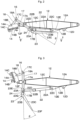
Fig. 2 is a left side view of an arm, a link, and a cylinder guard when a working tool cylinder is in a reduced state. -
Fig. 3 is a left side view of the arm, the link, and the cylinder guard when the working tool cylinder is between the reduced state and an extended state. -
Fig. 4 is a left side view of the arm, the link, and the cylinder guard when the working tool cylinder is in the extended state. -
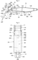
Fig. 5 is an elevation view of the arm, the link, the working tool cylinder, and the cylinder guard, viewed along arrows V-V inFig. 2 . -
Fig. 6 is a perspective view of the cylinder guard as a single unit. -
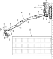
Fig. 7 is a left side view of a state where the hydraulic excavator performs demolition work of a building. -
Fig. 8 is a left side view of a working mechanism performing demolition work, with the working tool cylinder in the reduced state. -
Fig. 9 is a left side view of the working mechanism performing demolition work, with the working tool cylinder between the reduced state and the extended state. -
Fig. 10 is a left side view of the working mechanism performing demolition work, with the working tool cylinder in the extended state. - Hereinafter, an embodiment of a construction machine of the present invention will be described in detail with reference to the attached drawings by way of the cases applied to hydraulic excavators for demolition work as an example. In this embodiment, the running direction of a hydraulic excavator is defined as front-and-rear direction, and the direction perpendicular to the running direction is defined as right-and-left direction.
- A
hydraulic excavator 1 for demolition work is configured to include a self-propelled crawler typelower traveling structure 2, an upper revolvingstructure 3 mounted rotatably on thelower traveling structure 2, and aworking mechanism 8 provided on a front side of the upper revolvingstructure 3. Thelower traveling structure 2 and the upper revolvingstructure 3 constitute a vehicle body of thehydraulic excavator 1. Thehydraulic excavator 1 is suitably used for demolition work for structures having a large ground height such as high-rise buildings. - The upper revolving
structure 3 is configured to include a revolvingframe 4 that is to be a base, acounterweight 5 provided on a rear end side of the revolvingframe 4, acab 6 disposed on a front left side of the revolvingframe 4, and ahousing cover 7 disposed on a front side of thecounterweight 5. Thecab 6 defines an operator's room for an operator to steer thehydraulic excavator 1, thecab 6 being provided with a traveling lever and pedal device controlling the traveling operation of thelower traveling structure 2 and a control lever device controlling the revolving operation of theupper revolving structure 3 and the operation of the working mechanism 8 (each not shown). Onboard equipment (not shown), including an engine, a hydraulic pump, and a heat exchanger, is accommodated inside thehousing cover 7. - A support bracket (not shown) of mountain shape rising up from a bottom plate is integrally provided at a front end of the revolving
frame 4. The support bracket rotatably supports a base end side of a later-describedlower boom 9 and rotatably supports a base end side of aboom cylinder 19. - The multi-boom
type working mechanism 8 is mounted at a front end portion of the revolvingframe 4 that constitutes the upper revolvingstructure 3. Theworking mechanism 8 is configured to include alower boom 9 and anupper boom 10 that constitute a boom, amiddle arm 11 and anarm 12 that constitute an arm, aworking tool 13, and alink 16. - The base end side of the
lower boom 9 is mounted rotatably on the front end side of the revolving frame 4 (the support bracket). A base end side of theupper boom 10 is fixed on a tip end of thelower boom 9 with a fastener such as a bolt. A base end side of themiddle arm 11 is connected rotatably to a tip end of theupper boom 10 with apin 11A. Themiddle arm 11 is provided with afirst bracket 11B and asecond bracket 11C, which are adjacent to each other. A base end side of thearm 12 is connected rotatably to a tip end of themiddle arm 11 with apin 11D. - The
arm 12 is formed as an angular tubular body of cross-sectionally rectangular shape surrounded by anupper surface 12A, alower surface 12B, and right andleft side surfaces 12C. As shown inFig. 10 , thelower surface 12B of thearm 12 faces theupper boom 10 when thearm 12 is folded on theupper boom 10 side. Thelower surface 12B of thearm 12 is provided with afirst bracket 12D and asecond bracket 12E, which are adjacent to each other. Ajoint device 14 of theworking tool 13 is connected rotatably to a tip end of thearm 12 with apin 12F. - The
working tool 13 is mounted rotatably at the tip end of thearm 12. In this embodiment, theworking tool 13 is configured by thejoint device 14 and acrusher 15. - The
joint device 14 is a device for mounting a working attachment such as a bucket, a grapple, and thecrusher 15 replacing the tip end of thearm 12, depending on the type of operation of thehydraulic excavator 1. In this embodiment, thecrusher 15 for demolition work is mounted on thejoint device 14, both of which make up theworking tool 13. As shown inFig. 2 , thejoint device 14 includes abase member 14A, afixed hook 14B fixed on thebase member 14A, and amovable hook 14C. Themovable hook 14C is provided movably on thebase member 14A to move in a direction approaching or separating from the fixedhook 14B. - The
crusher 15 for demolition work is mounted rotatably at the tip end of thearm 12 through thejoint device 14. A base end side of thecrusher 15 is provided with twopins 15A, whose engagement with the fixedhook 14B and themovable hook 14C of thejoint device 14 allows thecrusher 15 to be fixed on thejoint device 14. Thecrusher 15 includes right and leftpaw members 15B that open and close with a hydraulic cylinder to crush a building and collect fragments at nearby stable places to prevent such crushed pieces from falling down. - The
link 16 is provided on the tip end side of thearm 12 to connect a later-describedworking tool cylinder 22 and the workingtool 13. As shown inFigs. 2 to 5 , thelink 16 is configured by afirst link 17 and asecond link 18, and rotates in synchronization with an expanding or contracting operation of the workingtool cylinder 22 to rotate the workingtool 13 relative to thearm 12. - The
first link 17 is formed of a pair of link plates linearly extending, which face each other in the right-and-left direction, with thearm 12 disposed therebetween. An intermediate portion in a length direction of thefirst link 17 is connected rotatably to a position adjacent to a connecting portion (pin 12F) with thejoint device 14 on the tip end side of thearm 12 through apin 17A. Oneend 17B in the length direction of thefirst link 17 is disposed on thelower surface 12B side of thearm 12 and connected to arod 22B of the workingtool cylinder 22. Theother end 17C in the length direction of thefirst link 17 is disposed on theupper surface 12A side of thearm 12 and connected to thesecond link 18. The right and leftfirst links 17 are each provided on oneend 17B side with two sheet screws (not shown). - The
second link 18 is provided between theother end 17C of thefirst link 17 and thejoint device 14 to connect these two elements. One end in a length direction of thesecond link 18 is connected rotatably to theother end 17C of thefirst link 17 through apin 18A. The other end in the length direction of thesecond link 18 is connected rotatably at a position separate from thepin 12F on thebase member 14A of thejoint device 14 with apin 18B. - A pair of (2) right and left
boom cylinders 19 are provided between the revolvingframe 4 and the lower boom 9 (only left side shown). A bottom side of theboom cylinder 19 is mounted rotatably on the support bracket of the revolvingframe 4. A rod side of theboom cylinder 19 is connected rotatably on the tip end side of thelower boom 9 with apin 19A. A pair of (2) right and leftmiddle arm cylinders 20 are provided between theupper boom 10 and the middle arm 11 (only left side shown). A bottom side of themiddle arm cylinder 20 is connected rotatably to theupper boom 10 with apin 20A, and a rod side of themiddle arm cylinder 20 is connected rotatably to thefirst bracket 11B of themiddle arm 11 with apin 20B. Anarm cylinder 21 is provided between themiddle arm 11 and thearm 12. A bottom side of thearm cylinder 21 is connected rotatably to thesecond bracket 11C of themiddle arm 11 with apin 21A, and a rod side of thearm cylinder 21 is connected rotatably to thefirst bracket 12D of thearm 12 with apin 21B. - The working
tool cylinder 22 is disposed on thelower surface 12B side of thearm 12 and provided between thearm 12 and thelink 16. The workingtool cylinder 22 includes atube 22A, a piston (not shown) provided slidably within thetube 22A, and therod 22B whose base end is mounted on the piston and whose tip end side projects from thetube 22A. One end (tube 22A) in a length direction of the workingtool cylinder 22 is connected rotatably to thesecond bracket 12E of thearm 12 with apin 22C. The other end (rod 22B) in the length direction of the workingtool cylinder 22 is connected rotatably to the oneend 17B of thefirst link 17 with apin 22D. - Therefore, the working
tool cylinder 22 performs an expanding or contracting operation to allow thefirst link 17 to rotate about a connecting portion (pin 17A) with thearm 12 and the resulting motion of thefirst link 17 is transmitted to thejoint device 14 through thesecond link 18. As a result, the workingtool 13 composed of thejoint device 14 and thecrusher 15 rotates about a connecting portion (pin 12F) with thearm 12. In this embodiment, the workingtool cylinder 22 expands or contracts between a reduced state and an extended state to allow thecrusher 15 to be rotationally displaced in the ranges shown inFig. 8 to Fig. 10 and perform demolition work of a building. - In this case, the working
tool cylinder 22 is disposed on thelower surface 12B side of thearm 12, which thus allows the workingtool cylinder 22 to be in an extension motion to rotate the workingtool 13 upward about thepin 12F. Meanwhile, the workingtool cylinder 22 is in a reduction motion to rotate the workingtool 13 downward. Therefore, as compared with cases where the workingtool cylinder 22 is disposed on theupper surface 12A side of thearm 12, the workingtool cylinder 22 is in the extension motion to successfully generate large forces to raise waste materials including reinforcing bars and concrete generated in demolition work using the workingtool 13. - Subsequently, a
cylinder guard 23 used in this embodiment will be described with reference toFig. 2 to Fig. 6 . Thecylinder guard 23 is fixed on the pair offirst links 17 that constitute thelink 16. Thecylinder guard 23 is interposed between the workingtool 13 and the workingtool cylinder 22 to protect the workingtool cylinder 22 when the workingtool cylinder 22 expands or contracts between the reduced state (the state shown inFig. 2 ) and the extended state (the state shown inFig. 4 ). - As shown in
Fig. 6 , thecylinder guard 23 is formed of a rectangular plate such as a steel plate. Thecylinder guard 23 includes a mountingplate portion 23A mounted on the pair offirst links 17 and aguard plate portion 23B provided integrally at the mountingplate portion 23A and inclined relative thereto. Theguard plate portion 23B has a set tilting angle to the mountingplate portion 23A such that the workingtool cylinder 22 is the closest to the workingtool cylinder 22 in the reduced state shown inFig. 2 . As shown inFig. 2 andFig. 5 , thecylinder guard 23 has a length dimension covering the workingtool cylinder 22 in the reduced state over the entire length. In addition, a width dimension of thecylinder guard 23 is set slightly larger than the interval of the pair offirst links 17, and either end side of thecylinder guard 23 in a width direction is provided with a bendingportion 23C. The bendingportion 23C is folded at right angles relative to the mountingplate portion 23A and theguard plate portion 23B to increase the entire strength of thecylinder guard 23. - The mounting
plate portion 23A of thecylinder guard 23 is provided with a plurality of (e.g., four) bolt throughholes 23D. The bolt throughholes 23D correspond to two sheet screws (not shown) provided for each of the pair offirst links 17 that constitute thelink 16. Therefore, abolt 24 inserted into each of the bolt throughholes 23D is screwed into a sheet screw of each of the pair offirst links 17 to fix thecylinder guard 23 on thefirst links 17. Accordingly, thecylinder guard 23 has oneend 23E in a length direction thereof, which is fixed on thefirst link 17, and theother end 23F in the length direction, which is a free end. The angle θ formed by theguard plate portion 23B of thecylinder guard 23 and thefirst link 17 is constant regardless of an expanding or contracting operation of the workingtool cylinder 22. - In addition, a semicircular notched
portion 23G is formed at each position on the axis of thepin 22D connecting the workingtool cylinder 22 and thefirst link 17, the position being at the bendingportion 23C provided on both end sides in a width direction of the mountingplate portion 23A. The notchedportion 23G prevents interference of both ends of thepin 22D with the bendingportion 23C when thecylinder guard 23 is mounted on thefirst link 17. - The
hydraulic excavator 1 of this embodiment is configured as described, and as shown inFig. 7 , for example, thehydraulic excavator 1 is self-propelled by thelower traveling structure 2 to approach abuilding 100 to be demolished. Then, theboom cylinder 19, themiddle arm cylinder 20, and thearm cylinder 21 of the workingmechanism 8 are each in the extended state, while thelower boom 9, theupper boom 10, themiddle arm 11, and thearm 12 are allowed to rise linearly. As a result, the workingtool 13 comes at a high place to allow thehydraulic excavator 1 to cause thecrusher 15 to demolish thebuilding 100 and to discard waste materials including reinforcing bars and concrete onto a loading platform of a transport vehicle (not shown). - Herein, when the working
mechanism 8 is allowed to rise linearly to perform demolition work, as shown inFig. 8 , the workingtool cylinder 22 is in the reduced state to rotate the workingtool 13 downward about thepin 12F and allow thecrusher 15 to demolish thebuilding 100. Accordingly, while the workingmechanism 8 is allowed to stand linearly, the working tool 13 (crusher 15) is normally rotated downward around thepin 12F to perform demolition work. It is not a common practice to rotate the workingtool 13 downward around thepin 12F to perform demolition work. In this state, the workingtool cylinder 22 is close to thebuilding 100. However, the workingtool cylinder 22 in the reduced state allows thecylinder guard 23 to cover the entireworking tool cylinder 22. Consequently, even if fragments including reinforcing bars and concrete are scattered around thecrusher 15 to demolish thebuilding 100 with thecrusher 15, thecylinder guard 23 can prevent such pieces from hitting the workingtool cylinder 22 to protect the workingtool cylinder 22. - As shown in
Fig. 9 , when thearm 12 is extended in a horizontal direction from the tip end of themiddle arm 11 to perform demolition work, the workingtool cylinder 22 is held between the reduced state and the extended state. Then, while the workingtool 13 is directly opposed to thebuilding 100, thecrusher 15 is allowed to demolish thebuilding 100. Accordingly, it is not a common practice to rotate the workingtool 13 downward around thepin 12F to perform demolition work, with thearm 12 extending in the horizontal direction. In this state, thecylinder guard 23 is directly opposed to thebuilding 100 to protect the workingtool cylinder 22 from fragments including reinforcing bars and concrete scattered from thebuilding 100. - In addition, as shown in
Fig. 10 , when thearm 12 is extended downward from the tip end of themiddle arm 11 to perform demolition work, the workingtool cylinder 22 stays away from thebuilding 100 and thearm 12 is disposed between thebuilding 100 and the workingtool cylinder 22. Also, a tip end side of therod 22B of the workingtool cylinder 22 projecting from the tip end of thearm 12 is covered with thecylinder guard 23. In this state, thearm 12 can protect most of thetube 22A and therod 22B of the workingtool cylinder 22 from fragments including reinforcing bars and concrete scattered from thebuilding 100. Meanwhile, the tip end side of therod 22B of the workingtool cylinder 22 can be protected by thecylinder guard 23. - Accordingly, the
cylinder guard 23 of this embodiment can constantly be interposed between the workingtool 13 and the workingtool cylinder 22 to protect the workingtool cylinder 22 while the workingtool cylinder 22 expands or contracts between the reduced state and the extended state. In this case, the oneend 23E side of thecylinder guard 23 is fixed on thefirst link 17 of thelink 16 with thebolt 24, and thecylinder guard 23 is rotationally displaced integrally with thefirst link 17 to protect the workingtool cylinder 22. Thus, thecylinder guard 23 causes no drawback of motion defect due to biting of fragments into a sliding portion, as opposed to a cylinder guard of conventional art in which 2 members of a rod-side guard and a tube-side guard are assembled slidably and displaceably. Therefore, thecylinder guard 23 can assuredly protect the workingtool cylinder 22 over extended periods of time. - Moreover, the
cylinder guard 23, which is formed of a single part, can readily be mounted on thefirst link 17 with thebolt 24. Therefore, thecylinder guard 23 is characterized by reduced numbers of parts and mounting operations, as opposed to a cylinder guard of conventional art composed of 2 members of a rod-side guard and a tube-side guard. Therefore, thecylinder guard 23 can contribute to reducing manufacturing costs. - Therefore, in the
hydraulic excavator 1 of this embodiment, the workingmechanism 8 includes thelower boom 9 and theupper boom 10 mounted rotatably on the upper revolvingstructure 3, themiddle arm 11 and thearm 12 mounted rotatably at the tip end of theupper boom 10, the workingtool 13 mounted rotatably at the tip end of thearm 12, the workingtool cylinder 22 whose one end is mounted on thearm 12 to rotate the workingtool 13, and thelink 16 mounted rotatably on the tip end side of thearm 12 and connecting the other end of the workingtool cylinder 22 and the workingtool 13, in which the workingtool cylinder 22 is disposed on thelower surface 12B side of thearm 12 that faces theupper boom 10 when thearm 12 is folded on theupper boom 10 side, and thelink 16 is provided with thecylinder guard 23 that is rotationally displaced in synchronization with an expanding or contracting operation of the workingtool cylinder 22 and is interposed between the workingtool 13 and the workingtool cylinder 22. - According to this configuration, the
cylinder guard 23 is rotationally displaced in synchronization with the expanding or contracting operation of the workingtool cylinder 22 to move together with thelink 16, and is interposed between the workingtool 13 and the workingtool cylinder 22. Consequently, thecylinder guard 23 can prevent fragments scattered from a building from hitting the workingtool cylinder 22 to protect the workingtool cylinder 22 when the building is demolished using the workingtool 13. - In the embodiment, the
cylinder guard 23 has a length dimension covering the workingtool cylinder 22 in the reduced state over the entire length, formed of a plate provided with the bendingportion 23C at both ends in a width direction, and fixed to thefirst link 17 at a constant angle. This configuration allows no sliding portion to be provided between thecylinder guard 23 and thefirst link 17. Therefore, no biting of fragments generated by demolition work into the sliding portion occurs to avoid motion defect of thecylinder guard 23. Also, the bendingportion 23C can increase the entire strength of thecylinder guard 23. - In the embodiment, the
cylinder guard 23 has the oneend 23E side in a length direction thereof, which is fixed on thefirst link 17, and theother end 23F in the length direction, which is a free end. This configuration allows thecylinder guard 23 to be rotationally displaced together with thefirst link 17, depending on an expanding or contracting operation of the workingtool cylinder 22, to protect the workingtool cylinder 22. - In fact, the embodiment exemplifies a case where a
crusher 15 is mounted at a tip end of anarm 12 through ajoint device 14. However, the present invention is not restricted to that, and thecrusher 15 may directly be mounted at the tip end of thearm 12. - Also, the embodiment exemplifies a case where an
arm 12 is mounted at a tip end of anupper boom 10 through amiddle arm 11. However, the present invention is not restricted to that, and thearm 12 may directly be mounted at the tip end of theupper boom 10. - Moreover, the embodiment exemplifies a case where a
crusher 15 for demolition work is mounted at a tip end of anarm 12 through ajoint device 14. However, the present invention is not limited to that, and may be widely employed in hydraulic excavators including working tools such as a bucket, a grapple, and a lifting magnet. -
- 1: Hydraulic excavator (Construction machine)
- 2: Lower traveling structure (Vehicle body)
- 3: Upper revolving structure (Vehicle body)
- 8: Working mechanism
- 9: Lower boom (boom)
- 10: Upper boom (boom)
- 11: Middle arm (arm)
- 12: Arm
- 12B: Lower surface
- 13: Working tool
- 16: Link
- 17: First link
- 18: Second link
- 22: Working tool cylinder
- 23: Cylinder guard
- 23C: Bending portion
- 23E: One end
- 23F: The other end
Claims (3)
- A construction machine comprising a self-propelled vehicle body and a working mechanism provided on the vehicle body,
the working mechanism comprising:a boom mounted rotatably on the vehicle body;an arm mounted rotatably at a tip end of the boom;a working tool mounted rotatably at a tip end of the arm;a working tool cylinder whose one end is mounted on the arm to rotate the working tool; anda link mounted rotatably on the tip end side of the arm and connecting the other end of the working tool cylinder and the working tool, whereinthe working tool cylinder is disposed on a lower surface side of the arm that faces the boom when the arm is folded on the boom side, andthe link is provided with a cylinder guard that is rotationally displaced in synchronization with an expanding or contracting operation of the working tool cylinder and is interposed between the working tool and the working tool cylinder. - The construction machine according to claim 1, wherein
the cylinder guard has a length dimension covering the working tool cylinder in a reduced state over the entire length, is formed of a plate provided with a bending portion at both ends in a width direction, and is fixed to the link at a constant angle. - The construction machine according to claim 1 or 2, wherein
the cylinder guard has one end in a length direction thereof, which is fixed on the link, and the other end in the length direction, which is a free end.
Applications Claiming Priority (2)
| Application Number | Priority Date | Filing Date | Title |
|---|---|---|---|
| JP2021061496 | 2021-03-31 | ||
| PCT/JP2022/005331 WO2022209339A1 (en) | 2021-03-31 | 2022-02-10 | Construction machine |
Publications (2)
| Publication Number | Publication Date |
|---|---|
| EP4187019A1 true EP4187019A1 (en) | 2023-05-31 |
| EP4187019A4 EP4187019A4 (en) | 2024-10-09 |
Family
ID=83455908
Family Applications (1)
| Application Number | Title | Priority Date | Filing Date |
|---|---|---|---|
| EP22779568.9A Pending EP4187019A4 (en) | 2021-03-31 | 2022-02-10 | CONSTRUCTION MACHINE |
Country Status (6)
| Country | Link |
|---|---|
| US (1) | US12534869B2 (en) |
| EP (1) | EP4187019A4 (en) |
| JP (1) | JP7339469B2 (en) |
| KR (1) | KR102792501B1 (en) |
| CN (1) | CN116113739B (en) |
| WO (1) | WO2022209339A1 (en) |
Families Citing this family (1)
| Publication number | Priority date | Publication date | Assignee | Title |
|---|---|---|---|---|
| JP7689504B2 (en) * | 2022-03-24 | 2025-06-06 | 日立建機株式会社 | Work Machine |
Family Cites Families (19)
| Publication number | Priority date | Publication date | Assignee | Title |
|---|---|---|---|---|
| JPS5750450Y2 (en) * | 1978-06-09 | 1982-11-04 | ||
| JPS5847345A (en) | 1981-09-16 | 1983-03-19 | Nippon Telegr & Teleph Corp <Ntt> | Intermittent receiving system and intermittent receiving mobile station device |
| JPH04133518U (en) | 1991-05-29 | 1992-12-11 | オカダアイヨン株式会社 | Rod protector for crushing cutting machine |
| JPH0512708U (en) * | 1991-08-01 | 1993-02-19 | 油谷重工株式会社 | Cylinder guard device for construction machinery |
| US5386652A (en) * | 1993-11-12 | 1995-02-07 | Allied Gator, Inc. | Cylinder guard |
| JP3000513U (en) * | 1994-01-28 | 1994-08-09 | 古河機械金属株式会社 | Piston rod protection device for hydraulic cylinder for crusher |
| JPH08296611A (en) * | 1995-04-26 | 1996-11-12 | Kobelco Kenki Eng Kk | Hydraulic cylinder protector |
| JP3718434B2 (en) * | 2001-01-23 | 2005-11-24 | 株式会社クボタ | Cylinder protection device |
| JP3894881B2 (en) * | 2002-12-06 | 2007-03-22 | ヤンマー株式会社 | Mobile crusher |
| JP3868370B2 (en) * | 2002-12-11 | 2007-01-17 | ヤンマー株式会社 | Mobile work vehicle |
| JP4038197B2 (en) * | 2004-07-01 | 2008-01-23 | ヤンマー株式会社 | Cylinder protection device |
| JP5322557B2 (en) * | 2008-09-22 | 2013-10-23 | 日立建機株式会社 | Construction machine arm |
| KR101068208B1 (en) * | 2009-11-30 | 2011-09-28 | 대모 엔지니어링 주식회사 | Piston Rod Protective Cover on Arm Cylinder for Material Handler Operation |
| JP2013104275A (en) * | 2011-11-16 | 2013-05-30 | Sumitomo (Shi) Construction Machinery Co Ltd | High altitude demolition machine |
| JP2014015780A (en) | 2012-07-10 | 2014-01-30 | Hitachi Constr Mach Co Ltd | Guard device of hydraulic cylinder |
| CN103541400B (en) * | 2013-10-18 | 2016-04-27 | 徐州徐工特种工程机械有限公司 | A kind of loader-digger support oil cylinder protection mechanism |
| KR20160006349A (en) * | 2014-07-08 | 2016-01-19 | 현대중공업 주식회사 | Apparatus for Cylinder Protection of Construction Equipment |
| JP6509693B2 (en) * | 2015-09-11 | 2019-05-08 | 株式会社日立建機ティエラ | Cylinder device |
| CN108487364B (en) * | 2018-03-13 | 2020-07-21 | 柳州柳工挖掘机有限公司 | Excavator bucket cylinder protection mechanism |
-
2022
- 2022-02-10 CN CN202280006325.3A patent/CN116113739B/en active Active
- 2022-02-10 WO PCT/JP2022/005331 patent/WO2022209339A1/en not_active Ceased
- 2022-02-10 US US18/025,458 patent/US12534869B2/en active Active
- 2022-02-10 KR KR1020237008132A patent/KR102792501B1/en active Active
- 2022-02-10 JP JP2023510599A patent/JP7339469B2/en active Active
- 2022-02-10 EP EP22779568.9A patent/EP4187019A4/en active Pending
Also Published As
| Publication number | Publication date |
|---|---|
| CN116113739A (en) | 2023-05-12 |
| JP7339469B2 (en) | 2023-09-05 |
| US12534869B2 (en) | 2026-01-27 |
| JPWO2022209339A1 (en) | 2022-10-06 |
| EP4187019A4 (en) | 2024-10-09 |
| KR102792501B1 (en) | 2025-04-08 |
| KR20230047176A (en) | 2023-04-06 |
| US20230332372A1 (en) | 2023-10-19 |
| WO2022209339A1 (en) | 2022-10-06 |
| CN116113739B (en) | 2026-07-07 |
Similar Documents
| Publication | Publication Date | Title |
|---|---|---|
| US5183216A (en) | Demolishing apparatus | |
| EP0596285B1 (en) | Reinforced steel shear | |
| EP1903152A2 (en) | Upper frame structure for supporting cab of construction machinery | |
| US20130048400A1 (en) | Machine access device | |
| LT3788B (en) | Excavator | |
| US7832127B2 (en) | Apparatus for attaching a work tool to a loader | |
| US12534869B2 (en) | Construction machine | |
| JP7574106B2 (en) | Construction Machinery | |
| US20060108462A1 (en) | Cutting or crushing implement | |
| NZ237318A (en) | Ripper frame having pitch control, integral frame and push block | |
| CN118745904A (en) | Shearing device and lane repair vehicle | |
| JP7715663B2 (en) | Construction machinery | |
| US4601626A (en) | Arrangement for swinging an attachment holder for the equipment of a hydraulic excavator | |
| JP2014015780A (en) | Guard device of hydraulic cylinder | |
| JP5265463B2 (en) | Construction machinery | |
| EP0638691B1 (en) | Heavy duty shear | |
| CN1065605A (en) | Concrete deck pulverizer | |
| RU2283467C1 (en) | Engine track vehicle on base tank chassis | |
| EP2423393A1 (en) | Cab protection structure for construction machinery | |
| JP7689504B2 (en) | Work Machine | |
| KR102964488B1 (en) | Cylinder guard and construction machine having the same | |
| JP4408428B2 (en) | Work tool angle detection device for work machines | |
| EP4379144A1 (en) | Work vehicle | |
| KR102775876B1 (en) | Bolt tightening robot for high space | |
| JP3602770B2 (en) | Offset boom type construction machine |
Legal Events
| Date | Code | Title | Description |
|---|---|---|---|
| STAA | Information on the status of an ep patent application or granted ep patent |
Free format text: STATUS: THE INTERNATIONAL PUBLICATION HAS BEEN MADE |
|
| PUAI | Public reference made under article 153(3) epc to a published international application that has entered the european phase |
Free format text: ORIGINAL CODE: 0009012 |
|
| STAA | Information on the status of an ep patent application or granted ep patent |
Free format text: STATUS: REQUEST FOR EXAMINATION WAS MADE |
|
| 17P | Request for examination filed |
Effective date: 20230223 |
|
| AK | Designated contracting states |
Kind code of ref document: A1 Designated state(s): AL AT BE BG CH CY CZ DE DK EE ES FI FR GB GR HR HU IE IS IT LI LT LU LV MC MK MT NL NO PL PT RO RS SE SI SK SM TR |
|
| DAV | Request for validation of the european patent (deleted) | ||
| DAX | Request for extension of the european patent (deleted) | ||
| A4 | Supplementary search report drawn up and despatched |
Effective date: 20240910 |
|
| RIC1 | Information provided on ipc code assigned before grant |
Ipc: E02F 9/00 20060101ALI20240904BHEP Ipc: E02F 3/36 20060101AFI20240904BHEP |