EP4187009B1 - Haushaltsgerät mit einem knopf - Google Patents
Haushaltsgerät mit einem knopf Download PDFInfo
- Publication number
- EP4187009B1 EP4187009B1 EP22199048.4A EP22199048A EP4187009B1 EP 4187009 B1 EP4187009 B1 EP 4187009B1 EP 22199048 A EP22199048 A EP 22199048A EP 4187009 B1 EP4187009 B1 EP 4187009B1
- Authority
- EP
- European Patent Office
- Prior art keywords
- fixing
- household appliance
- fixing member
- claw
- circumferential wall
- Prior art date
- Legal status (The legal status is an assumption and is not a legal conclusion. Google has not performed a legal analysis and makes no representation as to the accuracy of the status listed.)
- Active
Links
Images


Classifications
-
- D—TEXTILES; PAPER
- D06—TREATMENT OF TEXTILES OR THE LIKE; LAUNDERING; FLEXIBLE MATERIALS NOT OTHERWISE PROVIDED FOR
- D06F—LAUNDERING, DRYING, IRONING, PRESSING OR FOLDING TEXTILE ARTICLES
- D06F34/00—Details of control systems for washing machines, washer-dryers or laundry dryers
- D06F34/28—Arrangements for program selection, e.g. control panels therefor; Arrangements for indicating program parameters, e.g. the selected program or its progress
- D06F34/30—Arrangements for program selection, e.g. control panels therefor; Arrangements for indicating program parameters, e.g. the selected program or its progress characterised by mechanical features, e.g. buttons or rotary dials
-
- A—HUMAN NECESSITIES
- A47—FURNITURE; DOMESTIC ARTICLES OR APPLIANCES; COFFEE MILLS; SPICE MILLS; SUCTION CLEANERS IN GENERAL
- A47L—DOMESTIC WASHING OR CLEANING; SUCTION CLEANERS IN GENERAL
- A47L15/00—Washing or rinsing machines for crockery or tableware
- A47L15/42—Details
- A47L15/4293—Arrangements for programme selection, e.g. control panels; Indication of the selected programme, programme progress or other parameters of the programme, e.g. by using display panels
-
- G—PHYSICS
- G05—CONTROLLING; REGULATING
- G05G—CONTROL DEVICES OR SYSTEMS INSOFAR AS CHARACTERISED BY MECHANICAL FEATURES ONLY
- G05G1/00—Controlling members, e.g. knobs or handles; Assemblies or arrangements thereof; Indicating position of controlling members
- G05G1/08—Controlling members for hand actuation by rotary movement, e.g. hand wheels
Definitions
- the present invention relates to a household appliance comprising a rotary knob which is mounted to the control panel.
- Household appliances such as laundry washing/drying machines, cooking appliances, dishwashers, etc. usually comprise a control panel whereon rotary knobs which enable the operational status to be determined as per the preference of the users are disposed.
- the knobs are attached to a shaft connected to the control card disposed behind the control panel by means of the housings on the control panel. When the user rotates the knob, the movement is transferred to the shaft such that the user preference is transmitted to the control card.
- the knobs which are directly related to the use of the household appliance, are one of the most used components on the household appliance by the user, and are generally configured as multi-part components in line with various cosmetic needs and structural designs to increase the quality perception of the users.
- One embodiment preferred by the manufacturers to increase the quality perception of the knobs is to increase the weight of the knob by placing various weight pieces inside the knob to provide a strong feel.
- a washing machine comprising a control panel having a rotatable switch which comprises a contour part, a switch part and a glossing part contains metallic materials is disclosed.
- the aim of the present invention is the realization of a household appliance comprising a knob with decreased operating defects and improved quality perception.
- the household appliance realized in order to attain the aim of the present invention, explicated in the first claim and the respective claims thereof.
- the intermediate member and the handle are directly fixed onto the metal fixing member. While centering the intermediate member and the handle relative to each other, the fixing member also provides the elimination of stretching and increases the weight of the knob by acting as a weight.
- the metal fixing member which supports and centers the handle and the intermediate member, production and assembly tolerances are decreased and the weight of the knob is increased without the need for a separate weight piece mounting.
- the handle is composed of a plurality of components and each component is fixed to the fixing member.
- the handle is configured in at least two components, a circumferential wall defining the lateral circumferential surface thereof and a cover defining the front face thereof, and the circumferential wall and the cover are fixed onto the intermediate member without being directly fixed to each other so as to be seated on top of each other.
- the cover is configured as a multi-part component so as to have a frame and a plate, and the frame and the plate are fixed to the fixing member.
- the household appliance comprises the intermediate member having a support portion extending out of the housing, and the fixing member having a body which is fitted over the support portion and remains between the support portion and the circumferential wall so as to be fixed on the support portion and the circumferential wall.
- the body is a hollow cylinder and is fitted over the support portion while the circumferential wall is fixed to the body.
- first claw on the outside of the support facing the circumferential wall and at least one second claw on the inside of the body facing the circumferential wall while the circumferential wall has at least one first claw housing wherein the first claw is fitted, and at least one second claw housing wherein the second claw is fitted.
- the first claw and the second claw which are provided on the handle and the intermediate member and which are manufactured from a more flexible material relative to the fixing member, for example plastic material, stretch during the assembly so as to be fitted into the housings on the circumferential wall.
- a skirt extending almost perpendicular to the body is provided on the fixing member and the cover is fixed onto the skirt.
- the frame and the plate are fixed on the fixing member without being fixed to each other.
- the skirt provides support to the cover, which is manufactured from a material with less resistance.
- each of the intermediate member, body, frame and front plate is fixed on and supported by the fixing member. Consequently, possible misalignments and eccentricities of each component relative to each other are tolerated.
- the fixing member is manufactured from zamak.
- the fixing member is enabled to be low cost and have high strength, and in case the household appliance is placed in a high humidity environment such as a bathroom or used with wet hands, the liquid reaching the fixing member through the mounting gaps is prevented from causing wear and corrosion over time.
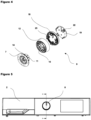
- the household appliance (1) comprises a panel (2) which is configured to enable the user to control the functions of the household appliance (1); a control unit (3) which is disposed behind the panel (2); a shaft (4) which transmits the preferences of the user to the control unit (3) and which is connected to the control unit (3); a housing (5) which is arranged on the panel (2); a bearing (6) which is configured to bear the shaft (4); and a knob (9) having an intermediate member (7) which is fitted into the housing (5) so as to bear against the panel (2) from behind the panel, and a handle (8) which is configured to enable the user to move the shaft (4).
- the household appliance (1) of the present invention comprises the knob (9) having a metal fixing member (10) whereon the intermediate member (7) and the handle (8) are fixed.
- the fixing member (10) is manufactured from metal while the intermediate member (7) and the handle (8) can be manufactured from various materials, such as plastic, which are low cost or which are preferred due to the outer appearance.
- the fixing member (10) provides high rigidity and significantly increases the weight of the knob (9).
- the household appliance (1) comprises the handle (8) composed of at least two components, each fixed onto the fixing member (10), one being a circumferential wall (12) and the other being a cover (20) positioned in front of the circumferential wall (12).
- the household appliance (1) comprises a support portion (11) which is arranged on the intermediate member (7) and which extends outwards from the housing (5), and the fixing member (10) having a body (13) which at least partially remains between the support portion (11) and the circumferential wall (12) and whereon the support portion (11) and the circumferential wall (12) are fixed.
- the household appliance (1) comprises at least one first fixing claw (14) which is provided on the support portion (11), at least one second fixing claw (15) which is provided on the circumferential wall (12), and the body (13) having at least one first fixing housing (16) wherein the first fixing claw (14) is fitted and at least one second fixing housing (17) wherein the second fixing claw (15) is fitted.
- the household appliance (1) comprises at least one skirt (21) which is provided on the fixing member (10), which extends almost perpendicular to the body (13) and whereon the cover (20) is fixed.
- the household appliance (1) comprises the cover (20) having a frame (18) which is fixed onto the fixing member (10) and which surrounds the side of the circumferential wall (12) and a plate (19) which is fitted into the frame (18) fixed onto the fixing member (10).
- the household appliance (1) comprises at least one third claw (22) which is provided on the plate (19), at least one fourth claw (23) which is provided on the frame (18), and at least one third fixing housing (24) and at least one fourth fixing member (25) which are provided on the skirt (21) and which receives the third fixing claw (22) and the fourth fixing claw (23), respectively.
- the household appliance (1) comprises the fixing member (10) manufactured from zamak.
- the handle (8) has a cover (20) which is disposed on the front surface of the body (13) and the cover (20) is fixed to the fixing member (10).
- the cover (20) is only seated onto the body (13) and fixed onto the fixing member (10) without being directly fixed onto the body (13).
- the body (13) and the cover (20) are centered by means of the fixing member (10), and the gaps and eccentricities between the cover (20) and the body (13) caused by the assembly and production tolerances are prevented from causing the knob (9) to malfunction.
- a household appliance (1) comprising a multi-part knob (9) with increased quality perception and improved ease of assembly.
Landscapes
- Engineering & Computer Science (AREA)
- Textile Engineering (AREA)
- Mechanical Control Devices (AREA)
Claims (8)
- Ein Haushaltsgerät (1) umfasst ein Paneel (2), das so gestaltet ist, dass es dem Benutzer ermöglicht, die Funktionen des Haushaltsgeräts (1) zu steuern; eine Steuereinheit (3), die hinter dem Paneel (2) angeordnet ist; eine Welle (4), die die Präferenzen des Benutzers an die Steuereinheit (3) überträgt und die mit der Steuereinheit (3) verbunden ist; ein Gehäuse (5), das auf dem Paneel (2) angeordnet ist; ein Lager (6), das so konfiguriert ist, dass es die Welle (4) trägt; und einen Knopf (9) mit einem Zwischenelement (7), das in das Gehäuse (5) eingepasst ist, so dass es von der Rückseite der Platte (2) an der Platte (2) anliegt, und einem Griff (8), der so konfiguriert ist, dass er es dem Benutzer ermöglicht, die Welle (4) zu bewegen, gekennzeichnet ist es dadurch, dass der Knopf (9) ein metallisches Befestigungselement (10) aufweist, an dem das Zwischenelement (7) und der Griff (8) befestigt sind.
- Ein Haushaltsgerät (1) wie in Anspruch 1 aufgeführt, ist dadurch gekennzeichnet, dass der Griff (8) aus mindestens zwei Komponenten besteht, von denen jede an dem Befestigungselement (10) befestigt ist, wobei eine Umfangswand (12) und die andere eine vor der Umfangswand (12) positionierte Abdeckung (20) ist.
- Ein Haushaltsgerät (1) wie in Anspruch 1 aufgeführt, ist dadurch gekennzeichnet, dass ein Stützabschnitt (11), der an dem Zwischenelement (7) angeordnet ist und der sich von dem Gehäuse (5) nach außen erstreckt, und das Befestigungselement (10) einen Körper (13) aufweisen, der zumindest teilweise zwischen dem Stützabschnitt (11) und der Umfangswand (12) verbleibt und an dem der Stützabschnitt (11) und die Umfangswand (12) befestigt sind.
- Ein Haushaltsgerät (1) wie in Anspruch 3 aufgeführt, ist dadurch gekennzeichnet, dass mindestens eine erste Befestigungsklaue (14), die an dem Trägerteil (11) vorgesehen ist, mindestens eine zweite Befestigungsklaue (15), die an der Umfangswand (12) vorgesehen ist, und der Körper (13) mindestens ein erstes Befestigungsgehäuse (16), in dem die erste Befestigungsklaue (14) angebracht ist, und mindestens ein zweites Befestigungsgehäuse (17), in dem die zweite Befestigungsklaue (15) angebracht ist, aufweist.
- Ein Haushaltsgerät (1) wie in einem der Ansprüche 2 bis 4 aufgeführt, ist dadurch gekennzeichnet, dass mindestens eine Schürze (21) am Befestigungselement (10) vorgesehen ist, die sich nahezu senkrecht zum Körper (13) erstreckt und an der die Abdeckung (20) befestigt ist.
- Ein Haushaltsgerät (1) wie in Anspruch 5 aufgeführt, ist dadurch gekennzeichnet, dass die Abdeckung (20) einen Rahmen (18), der an dem Befestigungselement (10) befestigt ist und die Seite der Umfangswand (12) umgibt, und eine Platte (19) aufweist, die in den an dem Befestigungselement (10) befestigten Rahmen (18) eingepasst ist.
- Ein Haushaltsgerät (1) wie in Anspruch 6 aufgeführt, ist dadurch gekennzeichnet, dass mindestens eine dritte Klaue (22), die auf der Platte (19) vorgesehen ist, mindestens eine vierte Klaue (23), die auf dem Rahmen (18) vorgesehen ist, und mindestens ein drittes Befestigungsgehäuse (24) und mindestens ein viertes Befestigungselement (25), die auf der Schürze (21) vorgesehen sind und die dritte Befestigungsklaue (22) bzw. die vierte Befestigungsklaue (23) aufnehmen.
- Ein Haushaltsgerät (1) wie in einem der vorherigen Ansprüche aufgeführt, ist dadurch gekennzeichnet, dass das Befestigungselement (10) aus Zamak hergestellt ist.
Applications Claiming Priority (1)
| Application Number | Priority Date | Filing Date | Title |
|---|---|---|---|
| TR202118854 | 2021-11-30 |
Publications (2)
| Publication Number | Publication Date |
|---|---|
| EP4187009A1 EP4187009A1 (de) | 2023-05-31 |
| EP4187009B1 true EP4187009B1 (de) | 2025-01-01 |
Family
ID=83546744
Family Applications (1)
| Application Number | Title | Priority Date | Filing Date |
|---|---|---|---|
| EP22199048.4A Active EP4187009B1 (de) | 2021-11-30 | 2022-09-30 | Haushaltsgerät mit einem knopf |
Country Status (2)
| Country | Link |
|---|---|
| EP (1) | EP4187009B1 (de) |
| PL (1) | PL4187009T3 (de) |
Families Citing this family (1)
| Publication number | Priority date | Publication date | Assignee | Title |
|---|---|---|---|---|
| US12554344B1 (en) | 2024-09-30 | 2026-02-17 | Whirlpool Corporation | Snap-in knob for an appliance console |
Family Cites Families (3)
| Publication number | Priority date | Publication date | Assignee | Title |
|---|---|---|---|---|
| WO2007043819A1 (en) * | 2005-10-12 | 2007-04-19 | Lg Electronics Inc. | Control unit of laundry processing apparatus |
| KR20100052211A (ko) * | 2008-11-10 | 2010-05-19 | 엘지전자 주식회사 | 세탁물 처리기기 |
| WO2018054801A1 (en) | 2016-09-20 | 2018-03-29 | Arcelik Anonim Sirketi | A household appliance comprising a knob |
-
2022
- 2022-09-30 PL PL22199048.4T patent/PL4187009T3/pl unknown
- 2022-09-30 EP EP22199048.4A patent/EP4187009B1/de active Active
Also Published As
| Publication number | Publication date |
|---|---|
| EP4187009A1 (de) | 2023-05-31 |
| PL4187009T3 (pl) | 2025-04-28 |
Similar Documents
| Publication | Publication Date | Title |
|---|---|---|
| EP2602377B1 (de) | Waschmaschine mit einer Knopfanordnung | |
| EP2140058B1 (de) | Wäschebehandlungsvorrichtung | |
| EP3189179B1 (de) | Waschmaschine | |
| CN209215975U (zh) | 包括旋钮装置的电器设备 | |
| EP4187009B1 (de) | Haushaltsgerät mit einem knopf | |
| US20110088733A1 (en) | Water-bearing domestic appliance | |
| US9297109B2 (en) | Laundry dryer | |
| US8438878B2 (en) | Control unit of laundry processing apparatus | |
| EP3516103B1 (de) | Haushaltsgerät mit einem knopf | |
| KR20160084073A (ko) | 의류처리장치 및 도어 | |
| EP2039821B1 (de) | Knopf-Aufbau für Waschmaschine und Herstellungsverfahren dafür | |
| GB2130438A (en) | Rotary knob | |
| CA2527758C (en) | Appliance with membrane overlay | |
| KR102375813B1 (ko) | 세탁기 | |
| JP2013085625A (ja) | ドラム式洗濯機 | |
| WO2013098243A2 (en) | A household appliance | |
| EP2764524B1 (de) | Haushaltsgerät | |
| EP3447182B1 (de) | Haushaltsgerät und verfahren zum betrieb eines haushaltsgeräts | |
| CN113611559B (zh) | 旋钮操作组件和家用电器 | |
| TR2021018854A2 (tr) | Bi̇r düğme i̇çeren bi̇r ev ci̇hazi | |
| WO2017044059A1 (en) | A household appliance comprising a decorative element that can be attached to/detached from the knob | |
| WO2020126468A1 (en) | A household appliance comprising a decorative element which can be attached to/detached from the knob | |
| EP4202104A1 (de) | Waschmaschine | |
| JP2023127882A (ja) | 洗濯機 | |
| KR101706969B1 (ko) | 의류처리장치 및 도어 |
Legal Events
| Date | Code | Title | Description |
|---|---|---|---|
| PUAI | Public reference made under article 153(3) epc to a published international application that has entered the european phase |
Free format text: ORIGINAL CODE: 0009012 |
|
| STAA | Information on the status of an ep patent application or granted ep patent |
Free format text: STATUS: REQUEST FOR EXAMINATION WAS MADE |
|
| 17P | Request for examination filed |
Effective date: 20220930 |
|
| AK | Designated contracting states |
Kind code of ref document: A1 Designated state(s): AL AT BE BG CH CY CZ DE DK EE ES FI FR GB GR HR HU IE IS IT LI LT LU LV MC MK MT NL NO PL PT RO RS SE SI SK SM TR |
|
| GRAP | Despatch of communication of intention to grant a patent |
Free format text: ORIGINAL CODE: EPIDOSNIGR1 |
|
| STAA | Information on the status of an ep patent application or granted ep patent |
Free format text: STATUS: GRANT OF PATENT IS INTENDED |
|
| RIC1 | Information provided on ipc code assigned before grant |
Ipc: G05G 1/08 20060101ALN20240802BHEP Ipc: A47L 15/42 20060101ALN20240802BHEP Ipc: D06F 34/30 20200101AFI20240802BHEP |
|
| INTG | Intention to grant announced |
Effective date: 20240826 |
|
| GRAS | Grant fee paid |
Free format text: ORIGINAL CODE: EPIDOSNIGR3 |
|
| GRAA | (expected) grant |
Free format text: ORIGINAL CODE: 0009210 |
|
| STAA | Information on the status of an ep patent application or granted ep patent |
Free format text: STATUS: THE PATENT HAS BEEN GRANTED |
|
| AK | Designated contracting states |
Kind code of ref document: B1 Designated state(s): AL AT BE BG CH CY CZ DE DK EE ES FI FR GB GR HR HU IE IS IT LI LT LU LV MC MK MT NL NO PL PT RO RS SE SI SK SM TR |
|
| REG | Reference to a national code |
Ref country code: GB Ref legal event code: FG4D |
|
| REG | Reference to a national code |
Ref country code: DE Ref legal event code: R096 Ref document number: 602022009286 Country of ref document: DE |
|
| REG | Reference to a national code |
Ref country code: CH Ref legal event code: EP |
|
| REG | Reference to a national code |
Ref country code: IE Ref legal event code: FG4D |
|
| REG | Reference to a national code |
Ref country code: LT Ref legal event code: MG9D |
|
| REG | Reference to a national code |
Ref country code: NL Ref legal event code: MP Effective date: 20250101 |
|
| REG | Reference to a national code |
Ref country code: AT Ref legal event code: MK05 Ref document number: 1756334 Country of ref document: AT Kind code of ref document: T Effective date: 20250101 |
|
| PG25 | Lapsed in a contracting state [announced via postgrant information from national office to epo] |
Ref country code: NL Free format text: LAPSE BECAUSE OF FAILURE TO SUBMIT A TRANSLATION OF THE DESCRIPTION OR TO PAY THE FEE WITHIN THE PRESCRIBED TIME-LIMIT Effective date: 20250101 |
|
| PG25 | Lapsed in a contracting state [announced via postgrant information from national office to epo] |
Ref country code: FI Free format text: LAPSE BECAUSE OF FAILURE TO SUBMIT A TRANSLATION OF THE DESCRIPTION OR TO PAY THE FEE WITHIN THE PRESCRIBED TIME-LIMIT Effective date: 20250101 |
|
| PG25 | Lapsed in a contracting state [announced via postgrant information from national office to epo] |
Ref country code: ES Free format text: LAPSE BECAUSE OF FAILURE TO SUBMIT A TRANSLATION OF THE DESCRIPTION OR TO PAY THE FEE WITHIN THE PRESCRIBED TIME-LIMIT Effective date: 20250101 |
|
| PG25 | Lapsed in a contracting state [announced via postgrant information from national office to epo] |
Ref country code: IS Free format text: LAPSE BECAUSE OF FAILURE TO SUBMIT A TRANSLATION OF THE DESCRIPTION OR TO PAY THE FEE WITHIN THE PRESCRIBED TIME-LIMIT Effective date: 20250501 Ref country code: NO Free format text: LAPSE BECAUSE OF FAILURE TO SUBMIT A TRANSLATION OF THE DESCRIPTION OR TO PAY THE FEE WITHIN THE PRESCRIBED TIME-LIMIT Effective date: 20250401 |
|
| PG25 | Lapsed in a contracting state [announced via postgrant information from national office to epo] |
Ref country code: HR Free format text: LAPSE BECAUSE OF FAILURE TO SUBMIT A TRANSLATION OF THE DESCRIPTION OR TO PAY THE FEE WITHIN THE PRESCRIBED TIME-LIMIT Effective date: 20250101 |
|
| PG25 | Lapsed in a contracting state [announced via postgrant information from national office to epo] |
Ref country code: LV Free format text: LAPSE BECAUSE OF FAILURE TO SUBMIT A TRANSLATION OF THE DESCRIPTION OR TO PAY THE FEE WITHIN THE PRESCRIBED TIME-LIMIT Effective date: 20250101 Ref country code: PT Free format text: LAPSE BECAUSE OF FAILURE TO SUBMIT A TRANSLATION OF THE DESCRIPTION OR TO PAY THE FEE WITHIN THE PRESCRIBED TIME-LIMIT Effective date: 20250502 |
|
| PG25 | Lapsed in a contracting state [announced via postgrant information from national office to epo] |
Ref country code: BG Free format text: LAPSE BECAUSE OF FAILURE TO SUBMIT A TRANSLATION OF THE DESCRIPTION OR TO PAY THE FEE WITHIN THE PRESCRIBED TIME-LIMIT Effective date: 20250101 Ref country code: GR Free format text: LAPSE BECAUSE OF FAILURE TO SUBMIT A TRANSLATION OF THE DESCRIPTION OR TO PAY THE FEE WITHIN THE PRESCRIBED TIME-LIMIT Effective date: 20250402 |
|
| PG25 | Lapsed in a contracting state [announced via postgrant information from national office to epo] |
Ref country code: AT Free format text: LAPSE BECAUSE OF FAILURE TO SUBMIT A TRANSLATION OF THE DESCRIPTION OR TO PAY THE FEE WITHIN THE PRESCRIBED TIME-LIMIT Effective date: 20250101 |
|
| PG25 | Lapsed in a contracting state [announced via postgrant information from national office to epo] |
Ref country code: CZ Free format text: LAPSE BECAUSE OF FAILURE TO SUBMIT A TRANSLATION OF THE DESCRIPTION OR TO PAY THE FEE WITHIN THE PRESCRIBED TIME-LIMIT Effective date: 20250101 |
|
| PG25 | Lapsed in a contracting state [announced via postgrant information from national office to epo] |
Ref country code: SE Free format text: LAPSE BECAUSE OF FAILURE TO SUBMIT A TRANSLATION OF THE DESCRIPTION OR TO PAY THE FEE WITHIN THE PRESCRIBED TIME-LIMIT Effective date: 20250101 |
|
| REG | Reference to a national code |
Ref country code: DE Ref legal event code: R097 Ref document number: 602022009286 Country of ref document: DE |
|
| PG25 | Lapsed in a contracting state [announced via postgrant information from national office to epo] |
Ref country code: SM Free format text: LAPSE BECAUSE OF FAILURE TO SUBMIT A TRANSLATION OF THE DESCRIPTION OR TO PAY THE FEE WITHIN THE PRESCRIBED TIME-LIMIT Effective date: 20250101 |
|
| PG25 | Lapsed in a contracting state [announced via postgrant information from national office to epo] |
Ref country code: DK Free format text: LAPSE BECAUSE OF FAILURE TO SUBMIT A TRANSLATION OF THE DESCRIPTION OR TO PAY THE FEE WITHIN THE PRESCRIBED TIME-LIMIT Effective date: 20250101 |
|
| PGFP | Annual fee paid to national office [announced via postgrant information from national office to epo] |
Ref country code: DE Payment date: 20250919 Year of fee payment: 4 |
|
| PGFP | Annual fee paid to national office [announced via postgrant information from national office to epo] |
Ref country code: TR Payment date: 20250919 Year of fee payment: 4 Ref country code: PL Payment date: 20250923 Year of fee payment: 4 |
|
| PGFP | Annual fee paid to national office [announced via postgrant information from national office to epo] |
Ref country code: FR Payment date: 20250922 Year of fee payment: 4 |
|
| PG25 | Lapsed in a contracting state [announced via postgrant information from national office to epo] |
Ref country code: EE Free format text: LAPSE BECAUSE OF FAILURE TO SUBMIT A TRANSLATION OF THE DESCRIPTION OR TO PAY THE FEE WITHIN THE PRESCRIBED TIME-LIMIT Effective date: 20250101 |
|
| PG25 | Lapsed in a contracting state [announced via postgrant information from national office to epo] |
Ref country code: RO Free format text: LAPSE BECAUSE OF FAILURE TO SUBMIT A TRANSLATION OF THE DESCRIPTION OR TO PAY THE FEE WITHIN THE PRESCRIBED TIME-LIMIT Effective date: 20250101 |
|
| PG25 | Lapsed in a contracting state [announced via postgrant information from national office to epo] |
Ref country code: SK Free format text: LAPSE BECAUSE OF FAILURE TO SUBMIT A TRANSLATION OF THE DESCRIPTION OR TO PAY THE FEE WITHIN THE PRESCRIBED TIME-LIMIT Effective date: 20250101 |
|
| PLBE | No opposition filed within time limit |
Free format text: ORIGINAL CODE: 0009261 |
|
| STAA | Information on the status of an ep patent application or granted ep patent |
Free format text: STATUS: NO OPPOSITION FILED WITHIN TIME LIMIT |
|
| 26N | No opposition filed |
Effective date: 20251002 |
|
| PGFP | Annual fee paid to national office [announced via postgrant information from national office to epo] |
Ref country code: IT Payment date: 20250930 Year of fee payment: 4 |