EP4186757B1 - Bremssteuersystem für eisenbahnwaggons und steuerungsverfahren - Google Patents
Bremssteuersystem für eisenbahnwaggons und steuerungsverfahren Download PDFInfo
- Publication number
- EP4186757B1 EP4186757B1 EP20946610.1A EP20946610A EP4186757B1 EP 4186757 B1 EP4186757 B1 EP 4186757B1 EP 20946610 A EP20946610 A EP 20946610A EP 4186757 B1 EP4186757 B1 EP 4186757B1
- Authority
- EP
- European Patent Office
- Prior art keywords
- valve
- pressure
- control
- ecp
- railway wagon
- Prior art date
- Legal status (The legal status is an assumption and is not a legal conclusion. Google has not performed a legal analysis and makes no representation as to the accuracy of the status listed.)
- Active
Links
Images


Classifications
-
- B—PERFORMING OPERATIONS; TRANSPORTING
- B60—VEHICLES IN GENERAL
- B60T—VEHICLE BRAKE CONTROL SYSTEMS OR PARTS THEREOF; BRAKE CONTROL SYSTEMS OR PARTS THEREOF, IN GENERAL; ARRANGEMENT OF BRAKING ELEMENTS ON VEHICLES IN GENERAL; PORTABLE DEVICES FOR PREVENTING UNWANTED MOVEMENT OF VEHICLES; VEHICLE MODIFICATIONS TO FACILITATE COOLING OF BRAKES
- B60T17/00—Component parts, details, or accessories of power brake systems not covered by groups B60T8/00, B60T13/00 or B60T15/00, or presenting other characteristic features
- B60T17/18—Safety devices; Monitoring
- B60T17/22—Devices for monitoring or checking brake systems; Signal devices
- B60T17/228—Devices for monitoring or checking brake systems; Signal devices for railway vehicles
-
- B—PERFORMING OPERATIONS; TRANSPORTING
- B60—VEHICLES IN GENERAL
- B60T—VEHICLE BRAKE CONTROL SYSTEMS OR PARTS THEREOF; BRAKE CONTROL SYSTEMS OR PARTS THEREOF, IN GENERAL; ARRANGEMENT OF BRAKING ELEMENTS ON VEHICLES IN GENERAL; PORTABLE DEVICES FOR PREVENTING UNWANTED MOVEMENT OF VEHICLES; VEHICLE MODIFICATIONS TO FACILITATE COOLING OF BRAKES
- B60T13/00—Transmitting braking action from initiating means to ultimate brake actuator with power assistance or drive; Brake systems incorporating such transmitting means, e.g. air-pressure brake systems
- B60T13/10—Transmitting braking action from initiating means to ultimate brake actuator with power assistance or drive; Brake systems incorporating such transmitting means, e.g. air-pressure brake systems with fluid assistance, drive, or release
- B60T13/66—Electrical control in fluid-pressure brake systems
- B60T13/665—Electrical control in fluid-pressure brake systems the systems being specially adapted for transferring two or more command signals, e.g. railway systems
-
- B—PERFORMING OPERATIONS; TRANSPORTING
- B60—VEHICLES IN GENERAL
- B60T—VEHICLE BRAKE CONTROL SYSTEMS OR PARTS THEREOF; BRAKE CONTROL SYSTEMS OR PARTS THEREOF, IN GENERAL; ARRANGEMENT OF BRAKING ELEMENTS ON VEHICLES IN GENERAL; PORTABLE DEVICES FOR PREVENTING UNWANTED MOVEMENT OF VEHICLES; VEHICLE MODIFICATIONS TO FACILITATE COOLING OF BRAKES
- B60T8/00—Arrangements for adjusting wheel-braking force to meet varying vehicular or ground-surface conditions, e.g. limiting or varying distribution of braking force
- B60T8/18—Arrangements for adjusting wheel-braking force to meet varying vehicular or ground-surface conditions, e.g. limiting or varying distribution of braking force responsive to vehicle weight or load, e.g. load distribution
- B60T8/1893—Arrangements for adjusting wheel-braking force to meet varying vehicular or ground-surface conditions, e.g. limiting or varying distribution of braking force responsive to vehicle weight or load, e.g. load distribution especially adapted for railway vehicles
-
- B—PERFORMING OPERATIONS; TRANSPORTING
- B61—RAILWAYS
- B61H—BRAKES OR OTHER RETARDING DEVICES SPECIALLY ADAPTED FOR RAIL VEHICLES; ARRANGEMENT OR DISPOSITION THEREOF IN RAIL VEHICLES
- B61H13/00—Actuating rail-vehicle brakes
Definitions
- the present invention belongs to the technical field of train brake control, in particular to a railway wagon brake control system and control method.
- Vehicle pneumatic brake is one of the brake modes of railway locomotives and vehicles, which is to use compressed air as the braking motive power to control the train braking by changing the pressure of compressed air.
- the purpose of the present invention is to provide a railway wagon brake control system and a control method to achieve the purposes of being high in braking synchronism, good in deceleration consistency and capable of achieving real-time self-monitoring, consequently to effectively improve the safety and service efficiency of railway wagons.
- a railway wagon brake control system comprising a train pipe and a plurality of disc brakes which are used for braking the wheels of a railway wagon, and also comprising an ECP control host and a distribution valve communicated with the train pipe;
- the distribution valve is communicated with a plurality of relay valves, each relay valve corresponds to each bogie of the rail wagon, and each disc brake of the same bogie is communicated with the relay valve corresponding to the bogie;
- the system also comprises a speed synchronization control host, wherein the speed synchronization control host is connected to a plurality of speed sensors, and each speed sensor measures the speed of each wheel of the railway wagon.
- the speed sensors are installed on the axle ends of each wheel of the railway wagon, and the transmission between the speed sensor and the wheel is realized by means of gear speed measurement.
- the disc brake is communicated with the corresponding relay valve through an independent pipeline, and each pipeline is provided with an electromagnetic exhaust valve, which is respectively connected to the speed synchronization control host; the pressure air from the relay valve to each disc brake is further broken down by controlling the exhaust air volume of each electromagnetic exhaust valve.
- train pipe is communicated with a pressure relay, which controls the circuit of each electromagnetic exhaust valve.
- the system also comprises an MUD main valve plate, wherein the relay valve and distribution valve are installed on one side of the MUD main valve plate, and the ECP control host, ECP pre-control chamber, control air cylinder, pressure relay and each electromagnetic exhaust valve are installed on the other side, in order to realize integrated design of the whole system.
- a block valve is provided between the distribution valve and the train pipe, in order to cut off or connect the distribution valve and the train pipe.
- the system also comprises a plurality of pressure sensors connected to the ECP control host, wherein each pressure sensor measures the pressure of the train pipe, the pressure of the control air cylinder, the output pressure of the distribution valve and the output pressure of the relay valve, in order to judge whether the pneumatic brake system of the vehicle is out of order.
- the ECP control host is transmitted to an external device through an RS485 communication line, and the speed synchronization control host is installed in the main control cabinet of the railway wagon, in order to transmit and feed back fault information in time.
- the present invention also provides a railway wagon brake control method, which is applied in the railway wagon brake control system, and the method comprises:
- the method also comprises:
- the ECP control host continuously measures the pressure of the train pipe, the pressure of the control air cylinder, the output pressure of the distribution valve and the output pressure of the relay valve through the pressure sensor, and judges whether the vehicle is out of order according to the correspondence of each output pressure.
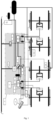
- the reference numerals are as follows: 1-MUD main valve plate, 2-speed synchronization control host, 3-output pressure measuring point of relay valve, 4-electromagnetic exhaust valve, 5-block valve, 6-distribution valve, 7-ECP control host, 8-vehicle monitor, 9-pressure relay, 10-relay valve, 11-speed sensor, 12-disc brake, 13-weighing valve, 14-ECP pre-control chamber, 15-control air cylinder, 16-auxiliary reservoir, 17-train pipe.
- ECP pre-control chamber the air in the ECP pre-control chamber is the pilot air source of the ECP control host and the control air source of the ECP control host.
- the ECP control host controls the exhaust of the train pipe by controlling the air pressure in the air cylinder. Its working principle has been recorded in detail in the publication number: CN201911305491.X , entitled Vehicle electric-pneumatic brake control device, which will not be repeated here.
- Control air cylinder the air in the control air cylinder is the control air source of the distribution valve.
- Distribution valve its role is to control the air inflation and exhaust of the acting air cylinder according to the pressure change in the train pipe, and realize the braking, pressure maintaining or release of the locomotive through the reversing valve and the application valve.
- Train pipe the air pipe used for braking of cross-country trains is a brake pipe, also called train pipe.
- the present invention provides a railway wagon brake control system, comprising a train pipe 17 and a plurality of disc brakes 12 which are used for braking the wheels of a railway wagon, and the braking action is performed on each wheel through the action of the disc brake 12, belonging to a conventional technical means on trains, which will not be repeated here.
- the system also comprises an ECP control host 7 and a distribution valve 6 communicated with the train pipe 17; a block valve 5 is provided between the distribution valve 6 and the train pipe 17, in order to cut off or connect the distribution valve 6 and the train pipe 17; the distribution valve 6 is communicated with a plurality of relay valves 10, each relay valve 10 corresponds to each bogie of the railway wagon, and each disc brake 12 of the same bogie is communicated with the relay valve 10 corresponding to the bogie.
- the same bogie is provided with a relay valve 10, and the output end of the relay valve 10 is connected to two disc brakes 12 through a separate pipeline to break down the air pressure at the output end of the relay valve 10; each disc brake 12 brakes each group of wheels of the bogie, thereby controlling the action consistency and stability of the disc brakes 12.
- the use of relay valve 10 can ensure good decomposition of pressure air.
- the system also comprises a control air cylinder 15 and an auxiliary reservoir 16 which are communicated with the distribution valve 6; each bogie is provided with at least one weighing valve 13, and each weighing valve 13 is respectively communicated with the auxiliary reservoir 16 and the relay valve 10; the auxiliary reservoir 16 provides air source for the operation of each weighing valve 13, and the output of the relay valve 10 is adjusted adaptively according to the output data of the weighing valve 13.
- the weighing valve 13 is used for sensing the weight, and the relay valve 10 adjusts its output according to the output data of the weighing valve 13 to control the output pressure.
- the system further comprises an ECP pre-control chamber 14.
- the ECP pre-control chamber 14 is communicated with the train pipe 17, and the ECP control host 7 controls the air pressure change in the ECP pre-control chamber 14 so as to enable pressure air in the train pipe 7 to be exhausted.
- the ECP pre-control chamber 14, the train pipe 17 and the ECP control host 7 are communicated through a pipeline.
- the ECP control host 7 comprises the on-off solenoid valve disclosed in the prior art ( CN201911305491.X ). This patented technology has disclosed that "the air pressure change in the pre-control chamber acts on the pressure control of the train pipe through the relay valve ("relay valve" in CN201911305491.X , which is different from the "relay valve” in the present embodiment).
- the system also comprises an ECP controller, which can form a network in the local area network and receive remote control. Each ECP controller in the local area network can realize synchronous control of the electrical control signal of the on-off solenoid valve.
- the working principle of the ECP control host 7 controlling the air pressure change in the ECP pre-control chamber 14 so as to enable pressure air in the train pipe to be exhausted will not be further described.
- the pressure air in the train pipe 17 is exhausted, the air pressure in the train pipe 17 will drop, and then it will be induced by the distribution valve 6 to perform subsequent braking action.
- the system also comprises a speed synchronization control host 2, and the speed synchronization control host 2 is installed in the main control cabinet of the railway wagon.
- the speed synchronization control host 2 is connected to a plurality of speed sensors 11, and each speed sensor 11 measures the speed of each wheel of the railway wagon.
- each speed sensor 11 is installed on the axle end of each wheel of the railway wagon, and each speed sensor 11 measures the speed of each wheel by means of gear speed measurement.
- each speed sensor 11 can transmit the speed data of each wheel to the speed synchronization control host 2 which analyzes and processes the speed data, and then output the corresponding control command.
- Each disc brake 12 is communicated with the corresponding relay valve 10 through an independent pipeline to ensure that the air output by the relay valve 10 can be further broken down, in order to meet the air pressure requirements of different disc brakes 12, and each pipeline is provided with an electromagnetic exhaust valve 4.
- Each electromagnetic exhaust valve 4 is respectively connected to the speed synchronization control host 2, and the speed synchronization control host 2 transmits the control command to each electromagnetic exhaust valve 4, in order to further control the air pressure of each disc brake 12.
- the speed synchronization control host 2 controls the speeds of the four groups of wheels of the vehicle by controlling the air pressure of each disc brake 12 during speed regulation, so as to achieve the speed synchronization of the wheels.
- the train pipe 17 is communicated with the pressure relay.
- the circuit of the speed synchronization control host 2 is controlled by the pressure relay 9.
- the pressure relay 9 is connected in series to the power circuit of the speed synchronization control host 2.
- the pressure relay 9 makes corresponding actions according to the pressure changes in the train pipe 17. For example, when the pressure of the train pipe 17 is higher than the set value, the pressure relay 9 will act, in order to turn on the power circuit of the speed synchronization control host 2; the speed synchronization control host 2 is in the working state, and the speed synchronization control host 2 receives the speed data fed back by each speed sensor 11 to control the air volume of each electromagnetic exhaust valve 4.
- the system also comprises an MUD main valve plate 1, and the MUD main valve plate 1 is 910*360*40mm aluminum alloy brazing sheet; the weighing valve 13 and distribution valve 6 are installed on one side of the MUD main valve plate 1, and the ECP control host 7, ECP pre-control chamber 14, control air cylinder 15, block valve 5, pressure relay 9 and each electromagnetic exhaust valve 4 are installed on the other side, in order to finally realize integrated plate type structural design of the whole system.
- the train pipe 17, the control air cylinder 15, the output port of the distribution valve 6, the output port of the relay valve 10 and the ECP pre-control air cylinder are connected respectively through the pipeline interface on the MUD main valve plate 1.
- the specific pipeline layout can be adaptively designed according to the actual situation, and its pipeline connection relationship is as shown in the system framework diagram in Fig. 1 .
- the system also comprises a plurality of pressure sensors connected to the ECP control host 7, wherein each pressure sensor measures the pressure of the train pipe 17, the pressure of the control air cylinder 15, the output pressure of the distribution valve 6 and the output pressure of the relay valve 10 (i.e., output pressure measuring point of the relay valve in Fig. 1 ).
- the ECP control host 7 continuously measures the pressure of the train pipe 17, the pressure of control air cylinder 15, the output pressure of the distribution valve 6 and the output pressure of the relay valve 10 through the pressure sensor, and judges whether the vehicle is out of order according to the correspondence of each output pressure.
- the pneumatic brake fault monitored by the ECP control host 7 is transmitted to an external device through an RS485 communication line, so that the staff can repair in time.
- the working principle of the railway wagon brake control system in the present embodiment is as follows: After the block valve 5 is opened and the speed synchronization control host 2 and ECP control host 7 are powered on, the whole brake system can work normally.
- the whole railway wagon is provided with a plurality of ECP control hosts 7, and each ECP control host 7 has wireless communication function. All ECP control hosts 7 in the train are in the same local area network, and the control commands generated by the ECP control hosts 7 and the vehicle fault information monitored by the vehicle monitor 10 are wirelessly transmitted in the local area network.
- the ECP control host 7 synchronously implements the air exhaust action in the train pipe 17 through a wireless network, and the distribution valve 6 senses the pressure drop in the train pipe 17, and then further controls the air in the auxiliary reservoir 16 to flow to the disc brake 12 to complete the output air pressure control;
- the relay valve 10 further breaks down and controls the output pressure according to the weight of the vehicle body fed back by the weighing valve 13 and outputs it to the disc brake 12 through the pipeline;
- the speed sensor 11 at the axle end collects the wheel speed, and the speed synchronization control host 2 controls the electromagnetic exhaust valve 4 according to the wheel speed data to further break down and control the output pressure to the disc brake 12;
- the output air pressure is controlled finally through the ECP control host 7 and the distribution valve 6 to sense the pressure change of the train pipe 17, and therefore the purposes of being high in braking synchronism, good in deceleration consistency and capable of achieving real-time self-monitoring are achieved.
- the present embodiment provides a railway wagon brake control method, which is applied in the railway wagon brake control system, and the control method comprises:
- the ECP control host 7 continuously measures the pressure of the train pipe 17, the pressure of the control air cylinder 15, the output pressure of the distribution valve 6 and the output pressure of the relay valve 10 through the pressure sensor, and judges whether the vehicle is out of order according to the correspondence of each output pressure.
- the monitored pneumatic brake fault is transmitted to an external device through an RS485 communication line, so that the staff can repair in time.
- all functional units in each embodiment of the present application can be integrated in one processing module, or all units can also physically exist independently, or two or over units are integrated in one module.
- the module can be integrated in the form of hardware, and can also be integrated in the form of software function module. If the module is integrated in the form of software function module and used as an independent product for sale or use, it can also be stored in a computer-readable storage medium.
- the storage medium mentioned above can be read only memory, disk or optical disk, etc.
Landscapes
- Engineering & Computer Science (AREA)
- Mechanical Engineering (AREA)
- Transportation (AREA)
- Regulating Braking Force (AREA)
- Braking Systems And Boosters (AREA)
- Valves And Accessory Devices For Braking Systems (AREA)
Claims (10)
- Eisenbahnwaggon-Bremssteuersystem, umfassend ein Zugrohr (17) und eine Vielzahl von Scheibenbremsen (12), die zum Bremsen der Räder eines Eisenbahnwaggons verwendet werden, wobei das System ferner einen ECP-Steuerhost (7) und ein Verteilerventil (6) umfasst, das mit dem Zugrohr (17) in Verbindung steht; wobei das Verteilerventil mit einer Vielzahl von Relaisventilen in Verbindung steht, jedes Relaisventil jedem Drehgestell des Eisenbahnwaggons entspricht und jede Scheibenbremse (12) desselben Drehgestells mit dem Relaisventil, das dem Drehgestell entspricht, in Verbindung steht;wobei das System auch einen Steuerluftzylinder (15) und einen Hilfsbehälter (16) umfasst, die mit dem Verteilerventil (6) in Verbindung stehen; jedes Drehgestell mit mindestens einem Wiegeventil (13) versehen ist, und jedes Wiegeventil (13) jeweils mit dem Hilfsbehälter (16) und dem Relaisventil in Verbindung steht;dadurch gekennzeichnet, dassdas System ferner eine ECP-Vorsteuerkammer (14) umfasst, die ECP-Vorsteuerkammer mit dem Zugrohr in Verbindung steht und der ECP-Steuerhost (7) die Luftdruckänderung in der ECP-Vorsteuerkammer (14) steuert, so dass die Druckluft in dem Zugrohr abgelassen werden kann;das System ferner einen Drehzahlsynchronisierungs-Steuerhost (2) umfasst, wobei der Drehzahlsynchronisierungs-Steuerhost mit einer Vielzahl von Drehzahlsensoren (11) verbunden ist, und jeder Drehzahlsensor die Drehzahl jedes Rades des Eisenbahnwaggons misst.
- Eisenbahnwaggon-Bremssteuersystem nach Anspruch 1, dadurch gekennzeichnet, dass die Drehzahlsensoren (11) an den Achsenden jedes Rades des Eisenbahnwaggons installiert sind.
- Eisenbahnwaggon-Bremssteuersystem nach Anspruch 1, dadurch gekennzeichnet, dass die Scheibenbremse (12) über eine unabhängige Rohrleitung mit dem entsprechenden Relaisventil in Verbindung steht und jede Rohrleitung mit einem elektromagnetischen Auslassventil (4) versehen ist, das jeweils mit dem Drehzahlsynchronisierungs-Steuerhost (2) verbunden ist.
- Eisenbahnwaggon-Bremssteuersystem nach Anspruch 3, dadurch gekennzeichnet, dass das Zugrohr (17) mit einem Druckrelais (10) in Verbindung steht, das den Stromkreis jedes elektromagnetischen Auslassventils (4) steuert.
- Eisenbahnwaggon-Bremssteuersystem nach Anspruch 4, dadurch gekennzeichnet, dass es auch eine MUD-Hauptventilplatte (1) umfasst, wobei das Relaisventil und das Verteilerventil (6) auf einer Seite der MUD-Hauptventilplatte (1) installiert sind und der ECP-Steuerhost (7), die ECP-Vorsteuerkammer (14), der Steuerluftzylinder (15), das Druckrelais (10) und jedes elektromagnetische Auslassventil (4) auf der anderen Seite installiert sind.
- Eisenbahnwaggon-Bremssteuersystem nach Anspruch 1, dadurch gekennzeichnet, dass zwischen dem Verteilerventil (6) und dem Zugrohr (17) ein Sperrventil (5) vorgesehen ist.
- Eisenbahnwaggon-Bremssteuersystem nach Anspruch 1, dadurch gekennzeichnet, dass es auch eine Vielzahl von Drucksensoren umfasst, die mit dem ECP-Steuerhost (7) verbunden sind, wobei jeder Drucksensor den Druck des Zugrohrs (17), den Druck des Steuerluftzylinders (15), den Ausgangsdruck des Verteilerventils (6) und den Ausgangsdruck des Relaisventils misst.
- Eisenbahnwaggon-Bremssteuersystem nach Anspruch 1, dadurch gekennzeichnet, dass der ECP-Steuerhost (7) über eine RS485-Kommunikationsleitung an eine externe Vorrichtung übertragen wird und der Drehzahlsynchronisierungs-Steuerhost (2) im Hauptschaltschrank des Eisenbahnwaggons installiert ist.
- Eisenbahnwaggon-Bremssteuerungsverfahren, dadurch gekennzeichnet, dass das Verfahren in dem Eisenbahnwaggon-Bremssteuerungssystem nach einem der Ansprüche 1 bis 8 angewendet wird, und das Verfahren Folgendes umfasst:der ECP-Steuerhost (7) steuert die Luftdruckänderung in der ECP-Vorsteuerkammer (14), so dass die Druckluft in dem Zugrohr (17) abgelassen werden kann;nachdem der Druck in dem Zugrohr reduziert wurde, wird die Luft im Hilfsbehälter (16) so gesteuert, dass sie durch das Verteilerventil (6) zu jedem Relaisventil strömt;jedes Relaisventil teilt seinen Ausgangsdruck an jeder Scheibenbremse (12) entsprechend dem Ausgang jedes Wiegeventils (13) auf; undjede Scheibenbremse führt einen Bremsvorgang durch;wobei das Verfahren ferner Folgendes umfasst:Drehzahlsensoren (11) sind an den Achsenden jedes Rades des Eisenbahnwaggons konfiguriert, und die Drehzahl jedes Rades wird vom Drehzahlsensor gemessen und an den Drehzahlsynchronisierungs-Steuerhost (2) zurückgemeldet;ein elektromagnetisches Auslassventil (4) ist an der Verbindungsleitung zwischen dem Relaisventil und jeder Scheibenbremse (12) vorgesehen; undder Drehzahlsynchronisierungs-Steuerhost steuert das entsprechende elektromagnetische Auslassventil (4) entsprechend den Drehzahldaten jedes Rades, um den Ausgangsdruck zu jeder Scheibenbremse zu steuern.
- Eisenbahnwaggon-Bremssteuerungsverfahren nach Anspruch 9, dadurch gekennzeichnet, dass der ECP-Steuerhost (7) kontinuierlich den Druck des Zugrohrs (17), den Druck des Steuerluftzylinders (15), den Ausgangsdruck des Verteilerventils (6) und den Ausgangsdruck des Relaisventils durch den Drucksensor misst und entsprechend der Übereinstimmung jedes Ausgangsdrucks bestimmt, ob das Fahrzeug außer Betrieb ist.
Applications Claiming Priority (1)
| Application Number | Priority Date | Filing Date | Title |
|---|---|---|---|
| PCT/CN2020/105138 WO2022021055A1 (zh) | 2020-07-28 | 2020-07-28 | 一种铁路货车制动控制系统及控制方法 |
Publications (3)
| Publication Number | Publication Date |
|---|---|
| EP4186757A1 EP4186757A1 (de) | 2023-05-31 |
| EP4186757A4 EP4186757A4 (de) | 2023-09-27 |
| EP4186757B1 true EP4186757B1 (de) | 2025-06-04 |
Family
ID=80037951
Family Applications (1)
| Application Number | Title | Priority Date | Filing Date |
|---|---|---|---|
| EP20946610.1A Active EP4186757B1 (de) | 2020-07-28 | 2020-07-28 | Bremssteuersystem für eisenbahnwaggons und steuerungsverfahren |
Country Status (3)
| Country | Link |
|---|---|
| EP (1) | EP4186757B1 (de) |
| AU (1) | AU2020460690B2 (de) |
| WO (1) | WO2022021055A1 (de) |
Families Citing this family (3)
| Publication number | Priority date | Publication date | Assignee | Title |
|---|---|---|---|---|
| CN112781897A (zh) * | 2020-12-23 | 2021-05-11 | 神华铁路装备有限责任公司 | 安装工装及列车试验系统 |
| CN115923856A (zh) * | 2022-11-30 | 2023-04-07 | 宝鸡中车时代工程机械有限公司 | 接触网绝缘子冲洗车 |
| CN116279374A (zh) * | 2023-04-07 | 2023-06-23 | 西南交通大学希望学院 | 一种列车制动管路维护系统 |
Family Cites Families (9)
| Publication number | Priority date | Publication date | Assignee | Title |
|---|---|---|---|---|
| AU2003302618A1 (en) * | 2002-11-29 | 2004-06-23 | Tecnologie Diesel E Sistemi Frenanti S.P.A. | Hydraulically-actuated parking brake with mechanical blocking means |
| WO2006122374A1 (en) * | 2005-05-20 | 2006-11-23 | Queensland Rail | Electronically controlled pneumatic brake system |
| CN202017720U (zh) * | 2011-03-02 | 2011-10-26 | 中国铁道科学研究院机车车辆研究所 | 一种用于铁路货车的盘形制动装置 |
| CN102152800B (zh) * | 2011-03-02 | 2013-06-05 | 中国铁道科学研究院机车车辆研究所 | 一种铁路货车制动系统 |
| EP2952405B1 (de) * | 2013-01-30 | 2021-10-06 | Nabtesco Corporation | Schienenfahrzeugbremsvorrichtung, schienenfahrzeug und schienenfahrzeugherstellung |
| DE102014113056A1 (de) * | 2014-09-10 | 2016-03-10 | Knorr-Bremse Systeme für Nutzfahrzeuge GmbH | Scheibenbremsanlage |
| CN110949350B (zh) * | 2019-12-18 | 2024-10-08 | 眉山中车制动科技股份有限公司 | 一种电空制动用控制装置及制动控制系统 |
| CN111422217B (zh) * | 2020-04-29 | 2023-08-29 | 吕振国 | 一种用于盘形制动机车恢复粘着力的方法 |
| CN111873970B (zh) * | 2020-07-28 | 2024-08-27 | 眉山中车制动科技股份有限公司 | 一种铁路货车制动控制系统及控制方法 |
-
2020
- 2020-07-28 WO PCT/CN2020/105138 patent/WO2022021055A1/zh not_active Ceased
- 2020-07-28 EP EP20946610.1A patent/EP4186757B1/de active Active
- 2020-07-28 AU AU2020460690A patent/AU2020460690B2/en active Active
Also Published As
| Publication number | Publication date |
|---|---|
| EP4186757A1 (de) | 2023-05-31 |
| WO2022021055A1 (zh) | 2022-02-03 |
| AU2020460690B2 (en) | 2025-01-30 |
| AU2020460690A1 (en) | 2023-03-16 |
| EP4186757A4 (de) | 2023-09-27 |
Similar Documents
| Publication | Publication Date | Title |
|---|---|---|
| AU2020460690B2 (en) | Railway wagon brake control system and control method | |
| CN111873970B (zh) | 一种铁路货车制动控制系统及控制方法 | |
| US8190311B2 (en) | Adaptive brake scheme during a locomotive distributed power communication loss | |
| CN109572654B (zh) | 一种基于牵引制动融合控制系统的冲击率控制方法 | |
| AU762654B2 (en) | Railway emulation brake | |
| CN101941382B (zh) | 基于无线通信的铁路货车电空制动系统和方法 | |
| CN110194135B (zh) | 适用于3至5节车厢的铰接式胶轮无轨电车制动系统 | |
| CN101508287B (zh) | 基于单轴控制的具有故障互补控制的电空制动方法及系统 | |
| JP2002528329A (ja) | 鉄道車両用ブレーキシステム | |
| CN114572270B (zh) | 轴控式制动控制系统及轨道交通车辆 | |
| CN107298111A (zh) | 一种用于货运列车的空电制动系统 | |
| AU2012380356A1 (en) | Train control system | |
| CN105774785A (zh) | 轨道车辆空气制动系统 | |
| AU2002353994B2 (en) | Locomotive brake pipe valve cut-out failure detection and correction | |
| CN113120024A (zh) | 轨道车辆制动系统纯空气紧急制动控制方法及控制装置 | |
| CN110949350A (zh) | 一种电空制动用控制装置及制动控制系统 | |
| EP4011728B1 (de) | Bremssteuerungssystem für ein schienenfahrzeug | |
| CN212243320U (zh) | 一种铁路货车制动控制系统 | |
| CN108944879A (zh) | 一种制动方法、制动装置及铁路货车 | |
| CN106043257B (zh) | 一种单元内施行制动力分配的架控式制动系统及其制动控制方法 | |
| WO2026031344A1 (zh) | 轨道交通车辆制动控制系统及其控制方法、轨道交通车辆 | |
| CN216359959U (zh) | 一种半动力轨道车辆动轴制动互锁控制装置 | |
| JP2025506949A (ja) | 軌道車両用のブレーキシステムおよびそのようなブレーキシステムを駆動制御するための方法 | |
| CN113928291A (zh) | 一种半动力轨道车辆动轴制动互锁控制装置及控制方法 | |
| JPH1044964A (ja) | 鉄道車両用ブレーキ装置 |
Legal Events
| Date | Code | Title | Description |
|---|---|---|---|
| STAA | Information on the status of an ep patent application or granted ep patent |
Free format text: STATUS: THE INTERNATIONAL PUBLICATION HAS BEEN MADE |
|
| PUAI | Public reference made under article 153(3) epc to a published international application that has entered the european phase |
Free format text: ORIGINAL CODE: 0009012 |
|
| STAA | Information on the status of an ep patent application or granted ep patent |
Free format text: STATUS: REQUEST FOR EXAMINATION WAS MADE |
|
| 17P | Request for examination filed |
Effective date: 20230223 |
|
| AK | Designated contracting states |
Kind code of ref document: A1 Designated state(s): AL AT BE BG CH CY CZ DE DK EE ES FI FR GB GR HR HU IE IS IT LI LT LU LV MC MK MT NL NO PL PT RO RS SE SI SK SM TR |
|
| STAA | Information on the status of an ep patent application or granted ep patent |
Free format text: STATUS: EXAMINATION IS IN PROGRESS |
|
| A4 | Supplementary search report drawn up and despatched |
Effective date: 20230824 |
|
| RIC1 | Information provided on ipc code assigned before grant |
Ipc: B61H 13/00 20060101ALI20230818BHEP Ipc: B60T 17/22 20060101ALI20230818BHEP Ipc: B60T 13/66 20060101ALI20230818BHEP Ipc: B60T 8/18 20060101ALI20230818BHEP Ipc: B60T 8/58 20060101AFI20230818BHEP |
|
| 17Q | First examination report despatched |
Effective date: 20230905 |
|
| DAV | Request for validation of the european patent (deleted) | ||
| DAX | Request for extension of the european patent (deleted) | ||
| GRAP | Despatch of communication of intention to grant a patent |
Free format text: ORIGINAL CODE: EPIDOSNIGR1 |
|
| STAA | Information on the status of an ep patent application or granted ep patent |
Free format text: STATUS: GRANT OF PATENT IS INTENDED |
|
| RIC1 | Information provided on ipc code assigned before grant |
Ipc: B61H 13/00 20060101ALI20250128BHEP Ipc: B60T 17/22 20060101ALI20250128BHEP Ipc: B60T 13/66 20060101ALI20250128BHEP Ipc: B60T 8/18 20060101ALI20250128BHEP Ipc: B60T 8/58 20060101AFI20250128BHEP |
|
| INTG | Intention to grant announced |
Effective date: 20250214 |
|
| GRAS | Grant fee paid |
Free format text: ORIGINAL CODE: EPIDOSNIGR3 |
|
| GRAA | (expected) grant |
Free format text: ORIGINAL CODE: 0009210 |
|
| STAA | Information on the status of an ep patent application or granted ep patent |
Free format text: STATUS: THE PATENT HAS BEEN GRANTED |
|
| AK | Designated contracting states |
Kind code of ref document: B1 Designated state(s): AL AT BE BG CH CY CZ DE DK EE ES FI FR GB GR HR HU IE IS IT LI LT LU LV MC MK MT NL NO PL PT RO RS SE SI SK SM TR |
|
| REG | Reference to a national code |
Ref country code: GB Ref legal event code: FG4D |
|
| REG | Reference to a national code |
Ref country code: CH Ref legal event code: EP |
|
| REG | Reference to a national code |
Ref country code: DE Ref legal event code: R096 Ref document number: 602020052497 Country of ref document: DE |
|
| REG | Reference to a national code |
Ref country code: IE Ref legal event code: FG4D |
|
| REG | Reference to a national code |
Ref country code: NL Ref legal event code: MP Effective date: 20250604 |
|
| PG25 | Lapsed in a contracting state [announced via postgrant information from national office to epo] |
Ref country code: FI Free format text: LAPSE BECAUSE OF FAILURE TO SUBMIT A TRANSLATION OF THE DESCRIPTION OR TO PAY THE FEE WITHIN THE PRESCRIBED TIME-LIMIT Effective date: 20250604 Ref country code: ES Free format text: LAPSE BECAUSE OF FAILURE TO SUBMIT A TRANSLATION OF THE DESCRIPTION OR TO PAY THE FEE WITHIN THE PRESCRIBED TIME-LIMIT Effective date: 20250604 |
|
| PGFP | Annual fee paid to national office [announced via postgrant information from national office to epo] |
Ref country code: DE Payment date: 20250728 Year of fee payment: 6 |
|
| REG | Reference to a national code |
Ref country code: LT Ref legal event code: MG9D |
|
| PG25 | Lapsed in a contracting state [announced via postgrant information from national office to epo] |
Ref country code: GR Free format text: LAPSE BECAUSE OF FAILURE TO SUBMIT A TRANSLATION OF THE DESCRIPTION OR TO PAY THE FEE WITHIN THE PRESCRIBED TIME-LIMIT Effective date: 20250905 Ref country code: NO Free format text: LAPSE BECAUSE OF FAILURE TO SUBMIT A TRANSLATION OF THE DESCRIPTION OR TO PAY THE FEE WITHIN THE PRESCRIBED TIME-LIMIT Effective date: 20250904 |
|
| PG25 | Lapsed in a contracting state [announced via postgrant information from national office to epo] |
Ref country code: PL Free format text: LAPSE BECAUSE OF FAILURE TO SUBMIT A TRANSLATION OF THE DESCRIPTION OR TO PAY THE FEE WITHIN THE PRESCRIBED TIME-LIMIT Effective date: 20250604 |
|
| PG25 | Lapsed in a contracting state [announced via postgrant information from national office to epo] |
Ref country code: BG Free format text: LAPSE BECAUSE OF FAILURE TO SUBMIT A TRANSLATION OF THE DESCRIPTION OR TO PAY THE FEE WITHIN THE PRESCRIBED TIME-LIMIT Effective date: 20250604 |
|
| PG25 | Lapsed in a contracting state [announced via postgrant information from national office to epo] |
Ref country code: HR Free format text: LAPSE BECAUSE OF FAILURE TO SUBMIT A TRANSLATION OF THE DESCRIPTION OR TO PAY THE FEE WITHIN THE PRESCRIBED TIME-LIMIT Effective date: 20250604 |
|
| PG25 | Lapsed in a contracting state [announced via postgrant information from national office to epo] |
Ref country code: RS Free format text: LAPSE BECAUSE OF FAILURE TO SUBMIT A TRANSLATION OF THE DESCRIPTION OR TO PAY THE FEE WITHIN THE PRESCRIBED TIME-LIMIT Effective date: 20250904 |
|
| PG25 | Lapsed in a contracting state [announced via postgrant information from national office to epo] |
Ref country code: LV Free format text: LAPSE BECAUSE OF FAILURE TO SUBMIT A TRANSLATION OF THE DESCRIPTION OR TO PAY THE FEE WITHIN THE PRESCRIBED TIME-LIMIT Effective date: 20250604 |
|
| PG25 | Lapsed in a contracting state [announced via postgrant information from national office to epo] |
Ref country code: NL Free format text: LAPSE BECAUSE OF FAILURE TO SUBMIT A TRANSLATION OF THE DESCRIPTION OR TO PAY THE FEE WITHIN THE PRESCRIBED TIME-LIMIT Effective date: 20250604 |
|
| PG25 | Lapsed in a contracting state [announced via postgrant information from national office to epo] |
Ref country code: PT Free format text: LAPSE BECAUSE OF FAILURE TO SUBMIT A TRANSLATION OF THE DESCRIPTION OR TO PAY THE FEE WITHIN THE PRESCRIBED TIME-LIMIT Effective date: 20251006 |
|
| REG | Reference to a national code |
Ref country code: AT Ref legal event code: MK05 Ref document number: 1800072 Country of ref document: AT Kind code of ref document: T Effective date: 20250604 |
|
| PG25 | Lapsed in a contracting state [announced via postgrant information from national office to epo] |
Ref country code: IS Free format text: LAPSE BECAUSE OF FAILURE TO SUBMIT A TRANSLATION OF THE DESCRIPTION OR TO PAY THE FEE WITHIN THE PRESCRIBED TIME-LIMIT Effective date: 20251004 |
|
| PG25 | Lapsed in a contracting state [announced via postgrant information from national office to epo] |
Ref country code: SM Free format text: LAPSE BECAUSE OF FAILURE TO SUBMIT A TRANSLATION OF THE DESCRIPTION OR TO PAY THE FEE WITHIN THE PRESCRIBED TIME-LIMIT Effective date: 20250604 Ref country code: AT Free format text: LAPSE BECAUSE OF FAILURE TO SUBMIT A TRANSLATION OF THE DESCRIPTION OR TO PAY THE FEE WITHIN THE PRESCRIBED TIME-LIMIT Effective date: 20250604 |
|
| PG25 | Lapsed in a contracting state [announced via postgrant information from national office to epo] |
Ref country code: CZ Free format text: LAPSE BECAUSE OF FAILURE TO SUBMIT A TRANSLATION OF THE DESCRIPTION OR TO PAY THE FEE WITHIN THE PRESCRIBED TIME-LIMIT Effective date: 20250604 |
|
| PG25 | Lapsed in a contracting state [announced via postgrant information from national office to epo] |
Ref country code: EE Free format text: LAPSE BECAUSE OF FAILURE TO SUBMIT A TRANSLATION OF THE DESCRIPTION OR TO PAY THE FEE WITHIN THE PRESCRIBED TIME-LIMIT Effective date: 20250604 |
|
| PG25 | Lapsed in a contracting state [announced via postgrant information from national office to epo] |
Ref country code: SK Free format text: LAPSE BECAUSE OF FAILURE TO SUBMIT A TRANSLATION OF THE DESCRIPTION OR TO PAY THE FEE WITHIN THE PRESCRIBED TIME-LIMIT Effective date: 20250604 |
|
| PG25 | Lapsed in a contracting state [announced via postgrant information from national office to epo] |
Ref country code: IT Free format text: LAPSE BECAUSE OF FAILURE TO SUBMIT A TRANSLATION OF THE DESCRIPTION OR TO PAY THE FEE WITHIN THE PRESCRIBED TIME-LIMIT Effective date: 20250604 |
|
| REG | Reference to a national code |
Ref country code: CH Ref legal event code: H13 Free format text: ST27 STATUS EVENT CODE: U-0-0-H10-H13 (AS PROVIDED BY THE NATIONAL OFFICE) Effective date: 20260224 |
|
| REG | Reference to a national code |
Ref country code: DE Ref legal event code: R097 Ref document number: 602020052497 Country of ref document: DE |
|
| PG25 | Lapsed in a contracting state [announced via postgrant information from national office to epo] |
Ref country code: RO Free format text: LAPSE BECAUSE OF FAILURE TO SUBMIT A TRANSLATION OF THE DESCRIPTION OR TO PAY THE FEE WITHIN THE PRESCRIBED TIME-LIMIT Effective date: 20250604 |
|
| PG25 | Lapsed in a contracting state [announced via postgrant information from national office to epo] |
Ref country code: LU Free format text: LAPSE BECAUSE OF NON-PAYMENT OF DUE FEES Effective date: 20250728 |
|
| REG | Reference to a national code |
Ref country code: BE Ref legal event code: MM Effective date: 20250731 |
|
| PG25 | Lapsed in a contracting state [announced via postgrant information from national office to epo] |
Ref country code: MC Free format text: LAPSE BECAUSE OF FAILURE TO SUBMIT A TRANSLATION OF THE DESCRIPTION OR TO PAY THE FEE WITHIN THE PRESCRIBED TIME-LIMIT Effective date: 20250604 |
|
| PLBE | No opposition filed within time limit |
Free format text: ORIGINAL CODE: 0009261 |
|
| STAA | Information on the status of an ep patent application or granted ep patent |
Free format text: STATUS: NO OPPOSITION FILED WITHIN TIME LIMIT |
|
| PG25 | Lapsed in a contracting state [announced via postgrant information from national office to epo] |
Ref country code: DK Free format text: LAPSE BECAUSE OF FAILURE TO SUBMIT A TRANSLATION OF THE DESCRIPTION OR TO PAY THE FEE WITHIN THE PRESCRIBED TIME-LIMIT Effective date: 20250604 |
|
| PG25 | Lapsed in a contracting state [announced via postgrant information from national office to epo] |
Ref country code: BE Free format text: LAPSE BECAUSE OF NON-PAYMENT OF DUE FEES Effective date: 20250731 |
|
| REG | Reference to a national code |
Ref country code: CH Ref legal event code: L10 Free format text: ST27 STATUS EVENT CODE: U-0-0-L10-L00 (AS PROVIDED BY THE NATIONAL OFFICE) Effective date: 20260416 |
|
| PG25 | Lapsed in a contracting state [announced via postgrant information from national office to epo] |
Ref country code: CH Free format text: LAPSE BECAUSE OF NON-PAYMENT OF DUE FEES Effective date: 20250731 |
|
| 26N | No opposition filed |
Effective date: 20260305 |