EP4186757B1 - Railway wagon brake control system and control method - Google Patents
Railway wagon brake control system and control method Download PDFInfo
- Publication number
- EP4186757B1 EP4186757B1 EP20946610.1A EP20946610A EP4186757B1 EP 4186757 B1 EP4186757 B1 EP 4186757B1 EP 20946610 A EP20946610 A EP 20946610A EP 4186757 B1 EP4186757 B1 EP 4186757B1
- Authority
- EP
- European Patent Office
- Prior art keywords
- valve
- pressure
- control
- ecp
- railway wagon
- Prior art date
- Legal status (The legal status is an assumption and is not a legal conclusion. Google has not performed a legal analysis and makes no representation as to the accuracy of the status listed.)
- Active
Links
Images


Classifications
-
- B—PERFORMING OPERATIONS; TRANSPORTING
- B60—VEHICLES IN GENERAL
- B60T—VEHICLE BRAKE CONTROL SYSTEMS OR PARTS THEREOF; BRAKE CONTROL SYSTEMS OR PARTS THEREOF, IN GENERAL; ARRANGEMENT OF BRAKING ELEMENTS ON VEHICLES IN GENERAL; PORTABLE DEVICES FOR PREVENTING UNWANTED MOVEMENT OF VEHICLES; VEHICLE MODIFICATIONS TO FACILITATE COOLING OF BRAKES
- B60T17/00—Component parts, details, or accessories of power brake systems not covered by groups B60T8/00, B60T13/00 or B60T15/00, or presenting other characteristic features
- B60T17/18—Safety devices; Monitoring
- B60T17/22—Devices for monitoring or checking brake systems; Signal devices
- B60T17/228—Devices for monitoring or checking brake systems; Signal devices for railway vehicles
-
- B—PERFORMING OPERATIONS; TRANSPORTING
- B60—VEHICLES IN GENERAL
- B60T—VEHICLE BRAKE CONTROL SYSTEMS OR PARTS THEREOF; BRAKE CONTROL SYSTEMS OR PARTS THEREOF, IN GENERAL; ARRANGEMENT OF BRAKING ELEMENTS ON VEHICLES IN GENERAL; PORTABLE DEVICES FOR PREVENTING UNWANTED MOVEMENT OF VEHICLES; VEHICLE MODIFICATIONS TO FACILITATE COOLING OF BRAKES
- B60T13/00—Transmitting braking action from initiating means to ultimate brake actuator with power assistance or drive; Brake systems incorporating such transmitting means, e.g. air-pressure brake systems
- B60T13/10—Transmitting braking action from initiating means to ultimate brake actuator with power assistance or drive; Brake systems incorporating such transmitting means, e.g. air-pressure brake systems with fluid assistance, drive, or release
- B60T13/66—Electrical control in fluid-pressure brake systems
- B60T13/665—Electrical control in fluid-pressure brake systems the systems being specially adapted for transferring two or more command signals, e.g. railway systems
-
- B—PERFORMING OPERATIONS; TRANSPORTING
- B60—VEHICLES IN GENERAL
- B60T—VEHICLE BRAKE CONTROL SYSTEMS OR PARTS THEREOF; BRAKE CONTROL SYSTEMS OR PARTS THEREOF, IN GENERAL; ARRANGEMENT OF BRAKING ELEMENTS ON VEHICLES IN GENERAL; PORTABLE DEVICES FOR PREVENTING UNWANTED MOVEMENT OF VEHICLES; VEHICLE MODIFICATIONS TO FACILITATE COOLING OF BRAKES
- B60T8/00—Arrangements for adjusting wheel-braking force to meet varying vehicular or ground-surface conditions, e.g. limiting or varying distribution of braking force
- B60T8/18—Arrangements for adjusting wheel-braking force to meet varying vehicular or ground-surface conditions, e.g. limiting or varying distribution of braking force responsive to vehicle weight or load, e.g. load distribution
- B60T8/1893—Arrangements for adjusting wheel-braking force to meet varying vehicular or ground-surface conditions, e.g. limiting or varying distribution of braking force responsive to vehicle weight or load, e.g. load distribution especially adapted for railway vehicles
-
- B—PERFORMING OPERATIONS; TRANSPORTING
- B61—RAILWAYS
- B61H—BRAKES OR OTHER RETARDING DEVICES SPECIALLY ADAPTED FOR RAIL VEHICLES; ARRANGEMENT OR DISPOSITION THEREOF IN RAIL VEHICLES
- B61H13/00—Actuating rail-vehicle brakes
Definitions
- the present invention belongs to the technical field of train brake control, in particular to a railway wagon brake control system and control method.
- Vehicle pneumatic brake is one of the brake modes of railway locomotives and vehicles, which is to use compressed air as the braking motive power to control the train braking by changing the pressure of compressed air.
- the purpose of the present invention is to provide a railway wagon brake control system and a control method to achieve the purposes of being high in braking synchronism, good in deceleration consistency and capable of achieving real-time self-monitoring, consequently to effectively improve the safety and service efficiency of railway wagons.
- a railway wagon brake control system comprising a train pipe and a plurality of disc brakes which are used for braking the wheels of a railway wagon, and also comprising an ECP control host and a distribution valve communicated with the train pipe;
- the distribution valve is communicated with a plurality of relay valves, each relay valve corresponds to each bogie of the rail wagon, and each disc brake of the same bogie is communicated with the relay valve corresponding to the bogie;
- the system also comprises a speed synchronization control host, wherein the speed synchronization control host is connected to a plurality of speed sensors, and each speed sensor measures the speed of each wheel of the railway wagon.
- the speed sensors are installed on the axle ends of each wheel of the railway wagon, and the transmission between the speed sensor and the wheel is realized by means of gear speed measurement.
- the disc brake is communicated with the corresponding relay valve through an independent pipeline, and each pipeline is provided with an electromagnetic exhaust valve, which is respectively connected to the speed synchronization control host; the pressure air from the relay valve to each disc brake is further broken down by controlling the exhaust air volume of each electromagnetic exhaust valve.
- train pipe is communicated with a pressure relay, which controls the circuit of each electromagnetic exhaust valve.
- the system also comprises an MUD main valve plate, wherein the relay valve and distribution valve are installed on one side of the MUD main valve plate, and the ECP control host, ECP pre-control chamber, control air cylinder, pressure relay and each electromagnetic exhaust valve are installed on the other side, in order to realize integrated design of the whole system.
- a block valve is provided between the distribution valve and the train pipe, in order to cut off or connect the distribution valve and the train pipe.
- the system also comprises a plurality of pressure sensors connected to the ECP control host, wherein each pressure sensor measures the pressure of the train pipe, the pressure of the control air cylinder, the output pressure of the distribution valve and the output pressure of the relay valve, in order to judge whether the pneumatic brake system of the vehicle is out of order.
- the ECP control host is transmitted to an external device through an RS485 communication line, and the speed synchronization control host is installed in the main control cabinet of the railway wagon, in order to transmit and feed back fault information in time.
- the present invention also provides a railway wagon brake control method, which is applied in the railway wagon brake control system, and the method comprises:
- the method also comprises:
- the ECP control host continuously measures the pressure of the train pipe, the pressure of the control air cylinder, the output pressure of the distribution valve and the output pressure of the relay valve through the pressure sensor, and judges whether the vehicle is out of order according to the correspondence of each output pressure.
- the reference numerals are as follows: 1-MUD main valve plate, 2-speed synchronization control host, 3-output pressure measuring point of relay valve, 4-electromagnetic exhaust valve, 5-block valve, 6-distribution valve, 7-ECP control host, 8-vehicle monitor, 9-pressure relay, 10-relay valve, 11-speed sensor, 12-disc brake, 13-weighing valve, 14-ECP pre-control chamber, 15-control air cylinder, 16-auxiliary reservoir, 17-train pipe.
- ECP pre-control chamber the air in the ECP pre-control chamber is the pilot air source of the ECP control host and the control air source of the ECP control host.
- the ECP control host controls the exhaust of the train pipe by controlling the air pressure in the air cylinder. Its working principle has been recorded in detail in the publication number: CN201911305491.X , entitled Vehicle electric-pneumatic brake control device, which will not be repeated here.
- Control air cylinder the air in the control air cylinder is the control air source of the distribution valve.
- Distribution valve its role is to control the air inflation and exhaust of the acting air cylinder according to the pressure change in the train pipe, and realize the braking, pressure maintaining or release of the locomotive through the reversing valve and the application valve.
- Train pipe the air pipe used for braking of cross-country trains is a brake pipe, also called train pipe.
- the present invention provides a railway wagon brake control system, comprising a train pipe 17 and a plurality of disc brakes 12 which are used for braking the wheels of a railway wagon, and the braking action is performed on each wheel through the action of the disc brake 12, belonging to a conventional technical means on trains, which will not be repeated here.
- the system also comprises an ECP control host 7 and a distribution valve 6 communicated with the train pipe 17; a block valve 5 is provided between the distribution valve 6 and the train pipe 17, in order to cut off or connect the distribution valve 6 and the train pipe 17; the distribution valve 6 is communicated with a plurality of relay valves 10, each relay valve 10 corresponds to each bogie of the railway wagon, and each disc brake 12 of the same bogie is communicated with the relay valve 10 corresponding to the bogie.
- the same bogie is provided with a relay valve 10, and the output end of the relay valve 10 is connected to two disc brakes 12 through a separate pipeline to break down the air pressure at the output end of the relay valve 10; each disc brake 12 brakes each group of wheels of the bogie, thereby controlling the action consistency and stability of the disc brakes 12.
- the use of relay valve 10 can ensure good decomposition of pressure air.
- the system also comprises a control air cylinder 15 and an auxiliary reservoir 16 which are communicated with the distribution valve 6; each bogie is provided with at least one weighing valve 13, and each weighing valve 13 is respectively communicated with the auxiliary reservoir 16 and the relay valve 10; the auxiliary reservoir 16 provides air source for the operation of each weighing valve 13, and the output of the relay valve 10 is adjusted adaptively according to the output data of the weighing valve 13.
- the weighing valve 13 is used for sensing the weight, and the relay valve 10 adjusts its output according to the output data of the weighing valve 13 to control the output pressure.
- the system further comprises an ECP pre-control chamber 14.
- the ECP pre-control chamber 14 is communicated with the train pipe 17, and the ECP control host 7 controls the air pressure change in the ECP pre-control chamber 14 so as to enable pressure air in the train pipe 7 to be exhausted.
- the ECP pre-control chamber 14, the train pipe 17 and the ECP control host 7 are communicated through a pipeline.
- the ECP control host 7 comprises the on-off solenoid valve disclosed in the prior art ( CN201911305491.X ). This patented technology has disclosed that "the air pressure change in the pre-control chamber acts on the pressure control of the train pipe through the relay valve ("relay valve" in CN201911305491.X , which is different from the "relay valve” in the present embodiment).
- the system also comprises an ECP controller, which can form a network in the local area network and receive remote control. Each ECP controller in the local area network can realize synchronous control of the electrical control signal of the on-off solenoid valve.
- the working principle of the ECP control host 7 controlling the air pressure change in the ECP pre-control chamber 14 so as to enable pressure air in the train pipe to be exhausted will not be further described.
- the pressure air in the train pipe 17 is exhausted, the air pressure in the train pipe 17 will drop, and then it will be induced by the distribution valve 6 to perform subsequent braking action.
- the system also comprises a speed synchronization control host 2, and the speed synchronization control host 2 is installed in the main control cabinet of the railway wagon.
- the speed synchronization control host 2 is connected to a plurality of speed sensors 11, and each speed sensor 11 measures the speed of each wheel of the railway wagon.
- each speed sensor 11 is installed on the axle end of each wheel of the railway wagon, and each speed sensor 11 measures the speed of each wheel by means of gear speed measurement.
- each speed sensor 11 can transmit the speed data of each wheel to the speed synchronization control host 2 which analyzes and processes the speed data, and then output the corresponding control command.
- Each disc brake 12 is communicated with the corresponding relay valve 10 through an independent pipeline to ensure that the air output by the relay valve 10 can be further broken down, in order to meet the air pressure requirements of different disc brakes 12, and each pipeline is provided with an electromagnetic exhaust valve 4.
- Each electromagnetic exhaust valve 4 is respectively connected to the speed synchronization control host 2, and the speed synchronization control host 2 transmits the control command to each electromagnetic exhaust valve 4, in order to further control the air pressure of each disc brake 12.
- the speed synchronization control host 2 controls the speeds of the four groups of wheels of the vehicle by controlling the air pressure of each disc brake 12 during speed regulation, so as to achieve the speed synchronization of the wheels.
- the train pipe 17 is communicated with the pressure relay.
- the circuit of the speed synchronization control host 2 is controlled by the pressure relay 9.
- the pressure relay 9 is connected in series to the power circuit of the speed synchronization control host 2.
- the pressure relay 9 makes corresponding actions according to the pressure changes in the train pipe 17. For example, when the pressure of the train pipe 17 is higher than the set value, the pressure relay 9 will act, in order to turn on the power circuit of the speed synchronization control host 2; the speed synchronization control host 2 is in the working state, and the speed synchronization control host 2 receives the speed data fed back by each speed sensor 11 to control the air volume of each electromagnetic exhaust valve 4.
- the system also comprises an MUD main valve plate 1, and the MUD main valve plate 1 is 910*360*40mm aluminum alloy brazing sheet; the weighing valve 13 and distribution valve 6 are installed on one side of the MUD main valve plate 1, and the ECP control host 7, ECP pre-control chamber 14, control air cylinder 15, block valve 5, pressure relay 9 and each electromagnetic exhaust valve 4 are installed on the other side, in order to finally realize integrated plate type structural design of the whole system.
- the train pipe 17, the control air cylinder 15, the output port of the distribution valve 6, the output port of the relay valve 10 and the ECP pre-control air cylinder are connected respectively through the pipeline interface on the MUD main valve plate 1.
- the specific pipeline layout can be adaptively designed according to the actual situation, and its pipeline connection relationship is as shown in the system framework diagram in Fig. 1 .
- the system also comprises a plurality of pressure sensors connected to the ECP control host 7, wherein each pressure sensor measures the pressure of the train pipe 17, the pressure of the control air cylinder 15, the output pressure of the distribution valve 6 and the output pressure of the relay valve 10 (i.e., output pressure measuring point of the relay valve in Fig. 1 ).
- the ECP control host 7 continuously measures the pressure of the train pipe 17, the pressure of control air cylinder 15, the output pressure of the distribution valve 6 and the output pressure of the relay valve 10 through the pressure sensor, and judges whether the vehicle is out of order according to the correspondence of each output pressure.
- the pneumatic brake fault monitored by the ECP control host 7 is transmitted to an external device through an RS485 communication line, so that the staff can repair in time.
- the working principle of the railway wagon brake control system in the present embodiment is as follows: After the block valve 5 is opened and the speed synchronization control host 2 and ECP control host 7 are powered on, the whole brake system can work normally.
- the whole railway wagon is provided with a plurality of ECP control hosts 7, and each ECP control host 7 has wireless communication function. All ECP control hosts 7 in the train are in the same local area network, and the control commands generated by the ECP control hosts 7 and the vehicle fault information monitored by the vehicle monitor 10 are wirelessly transmitted in the local area network.
- the ECP control host 7 synchronously implements the air exhaust action in the train pipe 17 through a wireless network, and the distribution valve 6 senses the pressure drop in the train pipe 17, and then further controls the air in the auxiliary reservoir 16 to flow to the disc brake 12 to complete the output air pressure control;
- the relay valve 10 further breaks down and controls the output pressure according to the weight of the vehicle body fed back by the weighing valve 13 and outputs it to the disc brake 12 through the pipeline;
- the speed sensor 11 at the axle end collects the wheel speed, and the speed synchronization control host 2 controls the electromagnetic exhaust valve 4 according to the wheel speed data to further break down and control the output pressure to the disc brake 12;
- the output air pressure is controlled finally through the ECP control host 7 and the distribution valve 6 to sense the pressure change of the train pipe 17, and therefore the purposes of being high in braking synchronism, good in deceleration consistency and capable of achieving real-time self-monitoring are achieved.
- the present embodiment provides a railway wagon brake control method, which is applied in the railway wagon brake control system, and the control method comprises:
- the ECP control host 7 continuously measures the pressure of the train pipe 17, the pressure of the control air cylinder 15, the output pressure of the distribution valve 6 and the output pressure of the relay valve 10 through the pressure sensor, and judges whether the vehicle is out of order according to the correspondence of each output pressure.
- the monitored pneumatic brake fault is transmitted to an external device through an RS485 communication line, so that the staff can repair in time.
- all functional units in each embodiment of the present application can be integrated in one processing module, or all units can also physically exist independently, or two or over units are integrated in one module.
- the module can be integrated in the form of hardware, and can also be integrated in the form of software function module. If the module is integrated in the form of software function module and used as an independent product for sale or use, it can also be stored in a computer-readable storage medium.
- the storage medium mentioned above can be read only memory, disk or optical disk, etc.
Landscapes
- Engineering & Computer Science (AREA)
- Mechanical Engineering (AREA)
- Transportation (AREA)
- Regulating Braking Force (AREA)
- Braking Systems And Boosters (AREA)
- Valves And Accessory Devices For Braking Systems (AREA)
Description
- The present invention belongs to the technical field of train brake control, in particular to a railway wagon brake control system and control method.
- The existing UIC standard is applicable to the national railway wagon brake system. At present, the traditional pure air control is still used in most of the brake systems. Vehicle pneumatic brake is one of the brake modes of railway locomotives and vehicles, which is to use compressed air as the braking motive power to control the train braking by changing the pressure of compressed air.
- There is not yet a mature and complete self-diagnosis system for the pneumatic brake part of the vehicle. Developing a set of electric-pneumatic brake system of being high in braking synchronism, good in deceleration consistency and capable of achieving real-time self-monitoring can effectively improve the safety and service efficiency of railway wagons.
- Patent document
WO2014/119447A1 discloses a railroad vehicle brake device. - Patent document
WO2006/122374A1 discloses an electronically controlled pneumatic (ECP) brake system which is retrofitted to or a modification of an existing relayed or non-relayed brake setup. - Patent document
CN110949350A discloses an electro-pneumatic brake control device and a brake control system. - To this end, in order to solve the above problems existing in the prior art, the purpose of the present invention is to provide a railway wagon brake control system and a control method to achieve the purposes of being high in braking synchronism, good in deceleration consistency and capable of achieving real-time self-monitoring, consequently to effectively improve the safety and service efficiency of railway wagons.
- The technical solution adopted by the present invention is: a railway wagon brake control system, comprising a train pipe and a plurality of disc brakes which are used for braking the wheels of a railway wagon, and also comprising an ECP control host and a distribution valve communicated with the train pipe; the distribution valve is communicated with a plurality of relay valves, each relay valve corresponds to each bogie of the rail wagon, and each disc brake of the same bogie is communicated with the relay valve corresponding to the bogie;
- the system also comprises a control air cylinder and an auxiliary reservoir which are communicated with the distribution valve; each bogie is provided with at least one weighing valve, and each weighing valve is respectively communicated with the auxiliary reservoir and the relay valve;
- and the system further comprises an ECP pre-control chamber, the ECP pre-control chamber is communicated with the train pipe, and the ECP control host controls the air pressure change in the ECP pre-control chamber so as to enable pressure air in the train pipe to be exhausted.
- Furthermore, the system also comprises a speed synchronization control host, wherein the speed synchronization control host is connected to a plurality of speed sensors, and each speed sensor measures the speed of each wheel of the railway wagon.
- Furthermore, the speed sensors are installed on the axle ends of each wheel of the railway wagon, and the transmission between the speed sensor and the wheel is realized by means of gear speed measurement.
- Furthermore, the disc brake is communicated with the corresponding relay valve through an independent pipeline, and each pipeline is provided with an electromagnetic exhaust valve, which is respectively connected to the speed synchronization control host; the pressure air from the relay valve to each disc brake is further broken down by controlling the exhaust air volume of each electromagnetic exhaust valve.
- Furthermore, the train pipe is communicated with a pressure relay, which controls the circuit of each electromagnetic exhaust valve.
- Furthermore, the system also comprises an MUD main valve plate, wherein the relay valve and distribution valve are installed on one side of the MUD main valve plate, and the ECP control host, ECP pre-control chamber, control air cylinder, pressure relay and each electromagnetic exhaust valve are installed on the other side, in order to realize integrated design of the whole system.
- Furthermore, a block valve is provided between the distribution valve and the train pipe, in order to cut off or connect the distribution valve and the train pipe.
- Furthermore, the system also comprises a plurality of pressure sensors connected to the ECP control host, wherein each pressure sensor measures the pressure of the train pipe, the pressure of the control air cylinder, the output pressure of the distribution valve and the output pressure of the relay valve, in order to judge whether the pneumatic brake system of the vehicle is out of order.
- Furthermore, the ECP control host is transmitted to an external device through an RS485 communication line, and the speed synchronization control host is installed in the main control cabinet of the railway wagon, in order to transmit and feed back fault information in time.
- The present invention also provides a railway wagon brake control method, which is applied in the railway wagon brake control system, and the method comprises:
- the ECP control host controls the air pressure change in the ECP pre-control chamber so as to enable pressure air in the train pipe to be exhausted;
- after the pressure in the train pipe is reduced, the air in the auxiliary reservoir is controlled to flow to each relay valve through the distribution valve;
- each relay valve breaks down its output pressure to each disc brake according to the output of each weighing valve; and
- each disc brake performs braking action.
- Furthermore, the method also comprises:
- speed sensors are configured on the axle ends of each wheel of the railway wagon, and the speed of each wheel is measured by the speed sensor and fed back to the speed synchronization control host;
- an electromagnetic exhaust valve is provided on the connecting pipeline between the relay valve and each disc brake; and
- the speed synchronization control host controls the corresponding electromagnetic exhaust valve according to the speed data of each wheel, so as to control the output pressure to each disc brake.
- Furthermore, the ECP control host continuously measures the pressure of the train pipe, the pressure of the control air cylinder, the output pressure of the distribution valve and the output pressure of the relay valve through the pressure sensor, and judges whether the vehicle is out of order according to the correspondence of each output pressure.
- The beneficial effects of the present invention are as follows:
- 1.The railway wagon brake control system and the control method provided by the present invention are adopted, and the ECP control host cooperates with the distribution valve of the vehicle to implement braking action. When the train is implementing the brake operation, the wireless ECP host synchronously implements the air exhaust action in the train pipe through the wireless network. After the distribution valve senses the pressure drop in the train pipe, the brake control is further completed through the pressure air in the auxiliary reservoir, and during the brake control process, the relay valve will further break down the pressure air to each disc brake according to the weight of the vehicle body. At the same time, the speed synchronization control host will also control the electromagnetic exhaust valve according to the speed of each wheel to control the output pressure to each disc brake, so as to achieve the purposes of being high in braking synchronism, good in deceleration consistency, and being capable of effectively improving the safety and service efficiency of railway wagons.
-
-
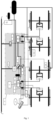
Fig. 1 is an overall system framework diagram of the railway wagon brake control system provided by the present invention; -
Fig. 2 is a structural diagram of one side of the railway wagon brake control system provided by the present invention; and -
Fig. 3 is a structural diagram of the other side of the railway wagon brake control system provided by the present invention. - The reference numerals are as follows:
1-MUD main valve plate, 2-speed synchronization control host, 3-output pressure measuring point of relay valve, 4-electromagnetic exhaust valve, 5-block valve, 6-distribution valve, 7-ECP control host, 8-vehicle monitor, 9-pressure relay, 10-relay valve, 11-speed sensor, 12-disc brake, 13-weighing valve, 14-ECP pre-control chamber, 15-control air cylinder, 16-auxiliary reservoir, 17-train pipe. - The embodiments of the application are described below and examples of the embodiments are shown in the drawings, in which the same or similar reference symbols always indicate same or similar modules, or modules with same or similar functions. The exemplary embodiment described by the following figures is to explain the invention, but not a limit of the invention, which is limited only by the scope of the appended claims.
- ECP pre-control chamber: the air in the ECP pre-control chamber is the pilot air source of the ECP control host and the control air source of the ECP control host. The ECP control host controls the exhaust of the train pipe by controlling the air pressure in the air cylinder. Its working principle has been recorded in detail in the publication number:
CN201911305491.X - Control air cylinder: the air in the control air cylinder is the control air source of the distribution valve.
- Distribution valve: its role is to control the air inflation and exhaust of the acting air cylinder according to the pressure change in the train pipe, and realize the braking, pressure maintaining or release of the locomotive through the reversing valve and the application valve.
- Train pipe: the air pipe used for braking of cross-country trains is a brake pipe, also called train pipe.
- Its role is to achieve the purposes of being high in braking synchronism, good in deceleration consistency, and being capable of effectively improving the safety and service efficiency of railway wagons.
- As shown in
Fig. 1 , the present invention provides a railway wagon brake control system, comprising atrain pipe 17 and a plurality ofdisc brakes 12 which are used for braking the wheels of a railway wagon, and the braking action is performed on each wheel through the action of thedisc brake 12, belonging to a conventional technical means on trains, which will not be repeated here. - The system also comprises an ECP control host 7 and a
distribution valve 6 communicated with thetrain pipe 17; ablock valve 5 is provided between thedistribution valve 6 and thetrain pipe 17, in order to cut off or connect thedistribution valve 6 and thetrain pipe 17; thedistribution valve 6 is communicated with a plurality of relay valves 10, each relay valve 10 corresponds to each bogie of the railway wagon, and eachdisc brake 12 of the same bogie is communicated with the relay valve 10 corresponding to the bogie. In the present embodiment, take two groups of wheels arranged on the same bogie as an example: the same bogie is provided with a relay valve 10, and the output end of the relay valve 10 is connected to twodisc brakes 12 through a separate pipeline to break down the air pressure at the output end of the relay valve 10; eachdisc brake 12 brakes each group of wheels of the bogie, thereby controlling the action consistency and stability of thedisc brakes 12. In practical applications, the use of relay valve 10 can ensure good decomposition of pressure air. - The system also comprises a
control air cylinder 15 and an auxiliary reservoir 16 which are communicated with thedistribution valve 6; each bogie is provided with at least oneweighing valve 13, and eachweighing valve 13 is respectively communicated with the auxiliary reservoir 16 and the relay valve 10; the auxiliary reservoir 16 provides air source for the operation of eachweighing valve 13, and the output of the relay valve 10 is adjusted adaptively according to the output data of theweighing valve 13. Theweighing valve 13 is used for sensing the weight, and the relay valve 10 adjusts its output according to the output data of theweighing valve 13 to control the output pressure. - The system further comprises an ECP pre-control
chamber 14. The ECP pre-controlchamber 14 is communicated with thetrain pipe 17, and the ECP control host 7 controls the air pressure change in the ECP pre-controlchamber 14 so as to enable pressure air in the train pipe 7 to be exhausted. The ECP pre-controlchamber 14, thetrain pipe 17 and the ECP control host 7 are communicated through a pipeline. In the present embodiment, the ECP control host 7 comprises the on-off solenoid valve disclosed in the prior art (CN201911305491.X CN201911305491.X ECP pre-control chamber 14 so as to enable pressure air in the train pipe to be exhausted will not be further described. When the pressure air in thetrain pipe 17 is exhausted, the air pressure in thetrain pipe 17 will drop, and then it will be induced by thedistribution valve 6 to perform subsequent braking action. - To further promote the braking consistency and deceleration control of each wheel, the system also comprises a speed synchronization control host 2, and the speed synchronization control host 2 is installed in the main control cabinet of the railway wagon. The speed synchronization control host 2 is connected to a plurality of speed sensors 11, and each speed sensor 11 measures the speed of each wheel of the railway wagon. In practical application, each speed sensor 11 is installed on the axle end of each wheel of the railway wagon, and each speed sensor 11 measures the speed of each wheel by means of gear speed measurement. When the railway wagon is running, each speed sensor 11 can transmit the speed data of each wheel to the speed synchronization control host 2 which analyzes and processes the speed data, and then output the corresponding control command.
- Each
disc brake 12 is communicated with the corresponding relay valve 10 through an independent pipeline to ensure that the air output by the relay valve 10 can be further broken down, in order to meet the air pressure requirements ofdifferent disc brakes 12, and each pipeline is provided with anelectromagnetic exhaust valve 4. In the present embodiment, there are fourelectromagnetic exhaust valves 4 in total, and every twoelectromagnetic exhaust valves 4 correspond to one relay valve 10. Eachelectromagnetic exhaust valve 4 is respectively connected to the speed synchronization control host 2, and the speed synchronization control host 2 transmits the control command to eachelectromagnetic exhaust valve 4, in order to further control the air pressure of eachdisc brake 12. In practical application, the speed synchronization control host 2 controls the speeds of the four groups of wheels of the vehicle by controlling the air pressure of eachdisc brake 12 during speed regulation, so as to achieve the speed synchronization of the wheels. Preferably, thetrain pipe 17 is communicated with the pressure relay. The circuit of the speed synchronization control host 2 is controlled by thepressure relay 9. Thepressure relay 9 is connected in series to the power circuit of the speed synchronization control host 2. Thepressure relay 9 makes corresponding actions according to the pressure changes in thetrain pipe 17. For example, when the pressure of thetrain pipe 17 is higher than the set value, thepressure relay 9 will act, in order to turn on the power circuit of the speed synchronization control host 2; the speed synchronization control host 2 is in the working state, and the speed synchronization control host 2 receives the speed data fed back by each speed sensor 11 to control the air volume of eachelectromagnetic exhaust valve 4. - In order to realize the arrangement of the air path of each component and the integration and summary of each component, as shown in
Fig. 2 andFig. 3 , the system also comprises an MUDmain valve plate 1, and the MUDmain valve plate 1 is 910*360*40mm aluminum alloy brazing sheet; the weighingvalve 13 anddistribution valve 6 are installed on one side of the MUDmain valve plate 1, and the ECP control host 7,ECP pre-control chamber 14,control air cylinder 15,block valve 5,pressure relay 9 and eachelectromagnetic exhaust valve 4 are installed on the other side, in order to finally realize integrated plate type structural design of the whole system. Thetrain pipe 17, thecontrol air cylinder 15, the output port of thedistribution valve 6, the output port of the relay valve 10 and the ECP pre-control air cylinder are connected respectively through the pipeline interface on the MUDmain valve plate 1. The specific pipeline layout can be adaptively designed according to the actual situation, and its pipeline connection relationship is as shown in the system framework diagram inFig. 1 . - The system also comprises a plurality of pressure sensors connected to the ECP control host 7, wherein each pressure sensor measures the pressure of the
train pipe 17, the pressure of thecontrol air cylinder 15, the output pressure of thedistribution valve 6 and the output pressure of the relay valve 10 (i.e., output pressure measuring point of the relay valve inFig. 1 ). During the operation of railway wagons, the ECP control host 7 continuously measures the pressure of thetrain pipe 17, the pressure ofcontrol air cylinder 15, the output pressure of thedistribution valve 6 and the output pressure of the relay valve 10 through the pressure sensor, and judges whether the vehicle is out of order according to the correspondence of each output pressure. However, the pneumatic brake fault monitored by the ECP control host 7 is transmitted to an external device through an RS485 communication line, so that the staff can repair in time. - The working principle of the railway wagon brake control system in the present embodiment is as follows:
After theblock valve 5 is opened and the speed synchronization control host 2 and ECP control host 7 are powered on, the whole brake system can work normally. - The whole railway wagon is provided with a plurality of ECP control hosts 7, and each ECP control host 7 has wireless communication function. All ECP control hosts 7 in the train are in the same local area network, and the control commands generated by the ECP control hosts 7 and the vehicle fault information monitored by the vehicle monitor 10 are wirelessly transmitted in the local area network.
- When the train is implementing the brake operation, the ECP control host 7 synchronously implements the air exhaust action in the
train pipe 17 through a wireless network, and thedistribution valve 6 senses the pressure drop in thetrain pipe 17, and then further controls the air in the auxiliary reservoir 16 to flow to thedisc brake 12 to complete the output air pressure control; - The relay valve 10 further breaks down and controls the output pressure according to the weight of the vehicle body fed back by the weighing
valve 13 and outputs it to thedisc brake 12 through the pipeline; - The speed sensor 11 at the axle end collects the wheel speed, and the speed synchronization control host 2 controls the
electromagnetic exhaust valve 4 according to the wheel speed data to further break down and control the output pressure to thedisc brake 12; - The output air pressure is controlled finally through the ECP control host 7 and the
distribution valve 6 to sense the pressure change of thetrain pipe 17, and therefore the purposes of being high in braking synchronism, good in deceleration consistency and capable of achieving real-time self-monitoring are achieved. - The present embodiment provides a railway wagon brake control method, which is applied in the railway wagon brake control system, and the control method comprises:
- (1) The
block valve 5 is opened and the speed synchronization control host 2 and ECP control host 7 are powered on, to ensure that the whole brake system is in the normal working state; - (2) The ECP control host 7 controls the air pressure change in the
ECP pre-control chamber 14 so as to enable pressure air in thetrain pipe 17 to be exhausted, thus reducing the pressure in thetrain pipe 17; - (3) After the pressure in the
train pipe 17 is reduced, the air in the auxiliary reservoir 16 is controlled by thedistribution valve 6 to flow to each relay valve 10. At this time, the air circuit between thetrain pipe 17 and thedistribution valve 6 is disconnected, and the pressure air for the subsequent braking of thedistribution valve 6 comes from the auxiliary reservoir 16; - (4) The relay valve 10 breaks down its output pressure to each
disc brake 12 according to the output of each weighingvalve 13, and the weighingvalve 13 senses the weight; the relay valve 10 adjusts its output according to the output data of the weighingvalve 13, and then breaks down the output pressure air and flows it to eachdisc brake 12; - (5) In order to further break down the pressure air output by the relay valve 10 and implement the deceleration control of the four wheel axles of the vehicle (only limited to the four wheels in the present embodiment), the control method is as follows:
- speed sensors 11 are configured on the axle ends of each wheel of the railway wagon, and the speed of each wheel is measured by the speed sensor 11 and fed back to the speed synchronization control host 2;
- an
electromagnetic exhaust valve 4 is provided on the connecting pipeline between the relay valve 10 and eachdisc brake 12; - the speed synchronization control host 2 controls the corresponding
electromagnetic exhaust valve 4 according to the speed data of each wheel, so as to control the output pressure to eachdisc brake 12, and achieve the deceleration control of the four axles of the vehicle; and
- (6) Each disc brake performs braking action.
- In the control method of the present embodiment, the ECP control host 7 continuously measures the pressure of the
train pipe 17, the pressure of thecontrol air cylinder 15, the output pressure of thedistribution valve 6 and the output pressure of the relay valve 10 through the pressure sensor, and judges whether the vehicle is out of order according to the correspondence of each output pressure. The monitored pneumatic brake fault is transmitted to an external device through an RS485 communication line, so that the staff can repair in time. - It should be noted that, in the description of the present application, the terms "first", "second", etc. are only used for description, but cannot be understood to indicate or imply relative importance. In addition, in the description of the present application, "multiple" means at least two, unless otherwise specified, unless otherwise specified.
- Any process or method description in the flow diagram or otherwise described herein can be understood to represent a module, segment or part of a code including one or more executable instructions for implementing the steps of a specific logic function or process, and the scope of the preferred implementation method of the present application includes other implementations, which may not be in the order shown or discussed. It should be understood by those skilled in the art of the embodiments of the present application that functions are performed in a substantially simultaneous manner or in a reverse order according to the functions involved.
- It should be understood that, all parts of the present application can be realized by hardware, software, firmware or combination thereof. In the above embodiments, multiple steps or methods may be implemented with software or firmware stored in a memory and executed by a suitable instruction execution system. For example, if it is implemented by hardware, as in another embodiment, it can be implemented by any one of the following technologies known in the art or their combination: a discrete logic circuit with a logic gate circuit for realizing a logic function on a data signal, an application-specific integrated circuit with a suitable combined logic gate circuit, a programmable gate array (PGA), field programmable gate array (FPGA), etc.
- Those skilled in the art can understand that all or part of the steps carried by the method of implementing the above embodiments can be completed by instructing relevant hardware through a program. The program can be stored in a computer-readable storage medium. When the program is executed, it includes one or a combination of the steps of the method embodiment.
- In addition, all functional units in each embodiment of the present application can be integrated in one processing module, or all units can also physically exist independently, or two or over units are integrated in one module. The module can be integrated in the form of hardware, and can also be integrated in the form of software function module. If the module is integrated in the form of software function module and used as an independent product for sale or use, it can also be stored in a computer-readable storage medium.
- The storage medium mentioned above can be read only memory, disk or optical disk, etc.
- In the Description, the reference terms "one embodiment", "some embodiments", "example", "specific example", or "some examples", etc. are described to refer to that the specific features, structures, materials or characteristics described in combination with the embodiment or example are included in at least one embodiment or example of the present application. In the description, illustrative expressions of the above terms do not necessarily refer to the same embodiment or example. Further, the specific features, structures, materials or characteristics described may be combined in any one or more embodiments or examples in a suitable manner, in accordance with the appended claims.
- Although the embodiments of the present application have been illustrated and described, it can be understood that the above embodiments are exemplary and should not be construed as limitations to the present application. Changes, modifications, replacements and variations within the scope of the present application can be made to these embodiments by those of ordinary skill in the art, in accordance with the appended claims.
Claims (10)
- A railway wagon brake control system, comprising a train pipe (17) and a plurality of disc brakes (12) which are used for braking the wheels of a railway wagon, the system further comprises an ECP control host (7) and a distribution valve (6) communicated with the train pipe (17); the distribution valve is communicated with a plurality of relay valves, each relay valve corresponds to each bogie of the rail wagon, and each disc brake (12) of the same bogie is communicated with the relay valve corresponding to the bogie;the system also comprises a control air cylinder (15) and an auxiliary reservoir (16) which are communicated with the distribution valve (6); each bogie is provided with at least one weighing valve (13), and each weighing valve (13) is respectively communicated with the auxiliary reservoir (16) and the relay valve;characterized in thatthe system further comprises an ECP pre-control chamber (14), the ECP pre-control chamber is communicated with the train pipe, and the ECP control host (7) controls the air pressure change in the ECP pre-control chamber (14) so as to enable pressure air in the train pipe to be exhausted;the system further comprises a speed synchronization control host (2), wherein the speed synchronization control host is connected to a plurality of speed sensors (11), and each speed sensor measures the speed of each wheel of the railway wagon.
- The railway wagon brake control system according to claim 1, characterized in that, the speed sensors (11) are installed on the axle ends of each wheel of the railway wagon.
- The railway wagon brake control system according to claim 1, characterized in that, the disc brake (12) is communicated with the corresponding relay valve through an independent pipeline, and each pipeline is provided with an electromagnetic exhaust valve (4), which is respectively connected to the speed synchronization control host (2).
- The railway wagon brake control system according to claim 3, characterized in that, the train pipe (17) is communicated with a pressure relay (10), which controls the circuit of each electromagnetic exhaust valve (4).
- The railway wagon brake control system according to claim 4, characterized by also comprising an MUD main valve plate (1), wherein the relay valve and distribution valve (6) are installed on one side of the MUD main valve plate (1), and the ECP control host (7), ECP pre-control chamber (14), control air cylinder (15), pressure relay (10) and each electromagnetic exhaust valve (4) are installed on the other side.
- The railway wagon brake control system according to claim 1, characterized in that, a block valve (5) is provided between the distribution valve (6) and the train pipe (17).
- The railway wagon brake control system according to claim 1, characterized by also comprising a plurality of pressure sensors connected to the ECP control host (7), wherein each pressure sensor measures the pressure of the train pipe (17), the pressure of the control air cylinder (15), the output pressure of the distribution valve (6) and the output pressure of the relay valve.
- The railway wagon brake control system according to claim 1, characterized in that, the ECP control host (7) is transmitted to an external device through an RS485 communication line, and the speed synchronization control host (2) is installed in the main control cabinet of the railway wagon.
- A railway wagon brake control method, characterized in that, the method is applied in the railway wagon brake control system according to any of claims 1-8, and the method comprises:the ECP control host (7) controls the air pressure change in the ECP pre-control chamber (14) so as to enable pressure air in the train pipe (17) to be exhausted;after the pressure in the train pipe is reduced, the air in the auxiliary reservoir (16) is controlled to flow to each relay valve through the distribution valve (6);each relay valve breaks down its output pressure to each disc brake (12) according to the output of each weighing valve (13); andeach disc brake performs braking action;the method further comprises:speed sensors (11) are configured on the axle ends of each wheel of the railway wagon, and the speed of each wheel is measured by the speed sensor and fed back to the speed synchronization control host (2);an electromagnetic exhaust valve (4) is provided on the connecting pipeline between the relay valve and each disc brake (12); andthe speed synchronization control host controls the corresponding electromagnetic exhaust valve (4) according to the speed data of each wheel, so as to control the output pressure to each disc brake.
- The railway wagon brake control method according to claim 9, characterized in that, the ECP control host (7) continuously measures the pressure of the train pipe (17), the pressure of the control air cylinder (15), the output pressure of the distribution valve (6) and the output pressure of the relay valve through the pressure sensor, and determines whether the vehicle is out of order according to the correspondence of each output pressure.
Applications Claiming Priority (1)
| Application Number | Priority Date | Filing Date | Title |
|---|---|---|---|
| PCT/CN2020/105138 WO2022021055A1 (en) | 2020-07-28 | 2020-07-28 | Railway wagon brake control system and control method |
Publications (3)
| Publication Number | Publication Date |
|---|---|
| EP4186757A1 EP4186757A1 (en) | 2023-05-31 |
| EP4186757A4 EP4186757A4 (en) | 2023-09-27 |
| EP4186757B1 true EP4186757B1 (en) | 2025-06-04 |
Family
ID=80037951
Family Applications (1)
| Application Number | Title | Priority Date | Filing Date |
|---|---|---|---|
| EP20946610.1A Active EP4186757B1 (en) | 2020-07-28 | 2020-07-28 | Railway wagon brake control system and control method |
Country Status (3)
| Country | Link |
|---|---|
| EP (1) | EP4186757B1 (en) |
| AU (1) | AU2020460690B2 (en) |
| WO (1) | WO2022021055A1 (en) |
Families Citing this family (3)
| Publication number | Priority date | Publication date | Assignee | Title |
|---|---|---|---|---|
| CN112781897A (en) * | 2020-12-23 | 2021-05-11 | 神华铁路装备有限责任公司 | Installation tool and train test system |
| CN115923856A (en) * | 2022-11-30 | 2023-04-07 | 宝鸡中车时代工程机械有限公司 | Catenary insulator washing vehicle |
| CN116279374A (en) * | 2023-04-07 | 2023-06-23 | 西南交通大学希望学院 | Train brake pipeline maintenance system |
Family Cites Families (9)
| Publication number | Priority date | Publication date | Assignee | Title |
|---|---|---|---|---|
| AU2003302618A1 (en) * | 2002-11-29 | 2004-06-23 | Tecnologie Diesel E Sistemi Frenanti S.P.A. | Hydraulically-actuated parking brake with mechanical blocking means |
| WO2006122374A1 (en) * | 2005-05-20 | 2006-11-23 | Queensland Rail | Electronically controlled pneumatic brake system |
| CN202017720U (en) * | 2011-03-02 | 2011-10-26 | 中国铁道科学研究院机车车辆研究所 | Disc braking device used for railway truck |
| CN102152800B (en) * | 2011-03-02 | 2013-06-05 | 中国铁道科学研究院机车车辆研究所 | Wagon brake system |
| EP2952405B1 (en) * | 2013-01-30 | 2021-10-06 | Nabtesco Corporation | Railroad vehicle brake device, railroad vehicle, and railroad vehicle formation |
| DE102014113056A1 (en) * | 2014-09-10 | 2016-03-10 | Knorr-Bremse Systeme für Nutzfahrzeuge GmbH | disc brake system |
| CN110949350B (en) * | 2019-12-18 | 2024-10-08 | 眉山中车制动科技股份有限公司 | Control device for electric pneumatic braking and braking control system |
| CN111422217B (en) * | 2020-04-29 | 2023-08-29 | 吕振国 | Method for recovering adhesive force of disc brake locomotive |
| CN111873970B (en) * | 2020-07-28 | 2024-08-27 | 眉山中车制动科技股份有限公司 | Railway wagon brake control system and control method |
-
2020
- 2020-07-28 WO PCT/CN2020/105138 patent/WO2022021055A1/en not_active Ceased
- 2020-07-28 EP EP20946610.1A patent/EP4186757B1/en active Active
- 2020-07-28 AU AU2020460690A patent/AU2020460690B2/en active Active
Also Published As
| Publication number | Publication date |
|---|---|
| EP4186757A1 (en) | 2023-05-31 |
| WO2022021055A1 (en) | 2022-02-03 |
| AU2020460690B2 (en) | 2025-01-30 |
| AU2020460690A1 (en) | 2023-03-16 |
| EP4186757A4 (en) | 2023-09-27 |
Similar Documents
| Publication | Publication Date | Title |
|---|---|---|
| AU2020460690B2 (en) | Railway wagon brake control system and control method | |
| CN111873970B (en) | Railway wagon brake control system and control method | |
| US8190311B2 (en) | Adaptive brake scheme during a locomotive distributed power communication loss | |
| CN109572654B (en) | Impact rate control method based on traction braking fusion control system | |
| AU762654B2 (en) | Railway emulation brake | |
| CN101941382B (en) | Electro-pneumatic braking system and method for railway freight cars based on wireless communication | |
| CN110194135B (en) | Hinged rubber-wheel trolley bus braking system suitable for 3-5 sections of carriages | |
| CN101508287B (en) | Electropneumatic braking method and system with fault complementary control based on single-axis control | |
| JP2002528329A (en) | Brake system for railway vehicles | |
| CN114572270B (en) | Axle control type brake control system and rail transit vehicle | |
| CN107298111A (en) | A kind of empty electrical brake system for goods train | |
| AU2012380356A1 (en) | Train control system | |
| CN105774785A (en) | Railway vehicle air brake system | |
| AU2002353994B2 (en) | Locomotive brake pipe valve cut-out failure detection and correction | |
| CN113120024A (en) | Pure air emergency braking control method and control device for railway vehicle braking system | |
| CN110949350A (en) | Control device for electro-pneumatic braking and braking control system | |
| EP4011728B1 (en) | Brake control system for a rail car | |
| CN212243320U (en) | Railway wagon brake control system | |
| CN108944879A (en) | A kind of braking method, brake apparatus and railway freight-car | |
| CN106043257B (en) | A kind of interior frame control formula braking system and its brake control method for implementing braking force distribution of unit | |
| WO2026031344A1 (en) | Rail transit vehicle brake control system and control method thereof, and rail transit vehicle | |
| CN216359959U (en) | Half-power rail vehicle moving shaft braking interlocking control device | |
| JP2025506949A (en) | Brake system for rail vehicles and method for driving and controlling such a brake system - Patents.com | |
| CN113928291A (en) | Half-power rail vehicle moving shaft brake interlocking control device and control method | |
| JPH1044964A (en) | Brake device for rolling stock |
Legal Events
| Date | Code | Title | Description |
|---|---|---|---|
| STAA | Information on the status of an ep patent application or granted ep patent |
Free format text: STATUS: THE INTERNATIONAL PUBLICATION HAS BEEN MADE |
|
| PUAI | Public reference made under article 153(3) epc to a published international application that has entered the european phase |
Free format text: ORIGINAL CODE: 0009012 |
|
| STAA | Information on the status of an ep patent application or granted ep patent |
Free format text: STATUS: REQUEST FOR EXAMINATION WAS MADE |
|
| 17P | Request for examination filed |
Effective date: 20230223 |
|
| AK | Designated contracting states |
Kind code of ref document: A1 Designated state(s): AL AT BE BG CH CY CZ DE DK EE ES FI FR GB GR HR HU IE IS IT LI LT LU LV MC MK MT NL NO PL PT RO RS SE SI SK SM TR |
|
| STAA | Information on the status of an ep patent application or granted ep patent |
Free format text: STATUS: EXAMINATION IS IN PROGRESS |
|
| A4 | Supplementary search report drawn up and despatched |
Effective date: 20230824 |
|
| RIC1 | Information provided on ipc code assigned before grant |
Ipc: B61H 13/00 20060101ALI20230818BHEP Ipc: B60T 17/22 20060101ALI20230818BHEP Ipc: B60T 13/66 20060101ALI20230818BHEP Ipc: B60T 8/18 20060101ALI20230818BHEP Ipc: B60T 8/58 20060101AFI20230818BHEP |
|
| 17Q | First examination report despatched |
Effective date: 20230905 |
|
| DAV | Request for validation of the european patent (deleted) | ||
| DAX | Request for extension of the european patent (deleted) | ||
| GRAP | Despatch of communication of intention to grant a patent |
Free format text: ORIGINAL CODE: EPIDOSNIGR1 |
|
| STAA | Information on the status of an ep patent application or granted ep patent |
Free format text: STATUS: GRANT OF PATENT IS INTENDED |
|
| RIC1 | Information provided on ipc code assigned before grant |
Ipc: B61H 13/00 20060101ALI20250128BHEP Ipc: B60T 17/22 20060101ALI20250128BHEP Ipc: B60T 13/66 20060101ALI20250128BHEP Ipc: B60T 8/18 20060101ALI20250128BHEP Ipc: B60T 8/58 20060101AFI20250128BHEP |
|
| INTG | Intention to grant announced |
Effective date: 20250214 |
|
| GRAS | Grant fee paid |
Free format text: ORIGINAL CODE: EPIDOSNIGR3 |
|
| GRAA | (expected) grant |
Free format text: ORIGINAL CODE: 0009210 |
|
| STAA | Information on the status of an ep patent application or granted ep patent |
Free format text: STATUS: THE PATENT HAS BEEN GRANTED |
|
| AK | Designated contracting states |
Kind code of ref document: B1 Designated state(s): AL AT BE BG CH CY CZ DE DK EE ES FI FR GB GR HR HU IE IS IT LI LT LU LV MC MK MT NL NO PL PT RO RS SE SI SK SM TR |
|
| REG | Reference to a national code |
Ref country code: GB Ref legal event code: FG4D |
|
| REG | Reference to a national code |
Ref country code: CH Ref legal event code: EP |
|
| REG | Reference to a national code |
Ref country code: DE Ref legal event code: R096 Ref document number: 602020052497 Country of ref document: DE |
|
| REG | Reference to a national code |
Ref country code: IE Ref legal event code: FG4D |
|
| REG | Reference to a national code |
Ref country code: NL Ref legal event code: MP Effective date: 20250604 |
|
| PG25 | Lapsed in a contracting state [announced via postgrant information from national office to epo] |
Ref country code: FI Free format text: LAPSE BECAUSE OF FAILURE TO SUBMIT A TRANSLATION OF THE DESCRIPTION OR TO PAY THE FEE WITHIN THE PRESCRIBED TIME-LIMIT Effective date: 20250604 Ref country code: ES Free format text: LAPSE BECAUSE OF FAILURE TO SUBMIT A TRANSLATION OF THE DESCRIPTION OR TO PAY THE FEE WITHIN THE PRESCRIBED TIME-LIMIT Effective date: 20250604 |
|
| PGFP | Annual fee paid to national office [announced via postgrant information from national office to epo] |
Ref country code: DE Payment date: 20250728 Year of fee payment: 6 |
|
| REG | Reference to a national code |
Ref country code: LT Ref legal event code: MG9D |
|
| PG25 | Lapsed in a contracting state [announced via postgrant information from national office to epo] |
Ref country code: GR Free format text: LAPSE BECAUSE OF FAILURE TO SUBMIT A TRANSLATION OF THE DESCRIPTION OR TO PAY THE FEE WITHIN THE PRESCRIBED TIME-LIMIT Effective date: 20250905 Ref country code: NO Free format text: LAPSE BECAUSE OF FAILURE TO SUBMIT A TRANSLATION OF THE DESCRIPTION OR TO PAY THE FEE WITHIN THE PRESCRIBED TIME-LIMIT Effective date: 20250904 |
|
| PG25 | Lapsed in a contracting state [announced via postgrant information from national office to epo] |
Ref country code: PL Free format text: LAPSE BECAUSE OF FAILURE TO SUBMIT A TRANSLATION OF THE DESCRIPTION OR TO PAY THE FEE WITHIN THE PRESCRIBED TIME-LIMIT Effective date: 20250604 |
|
| PG25 | Lapsed in a contracting state [announced via postgrant information from national office to epo] |
Ref country code: BG Free format text: LAPSE BECAUSE OF FAILURE TO SUBMIT A TRANSLATION OF THE DESCRIPTION OR TO PAY THE FEE WITHIN THE PRESCRIBED TIME-LIMIT Effective date: 20250604 |
|
| PG25 | Lapsed in a contracting state [announced via postgrant information from national office to epo] |
Ref country code: HR Free format text: LAPSE BECAUSE OF FAILURE TO SUBMIT A TRANSLATION OF THE DESCRIPTION OR TO PAY THE FEE WITHIN THE PRESCRIBED TIME-LIMIT Effective date: 20250604 |
|
| PG25 | Lapsed in a contracting state [announced via postgrant information from national office to epo] |
Ref country code: RS Free format text: LAPSE BECAUSE OF FAILURE TO SUBMIT A TRANSLATION OF THE DESCRIPTION OR TO PAY THE FEE WITHIN THE PRESCRIBED TIME-LIMIT Effective date: 20250904 |
|
| PG25 | Lapsed in a contracting state [announced via postgrant information from national office to epo] |
Ref country code: LV Free format text: LAPSE BECAUSE OF FAILURE TO SUBMIT A TRANSLATION OF THE DESCRIPTION OR TO PAY THE FEE WITHIN THE PRESCRIBED TIME-LIMIT Effective date: 20250604 |
|
| PG25 | Lapsed in a contracting state [announced via postgrant information from national office to epo] |
Ref country code: NL Free format text: LAPSE BECAUSE OF FAILURE TO SUBMIT A TRANSLATION OF THE DESCRIPTION OR TO PAY THE FEE WITHIN THE PRESCRIBED TIME-LIMIT Effective date: 20250604 |
|
| PG25 | Lapsed in a contracting state [announced via postgrant information from national office to epo] |
Ref country code: PT Free format text: LAPSE BECAUSE OF FAILURE TO SUBMIT A TRANSLATION OF THE DESCRIPTION OR TO PAY THE FEE WITHIN THE PRESCRIBED TIME-LIMIT Effective date: 20251006 |
|
| REG | Reference to a national code |
Ref country code: AT Ref legal event code: MK05 Ref document number: 1800072 Country of ref document: AT Kind code of ref document: T Effective date: 20250604 |
|
| PG25 | Lapsed in a contracting state [announced via postgrant information from national office to epo] |
Ref country code: IS Free format text: LAPSE BECAUSE OF FAILURE TO SUBMIT A TRANSLATION OF THE DESCRIPTION OR TO PAY THE FEE WITHIN THE PRESCRIBED TIME-LIMIT Effective date: 20251004 |
|
| PG25 | Lapsed in a contracting state [announced via postgrant information from national office to epo] |
Ref country code: SM Free format text: LAPSE BECAUSE OF FAILURE TO SUBMIT A TRANSLATION OF THE DESCRIPTION OR TO PAY THE FEE WITHIN THE PRESCRIBED TIME-LIMIT Effective date: 20250604 Ref country code: AT Free format text: LAPSE BECAUSE OF FAILURE TO SUBMIT A TRANSLATION OF THE DESCRIPTION OR TO PAY THE FEE WITHIN THE PRESCRIBED TIME-LIMIT Effective date: 20250604 |
|
| PG25 | Lapsed in a contracting state [announced via postgrant information from national office to epo] |
Ref country code: CZ Free format text: LAPSE BECAUSE OF FAILURE TO SUBMIT A TRANSLATION OF THE DESCRIPTION OR TO PAY THE FEE WITHIN THE PRESCRIBED TIME-LIMIT Effective date: 20250604 |
|
| PG25 | Lapsed in a contracting state [announced via postgrant information from national office to epo] |
Ref country code: EE Free format text: LAPSE BECAUSE OF FAILURE TO SUBMIT A TRANSLATION OF THE DESCRIPTION OR TO PAY THE FEE WITHIN THE PRESCRIBED TIME-LIMIT Effective date: 20250604 |
|
| PG25 | Lapsed in a contracting state [announced via postgrant information from national office to epo] |
Ref country code: SK Free format text: LAPSE BECAUSE OF FAILURE TO SUBMIT A TRANSLATION OF THE DESCRIPTION OR TO PAY THE FEE WITHIN THE PRESCRIBED TIME-LIMIT Effective date: 20250604 |
|
| PG25 | Lapsed in a contracting state [announced via postgrant information from national office to epo] |
Ref country code: IT Free format text: LAPSE BECAUSE OF FAILURE TO SUBMIT A TRANSLATION OF THE DESCRIPTION OR TO PAY THE FEE WITHIN THE PRESCRIBED TIME-LIMIT Effective date: 20250604 |
|
| REG | Reference to a national code |
Ref country code: CH Ref legal event code: H13 Free format text: ST27 STATUS EVENT CODE: U-0-0-H10-H13 (AS PROVIDED BY THE NATIONAL OFFICE) Effective date: 20260224 |
|
| REG | Reference to a national code |
Ref country code: DE Ref legal event code: R097 Ref document number: 602020052497 Country of ref document: DE |
|
| PG25 | Lapsed in a contracting state [announced via postgrant information from national office to epo] |
Ref country code: RO Free format text: LAPSE BECAUSE OF FAILURE TO SUBMIT A TRANSLATION OF THE DESCRIPTION OR TO PAY THE FEE WITHIN THE PRESCRIBED TIME-LIMIT Effective date: 20250604 |
|
| PG25 | Lapsed in a contracting state [announced via postgrant information from national office to epo] |
Ref country code: LU Free format text: LAPSE BECAUSE OF NON-PAYMENT OF DUE FEES Effective date: 20250728 |
|
| REG | Reference to a national code |
Ref country code: BE Ref legal event code: MM Effective date: 20250731 |
|
| PG25 | Lapsed in a contracting state [announced via postgrant information from national office to epo] |
Ref country code: MC Free format text: LAPSE BECAUSE OF FAILURE TO SUBMIT A TRANSLATION OF THE DESCRIPTION OR TO PAY THE FEE WITHIN THE PRESCRIBED TIME-LIMIT Effective date: 20250604 |
|
| PLBE | No opposition filed within time limit |
Free format text: ORIGINAL CODE: 0009261 |
|
| STAA | Information on the status of an ep patent application or granted ep patent |
Free format text: STATUS: NO OPPOSITION FILED WITHIN TIME LIMIT |
|
| PG25 | Lapsed in a contracting state [announced via postgrant information from national office to epo] |
Ref country code: DK Free format text: LAPSE BECAUSE OF FAILURE TO SUBMIT A TRANSLATION OF THE DESCRIPTION OR TO PAY THE FEE WITHIN THE PRESCRIBED TIME-LIMIT Effective date: 20250604 |
|
| PG25 | Lapsed in a contracting state [announced via postgrant information from national office to epo] |
Ref country code: BE Free format text: LAPSE BECAUSE OF NON-PAYMENT OF DUE FEES Effective date: 20250731 |
|
| REG | Reference to a national code |
Ref country code: CH Ref legal event code: L10 Free format text: ST27 STATUS EVENT CODE: U-0-0-L10-L00 (AS PROVIDED BY THE NATIONAL OFFICE) Effective date: 20260416 |
|
| PG25 | Lapsed in a contracting state [announced via postgrant information from national office to epo] |
Ref country code: CH Free format text: LAPSE BECAUSE OF NON-PAYMENT OF DUE FEES Effective date: 20250731 |
|
| 26N | No opposition filed |
Effective date: 20260305 |