EP4186649A1 - Method of objective mtp latency measurement in a tele-operation with remote vision-through mr - Google Patents
Method of objective mtp latency measurement in a tele-operation with remote vision-through mr Download PDFInfo
- Publication number
- EP4186649A1 EP4186649A1 EP21210443.4A EP21210443A EP4186649A1 EP 4186649 A1 EP4186649 A1 EP 4186649A1 EP 21210443 A EP21210443 A EP 21210443A EP 4186649 A1 EP4186649 A1 EP 4186649A1
- Authority
- EP
- European Patent Office
- Prior art keywords
- teleoperation
- motion
- time information
- image data
- client
- Prior art date
- Legal status (The legal status is an assumption and is not a legal conclusion. Google has not performed a legal analysis and makes no representation as to the accuracy of the status listed.)
- Granted
Links
Images


Classifications
-
- B—PERFORMING OPERATIONS; TRANSPORTING
- B25—HAND TOOLS; PORTABLE POWER-DRIVEN TOOLS; MANIPULATORS
- B25J—MANIPULATORS; CHAMBERS PROVIDED WITH MANIPULATION DEVICES
- B25J9/00—Program-controlled manipulators
- B25J9/16—Program controls
- B25J9/1679—Program controls characterised by the tasks executed
- B25J9/1689—Teleoperation
-
- G—PHYSICS
- G05—CONTROLLING; REGULATING
- G05B—CONTROL OR REGULATING SYSTEMS IN GENERAL; FUNCTIONAL ELEMENTS OF SUCH SYSTEMS; MONITORING OR TESTING ARRANGEMENTS FOR SUCH SYSTEMS OR ELEMENTS
- G05B2219/00—Program-control systems
- G05B2219/30—Nc systems
- G05B2219/40—Robotics, robotics mapping to robotics vision
- G05B2219/40131—Virtual reality control, programming of manipulator
-
- G—PHYSICS
- G05—CONTROLLING; REGULATING
- G05B—CONTROL OR REGULATING SYSTEMS IN GENERAL; FUNCTIONAL ELEMENTS OF SUCH SYSTEMS; MONITORING OR TESTING ARRANGEMENTS FOR SUCH SYSTEMS OR ELEMENTS
- G05B2219/00—Program-control systems
- G05B2219/30—Nc systems
- G05B2219/40—Robotics, robotics mapping to robotics vision
- G05B2219/40151—Time delay, problems caused by time delay between local and remote
Definitions
- the present invention relates to a method, means, a teleoperation client and a teleoperation object for objectively measuring and monitoring a motion-to-photon (MTP) latency in a teleoperation system with a remote vision-through mixed reality (MR).
- MTP motion-to-photon
- MR remote vision-through mixed reality
- An MTP latency is an end-to-end latency that is accumulated from the latency of each of transactions in a teleoperation system with a remote vision-through MR.
- An MTP latency is one of the main factors that bring a direct impact on a Quality of Experience (QoE) while the system is in operation.
- QoE Quality of Experience
- such a teleoperation system with a remote vision-through MR consists of multiple transactions and processes, for instance, including motion-sensing and tracking, mobile camera sensing, physical movement of an object, video encoding, video decoding, network transmission, local asynchronous warping, and so on.
- Each of these multiple transactions shall cause transaction latencies that are accumulated to increase an end-to-end MTP latency.
- a teleoperation system with a remote vision-through MR is getting more attention since a demand from the industry has increased in many domains such as tele-driving of automotive, teleoperation of industrial robots and teleoperation of drones. Furthermore, the advent of 5G mobile networks with many innovative technologies, such as network slicing technology and adaptively managed latency, can intensify an improved mobility of remotely located objects in terms of a wider coverage and shorter latency. In every teleoperation system with a remote vision-through MR, the MTP latency is a very critical QoE parameter which affects the service quality directly.
- the MTP latency is not short enough while the system is in operation, then an MR user cannot operate remotely located objects conveniently since all the refreshed screens shown on the MR display panel will be displayed with longer lags between the MR user's head, body, arm or hand motions and remotely located object's corresponding movement.
- the measurement of an MTP latency is a very complicated task since such an MTP latency is a summation of series of partial latencies caused in each of separated transactions and separated hardware devices. Furthermore, those partial latencies are accumulated through multiple network connectivity.
- the MTP latency measurement was conducted in a labor-centric way, i.e., by taking pictures of the MR user's motions and those of the remotely located object's corresponding movement with high-speed cameras and comparing them to count an MTP latency in millisecond(s).
- This measurement method based on a high-speed camera has several problems and restrictions. Firstly, it cannot measure the MTP latency precisely since it is highly dependent on a human's perception. Secondly, it cannot provide a systematic measurement in a real-time basis so that it can support neither real-time-based monitoring nor log data accumulation.
- a method for measuring a motion-to-photon, MTP, latency in a teleoperation system comprising: obtaining motion tracking data for a motion of a first object at a teleoperation client, assigning first time information to the motion tracking data, transmitting the motion tracking data and the first time information from the teleoperation client to a teleoperation object, controlling a motion of a second object using the motion tracking data at the teleoperation object, obtaining image data for the motion of the second object based on the motion tracking data at the teleoperation object, obtaining second time information associated with the image data, and measuring an MTP latency based on the first time information and the second time information.
- an MTP latency may be objectively measured by managing time information in end-to-end transactions.
- the method may provide an MTP latency which starts from the moment of a first object's motion (e.g. an MR user's motion) and ends by the moment of an image frame refresh on a display panel at a teleoperation client by using the first time information assigned at the moment of the first object's motion while obtaining the motion tracking data and the second time information obtained at the moment of the refresh of the image frame for the motion of the second object controlled based on the motion tracking data of the first object's motion.
- an MTP latency may be measured on a real-time basis which enables the data to be continuously generated and fed into a QoE management means for further data accumulation and data mining analysis.
- the first time information may indicate the time at which the motion tracking data for a motion of a first object is obtained at the teleoperation client and/or the time at which the motion tracking data for a motion of a first object is transmitted from the teleoperation client to the teleoperation object.
- the first time information can be assigned in a simple manner, e.g. by using a time stamp when the corresponding action is occurred.
- an estimated time offset may be used alternatively or in addition, if a partial latency which cannot be measured by using a time stamp needs be taken into account in the MTP latency measurement.
- the method for measuring a motion-to-photon, MTP, latency further comprises: encoding the image data at the teleoperation object, transmitting the encoded image data from the teleoperation object to the teleoperation client, decoding the image data at the teleoperation client and sending the image data to a display controller at the teleoperation client and/or at the teleoperation object.
- the second time information may indicate the time at which the image data for the motion of the second object is generated at the teleoperation object and/or the time at which the image data for the motion of the second object is transmitted from the teleoperation object to the teleoperation client and/or the time at which the image data is sent to a/the display controller at the teleoperation client.
- the second time information is associated with an action, the second time information can be assigned in a simple manner, e.g. by using a time stamp when the corresponding action is occurred. Further, an estimated time offset may be used alternatively or in addition, if a partial latency which cannot be measured by using a time stamp needs be taken into account in the MTP latency measurement.
- the measuring an MTP latency may comprise retrieving the first time information and the second time information and calculating a difference between the first time information and the second time information.
- the measuring an MTP latency is carried out at the teleoperation client and/or at the teleoperation object and/or at a monitoring point.
- the MTP latency measured can be fed to a centralized QoE management system at the teleoperation client and/or at the teleoperation object and/or at a monitoring point for further analysis including data accumulation and data mining analysis.
- the motion of a first object comprises at least one of: an orientation change of the first object, a pose change of the first object and a movement of the first object, wherein the first object comprises a human body or a part of a human body such as a head, a body, an arm, a hand or a combination thereof.
- an orientation and pose tracking sensor may preferably be used to detect the motion.
- the orientation and pose tracking sensor may be mounted on an MR Head Mounted Device, HMD, glass device at the teleoperation client.
- a pose tracking sensor may preferably be used to detect the motion.
- the pose tracking sensor may be mounted on an MR controller at the teleoperation client.
- an MTP latency may be measured across multiple hardware devices such as an MR HMD glass, an MR controller and remotely located objects.
- the multiple hardware devices may operate in various network environments such as 5G mobile networks.
- the second object comprises a robot body or a part of a robot body such as a robot head, a robot body, a robot arm, a hand or a combination thereof.
- means for measuring a motion-to-photon, MTP, latency in a teleoperation system is provided for measuring the MTP latency according to the method of any of preceding aspects.
- a teleoperation client for measuring a motion-to-photon, MTP, latency in a teleoperation system, comprising: a processor configured to obtain motion tracking data for a motion of a first object and to assign first time information to the motion tracking data, a transmitter configured to transmit the motion tracking data and the first time information to a teleoperation object, and a receiver configured to receive image data from the teleoperation object, wherein the processor is further configured to: obtain second time information associated with the received image data and measure an MTP latency based on the first time information and the second time information.
- the teleoperation client further comprises one or more sensors for sensing a motion of a first object, and a display controller.
- the teleoperation client further comprises a Mixed Reality, MR, controller, the MR controller comprising a/the sensor for sensing an orientation change and/or a pose change, and/or a Mixed Reality, MR, Head Mounted Display, HMD, glass device, the MR HMD glass device comprising the processor and/or a/the sensor for sensing an orientation change and/or a pose change.
- a teleoperation object for measuring a motion-to-photon, MTP, latency in a teleoperation system, comprising: a receiver configured to receive motion tracking data and first time information from the teleoperation client, a processor configured to control a motion of a second object using the motion tracking data, a sensing device configured to obtain image data for the motion of the second object based on the motion tracking data, the processor and/or the sensing device being configured to obtain second time information associated with the image data, and a transmitter configured to transmit the image data and the second time information.
- the sensing device may be a mobile camera.
- the processor is further configured to measure the MTP latency based on the first time information and the second time information.
- the second object comprises a robot or a part of a robot such as a robot head, a robot body, a robot arm and/or a robot hand.
- Fig. 1 shows an overview of a teleoperation system in which the method for measuring an MTP latency according to an embodiment of the invention can be applied.
- a teleoperation system comprises a teleoperation client and a teleoperation object.
- the teleoperation client may comprise a first motion tracking sensor 7, a processor 9 and a display controller 11.
- the first motion tracking sensor 7 may be mounted on an MR HMD glass device 1 for sensing a motion of an MR user (a first object).
- the first motion tracking sensor 7 may comprise a 3 up to 6 Degrees of Freedom (DoF) sensor(s) which may be an orientation and/or tracking sensor for sensing a head and/or body movement of the MR user.
- DoF Degrees of Freedom
- the processor 9 and the display controller 11 are configured in the MR HMD glass device. In another embodiment, however, the processor 9 and the display controller 11 may be configured in a separate device such as a 5G smartphone.
- the processor 9 preferably configured in an MR HMD glass device 1 may be connected to an MR controller 5 via a communication network such as Bluetooth.
- a second motion tracking sensor 13 may be mounted for sensing a movement of the MR user.
- the MR controller may be held by hand or attached on an arm of the MR user.
- the second motion tracking sensor 13 mounted on the MR controller 5 may comprise a 3 up to 6 Degrees of Freedom (DoF) sensor which is an orientation and/or pose tracking sensor for sensing an arm and/or hand movement of the MR user.
- DoF Degrees of Freedom
- the first and/or the second motion tracking sensor 7, 13 may generate motion tracking data representing the motion of the MR user.
- the motion tracking data generated by the motion tracking sensor 13 of the MR controller 5 may be transmitted to the processor 9 of the MR HMD glass device 1 via the communication network such as Bluetooth.
- Time information associated with motion tracking data is assigned to the motion tracking data representing the motion of the MR user sensed by the motion tracking sensor(s) 7, 13. If the first time information indicates the time at which the motion tracking data is obtained at the teleoperation client, the first time information may be assigned by the motion tracking sensor(s) 7, 13 by using a time stamp when the motion of the first object is sensed. Alternatively or additionally, the first time information may be assigned by the processor 9 by using a time stamp at the time of reception of the motion tracking data obtained by the motion tracking sensor(s) 7, 13 are received at the processor. If the first time information indicates the time at which the motion tracking data is transmitted from the teleoperation client to the teleoperation object, the first time information may be assigned by the processor 9 by using a time stamp at the time of transmission.
- time information is assigned to the pose and/or orientation tracking data as first time information associated with the movement.
- the time information assignment may be carried out by a teleoperation client software running in an MR HDM glass or 5G smartphone in a 5G smartphone-tethered MR model. Further, the motion tracking data along with the time information may be stored at the teleoperation client.
- the motion tracking data along with time information is transferred from the teleoperation client to a teleoperation object for controlling the motion of a second object at the teleoperation object.
- the teleoperation object comprises a remotely-located robot 3
- the second object may be a robot head and/or body 15 and/or robot arm(s) and/or hand(s) 19.
- the teleoperation object further comprises a mobile camera 19 which may be equipped with the robot 3.
- a processor at the teleoperation object controls the motion of the second object based on the received motion tracking data representing the motion of the first objects.
- the teleoperation object comprises robot arms and hands 17, they may be manipulated as synchronized with the MR user's arm and hand motion.
- the mobile camera 19 senses the motion of the second object by capturing RGB signals and generates image frames as, e.g. video data, while the motion tracking data is kept synchronized with each image frame. That is, obtaining image data for the motion of the second object is carried out based on the received motion tracking data by synchronization of the controlling the motion of the second object and the obtaining the image data.
- Each image frame generated by the mobile camera 19 may be compressed by a video encoder of the processor at the teleoperation object and transmitted to the teleoperation client via a communication network, e.g. a 5G network.
- the processor 9 at the teleoperation client may decode the encoded video data received.
- the video data decoded may comprise the image frames synchronized with the motion tracking data and the first time information.
- the processor 9 at the teleoperation client may push the video data to the display controller 11 to be displayed at a display panel preferably configured in the MR glass device 1.
- the processor 9 may measure the MTP latency by retrieving and comparing the time difference between the first time information, e.g. a timestamp information included in the motion tracking data, and the current time at the time of transmission of the video data to the display controller.
- a (further) partial latency such as a latency incurred from transmission of the video data to display of the video data on the display panel may be estimated and added as an offset.
- motion tracking data obtained at the teleoperation client is kept and managed together with the time information through the end-to-end transaction across the network environment and the remotely operated objects until the final refreshed image data is ready to be transferred to the display panel via a display port or any other standard interfaces.
- An MTP latency may be measured by managing the time information associated with the motion tacking data and the time information associated with the image data in end-to-end transactions.
- the time information associated with the image data indicates the time at which the image data is sent to a display controller at the teleoperation client.
- the second time information may indicate the time at which the image data for the motion of the second object is generated at the teleoperation object and/or the time at which the image data for the motion of the second object is transmitted from the teleoperation object to the teleoperation client.
- the second time information indicates the time at which the image data for the motion of the second object is generated at the teleoperation object
- the second time information may be generated by using a time stamp at the time of capturing RGB signals at the mobile camera or using a time stamp at the time of encoding image frames at the processor. If the second time information indicates the time at which the image data for the motion of the second object is transmitted from the teleoperation object to the teleoperation client, the second time information may be generated by using a time stamp at the time of transmission of the image frame generated or encoded.
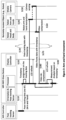
- Fig. 2 shows the method for measuring an MTP latency for a head and/or a body movement according to an embodiment of the invention.
- step S10 When an MR user triggers the first moment to move the user's head and/or body, the movement is detected in step S10 by using an orientation and pose tracking sensor mounted on an MR HMD glass device.
- the orientation and pose tracking sensor may sense an orientation and pose change such as an orientation change of the user's head, a pose change of the user's head, a horizontal or vertical movement of the user's head and/or body and so on.
- step S20 time information associated with the pose and/or orientation tracking data is assigned to the pose and/or orientation tracking data, for example in a form of a time stamp by a teleoperation client software running in a processor.
- the processor may be configured in an MR HDM glass or a 5G smartphone in a 5G smartphone-tethered MR model.
- step S30 the pose and/or orientation tracking data is transferred along with the time information assigned to the pose and/or orientation tracking data to a remotely located object so that it can control the operation of the remotely located object.
- the remotely located object such as a robot equipped with a mobile camera receives the pose and/or orientation tracking data together with the time information.
- a processor at the teleoperation object may change the orientation and position of the robot head and/or robot body based on the orientation and pose tracking data that represent the movement of the MR user's head and/or body.
- the processor may be mounted on the robot head and/orthe robot body.
- the mobile camera captures in step S50 all RGB signals of the robot head and/or the robot body in a form of video data while each orientation and pose tracking data is kept synchronized with each image frame.
- step S60 image frames are compressed by a video encoder at the teleoperation object and transmitted in step S70 to the MR HMD glass device along with the time information (e.g. the time stamp) associated with the orientation and pose tracking data synchronized with the image frames via a 5G network environment.
- time information e.g. the time stamp
- the encoded image frames are received at the teleoperation client.
- the processor at the teleoperation client decodes the received image frames using a video decoder in step S80 and send to a display panel (e.g. an LCD) in the MR HMD glass device.
- a display panel e.g. an LCD
- the processor measures the MTP latency in step S90 using the time information associated with the motion tracking data and the time information associated with the image data. For example, the processor may retrieve and compare the time difference between time information on the time stamp and the time information representing the time when the image frame is sent to the display panel.
- Fig. 3 shows the method for measuring an MTP latency for an arm and/or a hand movement according to an embodiment of the invention.
- the embodiment according to Fig. 3 differs from the embodiment according to Fig. 2 in that instead of a head and/or a body movement, an arm and/or a hand movement is sensed.
- a pose tracking sensor mounted on a further MR accessory device other than an MR HMD glass device such as an MR controller is used.
- the steps S110, S120, ..., S190 in Fig. 3 correspond to the steps S10, S20, ..., S90 of the embodiment according to Fig. 2 except for differences explained in the following.
- the pose tracking data may be generated at the pose tracking sensor implemented in an MR controller and sent to the processor in an MR HMD glass device via a Bluetooth connection.
- the latency caused by the Bluetooth connection between the MR controller or any other MR accessory devices and the MR HMD glass or a 5G smartphone in a 5G smartphone-tethered MR model may be estimated and included as an offset when the time information is assigned by a processor in the MR HMD glass device in step S120.
- the pose tracking data is sent to a processor at the teleoperation object in step S140 for controlling robot arms and hands to manipulate them as being synchronized with the MR user's arm and hand motion.
- the processor at the teleoperation object may be mounted on the robot arm and/or the robot hand.
- the mobile camera captures in step S150 all RGB signals of the robot's arm and/or robot's hand in a form of video data while each pose tracking data is kept synchronized with each image frame.
Landscapes
- Engineering & Computer Science (AREA)
- Robotics (AREA)
- Mechanical Engineering (AREA)
- Image Analysis (AREA)
Abstract
Description
- The present invention relates to a method, means, a teleoperation client and a teleoperation object for objectively measuring and monitoring a motion-to-photon (MTP) latency in a teleoperation system with a remote vision-through mixed reality (MR).
- An MTP latency is an end-to-end latency that is accumulated from the latency of each of transactions in a teleoperation system with a remote vision-through MR. An MTP latency is one of the main factors that bring a direct impact on a Quality of Experience (QoE) while the system is in operation. In general, such a teleoperation system with a remote vision-through MR consists of multiple transactions and processes, for instance, including motion-sensing and tracking, mobile camera sensing, physical movement of an object, video encoding, video decoding, network transmission, local asynchronous warping, and so on. Each of these multiple transactions shall cause transaction latencies that are accumulated to increase an end-to-end MTP latency.
- A teleoperation system with a remote vision-through MR is getting more attention since a demand from the industry has increased in many domains such as tele-driving of automotive, teleoperation of industrial robots and teleoperation of drones. Furthermore, the advent of 5G mobile networks with many innovative technologies, such as network slicing technology and adaptively managed latency, can intensify an improved mobility of remotely located objects in terms of a wider coverage and shorter latency. In every teleoperation system with a remote vision-through MR, the MTP latency is a very critical QoE parameter which affects the service quality directly. For example, if the MTP latency is not short enough while the system is in operation, then an MR user cannot operate remotely located objects conveniently since all the refreshed screens shown on the MR display panel will be displayed with longer lags between the MR user's head, body, arm or hand motions and remotely located object's corresponding movement. However, the measurement of an MTP latency is a very complicated task since such an MTP latency is a summation of series of partial latencies caused in each of separated transactions and separated hardware devices. Furthermore, those partial latencies are accumulated through multiple network connectivity. Therefore, traditionally, the MTP latency measurement was conducted in a labor-centric way, i.e., by taking pictures of the MR user's motions and those of the remotely located object's corresponding movement with high-speed cameras and comparing them to count an MTP latency in millisecond(s).
- This measurement method based on a high-speed camera has several problems and restrictions. Firstly, it cannot measure the MTP latency precisely since it is highly dependent on a human's perception. Secondly, it cannot provide a systematic measurement in a real-time basis so that it can support neither real-time-based monitoring nor log data accumulation.
- It is thus an object of the present invention to provide a method and means, a teleoperation client and a teleoperation object for measuring an MTP latency in an objective way which obviate disadvantages of the MTP latency measurement methods according to the prior art.
- According to an aspect of the invention, a method for measuring a motion-to-photon, MTP, latency in a teleoperation system is provided, comprising: obtaining motion tracking data for a motion of a first object at a teleoperation client, assigning first time information to the motion tracking data, transmitting the motion tracking data and the first time information from the teleoperation client to a teleoperation object, controlling a motion of a second object using the motion tracking data at the teleoperation object, obtaining image data for the motion of the second object based on the motion tracking data at the teleoperation object, obtaining second time information associated with the image data, and measuring an MTP latency based on the first time information and the second time information. Thus, an MTP latency may be objectively measured by managing time information in end-to-end transactions. For instance, the method may provide an MTP latency which starts from the moment of a first object's motion (e.g. an MR user's motion) and ends by the moment of an image frame refresh on a display panel at a teleoperation client by using the first time information assigned at the moment of the first object's motion while obtaining the motion tracking data and the second time information obtained at the moment of the refresh of the image frame for the motion of the second object controlled based on the motion tracking data of the first object's motion. Further, an MTP latency may be measured on a real-time basis which enables the data to be continuously generated and fed into a QoE management means for further data accumulation and data mining analysis.
- According to a further aspect of the invention, the first time information may indicate the time at which the motion tracking data for a motion of a first object is obtained at the teleoperation client and/or the time at which the motion tracking data for a motion of a first object is transmitted from the teleoperation client to the teleoperation object. As the first time information is associated with an action, the first time information can be assigned in a simple manner, e.g. by using a time stamp when the corresponding action is occurred. Further, an estimated time offset may be used alternatively or in addition, if a partial latency which cannot be measured by using a time stamp needs be taken into account in the MTP latency measurement.
- Preferably, the method for measuring a motion-to-photon, MTP, latency further comprises: encoding the image data at the teleoperation object, transmitting the encoded image data from the teleoperation object to the teleoperation client, decoding the image data at the teleoperation client and sending the image data to a display controller at the teleoperation client and/or at the teleoperation object.
- According to a further aspect of the invention, the second time information may indicate the time at which the image data for the motion of the second object is generated at the teleoperation object and/or the time at which the image data for the motion of the second object is transmitted from the teleoperation object to the teleoperation client and/or the time at which the image data is sent to a/the display controller at the teleoperation client. As the second time information is associated with an action, the second time information can be assigned in a simple manner, e.g. by using a time stamp when the corresponding action is occurred. Further, an estimated time offset may be used alternatively or in addition, if a partial latency which cannot be measured by using a time stamp needs be taken into account in the MTP latency measurement.
- According to a further aspect of the invention, the measuring an MTP latency may comprise retrieving the first time information and the second time information and calculating a difference between the first time information and the second time information.
- Preferably, the measuring an MTP latency is carried out at the teleoperation client and/or at the teleoperation object and/or at a monitoring point. Thus, the MTP latency measured can be fed to a centralized QoE management system at the teleoperation client and/or at the teleoperation object and/or at a monitoring point for further analysis including data accumulation and data mining analysis.
- According to a further aspect of the invention, the motion of a first object comprises at least one of: an orientation change of the first object, a pose change of the first object and a movement of the first object, wherein the first object comprises a human body or a part of a human body such as a head, a body, an arm, a hand or a combination thereof. For a head and/or a body motion, an orientation and pose tracking sensor may preferably be used to detect the motion. The orientation and pose tracking sensor may be mounted on an MR Head Mounted Device, HMD, glass device at the teleoperation client. For an arm and/or a hand motion, a pose tracking sensor may preferably be used to detect the motion. The pose tracking sensor may be mounted on an MR controller at the teleoperation client. Thus, an MTP latency may be measured across multiple hardware devices such as an MR HMD glass, an MR controller and remotely located objects. Further, the multiple hardware devices may operate in various network environments such as 5G mobile networks.
- According to a further aspect of the invention, the second object comprises a robot body or a part of a robot body such as a robot head, a robot body, a robot arm, a hand or a combination thereof.
- According to an aspect of the invention, means for measuring a motion-to-photon, MTP, latency in a teleoperation system is provided for measuring the MTP latency according to the method of any of preceding aspects.
- According to an aspect of the invention, a teleoperation client for measuring a motion-to-photon, MTP, latency in a teleoperation system is provided, comprising: a processor configured to obtain motion tracking data for a motion of a first object and to assign first time information to the motion tracking data, a transmitter configured to transmit the motion tracking data and the first time information to a teleoperation object, and a receiver configured to receive image data from the teleoperation object, wherein the processor is further configured to: obtain second time information associated with the received image data and measure an MTP latency based on the first time information and the second time information.
- Preferably, the teleoperation client further comprises one or more sensors for sensing a motion of a first object, and a display controller. Preferably, the teleoperation client further comprises a Mixed Reality, MR, controller, the MR controller comprising a/the sensor for sensing an orientation change and/or a pose change, and/or a Mixed Reality, MR, Head Mounted Display, HMD, glass device, the MR HMD glass device comprising the processor and/or a/the sensor for sensing an orientation change and/or a pose change.
- According to an aspect of the invention, a teleoperation object for measuring a motion-to-photon, MTP, latency in a teleoperation system, comprising: a receiver configured to receive motion tracking data and first time information from the teleoperation client, a processor configured to control a motion of a second object using the motion tracking data, a sensing device configured to obtain image data for the motion of the second object based on the motion tracking data, the processor and/or the sensing device being configured to obtain second time information associated with the image data, and a transmitter configured to transmit the image data and the second time information. The sensing device may be a mobile camera.
- Preferably, the processor is further configured to measure the MTP latency based on the first time information and the second time information.
- Preferably, the second object comprises a robot or a part of a robot such as a robot head, a robot body, a robot arm and/or a robot hand.
- Other aspects, features, and advantages will be apparent from the summary above, as well as from the description that follows, including the figures and the claims.
-
- Fig. 1
- shows an overview of a teleoperation system in which the method for measuring an MTP latency according to an embodiment of the invention can be applied.
- Fig. 2
- shows the method for measuring an MTP latency for a head and/or a body movement according to an embodiment of the invention.
- Fig. 3
- shows the method for measuring an MTP latency for an arm and/or a hand movement according to an embodiment of the invention.
-
Fig. 1 shows an overview of a teleoperation system in which the method for measuring an MTP latency according to an embodiment of the invention can be applied. - A teleoperation system comprises a teleoperation client and a teleoperation object. The teleoperation client may comprise a first
motion tracking sensor 7, aprocessor 9 and adisplay controller 11. The firstmotion tracking sensor 7 may be mounted on an MRHMD glass device 1 for sensing a motion of an MR user (a first object). The firstmotion tracking sensor 7 may comprise a 3 up to 6 Degrees of Freedom (DoF) sensor(s) which may be an orientation and/or tracking sensor for sensing a head and/or body movement of the MR user. Preferably, theprocessor 9 and thedisplay controller 11 are configured in the MR HMD glass device. In another embodiment, however, theprocessor 9 and thedisplay controller 11 may be configured in a separate device such as a 5G smartphone. - The
processor 9 preferably configured in an MR HMDglass device 1 may be connected to anMR controller 5 via a communication network such as Bluetooth. On the MR controller 5 a second motion tracking sensor 13 may be mounted for sensing a movement of the MR user. For example, the MR controller may be held by hand or attached on an arm of the MR user. The second motion tracking sensor 13 mounted on theMR controller 5 may comprise a 3 up to 6 Degrees of Freedom (DoF) sensor which is an orientation and/or pose tracking sensor for sensing an arm and/or hand movement of the MR user. - The first and/or the second
motion tracking sensor 7, 13 may generate motion tracking data representing the motion of the MR user. The motion tracking data generated by the motion tracking sensor 13 of theMR controller 5 may be transmitted to theprocessor 9 of the MRHMD glass device 1 via the communication network such as Bluetooth. - Time information associated with motion tracking data is assigned to the motion tracking data representing the motion of the MR user sensed by the motion tracking sensor(s) 7, 13. If the first time information indicates the time at which the motion tracking data is obtained at the teleoperation client, the first time information may be assigned by the motion tracking sensor(s) 7, 13 by using a time stamp when the motion of the first object is sensed. Alternatively or additionally, the first time information may be assigned by the
processor 9 by using a time stamp at the time of reception of the motion tracking data obtained by the motion tracking sensor(s) 7, 13 are received at the processor. If the first time information indicates the time at which the motion tracking data is transmitted from the teleoperation client to the teleoperation object, the first time information may be assigned by theprocessor 9 by using a time stamp at the time of transmission. - Thus, when an MR user triggers the first moment to move the MR user's head and/or body or arm(s) and/or hand(s), time information is assigned to the pose and/or orientation tracking data as first time information associated with the movement. The time information assignment may be carried out by a teleoperation client software running in an MR HDM glass or 5G smartphone in a 5G smartphone-tethered MR model. Further, the motion tracking data along with the time information may be stored at the teleoperation client.
- Further, the motion tracking data along with time information is transferred from the teleoperation client to a teleoperation object for controlling the motion of a second object at the teleoperation object. If the teleoperation object comprises a remotely-located
robot 3, the second object may be a robot head and/orbody 15 and/or robot arm(s) and/or hand(s) 19. The teleoperation object further comprises amobile camera 19 which may be equipped with therobot 3. - A processor at the teleoperation object (e.g. mounted on the robot) controls the motion of the second object based on the received motion tracking data representing the motion of the first objects. If the teleoperation object comprises robot arms and
hands 17, they may be manipulated as synchronized with the MR user's arm and hand motion. At this moment, themobile camera 19 senses the motion of the second object by capturing RGB signals and generates image frames as, e.g. video data, while the motion tracking data is kept synchronized with each image frame. That is, obtaining image data for the motion of the second object is carried out based on the received motion tracking data by synchronization of the controlling the motion of the second object and the obtaining the image data. Each image frame generated by themobile camera 19 may be compressed by a video encoder of the processor at the teleoperation object and transmitted to the teleoperation client via a communication network, e.g. a 5G network. - The
processor 9 at the teleoperation client may decode the encoded video data received. The video data decoded may comprise the image frames synchronized with the motion tracking data and the first time information. Theprocessor 9 at the teleoperation client may push the video data to thedisplay controller 11 to be displayed at a display panel preferably configured in theMR glass device 1. Theprocessor 9 may measure the MTP latency by retrieving and comparing the time difference between the first time information, e.g. a timestamp information included in the motion tracking data, and the current time at the time of transmission of the video data to the display controller. Alternatively or additionally, a (further) partial latency such as a latency incurred from transmission of the video data to display of the video data on the display panel may be estimated and added as an offset. - Thus, motion tracking data obtained at the teleoperation client is kept and managed together with the time information through the end-to-end transaction across the network environment and the remotely operated objects until the final refreshed image data is ready to be transferred to the display panel via a display port or any other standard interfaces. An MTP latency may be measured by managing the time information associated with the motion tacking data and the time information associated with the image data in end-to-end transactions.
- In this example, the time information associated with the image data indicates the time at which the image data is sent to a display controller at the teleoperation client. Alternatively or additionally, the second time information may indicate the time at which the image data for the motion of the second object is generated at the teleoperation object and/or the time at which the image data for the motion of the second object is transmitted from the teleoperation object to the teleoperation client.
- If the second time information indicates the time at which the image data for the motion of the second object is generated at the teleoperation object, the second time information may be generated by using a time stamp at the time of capturing RGB signals at the mobile camera or using a time stamp at the time of encoding image frames at the processor. If the second time information indicates the time at which the image data for the motion of the second object is transmitted from the teleoperation object to the teleoperation client, the second time information may be generated by using a time stamp at the time of transmission of the image frame generated or encoded.
-
Fig. 2 shows the method for measuring an MTP latency for a head and/or a body movement according to an embodiment of the invention. - When an MR user triggers the first moment to move the user's head and/or body, the movement is detected in step S10 by using an orientation and pose tracking sensor mounted on an MR HMD glass device. The orientation and pose tracking sensor may sense an orientation and pose change such as an orientation change of the user's head, a pose change of the user's head, a horizontal or vertical movement of the user's head and/or body and so on. In step S20, time information associated with the pose and/or orientation tracking data is assigned to the pose and/or orientation tracking data, for example in a form of a time stamp by a teleoperation client software running in a processor. The processor may be configured in an MR HDM glass or a 5G smartphone in a 5G smartphone-tethered MR model.
- In step S30, the pose and/or orientation tracking data is transferred along with the time information assigned to the pose and/or orientation tracking data to a remotely located object so that it can control the operation of the remotely located object. The remotely located object such as a robot equipped with a mobile camera receives the pose and/or orientation tracking data together with the time information.
- In step S40, a processor at the teleoperation object may change the orientation and position of the robot head and/or robot body based on the orientation and pose tracking data that represent the movement of the MR user's head and/or body. The processor may be mounted on the robot head and/orthe robot body. At this moment, the mobile camera captures in step S50 all RGB signals of the robot head and/or the robot body in a form of video data while each orientation and pose tracking data is kept synchronized with each image frame.
- In step S60, image frames are compressed by a video encoder at the teleoperation object and transmitted in step S70 to the MR HMD glass device along with the time information (e.g. the time stamp) associated with the orientation and pose tracking data synchronized with the image frames via a 5G network environment.
- The encoded image frames are received at the teleoperation client. The processor at the teleoperation client decodes the received image frames using a video decoder in step S80 and send to a display panel (e.g. an LCD) in the MR HMD glass device.
- The processor measures the MTP latency in step S90 using the time information associated with the motion tracking data and the time information associated with the image data. For example, the processor may retrieve and compare the time difference between time information on the time stamp and the time information representing the time when the image frame is sent to the display panel.
-
Fig. 3 shows the method for measuring an MTP latency for an arm and/or a hand movement according to an embodiment of the invention. - The embodiment according to
Fig. 3 differs from the embodiment according toFig. 2 in that instead of a head and/or a body movement, an arm and/or a hand movement is sensed. In the embodiment according toFig. 3 , thus, a pose tracking sensor mounted on a further MR accessory device other than an MR HMD glass device such as an MR controller is used. The steps S110, S120, ..., S190 inFig. 3 correspond to the steps S10, S20, ..., S90 of the embodiment according toFig. 2 except for differences explained in the following. - In step S110, the pose tracking data may be generated at the pose tracking sensor implemented in an MR controller and sent to the processor in an MR HMD glass device via a Bluetooth connection. The latency caused by the Bluetooth connection between the MR controller or any other MR accessory devices and the MR HMD glass or a 5G smartphone in a 5G smartphone-tethered MR model may be estimated and included as an offset when the time information is assigned by a processor in the MR HMD glass device in step S120.
- The pose tracking data is sent to a processor at the teleoperation object in step S140 for controlling robot arms and hands to manipulate them as being synchronized with the MR user's arm and hand motion. The processor at the teleoperation object may be mounted on the robot arm and/or the robot hand. At this moment, the mobile camera captures in step S150 all RGB signals of the robot's arm and/or robot's hand in a form of video data while each pose tracking data is kept synchronized with each image frame.
- What has been described and illustrated herein are embodiments of the invention along with some of variations. The terms, descriptions and figures used herein are set forth by way of illustration only and are not meant as limitations. Those skilled in the art will recognize that many variations are possible within the scope of the invention, which is intended to be defined by the following claims - and their equivalents - in which all terms are meant in their broadest reasonable sense unless otherwise indicated. In particular, the present invention covers further embodiments with any combination of features from different embodiments described above.
- Furthermore, in the claims the word "comprising" does not exclude other elements or steps, and the indefinite article "a" or "an" does not exclude a plurality. A single unit may fulfil the functions of several features recited in the claims. Any reference signs in the claims should not be construed as limiting the scope.
Claims (15)
- A method for measuring a motion-to-photon, MTP, latency in a teleoperation system, comprising:obtaining (S10, S110) motion tracking data for a motion of a first object at a teleoperation client,assigning (S20, S120) first time information to the motion tracking data,transmitting (S30, S130) the motion tracking data and the first time information from the teleoperation client to a teleoperation object,controlling (S40, S140) a motion of a second object using the motion tracking data at the teleoperation object,obtaining image data (S50, S150) for the motion of the second object based on the motion tracking data at the teleoperation object,obtaining (S50, S90, S150, S190) second time information associated with the image data, andmeasuring (S90, S190) an MTP latency based on the first time information and the second time information.
- The method of claim 1, wherein the first time information indicates the time at which the motion tracking data for a motion of a first object is obtained at the teleoperation client and/or the time at which the motion tracking data for a motion of a first object is transmitted from the teleoperation client to the teleoperation object.
- The method of claim 1 or 2, further comprising:encoding (S60, S160) the image data at the teleoperation object,transmitting (S70, S170) the encoded image data from the teleoperation object to the teleoperation client,decoding (S80, S180) the image data at the teleoperation client andsending the image data to a display controller at the teleoperation client and/or at the teleoperation object.
- The method of any one of claims 1 to 3, wherein the second time information indicates the time at which the image data for the motion of the second object is generated at the teleoperation object and/or the time at which the image data for the motion of the second object is transmitted from the teleoperation object to the teleoperation client and/or the time at which the image data is sent to a/the display controller at the teleoperation client.
- The method of any one of claims 1 to 4, wherein the measuring an MTP latency comprises retrieving the first time information and the second time information and calculating a difference between the first time information and the second time information.
- The method of any one of claims 1 to 5, wherein the measuring an MTP latency is carried out at the teleoperation client and/or at the teleoperation object and/or at a monitoring point.
- The method of any one of claims 1 to 6, wherein the motion of a first object comprises at least one of: an orientation change of the first object, a pose change of the first object and a movement of the first object, wherein the first object comprises a human body or a part of a human body.
- The method of any one of claims 1 to 7, wherein the second object comprises a robot body or a part of a robot body.
- Means for measuring a motion-to-photon, MTP, latency in a teleoperation system according to any one of claims 1 to 8.
- A teleoperation client for measuring a motion-to-photon, MTP, latency in a teleoperation system, comprising:a processor (9) configured to obtain motion tracking data for a motion of a first object and to assign first time information to the motion tracking data,a transmitter configured to transmit the motion tracking data and the first time information to a teleoperation object, anda receiver configured to receive image data from the teleoperation object,wherein the processor (9) is further configured to:obtain second time information associated with the received image dataand
measure an MTP latency based on the first time information and the second time information. - The teleoperation client according to claim 10, further comprising one or more sensors (7, 13) for sensing a motion of a first object, and a display controller (11).
- The teleoperation client according to claim 10 or 11, further comprising a Mixed Reality, MR, controller (5), the MR controller comprising a/the sensor (13) for sensing an orientation change and/or a pose change, and/or a Mixed Reality, MR, Head Mounted Display, HMD, glass device (1), the MR HMD glass device comprising the processor (9) and/or a/the sensor (7) for sensing an orientation change and/or a pose change.
- A teleoperation object for measuring a motion-to-photon, MTP, latency in a teleoperation system, comprising:a receiver configured to receive motion tracking data and first time information from the teleoperation client,a processor configured to control a motion of a second object (15, 17) using the motion tracking data,a sensing device (19) configured to obtain image data for the motion of the second object based on the motion tracking data, the processor and/or the sensing device being configured to obtain second time information associated with the image data, anda transmitter configured to transmit the image data and the second time information.
- The teleoperation object according to claim 13, wherein the processor is further configured to measure the MTP latency based on the first time information and the second time information.
- The teleoperation object according to claim 13 or 14, wherein the second object (15, 17) comprises a robot or a part of robot.
Priority Applications (1)
| Application Number | Priority Date | Filing Date | Title |
|---|---|---|---|
| EP21210443.4A EP4186649B1 (en) | 2021-11-25 | 2021-11-25 | Method of objective mtp latency measurement in a tele-operation with remote vision-through mr |
Applications Claiming Priority (1)
| Application Number | Priority Date | Filing Date | Title |
|---|---|---|---|
| EP21210443.4A EP4186649B1 (en) | 2021-11-25 | 2021-11-25 | Method of objective mtp latency measurement in a tele-operation with remote vision-through mr |
Publications (2)
| Publication Number | Publication Date |
|---|---|
| EP4186649A1 true EP4186649A1 (en) | 2023-05-31 |
| EP4186649B1 EP4186649B1 (en) | 2026-04-29 |
Family
ID=79025188
Family Applications (1)
| Application Number | Title | Priority Date | Filing Date |
|---|---|---|---|
| EP21210443.4A Active EP4186649B1 (en) | 2021-11-25 | 2021-11-25 | Method of objective mtp latency measurement in a tele-operation with remote vision-through mr |
Country Status (1)
| Country | Link |
|---|---|
| EP (1) | EP4186649B1 (en) |
Cited By (4)
| Publication number | Priority date | Publication date | Assignee | Title |
|---|---|---|---|---|
| CN119105921A (en) * | 2024-11-08 | 2024-12-10 | 舜宇光学(浙江)研究院有限公司 | Delay test method, delay detection device, electronic device and storage medium |
| CN119165964A (en) * | 2024-11-08 | 2024-12-20 | 舜宇光学(浙江)研究院有限公司 | Delay measurement method and system, electronic device, storage medium, program product |
| WO2026098360A1 (en) * | 2024-11-08 | 2026-05-15 | 舜宇光学(浙江)研究院有限公司 | Delay measurement method and system, calibration method and system, delay test method and system, electronic device, storage medium, and program product |
| WO2026130376A1 (en) * | 2024-12-16 | 2026-06-25 | 万有引力(宁波)电子科技有限公司 | Latency detection method and apparatus, device, storage medium, and program product |
Citations (1)
| Publication number | Priority date | Publication date | Assignee | Title |
|---|---|---|---|---|
| US20150117466A1 (en) * | 2013-10-24 | 2015-04-30 | Harris Corporation | Latency smoothing for teleoperation systems |
-
2021
- 2021-11-25 EP EP21210443.4A patent/EP4186649B1/en active Active
Patent Citations (1)
| Publication number | Priority date | Publication date | Assignee | Title |
|---|---|---|---|---|
| US20150117466A1 (en) * | 2013-10-24 | 2015-04-30 | Harris Corporation | Latency smoothing for teleoperation systems |
Cited By (6)
| Publication number | Priority date | Publication date | Assignee | Title |
|---|---|---|---|---|
| CN119105921A (en) * | 2024-11-08 | 2024-12-10 | 舜宇光学(浙江)研究院有限公司 | Delay test method, delay detection device, electronic device and storage medium |
| CN119165964A (en) * | 2024-11-08 | 2024-12-20 | 舜宇光学(浙江)研究院有限公司 | Delay measurement method and system, electronic device, storage medium, program product |
| CN119165964B (en) * | 2024-11-08 | 2025-06-24 | 舜宇光学(浙江)研究院有限公司 | Delay measurement method and system, electronic device, storage medium and program product |
| CN119105921B (en) * | 2024-11-08 | 2025-06-24 | 舜宇光学(浙江)研究院有限公司 | Delay test method, delay detection device, electronic device and storage medium |
| WO2026098360A1 (en) * | 2024-11-08 | 2026-05-15 | 舜宇光学(浙江)研究院有限公司 | Delay measurement method and system, calibration method and system, delay test method and system, electronic device, storage medium, and program product |
| WO2026130376A1 (en) * | 2024-12-16 | 2026-06-25 | 万有引力(宁波)电子科技有限公司 | Latency detection method and apparatus, device, storage medium, and program product |
Also Published As
| Publication number | Publication date |
|---|---|
| EP4186649B1 (en) | 2026-04-29 |
Similar Documents
| Publication | Publication Date | Title |
|---|---|---|
| EP4186649B1 (en) | Method of objective mtp latency measurement in a tele-operation with remote vision-through mr | |
| US8903317B2 (en) | System and method for controlling an infrared camera using a mobile phone | |
| EP1566038B1 (en) | Methods and systems for transferring events including multimedia data | |
| US9829873B2 (en) | Method and data presenting device for assisting a remote user to provide instructions | |
| US7657106B2 (en) | Switching device for sharing input/output devices and computer system using the same | |
| CN1209540A (en) | Remote controlled measuring system | |
| US20160353057A1 (en) | Techniques to overcome communication lag between terminals performing video mirroring and annotation operations | |
| US20050137827A1 (en) | System and method for managing arrangement position and shape of device | |
| JP2004102027A5 (en) | ||
| US20180103072A1 (en) | Method and apparatus for session control support for field of view virtual reality streaming | |
| KR20140062174A (en) | Systems and methods for hands free inspection | |
| JP6218471B2 (en) | IMAGING DEVICE, EXTERNAL DEVICE, IMAGING SYSTEM, IMAGING DEVICE CONTROL METHOD, EXTERNAL DEVICE CONTROL METHOD, IMAGING SYSTEM CONTROL METHOD, AND PROGRAM | |
| EP2713605B1 (en) | Vision angle acquisition method, apparatus and system | |
| JP2015220693A (en) | Imaging apparatus, imaging system, control method therefor, and program | |
| JP2000032437A (en) | Image transmission system | |
| KR20260000547A (en) | System and method for visual enablement of a real-time location system | |
| JP5230401B2 (en) | Display control device, image processing device | |
| JP2007053717A (en) | Security monitoring system capable of outputting still image | |
| JP6815978B2 (en) | Initial setting method for remote monitoring system and monitored equipment | |
| US20090059015A1 (en) | Information processing device and remote communicating system | |
| JP2012186591A (en) | Camera controller, camera control method, and camera control program | |
| JP2010055263A (en) | Monitoring control system | |
| JP2006211459A (en) | Video output system and control program for outputting video | |
| JP2015220692A (en) | Imaging apparatus, information processing apparatus, imaging system, control method therefor, and program | |
| JP2002374522A (en) | Monitoring system data setting method and monitoring system using the same |
Legal Events
| Date | Code | Title | Description |
|---|---|---|---|
| PUAI | Public reference made under article 153(3) epc to a published international application that has entered the european phase |
Free format text: ORIGINAL CODE: 0009012 |
|
| STAA | Information on the status of an ep patent application or granted ep patent |
Free format text: STATUS: REQUEST FOR EXAMINATION WAS MADE |
|
| 17P | Request for examination filed |
Effective date: 20220922 |
|
| AK | Designated contracting states |
Kind code of ref document: A1 Designated state(s): AL AT BE BG CH CY CZ DE DK EE ES FI FR GB GR HR HU IE IS IT LI LT LU LV MC MK MT NL NO PL PT RO RS SE SI SK SM TR |
|
| GRAP | Despatch of communication of intention to grant a patent |
Free format text: ORIGINAL CODE: EPIDOSNIGR1 |
|
| STAA | Information on the status of an ep patent application or granted ep patent |
Free format text: STATUS: GRANT OF PATENT IS INTENDED |
|
| INTG | Intention to grant announced |
Effective date: 20260129 |
|
| GRAS | Grant fee paid |
Free format text: ORIGINAL CODE: EPIDOSNIGR3 |
|
| GRAA | (expected) grant |
Free format text: ORIGINAL CODE: 0009210 |
|
| STAA | Information on the status of an ep patent application or granted ep patent |
Free format text: STATUS: THE PATENT HAS BEEN GRANTED |
|
| AK | Designated contracting states |
Kind code of ref document: B1 Designated state(s): AL AT BE BG CH CY CZ DE DK EE ES FI FR GB GR HR HU IE IS IT LI LT LU LV MC MK MT NL NO PL PT RO RS SE SI SK SM TR |
|
| REG | Reference to a national code |
Ref country code: CH Ref legal event code: F10 Free format text: ST27 STATUS EVENT CODE: U-0-0-F10-F00 (AS PROVIDED BY THE NATIONAL OFFICE) Effective date: 20260429 Ref country code: GB Ref legal event code: FG4D |
|
| REG | Reference to a national code |
Ref country code: DE Ref legal event code: R096 Ref document number: 602021053013 Country of ref document: DE |
|
| REG | Reference to a national code |
Ref country code: IE Ref legal event code: FG4D |