JP2004102027A5 - - Google Patents
Download PDFInfo
- Publication number
- JP2004102027A5 JP2004102027A5 JP2002265441A JP2002265441A JP2004102027A5 JP 2004102027 A5 JP2004102027 A5 JP 2004102027A5 JP 2002265441 A JP2002265441 A JP 2002265441A JP 2002265441 A JP2002265441 A JP 2002265441A JP 2004102027 A5 JP2004102027 A5 JP 2004102027A5
- Authority
- JP
- Japan
- Prior art keywords
- image display
- edid
- display device
- image
- display system
- Prior art date
- Legal status (The legal status is an assumption and is not a legal conclusion. Google has not performed a legal analysis and makes no representation as to the accuracy of the status listed.)
- Granted
Links
Images
Description
【0019】
続いて、PC10と各画像表示装置11,12,13間の通信方式について説明する。先ず、PC10のDDCによるEDIDの取得方法は従来の通信方式と同じであり、PC10と画像表示装置11間のデータの受け渡しは、PC10の管理・制御手段101と画像表示装置11の入力側データ送受信手段111によるDDCを用いた通信手順に従って行われ、管理・制御手段101は装置情報記憶保持手段112に記憶されているEDIDを取得する。PC10の管理・制御手段101によって取得されたEDIDは、前述の手順で各画像表示装置11,12,13から抽出して記憶されたEDIDであるので、PC10は、マルチモニタ環境下の共通EDIDとして情報を取得することになる。[0019]
Subsequently, a communication method between the PC 10 and each of the image display devices 11 , 12, 13 will be described. First, the method for acquiring the EDID by the DDC of the PC 10 is the same as the conventional communication method, and the data transfer between the PC 10 and the image display device 11 is performed by transmitting / receiving data on the input side of the management / control means 101 of the PC 10 and the image display device 11 It is performed according to the communication procedure using DDC by means 111, and the management and control means 101 acquires the EDID stored in the device information storage holding means 112. Since the EDID acquired by the management and control means 101 of the PC 10 is an EDID extracted and stored from each of the image display devices 11, 12, and 13 in the above-described procedure, the PC 10 is used as a common EDID under a multi-monitor environment. It will get information.
【0021】
図2(b)の処理手順に沿ってEDIDの取得過程を簡単に説明すると、画像表示装置13は、出力側に画像表示装置が接続されていないのでEDIDの取得データはなく、EDIDの変更なしとして自己のEDIDを画像表示装置12へ送出する(ステップS1)。画像表示装置12は、画像表示装置13から取得したEDIDと自己のEDIDとを比較して共通のEDIDを抽出し、画像表示装置12と画像表示装置13の共通のEDIDを共通EDIDとして画像表示装置11へ送出する(ステップS2)。画像表示装置11は、画像表示装置12から取得したEDIDと自己のEDIDとを比較して共通のEDIDを抽出し、画像表示装置11、画像表示装置12、および画像表示装置13の共通EDIDとしてPC10へ送出する(ステップS3)。これによって、PC10は、取得したEDIDを、画像表示装置11、画像表示装置12、および画像表示装置13の共通EDIDとして認識し、このマルチモニタ環境下に最適な解像度、リフレッシュレートの信号を画像表示装置11へ出力する(ステップS4)。[0021]
The process of acquiring the EDID will be briefly described according to the processing procedure of FIG. 2B. The image display apparatus 13 has no image display apparatus connected to the output side, there is no acquired data of EDID, and there is no change in the EDID. And sends its own EDID to the image display 12 (step S1). The image display device 12 compares the EDID acquired from the image display device 13 with its own EDID to extract a common EDID, and the image display device 12 uses the common EDID of the image display device 12 and the image display device 13 as a common EDID. 11. Send to 11 (step S2). The image display device 11 compares the EDID acquired from the image display device 12 with its own EDID to extract a common EDID, and uses the PC 10 as a common EDID of the image display device 11, the image display device 12, and the image display device 13. It sends out to (step S3). Thus, PC 10 the acquired EDID, the image display device 11 is recognized as a common EDID of the image display device 12 and the image display device 13, the best resolution under the multi-monitor environments, image display signal refresh rate Output to the device 11 (step S4).
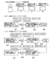
【0029】
図4は、図1に示す画像表示システムが装置制御に関するコマンド解析処理を行う場合の説明図であり、(a)はPCと複数の画像表示装置の接続図、(b)はデータ設定のDDC−CIコマンドの流れを示す図、(c)はデータ取得のDDC−CIコマンドの流れを示す図である。つまり、この図は、第1の実施の形態において、画像表示システムが装置番号の付加されたDDC−CIコマンドの解析処理を行う例として示したものである。[0029]
FIG. 4 is an explanatory diagram when the image display system shown in FIG. 1 performs command analysis processing related to device control, (a) is a connection diagram of a PC and a plurality of image display devices, (b) is a data setting DDC. diagram showing the flow of -CI command, (c) is a diagram showing a flow of a DDC-CI command data acquisition. That is, in the first embodiment, this figure is shown as an example in which the image display system analyzes the DDC-CI command to which the device number is added.
【0039】
画像信号入力端子62は、インデックス信号が画像信号の一部を置き換えて付加された画像信号と、この画像信号に同期した垂直および水平の各同期信号とを複合化信号として入力される。画像信号出力端子63は、画像信号入力手段62に入力された画像信号の一部を画像表示システムから外部へ出力する。画像信号受信手段60は、複数の画像フレームよりなる画像信号、この画像信号に対応する同期信号、および画像信号の任意の画像フレームに画像信号の一部を置き換えて付加されたインデックス信号を含む複合化信号を受信し、受信した複合化信号より画像信号、同期信号、及び複合化信号を分離して出力する。画像信号出力手段61は、画像信号受信手段60へ入力される画像信号の一部を外部へ出力する。[0039]
Image signal input terminal 62 is input and the image signal index signal is added by replacing a part of the image signal, and the synchronizing signal of the vertical and horizontal synchronized with the image signal as a composite signal. The image signal output terminal 63 outputs part of the image signal input to the image signal input means 62 from the image display system to the outside. The image signal receiving unit 60 includes an image signal including a plurality of image frames, a synchronization signal corresponding to the image signal, and a compound including an index signal added by replacing a part of the image signal with an arbitrary image frame of the image signal. The modulation signal is received, and the image signal, the synchronization signal, and the composite signal are separated and output from the received composite signal. The image signal output unit 61 outputs a part of the image signal input to the image signal receiving unit 60 to the outside.
【0045】
第4の実施の形態
図7は、本発明の第4の実施の形態における画像表示システムの構成とその動作の流れを示す図である。つまり、この図は、本発明に適用された通信方式を用いた画像表示システムと動作の流れを概略的に示している。DDCによるEDIDデータの読み込み手段と、DDC−CIと呼ばれる画像表示装置制御手段を備えたPC70が、本発明に適用された通信方式を備える画像表示装置71,72、73を直列に接続している。また、7A,7B、7Cは、画像表示装置73の接続なし/電源OFF/電源ONといった各状態の監視状態を示した図である。[0045]
Fourth Embodiment FIG. 7 is a diagram showing the configuration of an image display system according to a fourth embodiment of the present invention and the flow of the operation thereof. That is, this figure schematically shows the flow of an image display system and an operation using the communication method applied to the present invention. A PC 70 having a means for reading EDID data by DDC and an image display device control means called DDC-CI serially connects image display devices 71, 72, 73 having a communication method applied to the present invention. . Further, 7A, 7B, 7C are diagrams showing monitoring states of respective states such as no connection / power OFF / power ON of the image display device 73.
【0050】
第5の実施の形態
図8は、本発明の第5の実施の形態における画像表示システムの構成とその動作の流れを示す図であり、(a)はインデックス番号設定前の画像表示システムの接続構成図、(b)はインデックス番号設定手順を示すフロー図、(c)はインデックス番号設定後の画像表示システムの接続構成図を示す。つまり、この図は、特開2000−352962号公報に示す画像表示システムに、本発明の通信方式を付加した画像表示システムとその動作の流れを概略的に示している。[0050]
Fifth Embodiment FIG. 8 is a diagram showing the configuration of an image display system according to a fifth embodiment of the present invention and the flow of the operation thereof, and (a) shows connection of the image display system before setting the index number. (B) is a flowchart showing an index number setting procedure, (c) shows a connection configuration diagram of the image display system after setting the index number. That is, this figure schematically shows an image display system in which the communication method of the present invention is added to the image display system shown in Japanese Patent Laid-Open No. 2000-352962 and the flow of the operation thereof.
【0054】
ここで、インデックス番号を自動で設定するために、先ず、PC80から、インデックス信号を用いたインデックス番号自動設定コマンドが各画像表示装置81,82…8nへ送信される(ステップS51)。これによって、n台の画像表示装置81,82…8nはインデックス番号自動設定コマンドを受信するが、n台の中でPC80に最も近い場所で接続されている画像表示装置81がインデックス番号1を取得して設定し、さらに、DDCを用いて、画像表示装置82に対してインデックス番号2を設定するコマンドを送信する(ステップS52)。なお、画像表示装置81自身がPC80に最も近い所で接続された画像表示装置であるか否かについては、上記の各実施の形態で述べたように、本発明の画像表示装置は相互の通信手段を持っているため、画像表示装置の入力側に画像表示装置間のみで行われる通信データが来なかったり、各画像表示装置が出力側に何台接続されているかを調べることなどによって判断することができる。[0054]
Here, in order to automatically set the index number, first, an index number automatic setting command using an index signal is transmitted from the PC 80 to each of the image display devices 81, 82... 8n (step S51). .. 8 n receives an index number automatic setting command, but the image display device 81 connected at the place closest to the PC 80 among the n sets acquires the index number 1 , And further transmits a command for setting the index number 2 to the image display device 82 using the DDC (step S52). As to whether or not the image display device 81 itself is the image display device connected closest to the PC 80, as described in the above embodiments, the image display devices of the present invention communicate with each other. Since it has a means, it is judged whether communication data performed only between the image display devices does not come to the input side of the image display device, or by checking how many image display devices are connected to the output side. be able to.
【0060】
また、本発明の画像表示システムによれば、上述のような動作により、各画像表示装置の接続状態や電源OFF/ON状態を把握することができるため、PCは、画像表示装置の台数を管理する手段を備えたり、何らかの障害で画像表示装置が電源OFFされたり、接続中に切断されたりといったトラブルをユーザへ通知することができるため、より使い易いマルチモニタ環境の画像表示システムを提供することができる。[0060]
Further, according to the image display system of the present invention, the connection state and the power OFF / ON state of each image display device can be grasped by the operation as described above, so the PC manages the number of image display devices. To provide a user-friendly image display system in a multi-monitor environment, since it is possible to notify the user of troubles such as when the image display device is turned off due to some failure or disconnected during connection. Can.
【図面の簡単な説明】
【図1】本発明の第1の実施の形態における画像表示システムの構成を示すブロック図である。
【図2】図1に示す画像表示システムが行うEDIDの処理の流れを示す説明図であり、(a)はPCと複数の画像表示装置の接続図、(b)はEDIDの取得手順を示す図である。
【図3】図1に示す画像表示システムにおける装置制御に関するコマンド解析処理の流れを示すフローチャートである。
【図4】図1に示す画像表示システムが装置制御に関するコマンド解析処理を行う場合の説明図であり、(a)はPCと複数の画像表示装置の接続図、(b)はデータ設定のDDC−CIコマンドの流れを示す図、(c)はデータ取得のDDC−CIコマンドの流れを示す図である。
【図5】本発明の第2の実施の形態における画像表示システムの装置制御の手順を示す図であり、(a)は画像表示システムの接続状態を示す図、(b)は各画像表示装置の電源OFFの処理の流れを示す図である。
【図6】本発明の第3の実施の形態における画像表示システムの構成を示すブロック図である。
【図7】本発明の第4の実施の形態における画像表示システムの構成とその動作の流れを示す図である。
【図8】本発明の第5の実施の形態における画像表示システムの構成とその動作の流れを示す図であり、(a)はインデックス番号設定前の画像表示システムの接続構成図、(b)はインデックス番号設定手順を示すフロー図、(c)はインデックス番号設定後の画像表示システムの接続構成図を示す。
【符号の説明】
10,50,70,80…PC、11,12,13,51,52〜5n,71,72,73,81,82〜80n…画像表示装置、101…管理・制御手段、111,121,131…入力側データ送受信手段、112,122,132…装置情報記憶保持手段、113,123,133…MPU判定処理手段、114,124,134…MPU用記憶保持手段、115,125,135…出力側データ送受信手段、62…画像信号入力端子、63…画像信号出力端子、60…画像信号受信手段、61…画像信号出力手段、64…インデックス判別手段、65…インデックス判定手段、66…画像表示装置番号設定手段、67…フレーム選択手段、68…画像記憶手段、69…画像表示手段、6A…制御情報判定手段、6B…装置制御手段、6C…入力側通信手段、6D…出力側通信手段。Brief Description of the Drawings
FIG. 1 is a block diagram showing a configuration of an image display system according to a first embodiment of the present invention.
2 is an explanatory view showing a flow of processing of EDID performed by the image display system shown in FIG. 1, (a) is a connection diagram of a PC and a plurality of image display devices, (b) shows an acquisition procedure of EDID. FIG.
FIG. 3 is a flow chart showing a flow of command analysis processing relating to device control in the image display system shown in FIG. 1;
4 is an explanatory view of a case where the image display system shown in FIG. 1 performs command analysis processing relating to device control, (a) is a connection diagram of a PC and a plurality of image display devices, (b) is a data setting DDC diagram showing the flow of -CI command, (c) is a diagram showing a flow of a DDC-CI command data acquisition.
FIG. 5 is a diagram showing a procedure of device control of the image display system according to the second embodiment of the present invention, wherein (a) is a diagram showing a connection state of the image display system, (b) is each image display device It is a figure which shows the flow of a process of the power supply OFF of.
FIG. 6 is a block diagram showing a configuration of an image display system according to a third embodiment of the present invention.
FIG. 7 is a diagram showing the configuration of an image display system according to a fourth embodiment of the present invention and the flow of the operation thereof.
FIG. 8 is a diagram showing the configuration of an image display system according to a fifth embodiment of the present invention and the flow of the operation thereof, wherein (a) is a connection configuration diagram of the image display system before index number setting, (b) Is a flowchart showing an index number setting procedure, and (c) shows a connection configuration diagram of the image display system after setting the index number.
[Description of the code]
10, 50, 70, 80 ... PC, 11, 12, 13, 51, 52 to 5 n, 71, 72, 73, 81, 82 to 80 n ... Image display apparatus, 101 ... Management and control means, 111, 121, 131 ... Input side data transmission / reception means, 112, 122, 132 ... Device information storage holding means, 113, 123, 133 ... MPU judgment processing means, 114, 124, 134 ... MPU storage holding means, 115, 125, 135 ... Output side Data transmitting / receiving means 62: image signal input terminal 63: image signal output terminal 60: image signal receiving means 61: image signal output means 64: index discriminating means 65: index discriminating means 66: image display device number Setting means 67: frame selection means 68: image storage means 69: image display means 6A: control information determination means 6B: device control means C ... input-side communication means, 6D ... output-side communication means.
Priority Applications (4)
| Application Number | Priority Date | Filing Date | Title |
|---|---|---|---|
| JP2002265441A JP3795442B2 (en) | 2002-09-11 | 2002-09-11 | Image display system |
| DE10341566A DE10341566B4 (en) | 2002-09-11 | 2003-09-09 | Image display system |
| DE10362250A DE10362250B4 (en) | 2002-09-11 | 2003-09-09 | Image display system |
| US10/659,177 US7358928B2 (en) | 2002-09-11 | 2003-09-10 | Image display system |
Applications Claiming Priority (1)
| Application Number | Priority Date | Filing Date | Title |
|---|---|---|---|
| JP2002265441A JP3795442B2 (en) | 2002-09-11 | 2002-09-11 | Image display system |
Publications (3)
| Publication Number | Publication Date |
|---|---|
| JP2004102027A JP2004102027A (en) | 2004-04-02 |
| JP2004102027A5 true JP2004102027A5 (en) | 2005-03-17 |
| JP3795442B2 JP3795442B2 (en) | 2006-07-12 |
Family
ID=31944488
Family Applications (1)
| Application Number | Title | Priority Date | Filing Date |
|---|---|---|---|
| JP2002265441A Expired - Fee Related JP3795442B2 (en) | 2002-09-11 | 2002-09-11 | Image display system |
Country Status (3)
| Country | Link |
|---|---|
| US (1) | US7358928B2 (en) |
| JP (1) | JP3795442B2 (en) |
| DE (2) | DE10341566B4 (en) |
Families Citing this family (59)
| Publication number | Priority date | Publication date | Assignee | Title |
|---|---|---|---|---|
| US7329179B2 (en) * | 2001-09-21 | 2008-02-12 | Igt | Gaming device having wager dependent bonus game play |
| JP2004333522A (en) * | 2003-04-30 | 2004-11-25 | Sony Corp | Picture display device |
| US20050219147A1 (en) * | 2004-03-25 | 2005-10-06 | Pioneer Plasma Display Corporation | Display device, display support program and display support method |
| JP4677733B2 (en) * | 2004-04-15 | 2011-04-27 | ソニー株式会社 | Server device, display device, and display method |
| US7903045B2 (en) * | 2004-04-30 | 2011-03-08 | Microsoft Corporation | Video presenting network supporting separately-configurable resources |
| US7898533B2 (en) * | 2004-04-30 | 2011-03-01 | Microsoft Corporation | Video presenting network configuration solution space traversal |
| US8581803B2 (en) * | 2004-04-30 | 2013-11-12 | Microsoft Corporation | Video presenting network management |
| US7679612B2 (en) * | 2004-04-30 | 2010-03-16 | Microsoft Corporation | Configuration goals via video presenting network |
| JP4707966B2 (en) * | 2004-05-06 | 2011-06-22 | 三菱電機株式会社 | Large video display device |
| KR101079599B1 (en) * | 2004-08-06 | 2011-11-03 | 삼성전자주식회사 | Display apparatus and control method thereof |
| US20060095811A1 (en) * | 2004-09-15 | 2006-05-04 | Damon Afualo | Apparatus and method for graphics memory controlling hub (GMCH) clocking support for dual television encoders |
| JP4615276B2 (en) * | 2004-09-21 | 2011-01-19 | シャープ株式会社 | Content data distribution apparatus and content data distribution system |
| TW200614066A (en) * | 2004-10-29 | 2006-05-01 | Hon Hai Prec Ind Co Ltd | Method for automatically modifying the refresh rate |
| KR100831141B1 (en) * | 2004-11-25 | 2008-05-20 | 마쯔시다덴기산교 가부시키가이샤 | Repeater apparatus and method for controlling the same |
| US7450084B2 (en) | 2004-12-17 | 2008-11-11 | Microsoft Corporation | System and method for managing computer monitor configurations |
| US7826710B2 (en) | 2005-01-13 | 2010-11-02 | Panasonic Corporation | Playback device, computer program, playback method |
| JP4513592B2 (en) * | 2005-02-09 | 2010-07-28 | 日本電気株式会社 | Computer switching device, computer switching method used therefor, and program therefor |
| JP4426492B2 (en) * | 2005-03-30 | 2010-03-03 | Ykk株式会社 | Programmable terminal system |
| KR100720652B1 (en) * | 2005-09-08 | 2007-05-21 | 삼성전자주식회사 | Display driving circuit |
| US20090046210A1 (en) * | 2005-10-31 | 2009-02-19 | Matsushita Electric Industrial Co., Ltd. | Audiovisual system |
| JP4929952B2 (en) | 2006-09-28 | 2012-05-09 | 船井電機株式会社 | Digital broadcast recording device |
| JP4163732B2 (en) * | 2006-12-05 | 2008-10-08 | 株式会社ナナオ | Display system and display device |
| KR101380753B1 (en) | 2007-07-23 | 2014-04-02 | 삼성전자 주식회사 | Display apparatus and control method of the same |
| JP2009055149A (en) * | 2007-08-24 | 2009-03-12 | Sony Corp | Electronic apparatus |
| KR100841434B1 (en) * | 2007-09-03 | 2008-06-25 | 삼성전자주식회사 | Image display device and method for changing edid information thereof |
| US8723756B2 (en) | 2008-01-15 | 2014-05-13 | Synaptics Incorporated | System having capability for daisy-chained serial distribution of video display data |
| JP2009237375A (en) * | 2008-03-27 | 2009-10-15 | Toshiba Corp | Display system, its display control device, and image providing device |
| US8237624B2 (en) * | 2008-05-06 | 2012-08-07 | Integrated Device Technology, Inc. | System having capability for daisy-chained serial distribution of video display data |
| JP5170242B2 (en) * | 2008-06-02 | 2013-03-27 | Necディスプレイソリューションズ株式会社 | Video display system |
| JP5448576B2 (en) * | 2008-06-03 | 2014-03-19 | キヤノン株式会社 | Display control apparatus, display control method, and program |
| WO2010007751A1 (en) * | 2008-07-14 | 2010-01-21 | パナソニック株式会社 | Video data processing device and video data processing method |
| JP5008088B2 (en) * | 2008-08-01 | 2012-08-22 | 株式会社ナナオ | Display system, display control apparatus, and computer program |
| KR101466122B1 (en) * | 2008-10-21 | 2014-11-27 | 삼성전자 주식회사 | Display apparatus, multi display system and control method of the same |
| WO2010073363A1 (en) * | 2008-12-26 | 2010-07-01 | 富士通株式会社 | Resolution changing device, resolution changing method, and resolution changing program |
| CN102349289B (en) | 2009-03-11 | 2015-04-22 | 惠普开发有限公司 | Color space matching of video signals |
| US9348355B2 (en) | 2009-08-24 | 2016-05-24 | Ati Technologies Ulc | Display link clocking method and apparatus |
| US9760333B2 (en) * | 2009-08-24 | 2017-09-12 | Ati Technologies Ulc | Pixel clocking method and apparatus |
| JP5335641B2 (en) * | 2009-10-19 | 2013-11-06 | キヤノン株式会社 | Information processing apparatus and image display method |
| WO2011117930A1 (en) * | 2010-03-26 | 2011-09-29 | Necディスプレイソリューションズ株式会社 | Display device, method for transmitting transmission information, program and display system |
| US20110242142A1 (en) * | 2010-03-30 | 2011-10-06 | Ati Technologies Ulc | Multiple display chrominance and luminance method and apparatus |
| JP5510927B2 (en) * | 2010-05-19 | 2014-06-04 | シャープ株式会社 | Display system, display, and display method |
| US8531352B2 (en) * | 2010-06-15 | 2013-09-10 | Synaptics Incorporated | Dynamic EDID generation |
| CN101894536A (en) * | 2010-06-26 | 2010-11-24 | 大连捷成实业发展有限公司 | Application method capable of enabling all displays connected to matrix to display normally |
| JP2012083572A (en) * | 2010-10-12 | 2012-04-26 | Canon Inc | Display system and control method |
| CN102074190A (en) * | 2010-12-29 | 2011-05-25 | 深圳市中庆微科技开发有限公司 | Light emitting diode (LED) network control system |
| BR112013012350A2 (en) * | 2010-12-30 | 2016-08-30 | Thomson Licensing | method and apparatus for use in low power RF circuits and edid data and control for viewer monitoring |
| JP2011103006A (en) * | 2011-01-13 | 2011-05-26 | Mitsubishi Electric Corp | Large video display apparatus |
| WO2013005328A1 (en) * | 2011-07-07 | 2013-01-10 | Necディスプレイソリューションズ株式会社 | Display system |
| CN103246316A (en) * | 2012-02-07 | 2013-08-14 | 联想(北京)有限公司 | Information processing device and method |
| JP6149394B2 (en) * | 2012-03-21 | 2017-06-21 | セイコーエプソン株式会社 | Projector and projector system |
| JP5701820B2 (en) * | 2012-06-08 | 2015-04-15 | 三菱電機株式会社 | Image display panel, display panel control device, and image display device |
| CN103391470A (en) * | 2013-07-10 | 2013-11-13 | Tcl通力电子(惠州)有限公司 | Method and device for switching information sources automatically |
| CN104793701B (en) * | 2015-04-07 | 2018-07-03 | 联想(北京)有限公司 | A kind of information processing method and equipment |
| US10102884B2 (en) * | 2015-10-22 | 2018-10-16 | International Business Machines Corporation | Distributed serialized data buffer and a memory module for a cascadable and extended memory subsystem |
| TWI578162B (en) * | 2015-11-25 | 2017-04-11 | 光遠科技股份有限公司 | Method for sending indication to displayers connected in series |
| US10509614B2 (en) | 2015-12-25 | 2019-12-17 | Maxell, Ltd. | Video display apparatus-apparatus communication |
| JP6867396B2 (en) * | 2016-08-30 | 2021-04-28 | シャープNecディスプレイソリューションズ株式会社 | Display device, display setting method of display device, and display setting program of display device |
| JP6693342B2 (en) * | 2016-08-31 | 2020-05-13 | セイコーエプソン株式会社 | Display system and method of controlling display system |
| WO2018116399A1 (en) * | 2016-12-21 | 2018-06-28 | Necディスプレイソリューションズ株式会社 | Image display device, connection method of image display device, and multi-display system |
Family Cites Families (15)
| Publication number | Priority date | Publication date | Assignee | Title |
|---|---|---|---|---|
| US5375245A (en) * | 1993-02-22 | 1994-12-20 | Tandberg Data A/S | Apparatus for automatically reducing the power consumption of a CRT computer monitor |
| JPH0888820A (en) | 1994-09-20 | 1996-04-02 | Fujitsu General Ltd | Multi-panel display system |
| JPH09128330A (en) * | 1995-11-06 | 1997-05-16 | Sony Corp | Video display device |
| US6049316A (en) * | 1997-06-12 | 2000-04-11 | Neomagic Corp. | PC with multiple video-display refresh-rate configurations using active and default registers |
| US5987614A (en) * | 1997-06-17 | 1999-11-16 | Vadem | Distributed power management system and method for computer |
| US6370603B1 (en) * | 1997-12-31 | 2002-04-09 | Kawasaki Microelectronics, Inc. | Configurable universal serial bus (USB) controller implemented on a single integrated circuit (IC) chip with media access control (MAC) |
| CN1154896C (en) * | 1998-04-27 | 2004-06-23 | 迪吉多电子股份有限公司 | Control system, display, host computer for control, and data transmitting method |
| US6473078B1 (en) * | 1999-05-26 | 2002-10-29 | Nokia Display Products Oy | Method and device for power consumption management of an integrated display unit |
| JP4172096B2 (en) * | 1999-06-14 | 2008-10-29 | 三菱電機株式会社 | Image signal generating device, image display device, and control method for image display device |
| US6404423B1 (en) * | 1999-07-09 | 2002-06-11 | Nokia Display Products Oy | Method for display power management and monitor equipped with a power management function |
| JP3468288B2 (en) | 1999-11-30 | 2003-11-17 | インターナショナル・ビジネス・マシーンズ・コーポレーション | Host device, image display device, image display system, image display method, panel attribute readout method, and image display control method |
| US7012576B2 (en) * | 1999-12-29 | 2006-03-14 | Intel Corporation | Intelligent display interface |
| JP3408781B2 (en) | 2000-06-14 | 2003-05-19 | 株式会社ナナオ | Display device distribution device |
| JP2002196717A (en) | 2000-12-26 | 2002-07-12 | Nec Corp | Method for controlling luminance level of multiscreen |
| JP2004102063A (en) * | 2002-09-11 | 2004-04-02 | Canon Inc | Image display device, its control method and multi-display system |
-
2002
- 2002-09-11 JP JP2002265441A patent/JP3795442B2/en not_active Expired - Fee Related
-
2003
- 2003-09-09 DE DE10341566A patent/DE10341566B4/en not_active Expired - Fee Related
- 2003-09-09 DE DE10362250A patent/DE10362250B4/en not_active Expired - Fee Related
- 2003-09-10 US US10/659,177 patent/US7358928B2/en not_active Expired - Fee Related
Similar Documents
| Publication | Publication Date | Title |
|---|---|---|
| JP2004102027A5 (en) | ||
| JP3795442B2 (en) | Image display system | |
| US8042145B2 (en) | Method of controlling power states in a multimedia system | |
| US8085310B2 (en) | Image capturing apparatus and power supply control method therefor | |
| CN101426078A (en) | Video switcher and video switching method | |
| KR100209525B1 (en) | Operation board remote i/o communication controlling system | |
| WO2015001664A1 (en) | Device for displaying plurality of displays | |
| CN101510939A (en) | Image transfer device, image display apparatus, and image data transfer method | |
| JP2007053717A (en) | Security monitoring system capable of outputting still image | |
| KR100949814B1 (en) | Monitoring system for totally remotely managing multiple uninterrupted power supplys | |
| US20070043881A1 (en) | Data bus monitoring and controlling system and method | |
| JPH1175176A (en) | Remote supervisory system and remote supervisory method | |
| CN106603537A (en) | System and method for marking video signal source of mobile intelligent terminal | |
| US20040160438A1 (en) | A security ratings system | |
| JP2019083378A (en) | Imaging apparatus | |
| JP5061925B2 (en) | Image compression distribution apparatus and image compression distribution method | |
| KR100952462B1 (en) | Video monitoring system and video monitoring method for performing being able to control local and remote video in the same time | |
| CN101674449B (en) | Method for controlling graphical interface of user by camera and camera | |
| JP2012222687A (en) | Server device | |
| CN112714272A (en) | Inter-device control method, terminal, and computer-readable storage medium | |
| JP5683859B2 (en) | Screen receiving device, screen receiving method and screen receiving program | |
| JP2006203817A (en) | Multicamera system | |
| KR100494572B1 (en) | Method for controlling foreign media source device using bridge function | |
| US20130058624A1 (en) | Network control device, display device, and network control method | |
| JPH06153204A (en) | Electronic camera and photographic device using the same |