EP4186599B1 - Mehrkammerzerstäuber - Google Patents
Mehrkammerzerstäuber Download PDFInfo
- Publication number
- EP4186599B1 EP4186599B1 EP22205763.0A EP22205763A EP4186599B1 EP 4186599 B1 EP4186599 B1 EP 4186599B1 EP 22205763 A EP22205763 A EP 22205763A EP 4186599 B1 EP4186599 B1 EP 4186599B1
- Authority
- EP
- European Patent Office
- Prior art keywords
- compartment
- drum
- sprayer according
- casing
- distributor
- Prior art date
- Legal status (The legal status is an assumption and is not a legal conclusion. Google has not performed a legal analysis and makes no representation as to the accuracy of the status listed.)
- Active
Links
Images


Classifications
-
- B—PERFORMING OPERATIONS; TRANSPORTING
- B05—SPRAYING OR ATOMISING IN GENERAL; APPLYING FLUENT MATERIALS TO SURFACES, IN GENERAL
- B05B—SPRAYING APPARATUS; ATOMISING APPARATUS; NOZZLES
- B05B11/00—Single-unit hand-held apparatus in which flow of contents is produced by the muscular force of the operator at the moment of use
- B05B11/01—Single-unit hand-held apparatus in which flow of contents is produced by the muscular force of the operator at the moment of use characterised by the means producing the flow
- B05B11/10—Pump arrangements for transferring the contents from the container to a pump chamber by a sucking effect and forcing the contents out through the dispensing nozzle
- B05B11/1081—Arrangements for pumping several liquids or other fluent materials from several containers, e.g. for mixing them at the moment of pumping
-
- B—PERFORMING OPERATIONS; TRANSPORTING
- B05—SPRAYING OR ATOMISING IN GENERAL; APPLYING FLUENT MATERIALS TO SURFACES, IN GENERAL
- B05B—SPRAYING APPARATUS; ATOMISING APPARATUS; NOZZLES
- B05B12/00—Arrangements for controlling delivery; Arrangements for controlling the spray area
- B05B12/14—Arrangements for controlling delivery; Arrangements for controlling the spray area for supplying a selected one of a plurality of liquids or other fluent materials or several in selected proportions to a spray apparatus, e.g. to a single spray outlet
- B05B12/1472—Arrangements for controlling delivery; Arrangements for controlling the spray area for supplying a selected one of a plurality of liquids or other fluent materials or several in selected proportions to a spray apparatus, e.g. to a single spray outlet separate supply lines supplying different materials to separate outlets of the spraying apparatus
-
- B—PERFORMING OPERATIONS; TRANSPORTING
- B05—SPRAYING OR ATOMISING IN GENERAL; APPLYING FLUENT MATERIALS TO SURFACES, IN GENERAL
- B05B—SPRAYING APPARATUS; ATOMISING APPARATUS; NOZZLES
- B05B12/00—Arrangements for controlling delivery; Arrangements for controlling the spray area
- B05B12/14—Arrangements for controlling delivery; Arrangements for controlling the spray area for supplying a selected one of a plurality of liquids or other fluent materials or several in selected proportions to a spray apparatus, e.g. to a single spray outlet
- B05B12/1409—Arrangements for controlling delivery; Arrangements for controlling the spray area for supplying a selected one of a plurality of liquids or other fluent materials or several in selected proportions to a spray apparatus, e.g. to a single spray outlet the selection means being part of the discharge apparatus, e.g. part of the spray gun
-
- B—PERFORMING OPERATIONS; TRANSPORTING
- B05—SPRAYING OR ATOMISING IN GENERAL; APPLYING FLUENT MATERIALS TO SURFACES, IN GENERAL
- B05B—SPRAYING APPARATUS; ATOMISING APPARATUS; NOZZLES
- B05B9/00—Spraying apparatus for discharge of liquids or other fluent material, without essentially mixing with gas or vapour
- B05B9/01—Spray pistols, discharge devices
-
- B—PERFORMING OPERATIONS; TRANSPORTING
- B05—SPRAYING OR ATOMISING IN GENERAL; APPLYING FLUENT MATERIALS TO SURFACES, IN GENERAL
- B05B—SPRAYING APPARATUS; ATOMISING APPARATUS; NOZZLES
- B05B1/00—Nozzles, spray heads or other outlets, with or without auxiliary devices such as valves, heating means
- B05B1/14—Nozzles, spray heads or other outlets, with or without auxiliary devices such as valves, heating means with multiple outlet openings; with strainers in or outside the outlet opening
- B05B1/16—Nozzles, spray heads or other outlets, with or without auxiliary devices such as valves, heating means with multiple outlet openings; with strainers in or outside the outlet opening having selectively- effective outlets
- B05B1/169—Nozzles, spray heads or other outlets, with or without auxiliary devices such as valves, heating means with multiple outlet openings; with strainers in or outside the outlet opening having selectively- effective outlets having three or more selectively effective outlets
-
- B—PERFORMING OPERATIONS; TRANSPORTING
- B05—SPRAYING OR ATOMISING IN GENERAL; APPLYING FLUENT MATERIALS TO SURFACES, IN GENERAL
- B05B—SPRAYING APPARATUS; ATOMISING APPARATUS; NOZZLES
- B05B11/00—Single-unit hand-held apparatus in which flow of contents is produced by the muscular force of the operator at the moment of use
- B05B11/01—Single-unit hand-held apparatus in which flow of contents is produced by the muscular force of the operator at the moment of use characterised by the means producing the flow
- B05B11/10—Pump arrangements for transferring the contents from the container to a pump chamber by a sucking effect and forcing the contents out through the dispensing nozzle
- B05B11/1001—Piston pumps
- B05B11/1009—Piston pumps actuated by a lever
-
- B—PERFORMING OPERATIONS; TRANSPORTING
- B05—SPRAYING OR ATOMISING IN GENERAL; APPLYING FLUENT MATERIALS TO SURFACES, IN GENERAL
- B05B—SPRAYING APPARATUS; ATOMISING APPARATUS; NOZZLES
- B05B11/00—Single-unit hand-held apparatus in which flow of contents is produced by the muscular force of the operator at the moment of use
- B05B11/01—Single-unit hand-held apparatus in which flow of contents is produced by the muscular force of the operator at the moment of use characterised by the means producing the flow
- B05B11/10—Pump arrangements for transferring the contents from the container to a pump chamber by a sucking effect and forcing the contents out through the dispensing nozzle
- B05B11/1042—Components or details
- B05B11/1052—Actuation means
- B05B11/1056—Actuation means comprising rotatable or articulated levers
- B05B11/1057—Triggers, i.e. actuation means consisting of a single lever having one end rotating or pivoting around an axis or a hinge fixedly attached to the container, and another end directly actuated by the user
-
- B—PERFORMING OPERATIONS; TRANSPORTING
- B05—SPRAYING OR ATOMISING IN GENERAL; APPLYING FLUENT MATERIALS TO SURFACES, IN GENERAL
- B05B—SPRAYING APPARATUS; ATOMISING APPARATUS; NOZZLES
- B05B11/00—Single-unit hand-held apparatus in which flow of contents is produced by the muscular force of the operator at the moment of use
- B05B11/01—Single-unit hand-held apparatus in which flow of contents is produced by the muscular force of the operator at the moment of use characterised by the means producing the flow
- B05B11/10—Pump arrangements for transferring the contents from the container to a pump chamber by a sucking effect and forcing the contents out through the dispensing nozzle
- B05B11/1081—Arrangements for pumping several liquids or other fluent materials from several containers, e.g. for mixing them at the moment of pumping
- B05B11/1084—Arrangements for pumping several liquids or other fluent materials from several containers, e.g. for mixing them at the moment of pumping each liquid or other fluent material being pumped by a separate pump
-
- B—PERFORMING OPERATIONS; TRANSPORTING
- B05—SPRAYING OR ATOMISING IN GENERAL; APPLYING FLUENT MATERIALS TO SURFACES, IN GENERAL
- B05B—SPRAYING APPARATUS; ATOMISING APPARATUS; NOZZLES
- B05B15/00—Details of spraying plant or spraying apparatus not otherwise provided for; Accessories
-
- B—PERFORMING OPERATIONS; TRANSPORTING
- B05—SPRAYING OR ATOMISING IN GENERAL; APPLYING FLUENT MATERIALS TO SURFACES, IN GENERAL
- B05B—SPRAYING APPARATUS; ATOMISING APPARATUS; NOZZLES
- B05B15/00—Details of spraying plant or spraying apparatus not otherwise provided for; Accessories
- B05B15/60—Arrangements for mounting, supporting or holding spraying apparatus
- B05B15/65—Mounting arrangements for fluid connection of the spraying apparatus or its outlets to flow conduits
-
- B—PERFORMING OPERATIONS; TRANSPORTING
- B05—SPRAYING OR ATOMISING IN GENERAL; APPLYING FLUENT MATERIALS TO SURFACES, IN GENERAL
- B05B—SPRAYING APPARATUS; ATOMISING APPARATUS; NOZZLES
- B05B7/00—Spraying apparatus for discharge of liquids or other fluent materials from two or more sources, e.g. of liquid and air, of powder and gas
- B05B7/24—Spraying apparatus for discharge of liquids or other fluent materials from two or more sources, e.g. of liquid and air, of powder and gas with means, e.g. a container, for supplying liquid or other fluent material to a discharge device
- B05B7/2402—Apparatus to be carried on or by a person, e.g. by hand; Apparatus comprising containers fixed to the discharge device
- B05B7/2472—Apparatus to be carried on or by a person, e.g. by hand; Apparatus comprising containers fixed to the discharge device comprising several containers
-
- B—PERFORMING OPERATIONS; TRANSPORTING
- B05—SPRAYING OR ATOMISING IN GENERAL; APPLYING FLUENT MATERIALS TO SURFACES, IN GENERAL
- B05B—SPRAYING APPARATUS; ATOMISING APPARATUS; NOZZLES
- B05B7/00—Spraying apparatus for discharge of liquids or other fluent materials from two or more sources, e.g. of liquid and air, of powder and gas
- B05B7/24—Spraying apparatus for discharge of liquids or other fluent materials from two or more sources, e.g. of liquid and air, of powder and gas with means, e.g. a container, for supplying liquid or other fluent material to a discharge device
- B05B7/2489—Spraying apparatus for discharge of liquids or other fluent materials from two or more sources, e.g. of liquid and air, of powder and gas with means, e.g. a container, for supplying liquid or other fluent material to a discharge device an atomising fluid, e.g. a gas, being supplied to the discharge device
- B05B7/2497—Spraying apparatus for discharge of liquids or other fluent materials from two or more sources, e.g. of liquid and air, of powder and gas with means, e.g. a container, for supplying liquid or other fluent material to a discharge device an atomising fluid, e.g. a gas, being supplied to the discharge device several liquids from different sources being supplied to the discharge device
-
- B—PERFORMING OPERATIONS; TRANSPORTING
- B05—SPRAYING OR ATOMISING IN GENERAL; APPLYING FLUENT MATERIALS TO SURFACES, IN GENERAL
- B05B—SPRAYING APPARATUS; ATOMISING APPARATUS; NOZZLES
- B05B9/00—Spraying apparatus for discharge of liquids or other fluent material, without essentially mixing with gas or vapour
- B05B9/03—Spraying apparatus for discharge of liquids or other fluent material, without essentially mixing with gas or vapour characterised by means for supplying liquid or other fluent material
Definitions
- the object of the present invention is comprised within the sector of spraying products devices with multiple containers.
- the proposed sprayer is configured for dispensing products, preferably fluids, independently housed in said containers.
- document US20100282776 proposes a device for selectively dispensing several fluids that are stored separately from one another such that the final use product is mixed on demand during dispensing.
- Document IT BO20 120 211 A1 discloses another example of multi-compartment sprayer.
- the invention relates to a multi-compartment sprayer.
- the key to said sprayer is that it comprises a rotary movement assembly that allows the user to conveniently select a product to be sprayed from among the plurality of products contained in the sprayer.
- the sprayer comprises an outer casing in which the containers for the products are located and in which movable equipment and fixed equipment are provided, wherein the movable equipment comprises the rotary movement assembly and an unlocking movement assembly in charge of allowing or blocking the product selection rotary movement.
- the rotary movement assembly comprises a plurality of nozzles, configured for spraying the products from the conduits; a distributor drum which connects the conduits with the corresponding nozzles and allows passage therethrough only in the position selected by the user; a drum cover which is attached to the distributor drum to fix the position of the components that may be arranged therein such as, for example, nozzles; and a product selection wheel which is the element actuated by the user to select the product to be sprayed.
- the fixed equipment of the sprayer comprises a fixed casing with a fixed casing cover and the guide shaft about which the rotary movement assembly rotates and along which the unlocking movement assembly moves to allow or prevent the movement of the rotary movement assembly.
- the fixed equipment also includes a trigger to actuate the sprayer.
- the product selection wheel is concealed in the outer casing of the sprayer.
- the movable body is unlocked and emerges on the rear part of the outer casing to enable the selection of the product. Only the nozzle positioned in the lower part of the drum can be actuated. The spray nozzle protrudes through the front part of the trigger. Unobstructed spraying is thereby ensured.
- the trigger has a housing which coincides with the support for actuating the spray nozzle.
- the nozzle In the spray position, the nozzle goes through the trigger, therefore, in order to be able to change the product, it will be necessary to move the movable equipment backwards, releasing the drum and facilitating the rotary movement. To select the product to be sprayed, the drum rotates, integral with the product selection wheel, until the desired product is available.
- the movable body is fixed, such that it allows the plunger of the corresponding metering system to travel and to return by means of a spring.
- the assembly is locked/released by means of the locking button located in the rear part of the sprayer.
- the movable body has a groove in the lower rear part in which the locking button fits when locking is to be performed. Moving the button downwards releases the movable body, which emerges as a result of the action of the wheel output spring.
- the product can be selected. To that end, simply turning the wheel in any direction will suffice. Once the product has been chosen, there is a need to press the rear part of the wheel until the movable body is completely concealed.
- the locking system will automatically fix the body as a result of a spring comprised in the locking button and exerting a restoring force that directs it towards the inside of the groove in the movable casing.
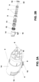
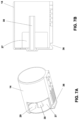
- FIGS 1A-B depict the multi-compartment sprayer (1) of the invention in perspective views from different angles.
- the sprayer (1) comprises a main body with an outer casing (23) which covers and protects movable equipment (2), fixed equipment (16), and a plurality of compartments in which products to be sprayed, generally fluids, are housed.
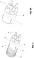
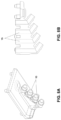
- Figures 2A-B show the movable equipment (2).
- Said movable equipment in turn comprises a rotary movement assembly (3) that can be seen in Figure 3 and the elements of which have also been depicted in Figures 4A-D , 5A-B , and 6, and comprises an unlocking movement assembly (4) the elements of which have been depicted in Figures 7A-B and 8A-B .
- the rotary movement assembly (3) of Figure 3 is configured for rotating about a guide shaft (19) of the sprayer (1). This movement allows selecting the product to be sprayed, that is, selecting from which compartment spraying is to be performed.
- the rotary movement assembly (3) comprises a plurality of nozzles (6), connected to corresponding metering systems (7) housed in cavities (9) of a distributor drum (38), and comprises a drum cover (10) which, in an embodiment like the one shown in the figures, has a plurality of holes through which the nozzles (6) pass.
- the nozzles (6) preferably comprise stops (24) to ensure their position between the distributor drum (38) and the drum cover (10).
- stops (24) and the cavities (9) have a flat face such that the rotation of the piston of the metering system (7) is prevented and the correct position of the nozzle (6) with respect to the spraying trigger (20) which will be described below is maintained at all times.
- the diameter of the nozzle (6) is slightly smaller than the diameter of the piston of the corresponding metering system (7), just enough so that the plunger of the piston can move freely. The plunger is therefore fully guided. This sizing prevents unwanted play in the plunger, thereby lengthening the service life of the components.
- the drum cover (10) can also have a shaft-like hollow projection (32) configured to go through a hole of the distributor drum (38) until it is housed inside a first receptacle (33).
- the distributor drum (38) also comprises a plurality of feeding conduits (12) therein, each of them being configured for being connected to a cavity (9) and a radial outlet (25) through which they are connected to a feeding tube connection (15) through which the fluid contained in the corresponding compartment is dispensed.
- the feeding conduits (12) have an L-shaped configuration, wherein the longest section depends on the position of the corresponding feeding tube connection (15) and the shortest section of the conduit is alike in all the feeding conduits (12).
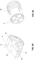
- the distributor drum (38) comprises a drum (8) and a product distributor (11) attached to one another.
- An example of a product distributor (11) has been depicted in Figure 4C .
- the product distributor (11) is attached (preferably by means of an integral attachment) to the drum (8) and drum cover (10) assembly.
- Figure 4D shows a sectional view of a product distributor (11).
- the feeding conduits (12) are also arranged inside the distributor drum (38) when the drum is a single body such as in the example shown in Figure 5A .
- the distributor drum (38) comprises a drum (8) and a distributor (11)
- the attachment between the distributor (11) and the drum (8) and drum cover (10) assembly is made by means of housing the hollow projection (32) of the drum cover (10) in a first receptacle (33) of the distributor (11).
- This first receptacle (33) is arranged in the center of the distributor (11) and in correspondence therewith there is a second receptacle (34), which projects in the opposite direction and is intended for receiving a protrusion (35) of a product selection wheel (13) (in which a key (26) is arranged).
- the inside of the protrusion (35) of the product selection wheel is hollow to allow the passage of a central shaft (30) of a movable casing (14) as will be described below.
- the distributor (11) or the distributor drum (38) preferably comprise sealing gaskets between different feeding bands, that is, between sections of the distributor (11) in which the outlets (25) of the feeding conduits (12) are located which, in a possible embodiment, are arranged radially. There may also be a sealing gasket between the drum (8) and the distributor (11).
- Figure 5B depicts another possible embodiment of the distributor drum (38) in which it comprises a plurality of combinable parts (5), wherein each of them comprises a cavity (9) and the corresponding feeding conduit (12).
- the combinable parts (5) are attached to one another, to the drum cover (10), and to the product selection wheel (13) and are housed in the fixed casing (17).
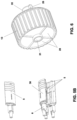
- Figure 6 shows the product selection wheel (13) of the rotary movement assembly (3).
- the distributor drum (38) When it is assembled in the sprayer, it is linked to the distributor drum (38) by means of the protrusion (35) which is housed in the second receptacle (34) of the distributor drum (38). Therefore, upon actuating the rotation of said product selection wheel (13), the entire rotary movable assembly (3) is caused to rotate.
- the unlocking movement assembly (4) shown in an exploded view in Figure 9 , is configured to move axially in the direction of the guide shaft (19) of the sprayer (1) and allows movement of part of the movable equipment (2) out of the outer casing (23), such that the product selection wheel (13) is accessible to the user.
- the unlocking movement assembly (4) comprises a movable casing (14) inside which the product selection wheel (13) and at least part of the distributor drum (38) are housed and inside which they can rotate.
- Figures 7A-B show perspective and sectional views of the movable casing (14).
- the movable casing (14) comprises a first lower and/or side opening (27) that allows the user to access the product selection wheel (13).
- the wheel (13) may comprise, on its rear face, identification labels (28) for identifying the type of product in each compartment in order to make it easier for the user to select the desired product.
- the movable casing (14) comprises a window-like second opening (29) which shows the product identification label (28).
- the movable casing (14) also comprises a central shaft (30) which is intended for being housed inside a through hole (31) of the wheel (13) such that the wheel (13) can rotate about said central shaft (30) but is restricted from moving in the radial direction.
- the restriction of the movement of the wheel (13) in the axial direction with respect to the central shaft (30) is achieved by means of the integral attachment with the distributor drum (38) when the entire movable equipment (2) is assembled.
- the movable casing (14) has a locking groove (36), preferably in its lower area, intended for receiving a projection of a locking button (22) which allows or prevents the axial movement of said movable casing (14) as will be described below.
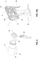
- FIGS 8A-B depict the feeding tube connections (15) which are configured for attaching the compartments with the outlets (25) of the corresponding feeding conduits (12).
- Fixed equipment (16) comprising a fixed casing (17) with a fixed casing cover (18) and the guide shaft (19) about which the movement assembly (3) rotates and along which the unlocking movement assembly (4) moves is also part of the sprayer (1) of the invention.
- the fixed equipment (16) comprises a trigger (20) with which the sprayer is actuated.
- the fixed equipment (16) may also comprise a wheel output spring (21) and a locking button (22). These elements of the fixed equipment (16) can be seen in Figure 9 .
- the trigger (20) to perform a pivoting movement about a pin whereby it is linked to the fixed casing cover (18).
- the wheel output spring (21) is arranged, in one embodiment, between the guide shaft (19) and the hollow projection (32) of the drum cover (10), housed in said hollow projection (32).
- the fixed equipment (16) preferably comprises a locking button (22) that is configured for blocking the axial movement of the unlocking movement assembly (4) with respect to the fixed body (16) when it is partially housed in the locking groove of the movable casing (14).
- the fixed casing (17) also comprises a passage groove (37) for the section of the locking button (22) which is housed, in the locking position, in the locking groove (36) of the movable casing (14).
- the locking button (22) comprises an actuating part (39) which is the one that is actuated by the user, and a second fixing part (40), attached to the actuating part (39) and which is the one that is housed in the locking groove (36).
- the fixing part (4) is assembled on a spring.
- Figure 10A depicts a sectional view of the sprayer (1) with the movable equipment (2) and the fixed equipment (16) assembled. All the elements of the rotary movement assembly (3) and the unlocking movement assembly (4) can also be seen.
- Figure 10B depicts a similar view, but in this case the outer casing (23) of the sprayer (1) is shown in a sectional view, whereas the movable equipment (2) and the fixed equipment (16) are depicted as a whole, without being sectioned.
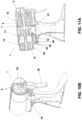
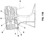
- Figure 11A depicts a sectional view of the sprayer (1) in an unlocked position.
- the locking button (22) is completely outside the locking groove (36) of the movable casing (14) and this has been partially moved towards the outside of the fixed casing (17) and of the outer casing (23). More specifically, the fixing part (40) of the locking button (22) is in the lowest possible position, outside the locking groove (36).
- the first opening (27) remains outside the outer casing (23), allowing the user to access the product selection wheel (13) in order to be able to turn it until selecting the desired product for spraying.
- the locking button (22) preferably comprises springs that exert a thrust force which forces the movement of the fixing part (40) towards the locking groove (36).
- the locking position is shown in Figure 11B .
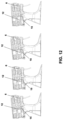
- Figure 12 depicts the different possible locking positions corresponding to the different product selection options.
- the sprayer (1) comprises a plurality of safety elements which prevent the components from breaking and guarantee proper positioning of the spray nozzles (6).
- the sprayer (1) may comprise a plurality of alignment grooves both in the movable equipment (2) and in the fixed equipment (16) such that the unlocking movement assembly (4) (after having selected the product) is always positioned correctly inside the fixed casing (17) when being pushed.
- the device can also comprise a spherical seat which allows a step-by-step product change to be performed as a result of the distributor drum (38) comprising a plurality of spherical seats (preferably "n” spherical seats, wherein "n” is the number of compartments) that are radially aligned in an equidistant manner.
- the device comprises, in the feeding tube connections (15), a spring with a metal sphere acting such that, when turning the product selection wheel (13), the spring yields and the metal sphere fits into the seat, guaranteeing the correct position of the assembly for the selected product.
- the fixed equipment (16) also has two end-of-travel limits which guarantee the correct position of the rotary movement assembly (3) both when it is locked to perform spraying and when it has been unlocked to allow product selection.
- the sprayer (1) may comprise a reinforcement spring linked to the trigger (20), the purpose of which is to facilitate the return of the trigger (20) when it is actuated by a user. If not present, all the return force of the trigger (20) would fall directly on the spring of the piston of the corresponding metering system (7).
Landscapes
- Containers And Packaging Bodies Having A Special Means To Remove Contents (AREA)
- Agricultural Chemicals And Associated Chemicals (AREA)
Claims (17)
- Mehrkammer-Sprühvorrichtung mit einem Hauptkörper, der ein äußeres Gehäuse (23) umfasst und eine Vielzahl von Kammern aufnimmt, die zum Aufnehmen zu versprühender Produkte bestimmt sind, dadurch gekennzeichnet, dass sie in dem Hauptkörper umfasst:- eine bewegliche Einrichtung (2), die ihrerseits umfasst:- eine Drehbewegungs-Baugruppe (3), die so ausgeführt ist, dass sie sich um eine Führungswelle (19) der Sprühvorrichtung (1) herum dreht, und die umfasst:- eine Vielzahl von Düsen (6), die zum Versprühen der Produkte in den Kammern ausgeführt sind;- eine Verteilertrommel (38) mit Hohlräumen (9), in denen Dosiersysteme (7) in Entsprechung zu den Düsen (6) aufgenommen sind, und die eine Vielzahl von Zuführleitungen (12) darin umfasst, von denen jede mit einem der Hohlräume (9) und mit einem Auslass (25) verbunden ist, über den sie mit einem Zuführrohr-Anschluss (15) verbunden sind, über den die in der entsprechenden Kammer aufgenommene Flüssigkeit abgegeben wird;- eine Trommelabdeckung (10), die zum Anbringen an der Verteilertrommel (38) ausgeführt ist;- ein Produkt-Auswahlrad (13), das mit der Verteilertrommel (38) so verbunden ist, dass durch Drehbetätigung des Produkt-Auswahlrades (13) die Drehbewegungs-Baugruppe (3) in Drehung versetzt wird;- eine Entriegelungsbewegungs-Baugruppe (4), die so ausgeführt ist, dass sie die Drehbewegung der Drehbewegungs-Baugruppe (3) zulässt oder verhindert;- eine stationäre Einrichtung (16), die umfasst:- ein stationäres Gehäuse (17) mit einer Abdeckung (18) des stationären Gehäuses und der Führungswelle (19), um die sich die Drehbewegungs-Baugruppe (3) dreht und entlang der sich die Entriegelungsbewegungs-Baugruppe (4) bewegt;- einen Auslöser (20).
- Mehrkammer-Sprühvorrichtung nach Anspruch 1, wobei die Verteilertrommel (38) eine Trommel (8) umfasst, in der sich die Hohlräume (9) befinden, und eine Produkt-Verteilungseinrichtung (11) umfasst, in der sich die Zuführleitungen (12) befinden, und die Trommel (8) und die Produkt-Verteilungseinrichtung (11) aneinander angebracht sind.
- Mehrkammer-Sprühvorrichtung nach Anspruch 1, wobei die Verteilertrommel (38) eine Vielzahl kombinierbarer Teile (5) umfasst, von denen jedes einen Hohlraum (9) sowie die entsprechende Zuführleitung (12) umfasst, und die kombinierbaren Teile (5) aneinander sowie an der Trommelabdeckung (10) und dem Produkt-Auswahlrad (13) angebracht bleiben und in dem stationären Gehäuse (17) aufgenommen werden.
- Mehrkammer-Sprühvorrichtung nach einem der vorangehenden Ansprüche, wobei die Entriegelungsbewegungs-Baugruppe (4) umfasst:- ein bewegliches Gehäuse (14), in dem das Produkt-Auswahlrad (13) und die Produkt-Verteilungseinrichtung (11) aufgenommen sind und in dem sie sich drehen können, wobei das bewegliche Gehäuse (14) eine Verriegelungsnut (36) umfasst;- die Zuführrohr-Anschlüsse (15), die jede Kammer mit der entsprechenden Zuführleitung (12) verbinden.
- Mehrkammer-Sprühvorrichtung nach einem der vorangehenden Ansprüche, wobei die stationäre Einrichtung (16) des Weiteren eine Ausgaberad-Feder (21) umfasst, die zwischen der Führungswelle (19) und dem hohlen Vorsprung (32) der Trommelabdeckung (10) angeordnet und in dem hohlen Vorsprung (32) aufgenommen ist.
- Mehrkammer-Sprühvorrichtung nach Anspruch 4, die einen Verriegelungsknopf (22) umfasst, der so ausgeführt ist, dass er die axiale Bewegung der Entriegelungsbewegungs-Baugruppe (4) in Bezug auf die stationäre Einrichtung (16) blockiert, wenn er teilweise in der Verriegelungsnut (36) des beweglichen Gehäuses (14) aufgenommen ist.
- Mehrkammer-Sprühvorrichtung nach einem der vorangehenden Ansprüche, wobei der Auslöser (20) eine Schwenkbewegung um einen Bolzen herum ausführt, über den er mit der Abdeckung des stationären Gehäuses (18) verbunden ist.
- Mehrkammer-Sprühvorrichtung nach einem der vorangehenden Ansprüche, wobei die Zuführleitungen (12) eine L-förmige Konfiguration haben und der längste Abschnitt von der Position eines Zuführrohr-Anschlusses (15) abhängt, über den die in der entsprechenden Kammer enthaltene Flüssigkeit abgegeben wird.
- Mehrkammer-Sprühvorrichtung nach Anspruch 8, wobei der kürzeste Abschnitt der L-förmigen Zuführleitungen (12) in allen Zuführleitungen (12) gleich ist.
- Mehrkammer-Sprühvorrichtung nach Anspruch 4, wobei das bewegliche Gehäuse (14) eine erste, untere und/oder seitliche Öffnung (27) umfasst, die dem Benutzer Zugang zu dem Produkt-Auswahlrad (13) ermöglicht.
- Mehrkammer-Sprühvorrichtung nach Anspruch 10, wobei das bewegliche Gehäuse (14) eine zweite, fensterartige Öffnung (29) umfasst, die mit der Position wenigstens eines Produktkennungs-Etiketts (18) übereinstimmt, das an einer Rückseite des Produkt-Auswahlrades (13) angeordnet ist.
- Mehrkammer-Sprühvorrichtung nach Anspruch 4, wobei das bewegliche Gehäuse (14) eine mittlere Welle (30) umfasst, die zur Aufnahme im Inneren eines Durchgangslochs (31) des Produkt-Auswahlrades (13) bestimmt ist, so dass sich das Produkt-Auswahlrad (13) mit einer eingeschränkten radialen Bewegung um die mittlere Welle (30) herum drehen kann, und wobei die Einschränkung der axialen Bewegung des Produkt-Auswahlrades (13) in der mittleren Welle (30) des beweglichen Gehäuses (14) mittels einer integralen Anbringung mit der Verteilertrommel (38) beim Montieren der gesamten beweglichen Einrichtung (2) eingeschränkt wird.
- Mehrkammer-Sprühvorrichtung nach Anspruch 6, wobei das stationäre Gehäuse (17) eine Durchlassnut (37) für denjenigen Abschnitt des Verriegelungsknopfes (22) umfasst, der in der Verriegelungsposition in der Verriegelungsnut (36) des beweglichen Gehäuses (14) aufgenommen ist.
- Mehrkammer-Sprühvorrichtung nach Anspruch 6, wobei der Verriegelungsknopf (22) Federn umfasst, die eine Schubkraft ausüben, durch die seine Bewegung in Richtung der Verriegelungsnut (36) erzwungen wird.
- Mehrkammer-Sprühvorrichtung nach einem der vorangehenden Ansprüche, die eine Vielzahl von Ausrichtnuten sowohl in der beweglichen Einrichtung (2) als auch in der stationären Einrichtung (16) umfasst, die so ausgeführt sind, dass sie das korrekte Positionieren der Entriegelungsbewegungs-Baugruppe (4) innerhalb des stationären Gehäuses (17) gewährleisten.
- Mehrkammer-Sprühvorrichtung nach einem der vorangehenden Ansprüche, wobei die Verteilertrommel (38) eine Vielzahl radial ausgerichteter kugelförmiger Aufnahmen umfasst und Federn mit einer Metallkugel in den Zuführrohr-Anschlüssen (15) umfasst, die so wirken, dass beim Drehen des Produkt-Auswahlrades (13) die Feder nachgibt und die Metallkugel mit der kugelförmigen Aufnahme der entsprechenden Verteilertrommel (38) in Passung kommt.
- Mehrkammer-Sprühvorrichtung nach einem der vorangehenden Ansprüche, die eine mit dem Auslöser (20) verbundene Verstärkungsfeder umfasst, die so ausgeführt ist, dass sie die Rückstellbewegung des Auslösers (20) beim Betätigen durch einen Benutzer ermöglicht
Applications Claiming Priority (1)
| Application Number | Priority Date | Filing Date | Title |
|---|---|---|---|
| ES202131094A ES2954131B2 (es) | 2021-11-24 | 2021-11-24 | Pulverizador multicompartimento |
Publications (3)
| Publication Number | Publication Date |
|---|---|
| EP4186599A1 EP4186599A1 (de) | 2023-05-31 |
| EP4186599B1 true EP4186599B1 (de) | 2024-06-12 |
| EP4186599C0 EP4186599C0 (de) | 2024-06-12 |
Family
ID=84329555
Family Applications (1)
| Application Number | Title | Priority Date | Filing Date |
|---|---|---|---|
| EP22205763.0A Active EP4186599B1 (de) | 2021-11-24 | 2022-11-07 | Mehrkammerzerstäuber |
Country Status (5)
| Country | Link |
|---|---|
| US (1) | US12427534B2 (de) |
| EP (1) | EP4186599B1 (de) |
| CN (1) | CN116159684A (de) |
| ES (2) | ES2954131B2 (de) |
| PL (1) | PL4186599T3 (de) |
Family Cites Families (7)
| Publication number | Priority date | Publication date | Assignee | Title |
|---|---|---|---|---|
| BE546389A (de) * | ||||
| US912106A (en) | 1908-03-28 | 1909-02-09 | Edwin J Frazier | Multiple-fluid sprayer. |
| US3298611A (en) | 1965-04-05 | 1967-01-17 | Marraffino | Spray head with rotatable selector |
| IT1264726B1 (it) * | 1993-10-29 | 1996-10-04 | C A M P I Centro Applic Modern | Pistola erogatrice di liquidi ad ugelli multipli. |
| EP2442913B1 (de) | 2009-06-17 | 2019-03-06 | S.C. Johnson & Son, Inc. | Handvorrichtung zur ausgabe von flüssigkeiten |
| ITBO20120211A1 (it) * | 2012-04-17 | 2013-10-18 | Ndustriali S R L | Erogatore a spruzzo di prodotti liquidi |
| US10946393B2 (en) * | 2017-12-28 | 2021-03-16 | Marene Corona | Multi-nozzle multi-container fluid spray device |
-
2021
- 2021-11-24 ES ES202131094A patent/ES2954131B2/es active Active
-
2022
- 2022-11-07 ES ES22205763T patent/ES2982790T3/es active Active
- 2022-11-07 PL PL22205763.0T patent/PL4186599T3/pl unknown
- 2022-11-07 EP EP22205763.0A patent/EP4186599B1/de active Active
- 2022-11-22 US US17/992,178 patent/US12427534B2/en active Active
- 2022-11-24 CN CN202211481155.2A patent/CN116159684A/zh active Pending
Also Published As
| Publication number | Publication date |
|---|---|
| ES2982790T3 (es) | 2024-10-17 |
| ES2954131A1 (es) | 2023-11-20 |
| ES2954131B2 (es) | 2025-11-28 |
| PL4186599T3 (pl) | 2024-09-16 |
| US20230158530A1 (en) | 2023-05-25 |
| EP4186599A1 (de) | 2023-05-31 |
| CN116159684A (zh) | 2023-05-26 |
| EP4186599C0 (de) | 2024-06-12 |
| US12427534B2 (en) | 2025-09-30 |
Similar Documents
| Publication | Publication Date | Title |
|---|---|---|
| US5289946A (en) | Dispenser for media | |
| US7857174B2 (en) | Fluid dispenser | |
| US5335823A (en) | Dispenser for media | |
| EP1999061B1 (de) | Hebelbetätigter spender mit kindersicherer düse | |
| KR102535435B1 (ko) | 분리 출구 유체 카트리지를 단일-입구 혼합기에 연결하기 위한 어댑터 및 관련 방법 | |
| EP4186599B1 (de) | Mehrkammerzerstäuber | |
| EP1920693B1 (de) | Mechanismus zur Hubeinstellung einer Kolbenpumpe | |
| EP3275553A2 (de) | Nichtwiederfüllendes aerosolventil | |
| US8857671B2 (en) | Device for distributing a fluid product | |
| JP2018079984A (ja) | 異なるスプレーを生成するディスペンサのためのシステムおよび方法 | |
| CN110654670A (zh) | 多储液器分配器 | |
| EP0999897B1 (de) | Sprühpistole mit einer verbesserten dichtung | |
| US3722750A (en) | Aerosol can construction | |
| US6405903B2 (en) | Media dispenser | |
| US4978038A (en) | Aerosol dispenser and valve | |
| EP3710168B1 (de) | Filternde flüssigkeitsabgabevorrichtung | |
| US20200253185A1 (en) | Spray device | |
| US7510100B2 (en) | Dose indicator for a fluid dispenser device | |
| US7275660B2 (en) | Dose indicator for fluid product dispensing device | |
| CA2273974A1 (en) | Manually operated pump dispenser having child-resistant nozzle | |
| US3653551A (en) | Aerosol dispenser valve | |
| US20110168743A1 (en) | Paint can dispenser | |
| KR102882016B1 (ko) | 듀얼 펌프 분배 시스템용 액추에이터 | |
| US20250114805A1 (en) | Multiple nozzle holder for agricultural spray system | |
| US20250367694A1 (en) | Dispenser |
Legal Events
| Date | Code | Title | Description |
|---|---|---|---|
| PUAI | Public reference made under article 153(3) epc to a published international application that has entered the european phase |
Free format text: ORIGINAL CODE: 0009012 |
|
| STAA | Information on the status of an ep patent application or granted ep patent |
Free format text: STATUS: THE APPLICATION HAS BEEN PUBLISHED |
|
| AK | Designated contracting states |
Kind code of ref document: A1 Designated state(s): AL AT BE BG CH CY CZ DE DK EE ES FI FR GB GR HR HU IE IS IT LI LT LU LV MC ME MK MT NL NO PL PT RO RS SE SI SK SM TR |
|
| STAA | Information on the status of an ep patent application or granted ep patent |
Free format text: STATUS: REQUEST FOR EXAMINATION WAS MADE |
|
| 17P | Request for examination filed |
Effective date: 20230929 |
|
| RBV | Designated contracting states (corrected) |
Designated state(s): AL AT BE BG CH CY CZ DE DK EE ES FI FR GB GR HR HU IE IS IT LI LT LU LV MC ME MK MT NL NO PL PT RO RS SE SI SK SM TR |
|
| GRAP | Despatch of communication of intention to grant a patent |
Free format text: ORIGINAL CODE: EPIDOSNIGR1 |
|
| STAA | Information on the status of an ep patent application or granted ep patent |
Free format text: STATUS: GRANT OF PATENT IS INTENDED |
|
| INTG | Intention to grant announced |
Effective date: 20240227 |
|
| GRAS | Grant fee paid |
Free format text: ORIGINAL CODE: EPIDOSNIGR3 |
|
| GRAA | (expected) grant |
Free format text: ORIGINAL CODE: 0009210 |
|
| STAA | Information on the status of an ep patent application or granted ep patent |
Free format text: STATUS: THE PATENT HAS BEEN GRANTED |
|
| AK | Designated contracting states |
Kind code of ref document: B1 Designated state(s): AL AT BE BG CH CY CZ DE DK EE ES FI FR GB GR HR HU IE IS IT LI LT LU LV MC ME MK MT NL NO PL PT RO RS SE SI SK SM TR |
|
| REG | Reference to a national code |
Ref country code: GB Ref legal event code: FG4D |
|
| REG | Reference to a national code |
Ref country code: CH Ref legal event code: EP |
|
| REG | Reference to a national code |
Ref country code: IE Ref legal event code: FG4D |
|
| REG | Reference to a national code |
Ref country code: DE Ref legal event code: R096 Ref document number: 602022003932 Country of ref document: DE |
|
| U01 | Request for unitary effect filed |
Effective date: 20240702 |
|
| U07 | Unitary effect registered |
Designated state(s): AT BE BG DE DK EE FI FR IT LT LU LV MT NL PT RO SE SI Effective date: 20240902 |
|
| PG25 | Lapsed in a contracting state [announced via postgrant information from national office to epo] |
Ref country code: HR Free format text: LAPSE BECAUSE OF FAILURE TO SUBMIT A TRANSLATION OF THE DESCRIPTION OR TO PAY THE FEE WITHIN THE PRESCRIBED TIME-LIMIT Effective date: 20240612 |
|
| PG25 | Lapsed in a contracting state [announced via postgrant information from national office to epo] |
Ref country code: GR Free format text: LAPSE BECAUSE OF FAILURE TO SUBMIT A TRANSLATION OF THE DESCRIPTION OR TO PAY THE FEE WITHIN THE PRESCRIBED TIME-LIMIT Effective date: 20240913 |
|
| REG | Reference to a national code |
Ref country code: ES Ref legal event code: FG2A Ref document number: 2982790 Country of ref document: ES Kind code of ref document: T3 Effective date: 20241017 |
|
| U20 | Renewal fee for the european patent with unitary effect paid |
Year of fee payment: 3 Effective date: 20240917 |
|
| PG25 | Lapsed in a contracting state [announced via postgrant information from national office to epo] |
Ref country code: NO Free format text: LAPSE BECAUSE OF FAILURE TO SUBMIT A TRANSLATION OF THE DESCRIPTION OR TO PAY THE FEE WITHIN THE PRESCRIBED TIME-LIMIT Effective date: 20240912 Ref country code: HR Free format text: LAPSE BECAUSE OF FAILURE TO SUBMIT A TRANSLATION OF THE DESCRIPTION OR TO PAY THE FEE WITHIN THE PRESCRIBED TIME-LIMIT Effective date: 20240612 Ref country code: GR Free format text: LAPSE BECAUSE OF FAILURE TO SUBMIT A TRANSLATION OF THE DESCRIPTION OR TO PAY THE FEE WITHIN THE PRESCRIBED TIME-LIMIT Effective date: 20240913 Ref country code: RS Free format text: LAPSE BECAUSE OF FAILURE TO SUBMIT A TRANSLATION OF THE DESCRIPTION OR TO PAY THE FEE WITHIN THE PRESCRIBED TIME-LIMIT Effective date: 20240912 |
|
| PGFP | Annual fee paid to national office [announced via postgrant information from national office to epo] |
Ref country code: PL Payment date: 20241001 Year of fee payment: 3 |
|
| PG25 | Lapsed in a contracting state [announced via postgrant information from national office to epo] |
Ref country code: IS Free format text: LAPSE BECAUSE OF FAILURE TO SUBMIT A TRANSLATION OF THE DESCRIPTION OR TO PAY THE FEE WITHIN THE PRESCRIBED TIME-LIMIT Effective date: 20241012 |
|
| PG25 | Lapsed in a contracting state [announced via postgrant information from national office to epo] |
Ref country code: CZ Free format text: LAPSE BECAUSE OF FAILURE TO SUBMIT A TRANSLATION OF THE DESCRIPTION OR TO PAY THE FEE WITHIN THE PRESCRIBED TIME-LIMIT Effective date: 20240612 |
|
| PG25 | Lapsed in a contracting state [announced via postgrant information from national office to epo] |
Ref country code: SK Free format text: LAPSE BECAUSE OF FAILURE TO SUBMIT A TRANSLATION OF THE DESCRIPTION OR TO PAY THE FEE WITHIN THE PRESCRIBED TIME-LIMIT Effective date: 20240612 |
|
| PG25 | Lapsed in a contracting state [announced via postgrant information from national office to epo] |
Ref country code: SM Free format text: LAPSE BECAUSE OF FAILURE TO SUBMIT A TRANSLATION OF THE DESCRIPTION OR TO PAY THE FEE WITHIN THE PRESCRIBED TIME-LIMIT Effective date: 20240612 |
|
| PGFP | Annual fee paid to national office [announced via postgrant information from national office to epo] |
Ref country code: ES Payment date: 20241202 Year of fee payment: 3 |
|
| PG25 | Lapsed in a contracting state [announced via postgrant information from national office to epo] |
Ref country code: SM Free format text: LAPSE BECAUSE OF FAILURE TO SUBMIT A TRANSLATION OF THE DESCRIPTION OR TO PAY THE FEE WITHIN THE PRESCRIBED TIME-LIMIT Effective date: 20240612 Ref country code: SK Free format text: LAPSE BECAUSE OF FAILURE TO SUBMIT A TRANSLATION OF THE DESCRIPTION OR TO PAY THE FEE WITHIN THE PRESCRIBED TIME-LIMIT Effective date: 20240612 Ref country code: IS Free format text: LAPSE BECAUSE OF FAILURE TO SUBMIT A TRANSLATION OF THE DESCRIPTION OR TO PAY THE FEE WITHIN THE PRESCRIBED TIME-LIMIT Effective date: 20241012 Ref country code: CZ Free format text: LAPSE BECAUSE OF FAILURE TO SUBMIT A TRANSLATION OF THE DESCRIPTION OR TO PAY THE FEE WITHIN THE PRESCRIBED TIME-LIMIT Effective date: 20240612 |
|
| PLBE | No opposition filed within time limit |
Free format text: ORIGINAL CODE: 0009261 |
|
| STAA | Information on the status of an ep patent application or granted ep patent |
Free format text: STATUS: NO OPPOSITION FILED WITHIN TIME LIMIT |
|
| 26N | No opposition filed |
Effective date: 20250313 |
|
| PG25 | Lapsed in a contracting state [announced via postgrant information from national office to epo] |
Ref country code: MC Free format text: LAPSE BECAUSE OF FAILURE TO SUBMIT A TRANSLATION OF THE DESCRIPTION OR TO PAY THE FEE WITHIN THE PRESCRIBED TIME-LIMIT Effective date: 20240612 |
|
| PG25 | Lapsed in a contracting state [announced via postgrant information from national office to epo] |
Ref country code: IE Free format text: LAPSE BECAUSE OF NON-PAYMENT OF DUE FEES Effective date: 20241107 |
|
| U20 | Renewal fee for the european patent with unitary effect paid |
Year of fee payment: 4 Effective date: 20250924 |