EP4186576B1 - Installation d'échange d'ions pour l'utilisation de procédés d'échange d'ions - Google Patents
Installation d'échange d'ions pour l'utilisation de procédés d'échange d'ions Download PDFInfo
- Publication number
- EP4186576B1 EP4186576B1 EP22206636.7A EP22206636A EP4186576B1 EP 4186576 B1 EP4186576 B1 EP 4186576B1 EP 22206636 A EP22206636 A EP 22206636A EP 4186576 B1 EP4186576 B1 EP 4186576B1
- Authority
- EP
- European Patent Office
- Prior art keywords
- columns
- media
- ion exchanger
- exchanger system
- path
- Prior art date
- Legal status (The legal status is an assumption and is not a legal conclusion. Google has not performed a legal analysis and makes no representation as to the accuracy of the status listed.)
- Active
Links
Images

Classifications
-
- B—PERFORMING OPERATIONS; TRANSPORTING
- B01—PHYSICAL OR CHEMICAL PROCESSES OR APPARATUS IN GENERAL
- B01D—SEPARATION
- B01D15/00—Separating processes involving the treatment of liquids with solid sorbents; Apparatus therefor
- B01D15/08—Selective adsorption, e.g. chromatography
- B01D15/10—Selective adsorption, e.g. chromatography characterised by constructional or operational features
- B01D15/18—Selective adsorption, e.g. chromatography characterised by constructional or operational features relating to flow patterns
- B01D15/1864—Selective adsorption, e.g. chromatography characterised by constructional or operational features relating to flow patterns using two or more columns
- B01D15/1871—Selective adsorption, e.g. chromatography characterised by constructional or operational features relating to flow patterns using two or more columns placed in series
-
- B—PERFORMING OPERATIONS; TRANSPORTING
- B01—PHYSICAL OR CHEMICAL PROCESSES OR APPARATUS IN GENERAL
- B01D—SEPARATION
- B01D15/00—Separating processes involving the treatment of liquids with solid sorbents; Apparatus therefor
- B01D15/08—Selective adsorption, e.g. chromatography
- B01D15/26—Selective adsorption, e.g. chromatography characterised by the separation mechanism
- B01D15/36—Selective adsorption, e.g. chromatography characterised by the separation mechanism involving ionic interaction, e.g. ion-exchange, ion-pair, ion-suppression or ion-exclusion
- B01D15/361—Ion-exchange
-
- B—PERFORMING OPERATIONS; TRANSPORTING
- B01—PHYSICAL OR CHEMICAL PROCESSES OR APPARATUS IN GENERAL
- B01J—CHEMICAL OR PHYSICAL PROCESSES, e.g. CATALYSIS OR COLLOID CHEMISTRY; THEIR RELEVANT APPARATUS
- B01J47/00—Ion-exchange processes in general; Apparatus therefor
- B01J47/02—Column or bed processes
- B01J47/022—Column or bed processes characterised by the construction of the column or container
-
- G—PHYSICS
- G01—MEASURING; TESTING
- G01N—INVESTIGATING OR ANALYSING MATERIALS BY DETERMINING THEIR CHEMICAL OR PHYSICAL PROPERTIES
- G01N30/00—Investigating or analysing materials by separation into components using adsorption, absorption or similar phenomena or using ion-exchange, e.g. chromatography or field flow fractionation
- G01N30/96—Investigating or analysing materials by separation into components using adsorption, absorption or similar phenomena or using ion-exchange, e.g. chromatography or field flow fractionation using ion-exchange
-
- B—PERFORMING OPERATIONS; TRANSPORTING
- B01—PHYSICAL OR CHEMICAL PROCESSES OR APPARATUS IN GENERAL
- B01D—SEPARATION
- B01D15/00—Separating processes involving the treatment of liquids with solid sorbents; Apparatus therefor
- B01D15/08—Selective adsorption, e.g. chromatography
- B01D15/10—Selective adsorption, e.g. chromatography characterised by constructional or operational features
- B01D15/18—Selective adsorption, e.g. chromatography characterised by constructional or operational features relating to flow patterns
- B01D15/1814—Recycling of the fraction to be distributed
- B01D15/1821—Simulated moving beds
- B01D15/1842—Simulated moving beds characterised by apparatus features
-
- G—PHYSICS
- G01—MEASURING; TESTING
- G01N—INVESTIGATING OR ANALYSING MATERIALS BY DETERMINING THEIR CHEMICAL OR PHYSICAL PROPERTIES
- G01N30/00—Investigating or analysing materials by separation into components using adsorption, absorption or similar phenomena or using ion-exchange, e.g. chromatography or field flow fractionation
- G01N30/02—Column chromatography
- G01N30/26—Conditioning of the fluid carrier; Flow patterns
- G01N30/38—Flow patterns
- G01N30/46—Flow patterns using more than one column
- G01N30/468—Flow patterns using more than one column involving switching between different column configurations
Definitions
- the present invention relates to an ion exchange system for use in ion exchange processes, in particular for changing the material composition of a solution, comprising a plurality of columns through which fluid can flow, each column having a first inlet/outlet end and a second inlet/outlet end, and comprising a plurality of media paths, each inlet/outlet end being connectable to at least two media paths, each media path having one or more inlets and the media paths having one or more outlets.
- WO 2006/131286 A1 A device for the chromatographic separation of mixtures is known, which comprises a plurality of chromatographic columns connected in series, wherein the columns can be coupled to a plurality of media paths. Similar devices are also known from the publications CN 111 249 770 A , WO 2012/078677 A2 or EP 3 702 775 A1 .
- Ion exchange processes are used to change the composition of solutions. Typically, ions of one type are exchanged for ions of another type while the solution flows through the ion exchanger in the form of a column.
- a typical process is as follows:
- the functional groups of the ion exchanger are loaded with type 1 ions (e.g., H+ ions during the regeneration of a cation exchanger with an acid).
- the regeneration solution is displaced with demineralized water (DI water).
- DI water demineralized water
- the volume of regeneration solution remaining in the column at the end of step 1 is drained from the column first until the concentration of the solution then drops abruptly (sometimes called “sweetening").
- a sufficiently reduced product concentration typically marks the end of the displacement process.
- the commonly used displacement flow rate is 0.3 to 0.5 BV.
- the regenerant itself often cannot be present in the product that subsequently flows through the column. Therefore, the concentration of the regenerant is washed down with demineralized water, usually to a level that allows for sufficient purity of the final product.
- the required demineralized water flow rate varies and depends on the purity requirements. It is often between 1.5 and 5 BV.
- the reactant solution is added to the column.
- the column's previous contents essentially the wash water after regeneration, drain off (sometimes called “sweetening").
- the loading is typically divided into:
- Step 4a Sweetening / Concentrating
- This first stage of reactant loading pushes only water out of the column.
- the liquid throughput in this step is usually about 0.3 to 0.5 BV.
- the column is loaded with reactant solution at the inlet, but it is not yet producing any product at the outlet.
- the throughput of the following The production step depends on the capacity of the ion exchanger and the concentration of the ion species to be exchanged in the reactant.
- typical loading throughputs are in the range of 1 to 2 BV. They are therefore in the same order of magnitude as the regeneration and displacement throughputs, which is essential for the process types described here.
- Step 4c Sweetening / Concentration
- the concentration of the undesired ion species in the column effluent slowly increases (breakthrough situation). Production must therefore be stopped at this point to avoid deteriorating the quality of the effluent product.
- the column still contains reactant solution with a significantly higher concentration of the undesired ion species present in the reactant. This reactant holdup in the column (typically 0.3 to 0.5 BV) must not be passed into the product, but it should also not be lost. This holdup is therefore typically returned to the reactant during concentration.
- Step 1 is then also divided into sub-steps 1a to 1c, depending on the specific design of the ion exchange process.
- the number of steps in the overall process is thus often between 4 and 10, rarely fewer, but often more.
- a crossing realized by means of four valves connected to one another via an H-piping, by means of which any number of adjacent columns can be operated in series, wherein by means of the crossing the first inlet/outlet ends and the second inlet/outlet ends (3) of two adjacent columns can be coupled to one another as desired to provide a fluid path.
- the invention thus relates to a novel technology for ion exchange processes, which enables short-cycle carousel processes ("Merry-Go-Round" or MGR processes), which, due to a recipe sequence control within each individual product path and selectable column assignments to the parallel running individual recipes, offer a significantly increased adaptability to, for example, varying feed concentrations as well as the variable flow direction through each column in each step.
- MGR processes short-cycle carousel processes
- the device according to the invention is a clever combination of several columns, whereby (as with the SMB) temporal parallelisms can be used, since a certain number of the available columns can be flexibly assigned to the loading, another number to the regeneration and, if necessary, another group to the laundry (3 media paths for loading, regeneration and laundry, for example).
- valve circuits also offers the possibility of freely selecting the flow direction through the column for each individual step and sub-step at any time via software – even after the system has been commissioned. This is fundamentally no longer the case with existing systems, as two examples from the prior art demonstrate.
- a predetermined number of columns can be provided as loading columns (designated by the variable L).
- the loading columns can be configured so that they can be operated in series.
- the number of loading columns can be smaller than the total number of columns.
- a predetermined number of columns can be designated as regeneration columns (designated by the variable R). It can be provided that the number of Regeneration columns is less than or equal to the difference between the total number of columns and the number of loading columns.
- a predetermined number of columns can be designated as laundry columns (designated by the variable W).
- the number of laundry columns can be between 1 and 2.
- the columns can be rotated logically via valve switching (not physically, as with SMB).
- the ion exchange system can be controlled in such a way that, within each individual logical rotation step of the column sequence, several sub-steps take place sequentially.
- the control can be implemented via a recipe controller. It can be provided that the use of several media sequentially is possible during a single rotation step.
- the ion exchange system can be designed in such a way that each of the several media can be made available once for each path via an individual valve.
- the ion exchange system or carousel system can have between 2 and 3 (or more; designated P) media paths running through the system. It can be provided that each of the multiple media can be fed to each media path independently of one another. The flow rate of each media path can be individually adjusted. This means that all media paths can have a different flow rate and operate simultaneously.
- a specific column group can be selected through which the media path is to flow.
- a specific outlet from several outlets of the ion exchange system can be selected, whereby it is also possible to switch between the individual outlets sequentially within a rotation step.
- the ion exchange system or carousel system can therefore have a fine structure of individual sub-steps (sub-recipes), which, for example, run via a recipe control within each rotation step.
- a sub-recipe i.e., P sub-recipes
- the rotation step can then rotate the carousel one logical position at all positions. This rotation can be configured to run only in the software, not, as with the SMB, an actual mechanical rotation. Then the fine-structure recipes run again.
- the number of column positions required to run through, for example, 6 to 9 (or more) process steps is no longer 6 to 9 (or more) as with the SMB process, but only the aforementioned 3 to 5.
- the total time of the partial recipe steps within each partial recipe sequence is similar or identical for each path.
- one of the paths e.g., the loading path
- the path selected as the master can execute the up-concentration and down-concentration steps and the intermediate loading steps using a fine-structure recipe.
- the first column (fully loaded working position) can be transferred to the regeneration path, followed by a rotation step, and the next group of L-shaped columns can be loaded.
- this rotation step transfers a single column from the wash to the loading chain at the end, and a single column from the front position to the regeneration, regardless of how many columns are in the loading chain.
- a third path can simply be added (P then becomes, for example, 3) and, if necessary, the number of columns C can be increased.
- the core of the invention is therefore the provision of an RI scheme (piping and instrumentation scheme) where the valves and flow controllers can be controlled and locked with a novel multiple recipe control according to a goal-oriented master-slave concept.
- RI scheme piping and instrumentation scheme
- MGR Merry-Go-Round process
- the SMB technology can therefore be seen as the specialization of the MGR process for very short loading times of a similar order of magnitude to the regeneration time, which consequently required very rigid process sequences, a common cycle time for all individual steps, a high number of individual columns and a very complicated and vulnerable valve technology.
- regenerant costs play a very important role in all short-cycle ion exchange processes. It is therefore important to minimize these.
- the state of the art in this area is the method of fractional regeneration.
- one or more fraction tanks are used to temporarily store regenerant effluents.
- the second half of the regenerant effluent (with a still significant portion of unused regenerant) is passed through the column as the first fraction during the next regeneration, and fresh regenerant solution is only used during the second half of the regeneration.
- one tank can almost halve regenerant consumption.
- the regenerant consumption can theoretically be reduced to 1/F. Due to the reduced regenerating effect of the recycled fractions, this saving factor is usually not achieved.
- a limitation of this method is the cost and space required for the additional tanks.
- the feed to a regenerating fractionation tank initially has less regenerating effect than later. However, this is mixed in the fraction tank, so that only an average regeneration effect is achieved in the recycled fraction.
- the potential for optimal regeneration in countercurrent with a constantly increasing residual acid concentration can only be utilized with a large number of fraction tanks.
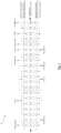
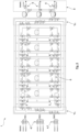
- Fig. 3 shows an RI flow diagram of an embodiment of the ion exchange system according to the invention.
- the ion exchange system 1 has a plurality of columns C through which fluid can flow, each column having a first inlet/outlet end 2 and a second inlet/outlet end 3 on its top and bottom. Furthermore, a plurality of media paths P are provided, each inlet/outlet end 2, 3 being coupleable to each of the media paths P via valves Y NNN provided for this purpose.
- Each media path P has a separate inlet 4 and a separate outlet.
- Each of the inlets 4 of the media paths P has an inlet switch 7, so that a plurality of different media can be fed into each media path P separately or in a mixed ratio.
- medium 1 and medium 2 can be fed in via the first medium path P1, medium 1, medium 2 and medium 3 via the second medium path P2 and medium 2 and medium 3 via the third medium path.
- a crossing 6 which is implemented by means of four valves Yx11, Yx12, Yx13, Yx14 which are connected to one another via an H-piping, and by means of which any number of adjacent columns C can be operated in series.
- the first inlet/outlet ends 2 and the second inlet/outlet ends 3 are each connected to each of the media paths P via separate pipe connections and can be coupled to them via separate valves Yx15, Yx16, Yx17, Yx18, Yx19, Yx20.
- first inlet/outlet ends 2 and the second inlet/outlet ends 3 of two adjacent columns Ci and Ci+1 can be coupled to one another in any way to provide a fluid path, so that, for example, the first inlet/outlet end 2 of a first column C1 can be coupled to the first inlet/outlet end 2 or the second inlet/outlet end 3 of a second column C2, or even to the second inlet/outlet end 3 of the first column C1.
- the second inlet/outlet end 3 of a first column C1 can be coupled to the first inlet/outlet end 2 or the second inlet/outlet end 3 of a second column C2.
- the ion exchange system can have an interlocking circuit which prevents each of the plurality of columns C is used by more than one path P at the same time.
- the ion exchange system 1 can also be controlled in such a way that, when columns C are operated in series, the intersection 6 located between them can only be used by one media path P at a time.
- Each of the media paths can have its own flow control so that all media paths P can be operated in parallel.
- the valves Y NNN are each designed as discrete 2/2-way valves.
- Each of the media paths P can be operated in two different directions so that each medium can be guided through the columns C in an upflow or downflow manner.
- two directional valves Y R are adjacent to each inlet 4 and downstream thereof and to each outlet 4 and upstream thereof in opposite directions of the respective media path P, via which directional valves the respective medium can be guided in different flow directions via the media path P.
- the flow in each of the media paths (P) can be individually adjusted by means of a flow control.
- a drain intersection 8 is provided between the drains 5, via which the guided media can be at least partially transferred between the drains 5.
- the product drain and the regenerate drain each have corresponding valves Y9x1, Y9x2, etc., to divert the incoming medium to the other product/regenerate drain or to the wastewater drain.
- the three marked medium paths P each have their own flow control, allowing them to be operated in parallel.
- a software interlock prevents columns C from being used by more than one path P.
- the control can be configured, but not necessarily, so that the subordinate paths have priority (washing in path P3 has priority over regeneration in path P2, and this has priority over loading in path P1).
- the control can, of course, also provide a different priority order for the individual paths P.
- Each path has an input switch 7, so that each connected medium 1-2 or 1-3 can be used in the partial recipe of the respective path P. This clearly shows that only a single valve would need to be added to offer a new medium to a path P. This could even be easily done after commissioning of ion exchange system 1, if necessary.
- the group of four directional valves per path (Y7x1, Y7x2, Y7x3, Y7x4) allows the respective medium to be directed upstream or downstream through the columns. This requires only a software input in the partial recipe; no re-piping is required.
- the system according to the invention possesses precisely the versatile properties mentioned above, which are advantageous and innovative compared to the SMB process.
- Table 1 shows an example of a loading sub-recipe, which is executed sequentially on all conceivable column sequences with two columns in series. It is designed to act as a master recipe, taking control of the entire system and triggering the regeneration sub-recipes at the appropriate time (last column).
- This sub-recipe already includes the sweetening and desweetening processes.
- ⁇ i>Table 1 Example loading sub-recipe ⁇ /i> Entrance Direction Columns Exit Flow End when reference max. avg. then to the reg. reactant Upflow 1->2 AW 2 BV/h LF3 > 2000 ⁇ S/cm 0.5 reactant Upflow 1->2 product 2 BV/h after max. throughput 1.5 Water Upflow 1->2 product 2 BV/h after max.
- the loading recipe thus consists of 15 steps, which run sequentially at five rotation positions. This is significantly fewer than with the state-of-the-art SMB.
- Table 2 shows the sub-recipe for a typical regeneration, which then runs parallel to the loading process, as a separate media path with media selection, flow control, and output selection is available for regeneration.
- the total duration of this sub-recipe corresponds to the duration of three steps in the loading recipe: ⁇ i>Table 2
- Example regeneration recipe ⁇ /i> Entrance Direction Columns Exit Flow End when reference max. avg. then to the W.
- the "master" determines which columns C are to be used by this regeneration recipe, as this knows the current use of the individual columns C.
- a fifth column C5 and a wash recipe are added, which has a maximum of the time of the regeneration recipe available.
- This wash recipe shown in Table 3, which then runs parallel to loading and regeneration (since a separate media path with media selection, flow control, and output selection is also available for this), is initiated at the end of the regeneration recipe, and the column C (or column sequence) to be washed is also transferred from the regeneration recipe to the wash recipe. This is the column C that was at the front in the last regeneration step. If the regeneration has run from S5 to S1, for example, S5 is washed next. ⁇ i>Table 3
- Example washing recipe ⁇ /i> Entrance Direction Columns Exit Flow End when reference max. diameter Water Downstream S(i) Wastewater. 2.50 BV/h LF ⁇ 1000 ⁇ S/cm 3 Rotation 1.20 h
- the gray fields i.e. the first three lines in column 2 and the first 6 lines in column 3, are not used when the process starts up, but are run during rolling operation. It can be seen how the loading recipe takes on the master function, while the regeneration recipe only runs for 3 lines and is then restarted with a new column combination. The same applies to the wash. It can also be seen that no conflicts arise regarding column assignments in the process. In summary, this example shows that for a total of 7 process steps, only 5 columns are necessary. Although this is simplified, it illustrates the essence of the invention. It can also be seen that, in principle, the flow direction could be changed in each partial recipe step, which would only require a slightly different valve circuit. It can also be seen that each partial recipe step has its own specification for the flow and maximum throughput, meaning that even different flows can be used within the partial recipes.
- the rotation time T Rotation is also specified. Both the regeneration and wash recipes run for a maximum of 1.2 hours, while the loading is slightly longer at 1.25 hours. If the regeneration recipe or the wash recipe runs for a slightly shorter time, for example, because the displacements are faster than estimated, their The partial recipe duration can therefore be slightly shorter than 1.2 hours, and the washed column will be available at the end somewhat earlier than required. This effectively avoids the rigidity of the SMB process. If the situation is reversed and a column C required for the loading chain is not yet fully washed, the loading recipe will wait, which is ensured by the software locking.
Landscapes
- Chemical & Material Sciences (AREA)
- Analytical Chemistry (AREA)
- Chemical Kinetics & Catalysis (AREA)
- Life Sciences & Earth Sciences (AREA)
- Physics & Mathematics (AREA)
- Health & Medical Sciences (AREA)
- Organic Chemistry (AREA)
- Biochemistry (AREA)
- General Health & Medical Sciences (AREA)
- General Physics & Mathematics (AREA)
- Immunology (AREA)
- Pathology (AREA)
- Treatment Of Water By Ion Exchange (AREA)
Claims (14)
- Appareil d'échange d'ions (1) destiné à être utilisé dans les procédés d'échange d'ions, en particulier pour modifier la composition matérielle d'une solution,comportant plusieurs colonnes (C) à travers lesquelles le fluide peut circuler, chaque colonne ayant une première extrémité d'entrée/sortie (2) et une deuxième extrémité d'entrée/sortie (3)et avec une pluralité de voies de média (P), où chaque extrémité d'entrée/sortie (2, 3) peut être couplée à au moins deux voies de média (P) ;où chaque chemin de média (P) a une ou plusieurs entrées (4) et les chemins de média (P) ont une ou plusieurs sorties (5),caractérisé en ce qu'un croisement (6) est prévu entre des colonnes adjacentes (C), ce croisement étant réalisé au moyen de quatre vannes (YX11, YX12, YX13, YX14) reliées entre elles par une tuyauterie en H et au moyen desquelles un nombre quelconque de colonnes adjacentes (C) peuvent être exploitées en série, les premières extrémités d'entrée/sortie (2) et les secondes extrémités d'entrée/sortie (3) de deux colonnes voisines (C) pouvant être couplées l'une à l'autre de la manière souhaitée au moyen de l'intersection (6) pour fournir un chemin de fluide.
- installation d'échange d'ions selon la revendication 1, dans laquelle chaque extrémité d'entrée/sortie (2, 3) peut être couplée à chacun des trajets de fluide (P).
- installation d'échange d'ions selon la revendication 1 ou 2, dans laquelle les premières extrémités d'entrée/sortie (2) et les deuxièmes extrémités d'entrée/sortie (3) sont reliées chacune par des raccords de tuyaux séparés à au moins deux des voies de fluide (P), de préférence à chacune des voies de fluide (P), et peuvent être couplées chacune à celles-ci par des vannes séparées (Y).
- Installation d'échange d'ions (1) selon l'une quelconque des revendications précédentes, qui comprend en outre un circuit de verrouillage qui empêche chacune des multiples colonnes (C) d'être utilisée par plus d'un chemin (P) à la fois.
- Installation d'échange d'ions (1) selon l'une des revendications précédentes, qui est en outre commandée de telle sorte que, dans le cas de colonnes (C) fonctionnant en série, le croisement (6) se trouvant entre elles ne peut être utilisé que par un seul chemin de fluide (P) à la fois.
- Installation d'échange d'ions (1) selon l'une des revendications précédentes, qui présente entre trois et cinq, de préférence entre quatre et cinq, colonnes (C) pouvant être traversées par un fluide.
- Installation d'échange d'ions (1) selon l'une des revendications précédentes, qui présente au moins trois voies de fluide (P).
- Installation d'échange d'ions (1) selon l'une des revendications précédentes, dans laquelle au moins l'une des entrées (4) des voies de fluide (P) présente une commutation d'entrée (7), de sorte que pour chaque voie de fluide (P) avec commutation d'entrée (7), une pluralité de fluides différents peuvent être alimentés séparément ou dans un rapport de mélange.
- Installation d'échange d'ions (1) selon l'une des revendications précédentes, dans laquelle chacun des trajets de fluide (P) présente un contrôle de flux propre, de sorte que tous les trajets de fluide (P) peuvent être exploités en parallèle dans le temps.
- Installation d'échange d'ions (1) selon l'une des revendications précédentes, dans laquelle la pluralité de vannes (Y) est conçue comme des vannes discrètes.
- Installation d'échange d'ions (1) selon l'une des revendications précédentes, dans laquelle chacun des trajets de fluide (P) peut être exploité dans deux directions différentes, de sorte que chaque fluide peut être guidé en amont ou en aval à travers les colonnes (C).
- Installation d'échange d'ions (1) selon la revendication 11, dans laquelle deux vannes directionnelles (YR) sont respectivement adjacentes à chaque arrivée (4) et en aval de celle-ci ainsi qu'à chaque sortie (4) et en amont de celle-ci dans des directions opposées du chemin de fluide respectif, par lesquelles le fluide respectif peut être guidé dans différentes directions d'écoulement sur le chemin de fluide (P).
- Installation d'échange d'ions (1) selon l'une des revendications précédentes, qui est conçue de telle sorte que le débit dans chacun des trajets de fluide (P) est réglable individuellement.
- Installation d'échange d'ions (1) selon l'une des revendications précédentes, dans laquelle il est en outre prévu entre les sorties (5) un croisement de sortie (8) par lequel les fluides guidés peuvent être transférés au moins partiellement entre les sorties (5).
Applications Claiming Priority (1)
| Application Number | Priority Date | Filing Date | Title |
|---|---|---|---|
| DE102021130958.1A DE102021130958A1 (de) | 2021-11-25 | 2021-11-25 | Ionenaustauscheranlage zur Verwendung in Ionenaustauschprozessen |
Publications (3)
| Publication Number | Publication Date |
|---|---|
| EP4186576A1 EP4186576A1 (fr) | 2023-05-31 |
| EP4186576B1 true EP4186576B1 (fr) | 2025-06-25 |
| EP4186576C0 EP4186576C0 (fr) | 2025-06-25 |
Family
ID=84331127
Family Applications (1)
| Application Number | Title | Priority Date | Filing Date |
|---|---|---|---|
| EP22206636.7A Active EP4186576B1 (fr) | 2021-11-25 | 2022-11-10 | Installation d'échange d'ions pour l'utilisation de procédés d'échange d'ions |
Country Status (2)
| Country | Link |
|---|---|
| EP (1) | EP4186576B1 (fr) |
| DE (1) | DE102021130958A1 (fr) |
Family Cites Families (5)
| Publication number | Priority date | Publication date | Assignee | Title |
|---|---|---|---|---|
| US20060273013A1 (en) * | 2004-03-01 | 2006-12-07 | Chin Nien-Hwa L | Versatile simulated moving bed systems |
| DE102005026486A1 (de) * | 2005-06-09 | 2006-12-14 | Bayer Technology Services Gmbh | Ein chromatographisches quasi-kontinuierliches Verfahren und entsprechende Vorrichtung zur Trennung von binären und Mehrstoffgemischen |
| US20120091063A1 (en) * | 2009-06-26 | 2012-04-19 | Ge Healthcare Bio-Sciences Ab | Method in a chromatography system |
| JP2013544524A (ja) * | 2010-12-06 | 2013-12-19 | ターポン バイオシステムズ,インコーポレイテッド | 生物学的生成物の連続プロセス法 |
| CN111249770B (zh) * | 2020-04-02 | 2024-07-05 | 张永阔 | 一类生产型连续流层析系统 |
-
2021
- 2021-11-25 DE DE102021130958.1A patent/DE102021130958A1/de active Pending
-
2022
- 2022-11-10 EP EP22206636.7A patent/EP4186576B1/fr active Active
Also Published As
| Publication number | Publication date |
|---|---|
| EP4186576C0 (fr) | 2025-06-25 |
| DE102021130958A1 (de) | 2023-05-25 |
| EP4186576A1 (fr) | 2023-05-31 |
Similar Documents
| Publication | Publication Date | Title |
|---|---|---|
| EP0598249B1 (fr) | Procédé et appareil pour déminéraliser des solutions aqueuses à l'aide de masses échangeuses d'ions | |
| DE69308026T2 (de) | Eine Fluidum Verteilungsvorrichtung, ein similiertes bewegendes Bett und eine kontinuierliche Adsorptionsmethode | |
| DE10332789A1 (de) | Membrananordnung, Elektrodialysevorrichtung und Verfahren zur kontinuierlichen elektrodialytischen Entsalzung | |
| DE1293698B (de) | Verfahren und Vorrichtung zum Enthärten von Wasser | |
| DE3429556A1 (de) | Verfahren zur regelung eines kuenstlichen fliessbettsystems | |
| EP3694623B1 (fr) | Système de filtre | |
| DE102007028116B3 (de) | Mikrofluidiksystem zum Mischen von mindestens zwei Ausgangsstoffen | |
| DE2230714C3 (de) | Vorrichtung zum kontinuierlichen Behandeln von Flüssigkeiten | |
| EP2836465B1 (fr) | Procédé permettant de faire fonctionner une installation de traitement de l'eau | |
| EP1551588A1 (fr) | Dispositif de nettoyage et procede pour nettoyer le gaz de process d'une installation de brasage par fusion | |
| EP4186576A1 (fr) | Installation d'échange d'ions pour l'utilisation de procédés d'échange d'ions | |
| DE4227135C2 (de) | Ventilsystem für eine Ionenaustauscheranlage | |
| EP0462523B1 (fr) | Appareil et procédé pour le traitement de l'eau | |
| DE2439303C2 (de) | Vorrichtung zum Abtrennen von feinverteilten emulgierten und/oder gelösten Stoffen sowie Feststoffen aus Flüssigkeiten | |
| DE2621937A1 (de) | Mehrstufen-expansionsverdampfer | |
| DE2027901B2 (de) | Verfahren zum kontinuierlichen Betrieb und zur Regenerierung einer Ionenaustauschanlage | |
| DE102021103911A1 (de) | Verfahren und Steuereinrichtung zur Steuerung einer Wasserbehandlungsanlage sowie Wasserbehandlungsanlage mit einer Steuereinrichtung | |
| DE102005026486A1 (de) | Ein chromatographisches quasi-kontinuierliches Verfahren und entsprechende Vorrichtung zur Trennung von binären und Mehrstoffgemischen | |
| DE2725895A1 (de) | Verfahren und vorrichtung zum behandeln eines fluids | |
| EP0184773A2 (fr) | Installation d'adoucissement d'eau | |
| DE29512743U1 (de) | Latentwärmespeicher | |
| EP4389250A1 (fr) | Appareil pour la régénération de lits mélangés d'échangeurs d'ions et procédé de régénération associé | |
| EP0187880A1 (fr) | Procédé et appareil pour le traitement de liquides, en particulier pour la deminéralisation de solutions aqueuses | |
| DE102010034966B4 (de) | Ionentauscher | |
| EP0616822B1 (fr) | Procédé d'utilisation d'un adsorbeur et installation pour la réalisation du procédé |
Legal Events
| Date | Code | Title | Description |
|---|---|---|---|
| PUAI | Public reference made under article 153(3) epc to a published international application that has entered the european phase |
Free format text: ORIGINAL CODE: 0009012 |
|
| STAA | Information on the status of an ep patent application or granted ep patent |
Free format text: STATUS: THE APPLICATION HAS BEEN PUBLISHED |
|
| STAA | Information on the status of an ep patent application or granted ep patent |
Free format text: STATUS: REQUEST FOR EXAMINATION WAS MADE |
|
| AK | Designated contracting states |
Kind code of ref document: A1 Designated state(s): AL AT BE BG CH CY CZ DE DK EE ES FI FR GB GR HR HU IE IS IT LI LT LU LV MC ME MK MT NL NO PL PT RO RS SE SI SK SM TR |
|
| 17P | Request for examination filed |
Effective date: 20230511 |
|
| RBV | Designated contracting states (corrected) |
Designated state(s): AL AT BE BG CH CY CZ DE DK EE ES FI FR GB GR HR HU IE IS IT LI LT LU LV MC ME MK MT NL NO PL PT RO RS SE SI SK SM TR |
|
| GRAP | Despatch of communication of intention to grant a patent |
Free format text: ORIGINAL CODE: EPIDOSNIGR1 |
|
| STAA | Information on the status of an ep patent application or granted ep patent |
Free format text: STATUS: GRANT OF PATENT IS INTENDED |
|
| RIC1 | Information provided on ipc code assigned before grant |
Ipc: G01N 30/96 20060101ALI20250408BHEP Ipc: G01N 30/46 20060101ALI20250408BHEP Ipc: B01J 47/00 20170101ALI20250408BHEP Ipc: B01D 15/36 20060101ALI20250408BHEP Ipc: B01D 15/18 20060101AFI20250408BHEP |
|
| GRAS | Grant fee paid |
Free format text: ORIGINAL CODE: EPIDOSNIGR3 |
|
| GRAA | (expected) grant |
Free format text: ORIGINAL CODE: 0009210 |
|
| STAA | Information on the status of an ep patent application or granted ep patent |
Free format text: STATUS: THE PATENT HAS BEEN GRANTED |
|
| INTG | Intention to grant announced |
Effective date: 20250507 |
|
| AK | Designated contracting states |
Kind code of ref document: B1 Designated state(s): AL AT BE BG CH CY CZ DE DK EE ES FI FR GB GR HR HU IE IS IT LI LT LU LV MC ME MK MT NL NO PL PT RO RS SE SI SK SM TR |
|
| REG | Reference to a national code |
Ref country code: GB Ref legal event code: FG4D Free format text: NOT ENGLISH |
|
| REG | Reference to a national code |
Ref country code: CH Ref legal event code: EP |
|
| REG | Reference to a national code |
Ref country code: CH Ref legal event code: EP |
|
| REG | Reference to a national code |
Ref country code: IE Ref legal event code: FG4D Free format text: LANGUAGE OF EP DOCUMENT: GERMAN |
|
| U01 | Request for unitary effect filed |
Effective date: 20250625 |
|
| U07 | Unitary effect registered |
Designated state(s): AT BE BG DE DK EE FI FR IT LT LU LV MT NL PT RO SE SI Effective date: 20250701 |
|
| PG25 | Lapsed in a contracting state [announced via postgrant information from national office to epo] |
Ref country code: GR Free format text: LAPSE BECAUSE OF FAILURE TO SUBMIT A TRANSLATION OF THE DESCRIPTION OR TO PAY THE FEE WITHIN THE PRESCRIBED TIME-LIMIT Effective date: 20250926 Ref country code: NO Free format text: LAPSE BECAUSE OF FAILURE TO SUBMIT A TRANSLATION OF THE DESCRIPTION OR TO PAY THE FEE WITHIN THE PRESCRIBED TIME-LIMIT Effective date: 20250925 |
|
| PG25 | Lapsed in a contracting state [announced via postgrant information from national office to epo] |
Ref country code: HR Free format text: LAPSE BECAUSE OF FAILURE TO SUBMIT A TRANSLATION OF THE DESCRIPTION OR TO PAY THE FEE WITHIN THE PRESCRIBED TIME-LIMIT Effective date: 20250625 |
|
| PG25 | Lapsed in a contracting state [announced via postgrant information from national office to epo] |
Ref country code: RS Free format text: LAPSE BECAUSE OF FAILURE TO SUBMIT A TRANSLATION OF THE DESCRIPTION OR TO PAY THE FEE WITHIN THE PRESCRIBED TIME-LIMIT Effective date: 20250925 |
|
| U20 | Renewal fee for the european patent with unitary effect paid |
Year of fee payment: 4 Effective date: 20251126 |
|
| PG25 | Lapsed in a contracting state [announced via postgrant information from national office to epo] |
Ref country code: IS Free format text: LAPSE BECAUSE OF FAILURE TO SUBMIT A TRANSLATION OF THE DESCRIPTION OR TO PAY THE FEE WITHIN THE PRESCRIBED TIME-LIMIT Effective date: 20251025 |
|
| PG25 | Lapsed in a contracting state [announced via postgrant information from national office to epo] |
Ref country code: SM Free format text: LAPSE BECAUSE OF FAILURE TO SUBMIT A TRANSLATION OF THE DESCRIPTION OR TO PAY THE FEE WITHIN THE PRESCRIBED TIME-LIMIT Effective date: 20250625 |
|
| PG25 | Lapsed in a contracting state [announced via postgrant information from national office to epo] |
Ref country code: CZ Free format text: LAPSE BECAUSE OF FAILURE TO SUBMIT A TRANSLATION OF THE DESCRIPTION OR TO PAY THE FEE WITHIN THE PRESCRIBED TIME-LIMIT Effective date: 20250625 |
|
| PG25 | Lapsed in a contracting state [announced via postgrant information from national office to epo] |
Ref country code: PL Free format text: LAPSE BECAUSE OF FAILURE TO SUBMIT A TRANSLATION OF THE DESCRIPTION OR TO PAY THE FEE WITHIN THE PRESCRIBED TIME-LIMIT Effective date: 20250625 |
|
| PG25 | Lapsed in a contracting state [announced via postgrant information from national office to epo] |
Ref country code: SK Free format text: LAPSE BECAUSE OF FAILURE TO SUBMIT A TRANSLATION OF THE DESCRIPTION OR TO PAY THE FEE WITHIN THE PRESCRIBED TIME-LIMIT Effective date: 20250625 |
|
| PG25 | Lapsed in a contracting state [announced via postgrant information from national office to epo] |
Ref country code: ES Free format text: LAPSE BECAUSE OF FAILURE TO SUBMIT A TRANSLATION OF THE DESCRIPTION OR TO PAY THE FEE WITHIN THE PRESCRIBED TIME-LIMIT Effective date: 20250625 |
|
| PLBE | No opposition filed within time limit |
Free format text: ORIGINAL CODE: 0009261 |
|
| STAA | Information on the status of an ep patent application or granted ep patent |
Free format text: STATUS: NO OPPOSITION FILED WITHIN TIME LIMIT |
|
| REG | Reference to a national code |
Ref country code: CH Ref legal event code: L10 Free format text: ST27 STATUS EVENT CODE: U-0-0-L10-L00 (AS PROVIDED BY THE NATIONAL OFFICE) Effective date: 20260507 |