EP4186569B1 - Muskeltrainingsvorrichtung, trainingsvorrichtungszieher und trainingsset - Google Patents
Muskeltrainingsvorrichtung, trainingsvorrichtungszieher und trainingsset Download PDFInfo
- Publication number
- EP4186569B1 EP4186569B1 EP21383060.7A EP21383060A EP4186569B1 EP 4186569 B1 EP4186569 B1 EP 4186569B1 EP 21383060 A EP21383060 A EP 21383060A EP 4186569 B1 EP4186569 B1 EP 4186569B1
- Authority
- EP
- European Patent Office
- Prior art keywords
- puller
- linked
- fixed
- elements
- training device
- Prior art date
- Legal status (The legal status is an assumption and is not a legal conclusion. Google has not performed a legal analysis and makes no representation as to the accuracy of the status listed.)
- Active
Links
Images


Classifications
-
- A—HUMAN NECESSITIES
- A63—SPORTS; GAMES; AMUSEMENTS
- A63B—APPARATUS FOR PHYSICAL TRAINING, GYMNASTICS, SWIMMING, CLIMBING, OR FENCING; BALL GAMES; TRAINING EQUIPMENT
- A63B21/00—Exercising apparatus for developing or strengthening the muscles or joints of the body by working against a counterforce, with or without measuring devices
- A63B21/02—Exercising apparatus for developing or strengthening the muscles or joints of the body by working against a counterforce, with or without measuring devices using resilient force-resisters
- A63B21/04—Exercising apparatus for developing or strengthening the muscles or joints of the body by working against a counterforce, with or without measuring devices using resilient force-resisters attached to static foundation, e.g. a user
- A63B21/0407—Anchored at two end points, e.g. installed within an apparatus
-
- A—HUMAN NECESSITIES
- A63—SPORTS; GAMES; AMUSEMENTS
- A63B—APPARATUS FOR PHYSICAL TRAINING, GYMNASTICS, SWIMMING, CLIMBING, OR FENCING; BALL GAMES; TRAINING EQUIPMENT
- A63B21/00—Exercising apparatus for developing or strengthening the muscles or joints of the body by working against a counterforce, with or without measuring devices
- A63B21/02—Exercising apparatus for developing or strengthening the muscles or joints of the body by working against a counterforce, with or without measuring devices using resilient force-resisters
- A63B21/055—Exercising apparatus for developing or strengthening the muscles or joints of the body by working against a counterforce, with or without measuring devices using resilient force-resisters extension element type
- A63B21/0552—Elastic ropes or bands
-
- A—HUMAN NECESSITIES
- A63—SPORTS; GAMES; AMUSEMENTS
- A63B—APPARATUS FOR PHYSICAL TRAINING, GYMNASTICS, SWIMMING, CLIMBING, OR FENCING; BALL GAMES; TRAINING EQUIPMENT
- A63B21/00—Exercising apparatus for developing or strengthening the muscles or joints of the body by working against a counterforce, with or without measuring devices
- A63B21/15—Arrangements for force transmissions
- A63B21/151—Using flexible elements for reciprocating movements, e.g. ropes or chains
- A63B21/154—Using flexible elements for reciprocating movements, e.g. ropes or chains using special pulley-assemblies
- A63B21/156—Using flexible elements for reciprocating movements, e.g. ropes or chains using special pulley-assemblies the position of the pulleys being variable, e.g. for different exercises
-
- A—HUMAN NECESSITIES
- A63—SPORTS; GAMES; AMUSEMENTS
- A63B—APPARATUS FOR PHYSICAL TRAINING, GYMNASTICS, SWIMMING, CLIMBING, OR FENCING; BALL GAMES; TRAINING EQUIPMENT
- A63B24/00—Electric or electronic controls for exercising apparatus of preceding groups; Controlling or monitoring of exercises, sportive games, training or athletic performances
- A63B24/0087—Electric or electronic controls for exercising apparatus of groups A63B21/00 - A63B23/00, e.g. controlling load
-
- A—HUMAN NECESSITIES
- A63—SPORTS; GAMES; AMUSEMENTS
- A63B—APPARATUS FOR PHYSICAL TRAINING, GYMNASTICS, SWIMMING, CLIMBING, OR FENCING; BALL GAMES; TRAINING EQUIPMENT
- A63B71/00—Games or sports accessories not covered in groups A63B1/00 - A63B69/00
- A63B71/06—Indicating or scoring devices for games or players, or for other sports activities
- A63B71/0619—Displays, user interfaces and indicating devices, specially adapted for sport equipment, e.g. display mounted on treadmills
- A63B71/0622—Visual, audio or audio-visual systems for entertaining, instructing or motivating the user
-
- A—HUMAN NECESSITIES
- A63—SPORTS; GAMES; AMUSEMENTS
- A63B—APPARATUS FOR PHYSICAL TRAINING, GYMNASTICS, SWIMMING, CLIMBING, OR FENCING; BALL GAMES; TRAINING EQUIPMENT
- A63B24/00—Electric or electronic controls for exercising apparatus of preceding groups; Controlling or monitoring of exercises, sportive games, training or athletic performances
- A63B24/0087—Electric or electronic controls for exercising apparatus of groups A63B21/00 - A63B23/00, e.g. controlling load
- A63B2024/0093—Electric or electronic controls for exercising apparatus of groups A63B21/00 - A63B23/00, e.g. controlling load the load of the exercise apparatus being controlled by performance parameters, e.g. distance or speed
-
- A—HUMAN NECESSITIES
- A63—SPORTS; GAMES; AMUSEMENTS
- A63B—APPARATUS FOR PHYSICAL TRAINING, GYMNASTICS, SWIMMING, CLIMBING, OR FENCING; BALL GAMES; TRAINING EQUIPMENT
- A63B2220/00—Measuring of physical parameters relating to sporting activity
- A63B2220/50—Force related parameters
- A63B2220/51—Force
Definitions
- the present invention falls within the technical field of gymnastic apparatus for developing or strengthening the muscles of the body by overcoming resistances, more specifically those using elastic resistant devices anchored to a fixed structure and refers in particular to a muscle training device, as disclosed in claim1, especially conceived for use in domestic environments, although not limited to such application.
- the invention also refers to a puller, as disclosed in claim 7, for a training device and to a training set, as disclosed in claim 9, comprising the device and the puller.
- the muscle training device of the invention presents a resistance based on elastic bands instead of weights and comprises a structure anchorable to a wall which allows the realization of linear displacements in the Cartesian axes X and Y, and additionally allows rotations in the Y axis.
- weight training racks which allow a wide variety of strength and power exercises to be performed.
- patent document publication number US7632221B relates to a weight training device having a plurality of stations that allow the user to perform a wide range of exercises targeting different muscle groups.
- Variable resistance is provided by a pair of weight stacks having cables leading to the various dumbbell locations.
- the mechanical interface between the structure and the extensor tubes is fixed and therefore does not allow a displacement of the extensor tubes longitudinally through the structure.
- the resistance is exerted by stacked, user-selectable weights.
- US Patent US10532239B1 describes an exercise apparatus comprising a triangular prism-shaped frame with an upper and lower bar on which clamps and pulleys are attached.
- the clamps allow the pulleys to be attached to the frames, allowing the pulleys to be independently distributed along guides.
- the pulleys are fixed to the structure and are not allowed to move in two orthogonal directions of the pulleys, and independently, so that two degrees of freedom for the movement of the pulleys cannot be obtained.
- weight training racks are part of the usual equipment of gyms, but there are also known devices of smaller dimensions that allow their installation and use in domestic environments. This reduction in size also implies greater structural simplicity, which limits the variety of exercises that can be performed and the efforts they can withstand.
- the patent with publication number US7654946B1 consists of a muscular exercise apparatus that has a series of independent handles. All the pullers, by means of a set of pulleys fixed to the structure and free connecting different cables, act on a set of weights stacked and selectable by the user. In this machine the end of the cable is anchored directly to the handle and does not resolve the action with a closed cable, passing through the handle. These independent pullers can move on a single axis, which limits the variety of exercises that this machine allows the user to perform.
- Document number US2003134722 discloses a self-spotting system for free weights which enables the constructive use of such free weights without the need for a spotter. Using a free weight holder sliding along a rail, an adjacent free weight support provides and determines the lowermost travel of the associated free weight.
- a parallelogram design for the free weight holder is set forth as well as a handle system which may optionally incorporate free weights and allow the use of the self-spotting system for single weights in conjunction with weights coupled to the handle system by a line or cable.
- weight bar restraining and locking systems are set forth which provide secure means by which weightlifting bars can be secured into place, lowering the risk of slippage, dropping and the associated injury and damage that may occur when weights slip or fall.
- the device allows a measurement of the effort made. This feature is not common in weight machines, although it is common in machines such as exercise bikes and is a disadvantage due to the very nature of exercises based on weightlifting, which require constant evolution.
- the weight is not a correct measure of the work, but the energy consumed, that is, the power developed by the user over a period of time.
- the device must therefore have elements that allow this measurement to be made.
- the first object of the invention consists of a muscle training device which makes it possible to overcome the aforementioned objections of the present state of the art.
- the device basically comprises:
- the support structure is formed by a plurality of commercial profiles and pulleys and comprises fixed elements and movable elements. By means of the displacement of the movable elements, it allows the location of the pullers in different positions, which in turn allows to perform different exercises for different muscle groups of the user.
- the support structure is designed to serve several purposes:
- the resistant element consists of a rectangular frame that is anchored to the wall, with two vertical pillars through which a horizontal bar moves. Rubber bands or similar elastic elements are anchored at one end to a lower bar fixed to the frame, and at the opposite end to the horizontal movable bar that moves guided by the vertical pillars. By means of some lugs or other similar system, it is possible to select the number of rubber bands that connect with the mobile bar and, therefore, the effort to be made for the mobile bar to move vertically.
- the replacement of the weights could be done by magnetic resistance, resistance to the displacement of a fluid, a pneumatic system, a system of generator and battery that would allow the use of the work done by the user, etc.
- the closed cable has no free ends and is not anchored at any point to the supporting structure, which allows more degrees of freedom of movement for the transmission of stress between the pullers and the resistant element.
- the cable is closed on itself.
- the resistant element acts, which allows more degrees of freedom in the position of the puller.
- the puller In order not to limit the degrees of freedom generated by the structure, the puller must be able to act on the closed cable at any position and angle of pull, the closed cable being through the puller assembly.
- the handle must also be able to move along the cable axis.
- the structure with two or more degrees of freedom and the pullers are interrelated and necessary products for the operation of the machine, although independent, with the same purpose: the flexibility in the position of the pullers to be able to perform all the gymnastic exercises. It could be developed another realization of structure with other degrees of freedom and the same puller or this structure could have another solution for a puller while allowing to act with a closed cable in any position.
- the resulting device is compact in its folded arrangement, and allows for private use, as it can be installed in the room of a home, occupying only part of the available space.
- the device also includes measuring elements that allow the determination of the power exerted by the user during the traction exercises on the elastic bands of the resistant element.
- these measuring elements comprise sensors that detect the stress performed by the user during exercise, which are linked to an external controller element for storage, processing and remote sending of the information collected. This allows remote monitoring and analysis of the activity performed, either by the user himself or by an expert, trainer or similar.
- the device incorporates integrated video cameras that allow the recording of the exercise for analysis and correction, if necessary.
- the device includes a display or interface element, integrated or removable, as a portable touch screen that allows the analysis of the results obtained in training sessions over time, compatible with access from the user's mobile device via an app.
- this interface can allow access to a training database according to the objective (general maintenance, of a muscle group, focused on a sport, etc.), classes directed remotely in real time, group classes, consultations with experts (training monitors, nutritionists, physiotherapists, doctors, etc.), competitions between all or certain users, access to the device's spare parts shop, etc.
- the objective general maintenance, of a muscle group, focused on a sport, etc.
- classes directed remotely in real time group classes
- consultations with experts training monitors, nutritionists, physiotherapists, doctors, etc.
- competitions between all or certain users access to the device's spare parts shop, etc.
- the goal is to create a platform for users of these devices in which all third-party services that are provided by a high-level gym, which feeds back and grows with the number of users.
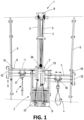
- the described muscle training device shown in figure 1 , basically consists of a support structure (1) and a resistant element (2), linked to the support structure (1) by means of a closed cable (3).
- a user can operate the resistant element (2) by means of pullers (4).
- the resistant element (2) offers a resistance to the displacement performed by the user by means of the pullers (4), which allows to develop a muscular exercise.
- the support structure (1) comprises static elements, which can be fixed to an external fixed structure, wall or vertical wall, and dynamic elements, which allow the position of the pullers (4) to be changed.
- the external fixed structure could be included in a compartment or cabinet to standardize the sizes of the equipment and improve the aesthetics of the whole.
- the static elements of the support structure (1) are central pillars (5) with vertical orientation (Y axis), and lateral pillars (6), parallel to the central pillars (5).
- Y axis vertical orientation
- lateral pillars (6) parallel to the central pillars (5).
- they are anchored to the external fixed structure by means of intermediate plates (7) along their development, and end plates (8) at their upper and lower ends.
- the dynamic elements of the support structure (1) comprise two drive arms (9) movable along the central pillars (5), two corresponding slides (10) movable along the side pillars (6), and two corresponding carriages (11) movable along each of the arms (9), to which the pullers (4) are attached and through which the user performs the exercise.
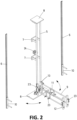
- each of the arms (9) is made up of profiles joined together at their ends to form a rectangle.
- Each arm (9) has an outer end (12), linked to the slides (10), and an inner end (13), linked to the central pillars (5).
- the outer end (12) allows the slides (10) to be anchored to the arm (9) by means of a coupling element, which in this case is a pin.
- the profile of the inner end (13) acts as a sleeve for the arm (9) on its central pillar (5).
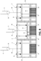
- the Y-axis (vertical) displacement of the arm (9) is allowed, so that it can slide along the central pillars (5) and the lateral pillars (6), as shown in Figure 2 .
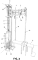
- the turning or rotating movement on the Y-axis is also allowed, as shown in Figure 3 .
- each of the central pillars (5) incorporates a longitudinally welded plate located at the height at which the aforementioned rotation is to be avoided.
- the inner end (13) of the arm (9) has a non-complete circular section, so it does not encounter any opposition in the vertical displacement in the arrangement in which the slides (10) are coupled, but it does when trying to rotate, as it is prevented by this plate.
- the extreme positions of the central pillars (5) do not have this plate and, therefore, the rotation of the arms (9) is allowed so that they can work at 90° to the support structure (1). In this position, the arms (9) would work in a cantilevered position and would therefore have little mechanical resistance, which is why it is necessary to provide them with additional supports.
- Figure 3 shows the two elements designed for this function.
- the arms (9) are attached to the structure of a bench (14), which also expands the exercise possibilities.
- the arms (9) on the central pillars (5) they can rest on an external reinforcement structure (15).
- the external reinforcement structure (15) is freestanding, but could be part of or supported by the bench (14) or anchored to an upper slab.
- each of the arms (9) serve as guides for the respective carriages (11), allowing the displacement of the pullers (4) along the horizontal axis "X".
- Each puller (4) shown in detail in figures 4-5 , comprises in turn a rotating assembly (16) which moves the carriage (11), a free pulley (17) linked to the rotating assembly (16) and a hook (18), which hangs from the free pulley (17) and which in this preferred embodiment is a carabiner, for temporary attachment of handles, knobs, bars and similar elements, to which the user grips in order to operate the puller (4) and thus perform the exercises.
- the rotating assembly (16) allows a 360° rotation of the puller (4), the axis of this rotation coinciding with the generatrix of the closed cable (3) and can be moved along this axis and operate in any position.
- the rotating assembly (16) comprises a part attached to the carriage (11), consisting of two L-shaped elements (33) with a threaded side that is anchored to the carriage (11) and an upper bushing through which the closed cable (3) runs.
- the rotating assembly (16) is completed by two side bushings (19) which act as a sleeve for the L-shaped elements (33) and which are attached to two internal pulleys (21), fixed to support plates (22) which close and cover the rotating assembly (16).
- the internal pulleys (21) guide the closed cable (3) towards the free pulley (17) at all times by means of a 360° rotation.
- the closed cable (3) guided by an inner bush of the L-element (33) which is jacketed by the corresponding side bush (19), passes towards its corresponding internal pulley (21) and towards the free pulley (17) to return towards the other internal pulley (21) and pass through the other inner bush of the L-element (33), itself jacketed by the side bush (19).
- FIG. 1 shows the exploded view of the rotating assembly (16).
- the L-shaped elements (33) guide the closed cable (3) and anchor the puller (4) to the carriage (11).
- the closed cable (3) passes through a plurality of fixed pulleys (23), linked to the support structure (1) and, in any position permitted by the dynamic elements of the support structure (1), transfers the user's effort to the resistant element (2) during the exercise.
- the purpose of the fixed pulleys (23) is to follow the movements of the dynamic elements of the supporting structure (1) without the cable (3) losing tension, so that the transmission of force is effective in any position.
- each of the arms (9) has four fixed pulleys (23), two at the inner end (13) and two at the outer end (12).
- the upper end plate (8) has six, the lower end plate (8) has two, each of the carriages (11) has three and lastly, the resistant element (2) has an additional fixed pulley (23).
- the closed cable (3) coming from the fixed pulleys (23) of the upper end plate (8), travels the following path on the arm (9): upper fixed pulley (23) of the inner end (13), upper fixed pulley (23) of the outer end (12), lower fixed pulley (23) of the outer end (12), fixed pulleys (23) of the carriage (11) and lower fixed pulley (23) of the inner end (13), to thus connect with the two fixed pulleys (23) located on the lower end plate (8).
- the closed cable (3) connects with the opposite arm (9), making the reverse route to reconnect with the fixed pulleys (23) of the upper end plate (8).
- These receive the closed cable (3) from the arms (9), guide it and connect it to a hoist (24) consisting of a triple pulley.
- the hoist (24) shaft is connected to the resistant element (2) by means of a separate connecting cable (25).
- This hoist (24) allows the development of a greater stroke of each puller (4) without having to increase the final size of the device. On the other hand, it is possible to divide the effort that the user makes to lift a resistance, so it is necessary to use more or stiffer resistors.
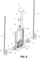
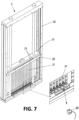
- Figure 7 shows the resistant element (2) of the device.
- the resistant element (2) comprises a fixed frame (26), attachable to the external wall or structure and to the lower end plate (8) of the support structure (1), some elastic elements (27), in this case elastic bands, and a mobile frame (31) that moves along the fixed frame (26), driven by the closed cable (3), dragging one end of the elastic elements (27).
- the fixed frame (26) comprises two vertical columns
- the mobile frame (31) comprises a cross beam that moves along these vertical columns.
- the mobile frame (31) also includes a housing for the connection cable (25) coming from the hoist (24), and holes (29) for the selective insertion of pins that join the free upper end of the elastic elements (27).
- Said elastic elements (27) are fixed solidly by their other lower ends to the fixed frame (26) in any case.
- the hoist (24) rises, as it is the only free pulley in the device.
- This free pulley is to be understood as a pulley that has an allowed relative movement. This movement causes the mobile frame (31) of the resistant element (2) to ascend, activating the resistance for the user to develop the muscular exercise.
- the device also incorporates at least one load cell (30) to traction, linked to the elastic elements (27), which allows to know the instantaneous power exerted during the development of the traction exercise of the elastic elements (27). The measurement of this power over time thus makes it possible to know the energy developed by the user.
- the load cell (30) is preferably located between a lower profile of the fixed frame (26), and a profile which is solidary to all the fastening elements, and each of these fastening elements is solidary to one of the elastic elements (27) at its lower end.
- control unit linked to the traction load cell (30), and equipped with display elements such as a screen or similar, for reading, storing, processing, sending and displaying the information collected by said load cell (30).
Landscapes
- Health & Medical Sciences (AREA)
- General Health & Medical Sciences (AREA)
- Physical Education & Sports Medicine (AREA)
- Life Sciences & Earth Sciences (AREA)
- Biophysics (AREA)
- Orthopedic Medicine & Surgery (AREA)
- Engineering & Computer Science (AREA)
- Multimedia (AREA)
- Human Computer Interaction (AREA)
- Rehabilitation Tools (AREA)
Claims (9)
- Muskeltrainingsgerät umfassend:- eine Tragstruktur (1) bestehend aus:- statischen Elementen, die an einer externen festen Struktur befestigt werden können, und- dynamischen Elementen,- mindestens einen Zugelement (4), der von einem Benutzer bewegt und benutzt werden kann,- ein Widerstandselement (2), das mit der Tragstruktur (1) verbunden ist und einen Widerstand gegen mindestens einen Zugelement (4) für die Ausführung einer Muskelübung ausübt,- feste Rollen (23), die mit der Tragstruktur (1) verbunden sind,- eine Hebevorrichtung (24), die mit der Tragstruktur (1) und dem Widerstandselement (2) verbunden ist,- ein geschlossenes Seil, ohne freie Enden, das nicht an der Tragstruktur (1) verankert ist und das über die festen Rollen (23) und die Hebevorrichtung (24) mit dem Widerstandselement (2) und der Tragstruktur (1) verbunden ist und das - mittels mindestens einem Zugelement (4) betätigt werden kann, so dass mindestens zwei Freiheitsgrade der Verschiebung und/oder Drehung in dem Zugelement (4) möglich sind,wobei das Gerät dadurch gekennzeichnet ist, dass- die statistischen Elemente zwei vertikale Mittelpfosten (5) und zwei Seitenpfosten (6), die parallel zu den Mittelpfosten (5) angeordnet sind, umfassen,- die dynamischen Elemente umfassen:- mindestens einen Antriebsarm (9), der gleichzeitig entlang eines Mittelpfostens (5) und eines Seitenpfostens (6) bewegbar ist.- mindestens einen Schlitten (11), der entlang jedem Arm (9) beweglich ist und an mindestens einem Zugelement (4) befestigt ist,- ein Gleitelement (10), das mit mindestens einem Antriebsarm (9) und dem entsprechenden Seitenpfosten (6) verbunden ist, so dass mindestens ein Antriebsarm (9) entlang des entsprechenden Mittelpfostens (5) und des entsprechenden Seitenpfostens (6) gleiten kann.
- Muskeltrainingsgerät nach Anspruch 1,
wobei jeder Arm (9) umfasst:- ein äußeres Ende (12), das mit dem entsprechenden Schlitten (11) durch ein Kupplungselement verbunden ist, das von dem Schlitten (11) abgekoppelt werden kann,- ein inneres Ende (13), das mit dem entsprechenden Mittelpfosten (5) verbunden ist und das dem Arm (9) ermöglicht entlang des Mittelpfostens (5) zu gleiten, so dass das innere Ende (13) eine Drehung des Arms (9) um die Achse des Mittelfpfostens (5) nach dem Lösen des äußeren Endes (12) von dem entsprechenden Schlitten (11) ermöglicht. - Muskeltrainingsgerät nach einem der vorherigen Ansprüche,
wobei die Mittelpfosten (5) der Tragstruktur (1) zusätzlich umfassen:- Zwischenplatten (7), die entlang ihrer Ausdehnung befestigt sind,- Endplatten (8), die an ihren oberen und unteren Enden befestigt sind, zur Verstärkung der Verbindung mit der externen festen Struktur und zur Verbesserung der strukturellen Festigkeit der Vorrichtung - Muskeltrainingsgerät nach einem der vorherigen Ansprüche,
wobei das Widerstandselement (2) umfasst:- einen festen Rahmen (26), der an der externen Struktur und an der Tragstruktur (1) befestigt werden kann,- elastische Elemente (27), die an einem Ende des festen Rahmens (26) befestigt sind,- ein oberes Profil (31), das sich entlang des festen Rahmens (26) bewegt, angetrieben durch das geschlossene Seil, das das andere Ende des elastischen Elements (27) zieht. - Muskeltrainingsgerät nach Anspruch 4,
das weiter mindestens ein Zugkraftmesszelle (30) aufweist, die mit dem elastischen Element (27) verbunden ist, um die ausgeübte Momentanleistung, während der Zugübung der elastischen Elemente (27) zu bestimmen. - Muskeltrainingsgerät nach Anspruch 5,
das weiter eine Steuereinheit aufweist, die mit der Messzelle (30) verbunden ist und mit einem Anzeigeelement, zum Lesen, Speichern, Verarbeiten, Senden und Anzeigen der von der mindestens einen Messzelle (30) erfassten Informationen versehen ist. - Zugelement (4) für ein Muskeltrainingsgerät nach Anspruch 1,wobei das Gerät mindestens ein geschlossenes Seil (3) umfasst, wobei das Zugelement (4) dadurch gekennzeichnet ist, dass es umfasst:- eine Drehvorrichtung (16), die sich dreht und entlang der Achse der Mantellinie des geschlossenen Seils bewegt,- eine freie Rolle (17), die mit der Drehvorrichtung verbunden ist,- einen Haken (18), der an der freien Rolle (17) hängt, zum vorübergehenden Befestigen eines Griffelements eines Benutzers,so, dass die Drehvorrichtung (16) eine 360° Drehung des Zugelements (4) ermöglicht, wobei die Achse dieser Drehung mit einer Längsachse des Seils (3) übereinstimmt.
- Zugelement (4) nach Anspruch 7, wobei die Drehvorrichtung (16) umfasst:- zwei L-förmige Elemente (33), die das geschlossenen Führen des Seils (3) und das Verankern der Vorrichtung (16) an einem Element ermöglichen,- zwei obere Buchsen (19), die auf den L-förmigen Elementen (33) drehen können,- Stützplatten (22) zum Schließen, Abdecken und Stützen der oberen Buchsen (19),- interne Rollen (21) und interne Buchsen (20), die an den Stützplatten (22) befestig sind, um das Seil (3) zur freien Rolle (17) zu führen.
- Muskeltrainingssatz, umfassend:- ein Muskeltrainingsgerät nach einem der Ansprüche 1-6,- mindestens ein Zugelement (4) nach einem der Ansprüche 7-8,wobei der Satz dadurch gekennzeichnet ist, dass:- das geschlossene Seil (3), ohne freie Enden, durch das Zugelement (4) verläuft und zum Zugelement (4) durchgesteckt ist,- die Drehvorrichtung (16) am Schlitten (11) verankert werden kann und das Zugelement (4) dadurch mit der Verschiebung des Schlittens (11) verbunden ist, so dass mittels der festen Rollen (23) und der Hebevorrichtung (24) das Zugelement (4) bei Betätigung auf das Widerstandelement (2) wirkt und dadurch die Betätigung des Zugelements (4) in jeder Position, die die dynamischen Elemente der Struktur erzeugen, möglich ist, dank seiner zwei oder mehreren Freiheitsgrade und für jeden von der Drehvorrichtung (16) möglichen Winkel.
Priority Applications (2)
| Application Number | Priority Date | Filing Date | Title |
|---|---|---|---|
| ES21383060T ES3037177T3 (en) | 2021-11-24 | 2021-11-24 | Muscle training device, training device puller and training set |
| EP21383060.7A EP4186569B1 (de) | 2021-11-24 | 2021-11-24 | Muskeltrainingsvorrichtung, trainingsvorrichtungszieher und trainingsset |
Applications Claiming Priority (1)
| Application Number | Priority Date | Filing Date | Title |
|---|---|---|---|
| EP21383060.7A EP4186569B1 (de) | 2021-11-24 | 2021-11-24 | Muskeltrainingsvorrichtung, trainingsvorrichtungszieher und trainingsset |
Publications (3)
| Publication Number | Publication Date |
|---|---|
| EP4186569A1 EP4186569A1 (de) | 2023-05-31 |
| EP4186569B1 true EP4186569B1 (de) | 2025-06-18 |
| EP4186569C0 EP4186569C0 (de) | 2025-06-18 |
Family
ID=79024053
Family Applications (1)
| Application Number | Title | Priority Date | Filing Date |
|---|---|---|---|
| EP21383060.7A Active EP4186569B1 (de) | 2021-11-24 | 2021-11-24 | Muskeltrainingsvorrichtung, trainingsvorrichtungszieher und trainingsset |
Country Status (2)
| Country | Link |
|---|---|
| EP (1) | EP4186569B1 (de) |
| ES (1) | ES3037177T3 (de) |
Family Cites Families (7)
| Publication number | Priority date | Publication date | Assignee | Title |
|---|---|---|---|---|
| US6443877B1 (en) * | 1999-02-11 | 2002-09-03 | Dietrich Hoecht | Compact, multi-choice exercise apparatus |
| US7094185B2 (en) * | 2002-01-17 | 2006-08-22 | Darrell Greenland | Versatile exercise machine |
| ITBO20040408A1 (it) | 2004-06-29 | 2004-09-29 | Emmeci S R L | Rivestitrice per scatole da imballaggio |
| US20070161472A1 (en) * | 2005-09-02 | 2007-07-12 | Drechsler Arthur J | Uniquely multi-functional exercise device |
| CN101495193B (zh) * | 2006-05-16 | 2012-02-29 | 詹姆斯·佳·庄 | 多功能个人健身器材 |
| US7632221B1 (en) | 2006-10-23 | 2009-12-15 | Scott Kolander | Cable cross trainer apparatus |
| US10532239B1 (en) | 2018-01-18 | 2020-01-14 | Denis Suarez Monne | Apparatus for exercising |
-
2021
- 2021-11-24 ES ES21383060T patent/ES3037177T3/es active Active
- 2021-11-24 EP EP21383060.7A patent/EP4186569B1/de active Active
Also Published As
| Publication number | Publication date |
|---|---|
| ES3037177T3 (en) | 2025-09-29 |
| EP4186569A1 (de) | 2023-05-31 |
| EP4186569C0 (de) | 2025-06-18 |
Similar Documents
| Publication | Publication Date | Title |
|---|---|---|
| US7927262B2 (en) | Compact multi-function exercise apparatus | |
| TWI750890B (zh) | 運動儲存系統 | |
| US9302136B2 (en) | Three-point adjustment multi-purpose exercise machine | |
| US6592498B1 (en) | Exercise devices | |
| US5499959A (en) | Upper body exercise apparatus | |
| US8096926B1 (en) | Multi resistance ratio exercise apparatus | |
| US5407403A (en) | Forced repetition assist device | |
| US4836535A (en) | Upper body building machine | |
| US10426989B2 (en) | Cable system incorporated into a treadmill | |
| JP4701165B2 (ja) | トレーニング器具 | |
| KR102053685B1 (ko) | 전동제어식 복합 피트니스 머신 | |
| EP1493467B1 (de) | Übungsgeräte | |
| US12303739B1 (en) | Exercise machine system and method of use | |
| US20180326241A1 (en) | Exercise and Rehabilitation Machine with Autonomous Drive | |
| US12415109B1 (en) | Foldable small flying and squat rack | |
| WO2024030309A1 (en) | Dual action weightlifting machine with selectorized resistance | |
| AT508321A1 (de) | Multifunktions fitnessgerät | |
| US12318657B1 (en) | Exercise machine system and method of use | |
| EP4186569B1 (de) | Muskeltrainingsvorrichtung, trainingsvorrichtungszieher und trainingsset | |
| US8715142B1 (en) | User-adjustable resistance mechanisms and exercise apparatuses employing the same | |
| US20170007876A1 (en) | Exercise Apparatus | |
| US20260027400A1 (en) | Hybrid resistance generation system for an exercise machine | |
| CN220736095U (zh) | 六点综合训练器 | |
| CN216676834U (zh) | 一种智能组合健身机器 | |
| CA2675186A1 (en) | Rotative handle |
Legal Events
| Date | Code | Title | Description |
|---|---|---|---|
| PUAI | Public reference made under article 153(3) epc to a published international application that has entered the european phase |
Free format text: ORIGINAL CODE: 0009012 |
|
| STAA | Information on the status of an ep patent application or granted ep patent |
Free format text: STATUS: THE APPLICATION HAS BEEN PUBLISHED |
|
| AK | Designated contracting states |
Kind code of ref document: A1 Designated state(s): AL AT BE BG CH CY CZ DE DK EE ES FI FR GB GR HR HU IE IS IT LI LT LU LV MC MK MT NL NO PL PT RO RS SE SI SK SM TR |
|
| STAA | Information on the status of an ep patent application or granted ep patent |
Free format text: STATUS: REQUEST FOR EXAMINATION WAS MADE |
|
| 17P | Request for examination filed |
Effective date: 20230622 |
|
| RBV | Designated contracting states (corrected) |
Designated state(s): AL AT BE BG CH CY CZ DE DK EE ES FI FR GB GR HR HU IE IS IT LI LT LU LV MC MK MT NL NO PL PT RO RS SE SI SK SM TR |
|
| GRAP | Despatch of communication of intention to grant a patent |
Free format text: ORIGINAL CODE: EPIDOSNIGR1 |
|
| STAA | Information on the status of an ep patent application or granted ep patent |
Free format text: STATUS: GRANT OF PATENT IS INTENDED |
|
| RIC1 | Information provided on ipc code assigned before grant |
Ipc: A63B 21/00 20060101AFI20240214BHEP |
|
| INTG | Intention to grant announced |
Effective date: 20240301 |
|
| GRAJ | Information related to disapproval of communication of intention to grant by the applicant or resumption of examination proceedings by the epo deleted |
Free format text: ORIGINAL CODE: EPIDOSDIGR1 |
|
| STAA | Information on the status of an ep patent application or granted ep patent |
Free format text: STATUS: REQUEST FOR EXAMINATION WAS MADE |
|
| INTC | Intention to grant announced (deleted) | ||
| GRAP | Despatch of communication of intention to grant a patent |
Free format text: ORIGINAL CODE: EPIDOSNIGR1 |
|
| STAA | Information on the status of an ep patent application or granted ep patent |
Free format text: STATUS: GRANT OF PATENT IS INTENDED |
|
| INTG | Intention to grant announced |
Effective date: 20240807 |
|
| GRAJ | Information related to disapproval of communication of intention to grant by the applicant or resumption of examination proceedings by the epo deleted |
Free format text: ORIGINAL CODE: EPIDOSDIGR1 |
|
| STAA | Information on the status of an ep patent application or granted ep patent |
Free format text: STATUS: REQUEST FOR EXAMINATION WAS MADE |
|
| INTC | Intention to grant announced (deleted) | ||
| GRAS | Grant fee paid |
Free format text: ORIGINAL CODE: EPIDOSNIGR3 |
|
| STAA | Information on the status of an ep patent application or granted ep patent |
Free format text: STATUS: GRANT OF PATENT IS INTENDED |
|
| GRAP | Despatch of communication of intention to grant a patent |
Free format text: ORIGINAL CODE: EPIDOSNIGR1 |
|
| INTG | Intention to grant announced |
Effective date: 20250124 |
|
| GRAA | (expected) grant |
Free format text: ORIGINAL CODE: 0009210 |
|
| STAA | Information on the status of an ep patent application or granted ep patent |
Free format text: STATUS: THE PATENT HAS BEEN GRANTED |
|
| AK | Designated contracting states |
Kind code of ref document: B1 Designated state(s): AL AT BE BG CH CY CZ DE DK EE ES FI FR GB GR HR HU IE IS IT LI LT LU LV MC MK MT NL NO PL PT RO RS SE SI SK SM TR |
|
| REG | Reference to a national code |
Ref country code: GB Ref legal event code: FG4D |
|
| REG | Reference to a national code |
Ref country code: CH Ref legal event code: EP |
|
| REG | Reference to a national code |
Ref country code: DE Ref legal event code: R096 Ref document number: 602021032419 Country of ref document: DE |
|
| REG | Reference to a national code |
Ref country code: CH Ref legal event code: EP |
|
| REG | Reference to a national code |
Ref country code: IE Ref legal event code: FG4D |
|
| U01 | Request for unitary effect filed |
Effective date: 20250711 |
|
| U07 | Unitary effect registered |
Designated state(s): AT BE BG DE DK EE FI FR IT LT LU LV MT NL PT RO SE SI Effective date: 20250717 |
|
| REG | Reference to a national code |
Ref country code: ES Ref legal event code: FG2A Ref document number: 3037177 Country of ref document: ES Kind code of ref document: T3 Effective date: 20250929 |
|
| PG25 | Lapsed in a contracting state [announced via postgrant information from national office to epo] |
Ref country code: GR Free format text: LAPSE BECAUSE OF FAILURE TO SUBMIT A TRANSLATION OF THE DESCRIPTION OR TO PAY THE FEE WITHIN THE PRESCRIBED TIME-LIMIT Effective date: 20250919 Ref country code: NO Free format text: LAPSE BECAUSE OF FAILURE TO SUBMIT A TRANSLATION OF THE DESCRIPTION OR TO PAY THE FEE WITHIN THE PRESCRIBED TIME-LIMIT Effective date: 20250918 |
|
| PG25 | Lapsed in a contracting state [announced via postgrant information from national office to epo] |
Ref country code: HR Free format text: LAPSE BECAUSE OF FAILURE TO SUBMIT A TRANSLATION OF THE DESCRIPTION OR TO PAY THE FEE WITHIN THE PRESCRIBED TIME-LIMIT Effective date: 20250618 |
|
| PG25 | Lapsed in a contracting state [announced via postgrant information from national office to epo] |
Ref country code: RS Free format text: LAPSE BECAUSE OF FAILURE TO SUBMIT A TRANSLATION OF THE DESCRIPTION OR TO PAY THE FEE WITHIN THE PRESCRIBED TIME-LIMIT Effective date: 20250918 |
|
| U20 | Renewal fee for the european patent with unitary effect paid |
Year of fee payment: 5 Effective date: 20251010 |
|
| PG25 | Lapsed in a contracting state [announced via postgrant information from national office to epo] |
Ref country code: IS Free format text: LAPSE BECAUSE OF FAILURE TO SUBMIT A TRANSLATION OF THE DESCRIPTION OR TO PAY THE FEE WITHIN THE PRESCRIBED TIME-LIMIT Effective date: 20251018 |
|
| PG25 | Lapsed in a contracting state [announced via postgrant information from national office to epo] |
Ref country code: SM Free format text: LAPSE BECAUSE OF FAILURE TO SUBMIT A TRANSLATION OF THE DESCRIPTION OR TO PAY THE FEE WITHIN THE PRESCRIBED TIME-LIMIT Effective date: 20250618 |
|
| PG25 | Lapsed in a contracting state [announced via postgrant information from national office to epo] |
Ref country code: CZ Free format text: LAPSE BECAUSE OF FAILURE TO SUBMIT A TRANSLATION OF THE DESCRIPTION OR TO PAY THE FEE WITHIN THE PRESCRIBED TIME-LIMIT Effective date: 20250618 |
|
| PG25 | Lapsed in a contracting state [announced via postgrant information from national office to epo] |
Ref country code: PL Free format text: LAPSE BECAUSE OF FAILURE TO SUBMIT A TRANSLATION OF THE DESCRIPTION OR TO PAY THE FEE WITHIN THE PRESCRIBED TIME-LIMIT Effective date: 20250618 |
|
| PG25 | Lapsed in a contracting state [announced via postgrant information from national office to epo] |
Ref country code: SK Free format text: LAPSE BECAUSE OF FAILURE TO SUBMIT A TRANSLATION OF THE DESCRIPTION OR TO PAY THE FEE WITHIN THE PRESCRIBED TIME-LIMIT Effective date: 20250618 |
|
| PGFP | Annual fee paid to national office [announced via postgrant information from national office to epo] |
Ref country code: ES Payment date: 20251201 Year of fee payment: 5 |
|
| PLBE | No opposition filed within time limit |
Free format text: ORIGINAL CODE: 0009261 |
|
| STAA | Information on the status of an ep patent application or granted ep patent |
Free format text: STATUS: NO OPPOSITION FILED WITHIN TIME LIMIT |