EP4186417A1 - Coronary artery stenosis quantification using 3d flow mri - Google Patents
Coronary artery stenosis quantification using 3d flow mri Download PDFInfo
- Publication number
- EP4186417A1 EP4186417A1 EP21210258.6A EP21210258A EP4186417A1 EP 4186417 A1 EP4186417 A1 EP 4186417A1 EP 21210258 A EP21210258 A EP 21210258A EP 4186417 A1 EP4186417 A1 EP 4186417A1
- Authority
- EP
- European Patent Office
- Prior art keywords
- flow
- additional
- heart
- segments
- space data
- Prior art date
- Legal status (The legal status is an assumption and is not a legal conclusion. Google has not performed a legal analysis and makes no representation as to the accuracy of the status listed.)
- Granted
Links
Images

Classifications
-
- A—HUMAN NECESSITIES
- A61—MEDICAL OR VETERINARY SCIENCE; HYGIENE
- A61B—DIAGNOSIS; SURGERY; IDENTIFICATION
- A61B5/00—Measuring for diagnostic purposes; Identification of persons
- A61B5/02—Detecting, measuring or recording for evaluating the cardiovascular system, e.g. pulse, heart rate, blood pressure or blood flow
- A61B5/026—Measuring blood flow
- A61B5/0263—Measuring blood flow using NMR
-
- A—HUMAN NECESSITIES
- A61—MEDICAL OR VETERINARY SCIENCE; HYGIENE
- A61B—DIAGNOSIS; SURGERY; IDENTIFICATION
- A61B2576/00—Medical imaging apparatus involving image processing or analysis
- A61B2576/02—Medical imaging apparatus involving image processing or analysis specially adapted for a particular organ or body part
- A61B2576/023—Medical imaging apparatus involving image processing or analysis specially adapted for a particular organ or body part for the heart
-
- A—HUMAN NECESSITIES
- A61—MEDICAL OR VETERINARY SCIENCE; HYGIENE
- A61B—DIAGNOSIS; SURGERY; IDENTIFICATION
- A61B5/00—Measuring for diagnostic purposes; Identification of persons
- A61B5/05—Detecting, measuring or recording for diagnosis by means of electric currents or magnetic fields; Measuring using microwaves or radio waves
- A61B5/055—Detecting, measuring or recording for diagnosis by means of electric currents or magnetic fields; Measuring using microwaves or radio waves involving electronic [EMR] or nuclear [NMR] magnetic resonance, e.g. magnetic resonance imaging
Definitions
- the present application relates to a method for determining a flow parameter in a coronary artery of the heart. Furthermore, the magnetic resonance imaging system is provided configured to determine the flow parameter, a computer program comprising program code and a carrier comprising the computer program.
- Coronary Artery Disease is caused by plaque in the coronary arteries that lead to a stenosis (narrowing) and may lead to a block of blood flow which could lead to e.g. a Heart Attack.
- CAD Coronary Artery Disease
- a non-invasive diagnosis and quantification of a stenosis remains unreliable, especially because the decision to invasively treat a stenosis is directly related to a quantification of the hemodynamic relevance (blood flow and pressure) which can only be insufficiently measured non-invasively.
- a method for determining a flow parameter in a coronary artery of the heart comprises, at a magnetic resonance imaging system the steps of determining a heartbeat of the heart. Furthermore, MR signals of the heart are detected taking into account the heartbeat using a 3D imaging sequence of a region of interest comprising the heart, wherein the 3D imaging sequence is a segmented imaging sequence comprising flow encoding segments in which additional flow encoding gradients are switched in different gradient directions, wherein the 3D imaging sequence furthermore comprises additional segments without additional flow encoding gradients.
- a plurality of 3D k-space data sets are generated from the detected MR signals which were detected in the additional segments and the flow encoding segments.
- At least one morphological MR image of the heart is generated showing at least one coronary artery of the heart based on the detected MR signals. Furthermore a quantitative flow parameter of blood flowing in the coronary artery is determined taking into account the flow encoding segments and the additional segments.
- This method allows direct, noninvasive measurement of flow in the coronary artery together with the generation of a morphological image of the coronary artery.
- the additional flow encoding gradients are switched in three different directions, so that one 3D flow k-space data set is obtained for each of the gradient directions and one additional 3D k-space data set is obtained without the additional flow encoding gradients.
- the quantitative flow parameter is determined based on the 3D flow k-space data sets and the one additional 3D k-space data set.
- one k-space line of the corresponding k-space data set is acquired in each of the flow encoding segments and the additional segments which are acquired in an interleaved way.
- this is done for each velocity direction so that one k-space line is acquired in the acquisition block, the flow encoding segment, for each of three velocity directions.
- the quantitative flow parameter can be a hemodynamic parameter in the at least one coronary artery.
- the quantitative flow parameter can include the determination of a flow vector including a magnitude and the direction of the blood flow in a three-dimensional space, preferably per pixel in the generated image, which can be the morphological image.
- the quantitative flow parameter can include a Fractional Flow Reserve, FFR.
- the at least one morphological MR image showing the coronary artery can be generated based on the 3D flow k-space data sets and the one additional 3D k-space data set. Compared to a normal 3D imaging sequence without the flow encoding segments, this means that there are four times more k-space data points available for the image reconstruction. Accordingly it is possible to either increase the quality such as the signal-to-noise ratio of the morphological image, or it is possible to generate the MR image based on only partially acquired k-space data sets so that the image acquisition time can be reduced. As the flow information and the morphological image are both generated from the same data sets, a registration of the flow parameter to the image data is not necessary.
- each of the 3D flow k-space data sets and the additional 3D k-space data set is not fully sampled and the at least one morphological MR image is generated from a combined k-space data set which combines the undersampled data sets.
- the at least one morphological MR image can be generated using a compressed sensing technology or any other constrained reconstruction scheme. This allows to keep the total acquisition time in an acceptable range such as below 10 minutes.
- the acquisition of the MR signals can be limited to a diastolic phase of a cardiac cycle of the heart, at least for the flow encoding segments and preferably for all segments of the image acquisition.
- the coronary arteries In the diastolic phase the coronary arteries have the maximum blood flow and furthermore the movement of the heart is comparatively low in this phase of the cardiac cycle.
- the quantitative flow parameter is obtained as spatially resolved flow parameter obtained at least for a part of the coronary artery.
- both the spatially resolved quantitative flow parameter and the at least one morphological MR images are both generated from the 3D flow k-space data sets and the additional 3D k-space data set so that the spatially resolved quantitative flow parameter and at least one morphological MR image are registered to each other.
- the encoding of the magnitude MR signals and the phase which is used for the flow signal is achieved simultaneously so that a precise location of the flow parameter is possible.
- control module which is configured to carry out the method mentioned above or as discussed in further detail below.
- a computer program comprising program code to be executed by the at least one control module of the magnetic resonance imaging system wherein the execution of the program code causes the imaging system to carry out a method as mentioned above or as discussed in detail below.
- a carrier comprising the computer program wherein the carrier is one of an electronic signal, optical signal, radio signal, and computer readable storage medium.
- the invention allows the direct, non-invasive measurement of the hemodynamic relevance of a coronary artery stenosis. It combines and adapts several CMR techniques, namely CMR-based coronary angiography and CMR-based flow quantification using phase-contrast MRI.
- Fig. 1 shows a schematic view of an MR imaging system 9, which comprises a magnet 10 generating the magnetic field B0.
- the patient or object under examination 13 lying on a table 12 is moved into the center of the MR imaging system 9, where the MR signals can be detected after excitation by RF pulses using coils 11.
- the nuclear spins of object 13, especially the part located in the receiving coils are excited and location coded currents induced by relaxation can be detected.
- the way how MR images, especially 3D image data sets are generated and how the MR signals are detected, using a sequence of RF pulses and a sequence of magnetic field gradients, is known in the art, so that a detailed general explanation thereof is omitted.
- the MR system may furthermore comprise shim coils 8 which are used to correct in-homogeneities of the magnetic field B0.
- the MR imaging system 9 comprises a control module 50 which is used for controlling the MR imaging system.
- the control module 50 comprises a gradient control unit 14 for controlling and switching the magnetic field gradients, an RF control unit 15 for controlling and generating RF pulses for the imaging sequences.
- the image sequence control unit 16 is provided to control the sequence of the applied RF pulses and magnetic field gradients and thus is also configured to partly control the gradient control unit 14 and the RF control unit 15.
- computer programs needed for operating the MR imaging system and the imaging sequences necessary for generating the MR images can be stored together with the generated MR images.
- the MR images and any further information can be displayed on a display 18 wherein a human machine interface 19 is provided, which can be used by an operator of the MR imaging system to control the MR imaging system.
- a flow quantification unit 20 is provided configured to quantify a flow parameter in a coronary artery shown in the generated MR images.
- Unit 20 can be configured to determine a flow vector pixel-wise so that a stenosis can be identified by comparing the flow vectors from the different pixels.
- a central processing unit 21 can coordinate the operation of the different functional units shown in Fig. 1 and can comprise one or more processors, which can carry out instructions stored on the memory 17.
- the memory can include program code to be executed by the processing unit 21.
- control module especially gradient control unit 14, the RF control unit 15, the image sequence control unit 16, and flow quantification unit 20 can be configured to quantify flow in the coronary artery using 3D k-space data sets of the patient 13 as will be explained in detail further below.
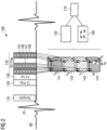
- Fig. 2 shows an example of an imaging sequence with which a morphological image of the coronary arteries is possible together with a quantification of the flow in the coronary arteries.
- the heartbeat of the examined person is monitored such as the ECG signal 80 where the R wave 81 is shown symbolically.
- the imaging sequence 100 is a 3D flow sequence which can be used to measure the fractional flow reserve, FFR.
- FFR fractional flow reserve
- any related hemodynamic quantity can be deducted from this 3D vector field. These include: maximum flow, flow volume, flow profiles, pressure gradients along the coronary artery, helicity, vorticity, etc.
- a navigator 110 is played out.
- a T2 contrast preparation module 120 is played out followed by a fat saturation module 130.
- the 3D flow acquisition block 140 acquires sequentially at least one k-space line in each velocity direction.
- the flow encoding is obtained with additional encoding gradients which are applied in the three different gradient directions.
- additional gradients are applied in the x-direction.
- each of the segments 145-148 at least one k-space line of each velocity direction including of a reference 148 where no additional flow encoding gradient is played out is acquired.
- a morphological MR image 150 of the heart can be generated using the four different data sets 141-144.
- the image can be reconstructed using construction techniques such as compressed sensing.
- different image data sets are provided it is possible to further reduce the amount of k-space lines acquired in each data set 141-144.
- the signal-to-noise ratio could be improved as the morphological image can be reconstructed based on four data sets when these data sets are each fully acquired or the undersampling is at least reduced.
- the data sets 141 to 144 are used to generate an image 160 with spatially resolved blood flow velocity in the coronary arteries or any other artery in the image as symbolized by the arrows in image 160.
- Images 150 and 160 can be combined to generate an image 170 which is a morphological image which also shows the flow information in the coronary arteries, e.g. the flow information may be color coded into the image.
- the k-space lines are only acquired in a period of the heartbeat in which the coronary arteries have the maximum blood flow, this means that the image segments are acquired during the diastolic period of the cardiac cycle.
- the described technology can take advantage of all improved coronary angiography CMR techniques such as Fat Sat, prescan motion compensation, resting phase definition etc. This can lead to an optimal contrast in the morphological image of the coronary arteries while additionally measuring the blood flow in 3D through the coronary arteries encoded in the phase of the signal. As all the four data sets are used for the morphological image in the flow determination, both morphology and flow will be automatically registered to each other.
- the 3D flow CMR measurement therefore has all the advantages of the coronary angiography CMR in addition to directly measuring the hemodynamics in the arteries.
- the scan time as compared to standard coronary angiography is increased by a factor of 4, however, the signal-to-noise ratio is doubled and the similarity of each flow encoding acquisition can lead to a higher acceleration factor which can be used in compressed sensing reconstruction.
- the proposed technique can measure the blood flow directly and does not need any computational fluid dynamic calculations nor prior assumptions regarding boundary conditions.
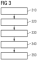
- Fig. 3 summarizes some of the steps carried out during the quantitative determination of the flow parameter in the coronary artery.
- the heartbeat of the heart is determined, by way of example using the ECG signal of the heart as shown in Fig. 2 .
- the MR signals of the heart are detected in step 320 wherein the 3D imaging sequence as discussed in connection with Fig. 2 is used.
- the imaging sequence is an imaging sequence comprising different segments such as the flow encoding segments 145, 146, 147 in which additional flow encoding gradients are switched in different directions.
- the imaging sequence comprises a segment 148 without additional flow encoding gradients which are just switched in addition to the other gradients in order to encode flow.
- step 330 after several heartbeats the 3D the k-space data sets 141-144 are generated/obtained.
- step 340 at least one morphological MR image of the heart is generated which shows one or several coronary arteries of the heart.
- step 350 it is possible in step 350 to determine the quantitative flow parameter of the blood flow in the coronary artery such as the fractional flow reserve, FFR, however it should be noted that any other flow parameter such as the absolute flow velocity or relative changes may be determined.
- FFR fractional flow reserve
Landscapes
- Health & Medical Sciences (AREA)
- Life Sciences & Earth Sciences (AREA)
- Engineering & Computer Science (AREA)
- Medical Informatics (AREA)
- Physics & Mathematics (AREA)
- Cardiology (AREA)
- Biophysics (AREA)
- Pathology (AREA)
- Hematology (AREA)
- Biomedical Technology (AREA)
- Heart & Thoracic Surgery (AREA)
- Physiology (AREA)
- Molecular Biology (AREA)
- Surgery (AREA)
- Animal Behavior & Ethology (AREA)
- General Health & Medical Sciences (AREA)
- Public Health (AREA)
- Veterinary Medicine (AREA)
- Magnetic Resonance Imaging Apparatus (AREA)
Abstract
Description
- The present application relates to a method for determining a flow parameter in a coronary artery of the heart. Furthermore, the magnetic resonance imaging system is provided configured to determine the flow parameter, a computer program comprising program code and a carrier comprising the computer program.
- Coronary Artery Disease (CAD) is caused by plaque in the coronary arteries that lead to a stenosis (narrowing) and may lead to a block of blood flow which could lead to e.g. a Heart Attack. CAD is the most common cardiovascular disease and is amongst the main cause of death worldwide. Its economic burden is huge. A non-invasive diagnosis and quantification of a stenosis remains unreliable, especially because the decision to invasively treat a stenosis is directly related to a quantification of the hemodynamic relevance (blood flow and pressure) which can only be insufficiently measured non-invasively.
- Currently, the hemodynamic relevance of a stenosis can be assessed in the following way.
- Invasively, under X-RAY (Angiography), pressure measurements can be taken distal and proximal of the stenosis by inserting a catheter into the artery. These pressure measurements define the so-called Fractional Flow Reserve (FFR). A cut-off value (in the order of 0.8) is defined, over which the stenosis are deemed 'hemodynamically relevant', leading to a decision to treat the stenosis (using a stent, for instance)
- Non-invasively using cardiovascular magnetic resonance imaging (CMR), a cardiac perfusion acquisition can be performed (under stress). A perfusion defect of the myocardium is an indirect measurement of a hemodynamic relevant stenosis. In this case, the coronary artery is not measured directly, but only the effect of a potential blood flow block is measured in the heart muscle. This measurement is typically only performed in 2D due to scan time limitations.
- Virtual FFR: Based on CT angiography and computational fluid dynamic simulations, a virtual FFR can be calculated. The CT needs ionizing radiation and the calculation of the Virtual FFR is based on many assumptions and boundary conditions which are not measured. It therefore includes many unknowns (such as pressure and flow) for the derivation of a hemodynamic parameter which increases the inaccuracy of this measure.
- Accordingly, a need exists to provide a reliable method to assess the hemodynamic relevance of a stenosis in the coronary arteries of the heart.
- This need is met by the features of the independent claims. Further aspects are described in the dependent claims.
- According to a first aspect, a method for determining a flow parameter in a coronary artery of the heart is provided. The method comprises, at a magnetic resonance imaging system the steps of determining a heartbeat of the heart. Furthermore, MR signals of the heart are detected taking into account the heartbeat using a 3D imaging sequence of a region of interest comprising the heart, wherein the 3D imaging sequence is a segmented imaging sequence comprising flow encoding segments in which additional flow encoding gradients are switched in different gradient directions, wherein the 3D imaging sequence furthermore comprises additional segments without additional flow encoding gradients. A plurality of 3D k-space data sets are generated from the detected MR signals which were detected in the additional segments and the flow encoding segments. Furthermore at least one morphological MR image of the heart is generated showing at least one coronary artery of the heart based on the detected MR signals. Furthermore a quantitative flow parameter of blood flowing in the coronary artery is determined taking into account the flow encoding segments and the additional segments.
- This method allows direct, noninvasive measurement of flow in the coronary artery together with the generation of a morphological image of the coronary artery.
- Preferably, the additional flow encoding gradients are switched in three different directions, so that one 3D flow k-space data set is obtained for each of the gradient directions and one additional 3D k-space data set is obtained without the additional flow encoding gradients. The quantitative flow parameter is determined based on the 3D flow k-space data sets and the one additional 3D k-space data set.
- Preferably, in each of the flow encoding segments and the additional segments which are acquired in an interleaved way, one k-space line of the corresponding k-space data set is acquired. Preferably this is done for each velocity direction so that one k-space line is acquired in the acquisition block, the flow encoding segment, for each of three velocity directions.
- The quantitative flow parameter can be a hemodynamic parameter in the at least one coronary artery.
- The quantitative flow parameter can include the determination of a flow vector including a magnitude and the direction of the blood flow in a three-dimensional space, preferably per pixel in the generated image, which can be the morphological image. The quantitative flow parameter can include a Fractional Flow Reserve, FFR.
- The at least one morphological MR image showing the coronary artery can be generated based on the 3D flow k-space data sets and the one additional 3D k-space data set. Compared to a normal 3D imaging sequence without the flow encoding segments, this means that there are four times more k-space data points available for the image reconstruction. Accordingly it is possible to either increase the quality such as the signal-to-noise ratio of the morphological image, or it is possible to generate the MR image based on only partially acquired k-space data sets so that the image acquisition time can be reduced. As the flow information and the morphological image are both generated from the same data sets, a registration of the flow parameter to the image data is not necessary.
- This can mean that each of the 3D flow k-space data sets and the additional 3D k-space data set is not fully sampled and the at least one morphological MR image is generated from a combined k-space data set which combines the undersampled data sets.
- The at least one morphological MR image can be generated using a compressed sensing technology or any other constrained reconstruction scheme. This allows to keep the total acquisition time in an acceptable range such as below 10 minutes.
- The acquisition of the MR signals can be limited to a diastolic phase of a cardiac cycle of the heart, at least for the flow encoding segments and preferably for all segments of the image acquisition. In the diastolic phase the coronary arteries have the maximum blood flow and furthermore the movement of the heart is comparatively low in this phase of the cardiac cycle.
- The quantitative flow parameter is obtained as spatially resolved flow parameter obtained at least for a part of the coronary artery.
- Preferably, both the spatially resolved quantitative flow parameter and the at least one morphological MR images are both generated from the 3D flow k-space data sets and the additional 3D k-space data set so that the spatially resolved quantitative flow parameter and at least one morphological MR image are registered to each other. The encoding of the magnitude MR signals and the phase which is used for the flow signal is achieved simultaneously so that a precise location of the flow parameter is possible.
- Furthermore, the corresponding magnetic resonance imaging system is provided comprising a control module which is configured to carry out the method mentioned above or as discussed in further detail below.
- Additionally a computer program comprising program code to be executed by the at least one control module of the magnetic resonance imaging system is provided wherein the execution of the program code causes the imaging system to carry out a method as mentioned above or as discussed in detail below.
- Last but not least, a carrier comprising the computer program is provided wherein the carrier is one of an electronic signal, optical signal, radio signal, and computer readable storage medium.
- The foregoing and additional features and effects of the invention will become apparent from the following detailed description when read in conjunction with the accompanying drawings in which like reference numerals refer to like elements.
-
Fig. 1 shows a schematic view of an MR imaging system configured to determine a motion related parameter of the heart. -
Fig. 2 shows a schematic view of sequence diagram of an imaging sequence allowing the coronary artery flow to be determined. -
Fig. 3 shows a schematic view of a flowchart comprising the steps carried out to determine the flow in the coronary artery. - In the following, embodiments of the invention will be described in detail with reference to the accompanying drawings. It is to be understood that the following description of embodiments is not to be taken in a limiting sense. The scope of the invention is not intended to be limited by the embodiments described hereinafter or by the drawings, which are to be illustrative only.
- The drawings are to be regarded as being schematic representations and elements illustrated in the drawings are not necessarily shown to scale. Rather, the various elements are represented such, that their function in general purpose becomes apparent to a person with skill in the art. Any connection or coupling between functional blocks, devices, components of physical or functional units shown in the drawings and described hereinafter may be implemented by an indirect or direct connection. A coupling between components may be established over a wired or wireless connection. Functional blocks may be implemented in hardware, software, firmware, or a combination thereof.
- The invention allows the direct, non-invasive measurement of the hemodynamic relevance of a coronary artery stenosis. It combines and adapts several CMR techniques, namely CMR-based coronary angiography and CMR-based flow quantification using phase-contrast MRI.
-
Fig. 1 shows a schematic view of an MR imaging system 9, which comprises amagnet 10 generating the magnetic field B0. The patient or object underexamination 13 lying on a table 12 is moved into the center of the MR imaging system 9, where the MR signals can be detected after excitation by RFpulses using coils 11. By applying RF pulses and magnetic field gradients, the nuclear spins ofobject 13, especially the part located in the receiving coils are excited and location coded currents induced by relaxation can be detected. The way how MR images, especially 3D image data sets are generated and how the MR signals are detected, using a sequence of RF pulses and a sequence of magnetic field gradients, is known in the art, so that a detailed general explanation thereof is omitted. The MR system may furthermore compriseshim coils 8 which are used to correct in-homogeneities of the magnetic field B0. - The MR imaging system 9 comprises a
control module 50 which is used for controlling the MR imaging system. Thecontrol module 50 comprises agradient control unit 14 for controlling and switching the magnetic field gradients, anRF control unit 15 for controlling and generating RF pulses for the imaging sequences. The imagesequence control unit 16 is provided to control the sequence of the applied RF pulses and magnetic field gradients and thus is also configured to partly control thegradient control unit 14 and theRF control unit 15. In amemory 17, computer programs needed for operating the MR imaging system and the imaging sequences necessary for generating the MR images can be stored together with the generated MR images. The MR images and any further information can be displayed on adisplay 18 wherein ahuman machine interface 19 is provided, which can be used by an operator of the MR imaging system to control the MR imaging system. Aflow quantification unit 20 is provided configured to quantify a flow parameter in a coronary artery shown in the generated MR images.Unit 20 can be configured to determine a flow vector pixel-wise so that a stenosis can be identified by comparing the flow vectors from the different pixels. Acentral processing unit 21 can coordinate the operation of the different functional units shown inFig. 1 and can comprise one or more processors, which can carry out instructions stored on thememory 17. The memory can include program code to be executed by theprocessing unit 21. As will be explained below, the control module, especiallygradient control unit 14, theRF control unit 15, the imagesequence control unit 16, and flowquantification unit 20 can be configured to quantify flow in the coronary artery using 3D k-space data sets of the patient 13 as will be explained in detail further below. - Several investigations are constantly improving coronary angiography using CMR. However, these measurement measure only the morphology of coronary arteries. A potential stenosis can therefore only be diagnosed if a narrowing is visible in the artery. On the other hand, the measurement of time-resolved 3D blood flow velocity using 4D flow can currently not be applied to coronary arteries due to the very high spatial resolution needed as well as due to the strong motion throughout the cardiac cycle of the coronary arteries.
-
Fig. 2 shows an example of an imaging sequence with which a morphological image of the coronary arteries is possible together with a quantification of the flow in the coronary arteries. The heartbeat of the examined person is monitored such as theECG signal 80 where theR wave 81 is shown symbolically. Theimaging sequence 100 is a 3D flow sequence which can be used to measure the fractional flow reserve, FFR. As the velocity vectors are measured, any related hemodynamic quantity can be deducted from this 3D vector field. These include: maximum flow, flow volume, flow profiles, pressure gradients along the coronary artery, helicity, vorticity, etc. For breathing artifact reduction, anavigator 110 is played out. Furthermore, a T2contrast preparation module 120 is played out followed by afat saturation module 130. The 3Dflow acquisition block 140 acquires sequentially at least one k-space line in each velocity direction. The flow encoding is obtained with additional encoding gradients which are applied in the three different gradient directions. By way of example in order to determine a flow component in an x-direction, additional gradients are applied in the x-direction. During each of the segments 145-148 at least one k-space line of each velocity direction including of areference 148 where no additional flow encoding gradient is played out is acquired. This leads to in total four 3D k-space data sets 141-144 wherein each 3D k-space data set comprises the k-space lines of one velocity direction. Accordingly, several cardiac cycles are needed to fill up the different k-space volumes. - A
morphological MR image 150 of the heart can be generated using the four different data sets 141-144. The image can be reconstructed using construction techniques such as compressed sensing. As for different image data sets are provided it is possible to further reduce the amount of k-space lines acquired in each data set 141-144. As an alternative, the signal-to-noise ratio could be improved as the morphological image can be reconstructed based on four data sets when these data sets are each fully acquired or the undersampling is at least reduced. Furthermore thedata sets 141 to 144 are used to generate animage 160 with spatially resolved blood flow velocity in the coronary arteries or any other artery in the image as symbolized by the arrows inimage 160.Images image 170 which is a morphological image which also shows the flow information in the coronary arteries, e.g. the flow information may be color coded into the image. - Preferably the k-space lines are only acquired in a period of the heartbeat in which the coronary arteries have the maximum blood flow, this means that the image segments are acquired during the diastolic period of the cardiac cycle. The described technology can take advantage of all improved coronary angiography CMR techniques such as Fat Sat, prescan motion compensation, resting phase definition etc. This can lead to an optimal contrast in the morphological image of the coronary arteries while additionally measuring the blood flow in 3D through the coronary arteries encoded in the phase of the signal. As all the four data sets are used for the morphological image in the flow determination, both morphology and flow will be automatically registered to each other. The 3D flow CMR measurement therefore has all the advantages of the coronary angiography CMR in addition to directly measuring the hemodynamics in the arteries.
- The scan time, as compared to standard coronary angiography is increased by a factor of 4, however, the signal-to-noise ratio is doubled and the similarity of each flow encoding acquisition can lead to a higher acceleration factor which can be used in compressed sensing reconstruction. The proposed technique can measure the blood flow directly and does not need any computational fluid dynamic calculations nor prior assumptions regarding boundary conditions.
-
Fig. 3 summarizes some of the steps carried out during the quantitative determination of the flow parameter in the coronary artery. Instep 310 the heartbeat of the heart is determined, by way of example using the ECG signal of the heart as shown inFig. 2 . In a further step the MR signals of the heart are detected instep 320 wherein the 3D imaging sequence as discussed in connection withFig. 2 is used. The imaging sequence is an imaging sequence comprising different segments such as theflow encoding segments segment 148 without additional flow encoding gradients which are just switched in addition to the other gradients in order to encode flow. Instep 330, after several heartbeats the 3D the k-space data sets 141-144 are generated/obtained. Instep 340 at least one morphological MR image of the heart is generated which shows one or several coronary arteries of the heart. At the same time it is possible instep 350 to determine the quantitative flow parameter of the blood flow in the coronary artery such as the fractional flow reserve, FFR, however it should be noted that any other flow parameter such as the absolute flow velocity or relative changes may be determined. - Summarizing, an effective and noninvasive way is obtained to obtain at the same time a morphological image of the coronary artery and a quantification of the blood flow in the coronary artery without invasively measuring the blood flow.
Claims (16)
- A method for determining a quantitative flow parameter in a coronary artery of a heart, the method comprising at a magnetic resonance imaging system:- determining a heartbeat of the heart,- detecting MR signals from the heart, taking into account the heartbeat, using a 3D imaging sequence of a region of interest comprising the heart, wherein the 3D imaging sequence is a segmented imaging sequence comprising flow encoding segments (145-147) in which additional flow encoding gradients are switched in different gradient directions, and additional segments (148) without additional flow encoding gradients,- generating a plurality of 3D k-space data sets (141-144) from the detected MR signals detected in the additional segments and the flow encoding segments,- generating at least one morphological MR image (150) of the heart showing at least one coronary artery of the heart based on the detected MR signals,- determining the quantitative flow parameter of blood flowing in the coronary artery taking into account the flow encoding segments and the additional segments.
- The method of claim 1, wherein the additional flow encoding gradients are switched in three different directions, resulting in one 3D flow k-space data set (141-143) for each of the gradient directions, and one additional 3D k-space data set (144) obtained without the additional flow encoding gradients, wherein the quantitative flow parameter is determined based on the 3D flow k-space data sets and the one additional 3D k-space data set.
- The method of claim 1 or 2, wherein in each of the flow encoding segments (145-147) and additional segments (148) acquired in an interleaved way, one k-space line of a corresponding 3D k-space data set is acquired.
- The method of any preceding claim, wherein determining a quantitative flow parameter comprises determining a hemodynamic parameter in the at least one coronary artery.
- The method of any preceding claim, wherein determining a quantitative flow parameter comprises determining a magnitude and a direction of the blood flow in a three dimensional space.
- The method of any preceding claim, wherein determining a quantitative flow parameter comprises determining a fractional flow reserve, FFR.
- The method of any of claims 2 to 6, wherein the at least one morphological MR image (150) is generated based on the three 3D flow k-space data sets (141-143) and the one additional 3D k-space data set (144).
- The method of claim 7, wherein each of the 3D flow k-space data sets (141-143) and the additional 3D k-space data set (144), is not fully sampled, wherein the at least one morphological MR image is generated from a combined k- space data set combining the 3D flow k-space data sets and the one additional 3D k-space data set.
- The method of any preceding claim, wherein the at least one morphological MR image is generated using a compressed sensing technology.
- The method of any preceding claim, wherein, at least for the flow encoding segments, the acquisition of the MR signals are limited to a diastolic phase of a cardiac cycle of the heart.
- The method of any preceding claim, wherein the quantitative flow parameter is obtained as spatially resolved flow parameter obtained at least for a part of the coronary arteries.
- The method of claim 2 and 11, wherein both the spatially resolved quantitative flow parameter and the at least one morphological MR image are both obtained from the three 3D flow k-space data sets and the additional 3D k-space data set, so that the spatially resolved quantitative flow parameter and the at least one morphological MR image are registered to each other.
- A magnetic resonance imaging system comprising a control module (50) configured to- determine a heartbeat of the heart,- detect MR signals from the heart, taking into account the heartbeat, using a 3D imaging sequence to a region of interest comprising the heart, wherein the 3 D imaging sequence is a segmented imaging sequence comprising flow encoding segments (145-147) in which additional flow encoding gradients are switched in different gradient directions, and additional segments (148) without additional flow encoding gradients,- generate a plurality of 3 D k-space data sets (141-143) from the detected MR signals detected in the additional segments and the flow encoding segments,- generate at least one morphological MR image (150) of the heart showing at least one coronary artery of the heart based on the detected MR signals,- determine a quantitative flow parameter of blood flowing in the coronary artery taking into account the flow encoding segments and the additional segments.
- The magnetic resonance imaging system of claim 13, further being configured to carry out a method as mentioned in any of claims 2 to 12.
- A computer program comprising program code to be executed by at least one control module of a magnetic resonance imaging system, wherein execution of the program code causes the magnetic resonance imaging system to carry out a method as mentioned in any of claims 1 to 12.
- A carrier comprising the computer program of claim 15, wherein the carrier is one of an electronic signal, optical signal, radio signal and computer readable storage medium.
Priority Applications (1)
| Application Number | Priority Date | Filing Date | Title |
|---|---|---|---|
| EP21210258.6A EP4186417B1 (en) | 2021-11-24 | 2021-11-24 | Coronary artery stenosis quantification using 3d flow mri |
Applications Claiming Priority (1)
| Application Number | Priority Date | Filing Date | Title |
|---|---|---|---|
| EP21210258.6A EP4186417B1 (en) | 2021-11-24 | 2021-11-24 | Coronary artery stenosis quantification using 3d flow mri |
Publications (2)
| Publication Number | Publication Date |
|---|---|
| EP4186417A1 true EP4186417A1 (en) | 2023-05-31 |
| EP4186417B1 EP4186417B1 (en) | 2025-11-12 |
Family
ID=78789742
Family Applications (1)
| Application Number | Title | Priority Date | Filing Date |
|---|---|---|---|
| EP21210258.6A Active EP4186417B1 (en) | 2021-11-24 | 2021-11-24 | Coronary artery stenosis quantification using 3d flow mri |
Country Status (1)
| Country | Link |
|---|---|
| EP (1) | EP4186417B1 (en) |
Cited By (7)
| Publication number | Priority date | Publication date | Assignee | Title |
|---|---|---|---|---|
| US12138027B2 (en) | 2016-05-16 | 2024-11-12 | Cath Works Ltd. | System for vascular assessment |
| US12315076B1 (en) | 2021-09-22 | 2025-05-27 | Cathworks Ltd. | Four-dimensional motion analysis of a patient's coronary arteries and myocardial wall |
| US12354755B2 (en) | 2012-10-24 | 2025-07-08 | Cathworks Ltd | Creating a vascular tree model |
| US12387325B2 (en) | 2022-02-10 | 2025-08-12 | Cath Works Ltd. | System and method for machine-learning based sensor analysis and vascular tree segmentation |
| US12446965B2 (en) | 2023-08-09 | 2025-10-21 | Cathworks Ltd. | Enhanced user interface and crosstalk analysis for vascular index measurement |
| US12499646B1 (en) | 2024-06-12 | 2025-12-16 | Cathworks Ltd. | Three-dimensional sizing tool for cardiac assessment |
| US12531159B2 (en) | 2023-08-09 | 2026-01-20 | Cathworks Ltd. | Post-PCI coronary analysis |
Citations (1)
| Publication number | Priority date | Publication date | Assignee | Title |
|---|---|---|---|---|
| US6408201B1 (en) * | 2000-06-09 | 2002-06-18 | General Electric Company | Method and apparatus for efficient stenosis identification in peripheral arterial vasculature using MR imaging |
-
2021
- 2021-11-24 EP EP21210258.6A patent/EP4186417B1/en active Active
Patent Citations (1)
| Publication number | Priority date | Publication date | Assignee | Title |
|---|---|---|---|---|
| US6408201B1 (en) * | 2000-06-09 | 2002-06-18 | General Electric Company | Method and apparatus for efficient stenosis identification in peripheral arterial vasculature using MR imaging |
Non-Patent Citations (4)
| Title |
|---|
| ALEX FRYDRYCHOWICZ ET AL: "Four-dimensional phase contrast magnetic resonance angiography: Potential clinical applications", EUROPEAN JOURNAL OF RADIOLOGY, ELSEVIER SCIENCE, NL, vol. 80, no. 1, 29 December 2010 (2010-12-29), pages 24 - 35, XP028287630, ISSN: 0720-048X, [retrieved on 20110128], DOI: 10.1016/J.EJRAD.2011.01.094 * |
| KADBI MO ET AL: "Assessment of flow and hemodynamics in the carotid artery using a reduced TE 4D flow spiral phase-contrast MRI", ENGINEERING IN MEDICINE AND BIOLOGY SOCIETY (EMBC), 2013 34TH ANNUAL INTERNATIONAL CONFERENCE OF THE IEEE, IEEE, 3 July 2013 (2013-07-03), pages 1100 - 1103, XP032489092, ISSN: 1557-170X, [retrieved on 20130925], DOI: 10.1109/EMBC.2013.6609697 * |
| MARKL MICHAEL ET AL: "Comprehensive 4D velocity mapping of the heart and great vessels by cardiovascular magnetic resonance", JOURNAL OF CARDIOVASCULAR MAGNETIC RESONANCE, BIOMED CENTRAL LTD, LONDON UK, vol. 13, no. 1, 14 January 2011 (2011-01-14), pages 7, XP021088949, ISSN: 1532-429X, DOI: 10.1186/1532-429X-13-7 * |
| MICHAEL MARKL ET AL: "4D flow MRI", JOURNAL OF MAGNETIC RESONANCE IMAGING, vol. 36, no. 5, 22 October 2012 (2012-10-22), US, pages 1015 - 1036, XP055222904, ISSN: 1053-1807, DOI: 10.1002/jmri.23632 * |
Cited By (10)
| Publication number | Priority date | Publication date | Assignee | Title |
|---|---|---|---|---|
| US12354755B2 (en) | 2012-10-24 | 2025-07-08 | Cathworks Ltd | Creating a vascular tree model |
| US12138027B2 (en) | 2016-05-16 | 2024-11-12 | Cath Works Ltd. | System for vascular assessment |
| US12315076B1 (en) | 2021-09-22 | 2025-05-27 | Cathworks Ltd. | Four-dimensional motion analysis of a patient's coronary arteries and myocardial wall |
| US12387325B2 (en) | 2022-02-10 | 2025-08-12 | Cath Works Ltd. | System and method for machine-learning based sensor analysis and vascular tree segmentation |
| US12423813B2 (en) | 2022-02-10 | 2025-09-23 | Cathworks Ltd. | System and method for machine-learning based sensor analysis and vascular tree segmentation |
| US12446965B2 (en) | 2023-08-09 | 2025-10-21 | Cathworks Ltd. | Enhanced user interface and crosstalk analysis for vascular index measurement |
| US12531159B2 (en) | 2023-08-09 | 2026-01-20 | Cathworks Ltd. | Post-PCI coronary analysis |
| US12499646B1 (en) | 2024-06-12 | 2025-12-16 | Cathworks Ltd. | Three-dimensional sizing tool for cardiac assessment |
| US12512196B2 (en) | 2024-06-12 | 2025-12-30 | Cathworks Ltd. | Systems and methods for secure sharing of cardiac assessments using QR codes |
| US12567489B2 (en) | 2024-06-12 | 2026-03-03 | Cathworks Ltd. | Systems and methods for displaying distal fractional flow reserve values in vascular analysis |
Also Published As
| Publication number | Publication date |
|---|---|
| EP4186417B1 (en) | 2025-11-12 |
Similar Documents
| Publication | Publication Date | Title |
|---|---|---|
| EP4186417B1 (en) | Coronary artery stenosis quantification using 3d flow mri | |
| US10058257B2 (en) | Magnetic resonance imaging apparatus and magnetic resonance imaging method | |
| Scott et al. | Motion in cardiovascular MR imaging | |
| CN101856228B (en) | Magnetic resonance imaging apparatus | |
| JP5523718B2 (en) | Medical imaging device | |
| US9063207B2 (en) | Magnetic resonance imaging apparatus and blood vessel image capturing method | |
| Attili et al. | Quantification in cardiac MRI: advances in image acquisition and processing | |
| JP6073570B2 (en) | Magnetic resonance imaging system and method | |
| Nakamura et al. | Non-contrast compressed sensing whole-heart coronary magnetic resonance angiography at 3T: a comparison with conventional imaging | |
| JP6679467B2 (en) | Magnetic resonance imaging apparatus and method for calculating oxygen uptake rate | |
| JP6467341B2 (en) | Magnetic resonance imaging apparatus, image processing apparatus, diagnostic imaging apparatus, image analysis apparatus, MRI image creation method and program | |
| Sloots et al. | Strain tensor imaging: cardiac-induced brain tissue deformation in humans quantified with high-field MRI | |
| JP6533571B2 (en) | Magnetic resonance imaging apparatus and imaging method | |
| IL123784A (en) | Method for extracting deformations from velocity-encoded magnetic resonance images of the heart | |
| Lethimonnier et al. | Three-dimensional coronary artery MR imaging using prospective real-time respiratory navigator and linear phase shift processing: comparison with conventional coronary angiography | |
| JPWO2012102338A1 (en) | Magnetic resonance imaging apparatus and blood vessel imaging method using the same | |
| US20110166436A1 (en) | System and Method For Non-Contrast MR Angiography Using Steady-State Image Acquisition | |
| Sakuma et al. | Fast magnetic resonance imaging of the heart | |
| WO2013133391A1 (en) | Magnetic resonance imaging device | |
| US8315450B2 (en) | Method and system for display of medical image data | |
| US8838204B2 (en) | System and method for phase contrast imaging with improved efficiency | |
| US6510335B1 (en) | Visualization of nonenhanced MR lymphography | |
| JP5371620B2 (en) | Nuclear magnetic resonance imaging system | |
| Deng et al. | Factors Affecting the Quality of Non-contrast Coronary Magnetic Resonance Angiography Images: Challenges and Change | |
| Rashedi et al. | Validation of non-contrast multiple overlapping thin-slab 4D-flow cardiac magnetic resonance imaging |
Legal Events
| Date | Code | Title | Description |
|---|---|---|---|
| PUAI | Public reference made under article 153(3) epc to a published international application that has entered the european phase |
Free format text: ORIGINAL CODE: 0009012 |
|
| STAA | Information on the status of an ep patent application or granted ep patent |
Free format text: STATUS: THE APPLICATION HAS BEEN PUBLISHED |
|
| AK | Designated contracting states |
Kind code of ref document: A1 Designated state(s): AL AT BE BG CH CY CZ DE DK EE ES FI FR GB GR HR HU IE IS IT LI LT LU LV MC MK MT NL NO PL PT RO RS SE SI SK SM TR |
|
| STAA | Information on the status of an ep patent application or granted ep patent |
Free format text: STATUS: REQUEST FOR EXAMINATION WAS MADE |
|
| 17P | Request for examination filed |
Effective date: 20231120 |
|
| RBV | Designated contracting states (corrected) |
Designated state(s): AL AT BE BG CH CY CZ DE DK EE ES FI FR GB GR HR HU IE IS IT LI LT LU LV MC MK MT NL NO PL PT RO RS SE SI SK SM TR |
|
| RAP1 | Party data changed (applicant data changed or rights of an application transferred) |
Owner name: SIEMENS HEALTHINEERS AG |
|
| GRAP | Despatch of communication of intention to grant a patent |
Free format text: ORIGINAL CODE: EPIDOSNIGR1 |
|
| STAA | Information on the status of an ep patent application or granted ep patent |
Free format text: STATUS: GRANT OF PATENT IS INTENDED |
|
| RIC1 | Information provided on ipc code assigned before grant |
Ipc: A61B 5/026 20060101AFI20250625BHEP Ipc: A61B 5/055 20060101ALN20250625BHEP |
|
| INTG | Intention to grant announced |
Effective date: 20250707 |
|
| GRAS | Grant fee paid |
Free format text: ORIGINAL CODE: EPIDOSNIGR3 |
|
| GRAA | (expected) grant |
Free format text: ORIGINAL CODE: 0009210 |
|
| STAA | Information on the status of an ep patent application or granted ep patent |
Free format text: STATUS: THE PATENT HAS BEEN GRANTED |
|
| AK | Designated contracting states |
Kind code of ref document: B1 Designated state(s): AL AT BE BG CH CY CZ DE DK EE ES FI FR GB GR HR HU IE IS IT LI LT LU LV MC MK MT NL NO PL PT RO RS SE SI SK SM TR |
|
| REG | Reference to a national code |
Ref country code: CH Ref legal event code: F10 Free format text: ST27 STATUS EVENT CODE: U-0-0-F10-F00 (AS PROVIDED BY THE NATIONAL OFFICE) Effective date: 20251112 Ref country code: GB Ref legal event code: FG4D |
|
| REG | Reference to a national code |
Ref country code: IE Ref legal event code: FG4D |
|
| REG | Reference to a national code |
Ref country code: DE Ref legal event code: R096 Ref document number: 602021042152 Country of ref document: DE |
|
| PGFP | Annual fee paid to national office [announced via postgrant information from national office to epo] |
Ref country code: GB Payment date: 20251211 Year of fee payment: 5 |
|
| PGFP | Annual fee paid to national office [announced via postgrant information from national office to epo] |
Ref country code: AT Payment date: 20260113 Year of fee payment: 5 |
|
| PGFP | Annual fee paid to national office [announced via postgrant information from national office to epo] |
Ref country code: FR Payment date: 20251114 Year of fee payment: 5 |
|
| REG | Reference to a national code |
Ref country code: NL Ref legal event code: MP Effective date: 20251112 |
|
| PG25 | Lapsed in a contracting state [announced via postgrant information from national office to epo] |
Ref country code: ES Free format text: LAPSE BECAUSE OF FAILURE TO SUBMIT A TRANSLATION OF THE DESCRIPTION OR TO PAY THE FEE WITHIN THE PRESCRIBED TIME-LIMIT Effective date: 20251112 |
|
| REG | Reference to a national code |
Ref country code: LT Ref legal event code: MG9D |
|
| PG25 | Lapsed in a contracting state [announced via postgrant information from national office to epo] |
Ref country code: NO Free format text: LAPSE BECAUSE OF FAILURE TO SUBMIT A TRANSLATION OF THE DESCRIPTION OR TO PAY THE FEE WITHIN THE PRESCRIBED TIME-LIMIT Effective date: 20260212 |
|
| PGFP | Annual fee paid to national office [announced via postgrant information from national office to epo] |
Ref country code: DE Payment date: 20260119 Year of fee payment: 5 |
|
| PG25 | Lapsed in a contracting state [announced via postgrant information from national office to epo] |
Ref country code: AT Free format text: LAPSE BECAUSE OF FAILURE TO SUBMIT A TRANSLATION OF THE DESCRIPTION OR TO PAY THE FEE WITHIN THE PRESCRIBED TIME-LIMIT Effective date: 20251112 Ref country code: HR Free format text: LAPSE BECAUSE OF FAILURE TO SUBMIT A TRANSLATION OF THE DESCRIPTION OR TO PAY THE FEE WITHIN THE PRESCRIBED TIME-LIMIT Effective date: 20251112 Ref country code: FI Free format text: LAPSE BECAUSE OF FAILURE TO SUBMIT A TRANSLATION OF THE DESCRIPTION OR TO PAY THE FEE WITHIN THE PRESCRIBED TIME-LIMIT Effective date: 20251112 |
|
| REG | Reference to a national code |
Ref country code: AT Ref legal event code: MK05 Ref document number: 1856057 Country of ref document: AT Kind code of ref document: T Effective date: 20251112 |
|
| PG25 | Lapsed in a contracting state [announced via postgrant information from national office to epo] |
Ref country code: NL Free format text: LAPSE BECAUSE OF FAILURE TO SUBMIT A TRANSLATION OF THE DESCRIPTION OR TO PAY THE FEE WITHIN THE PRESCRIBED TIME-LIMIT Effective date: 20251112 |
|
| PG25 | Lapsed in a contracting state [announced via postgrant information from national office to epo] |
Ref country code: RS Free format text: LAPSE BECAUSE OF FAILURE TO SUBMIT A TRANSLATION OF THE DESCRIPTION OR TO PAY THE FEE WITHIN THE PRESCRIBED TIME-LIMIT Effective date: 20260212 |
|
| PG25 | Lapsed in a contracting state [announced via postgrant information from national office to epo] |
Ref country code: IS Free format text: LAPSE BECAUSE OF FAILURE TO SUBMIT A TRANSLATION OF THE DESCRIPTION OR TO PAY THE FEE WITHIN THE PRESCRIBED TIME-LIMIT Effective date: 20260312 |
|
| PG25 | Lapsed in a contracting state [announced via postgrant information from national office to epo] |
Ref country code: PT Free format text: LAPSE BECAUSE OF FAILURE TO SUBMIT A TRANSLATION OF THE DESCRIPTION OR TO PAY THE FEE WITHIN THE PRESCRIBED TIME-LIMIT Effective date: 20260312 |
|
| PG25 | Lapsed in a contracting state [announced via postgrant information from national office to epo] |
Ref country code: PL Free format text: LAPSE BECAUSE OF FAILURE TO SUBMIT A TRANSLATION OF THE DESCRIPTION OR TO PAY THE FEE WITHIN THE PRESCRIBED TIME-LIMIT Effective date: 20251112 |
|
| PG25 | Lapsed in a contracting state [announced via postgrant information from national office to epo] |
Ref country code: LV Free format text: LAPSE BECAUSE OF FAILURE TO SUBMIT A TRANSLATION OF THE DESCRIPTION OR TO PAY THE FEE WITHIN THE PRESCRIBED TIME-LIMIT Effective date: 20251112 |
|
| PG25 | Lapsed in a contracting state [announced via postgrant information from national office to epo] |
Ref country code: BG Free format text: LAPSE BECAUSE OF FAILURE TO SUBMIT A TRANSLATION OF THE DESCRIPTION OR TO PAY THE FEE WITHIN THE PRESCRIBED TIME-LIMIT Effective date: 20251112 |
|
| PG25 | Lapsed in a contracting state [announced via postgrant information from national office to epo] |
Ref country code: RO Free format text: LAPSE BECAUSE OF FAILURE TO SUBMIT A TRANSLATION OF THE DESCRIPTION OR TO PAY THE FEE WITHIN THE PRESCRIBED TIME-LIMIT Effective date: 20251112 |
|
| REG | Reference to a national code |
Ref country code: CH Ref legal event code: H13 Free format text: ST27 STATUS EVENT CODE: U-0-0-H10-H13 (AS PROVIDED BY THE NATIONAL OFFICE) Effective date: 20260623 |
|
| PG25 | Lapsed in a contracting state [announced via postgrant information from national office to epo] |
Ref country code: LT Free format text: LAPSE BECAUSE OF FAILURE TO SUBMIT A TRANSLATION OF THE DESCRIPTION OR TO PAY THE FEE WITHIN THE PRESCRIBED TIME-LIMIT Effective date: 20251112 |
|
| PG25 | Lapsed in a contracting state [announced via postgrant information from national office to epo] |
Ref country code: SM Free format text: LAPSE BECAUSE OF FAILURE TO SUBMIT A TRANSLATION OF THE DESCRIPTION OR TO PAY THE FEE WITHIN THE PRESCRIBED TIME-LIMIT Effective date: 20251112 |
|
| PG25 | Lapsed in a contracting state [announced via postgrant information from national office to epo] |
Ref country code: DK Free format text: LAPSE BECAUSE OF FAILURE TO SUBMIT A TRANSLATION OF THE DESCRIPTION OR TO PAY THE FEE WITHIN THE PRESCRIBED TIME-LIMIT Effective date: 20251112 |
|
| PG25 | Lapsed in a contracting state [announced via postgrant information from national office to epo] |
Ref country code: IT Free format text: LAPSE BECAUSE OF FAILURE TO SUBMIT A TRANSLATION OF THE DESCRIPTION OR TO PAY THE FEE WITHIN THE PRESCRIBED TIME-LIMIT Effective date: 20251112 |
|
| PG25 | Lapsed in a contracting state [announced via postgrant information from national office to epo] |
Ref country code: CH Free format text: LAPSE BECAUSE OF NON-PAYMENT OF DUE FEES Effective date: 20251130 Ref country code: LU Free format text: LAPSE BECAUSE OF NON-PAYMENT OF DUE FEES Effective date: 20251124 |
|
| PG25 | Lapsed in a contracting state [announced via postgrant information from national office to epo] |
Ref country code: EE Free format text: LAPSE BECAUSE OF FAILURE TO SUBMIT A TRANSLATION OF THE DESCRIPTION OR TO PAY THE FEE WITHIN THE PRESCRIBED TIME-LIMIT Effective date: 20251112 |
|
| PG25 | Lapsed in a contracting state [announced via postgrant information from national office to epo] |
Ref country code: CZ Free format text: LAPSE BECAUSE OF FAILURE TO SUBMIT A TRANSLATION OF THE DESCRIPTION OR TO PAY THE FEE WITHIN THE PRESCRIBED TIME-LIMIT Effective date: 20251112 |
|
| PG25 | Lapsed in a contracting state [announced via postgrant information from national office to epo] |
Ref country code: SK Free format text: LAPSE BECAUSE OF FAILURE TO SUBMIT A TRANSLATION OF THE DESCRIPTION OR TO PAY THE FEE WITHIN THE PRESCRIBED TIME-LIMIT Effective date: 20251112 |
|
| PG25 | Lapsed in a contracting state [announced via postgrant information from national office to epo] |
Ref country code: SE Free format text: LAPSE BECAUSE OF FAILURE TO SUBMIT A TRANSLATION OF THE DESCRIPTION OR TO PAY THE FEE WITHIN THE PRESCRIBED TIME-LIMIT Effective date: 20251112 |
|
| PG25 | Lapsed in a contracting state [announced via postgrant information from national office to epo] |
Ref country code: MC Free format text: LAPSE BECAUSE OF FAILURE TO SUBMIT A TRANSLATION OF THE DESCRIPTION OR TO PAY THE FEE WITHIN THE PRESCRIBED TIME-LIMIT Effective date: 20251112 |