EP4186358A1 - Whey draining apparatus and method - Google Patents
Whey draining apparatus and method Download PDFInfo
- Publication number
- EP4186358A1 EP4186358A1 EP21211442.5A EP21211442A EP4186358A1 EP 4186358 A1 EP4186358 A1 EP 4186358A1 EP 21211442 A EP21211442 A EP 21211442A EP 4186358 A1 EP4186358 A1 EP 4186358A1
- Authority
- EP
- European Patent Office
- Prior art keywords
- whey
- curd
- drainage column
- auger
- upright drainage
- Prior art date
- Legal status (The legal status is an assumption and is not a legal conclusion. Google has not performed a legal analysis and makes no representation as to the accuracy of the status listed.)
- Granted
Links
Images




Classifications
-
- A—HUMAN NECESSITIES
- A01—AGRICULTURE; FORESTRY; ANIMAL HUSBANDRY; HUNTING; TRAPPING; FISHING
- A01J—MANUFACTURE OF DAIRY PRODUCTS
- A01J25/00—Cheese-making
- A01J25/11—Separating whey from curds; Washing the curds
- A01J25/111—Separating whey from curds; Washing the curds by continuous separation
- A01J25/112—Separating whey from curds; Washing the curds by continuous separation in cylinders
Definitions
- the invention relates to a method and system for producing blocks of cheese mass, where a whey draining apparatus having an upright drainage column is used to drain whey and form cheese mass from a mixture of curd and whey.
- a final treatment of the cheese curd that has been formed from a milk raw material may include using a block former for producing well-formed uniform blocks of cheese mass.
- the cheese mass may be referred to as cheese, even though it is often stored for a period of time for maturing such that it can eventually be sold as "cheese”.
- Curd particles are received in a top of the block former tower or column.
- the tower is filled with the particles of curd and the curd begins to fuse into a continuous columnar mass or pillar.
- a vacuum is applied to the column for removing whey and air from the curd to form the cheese.
- a lower portion of the pillar of curd is severed with a cutting tool, such as a guillotine blade.
- Regular blocks of identical or nearly identical size are automatically cut and ejected from the block former for conveying to a vacuum sealing unit located downstream along the cheese production line.
- a whey draining apparatus for the production of blocks of cheese includes a feed inlet for a mixture of curd and whey and an upright drainage column configured to receive the mixture of curd and whey.
- the upright drainage column has an outlet and a perforated section for draining whey from the mixture of curd and whey.
- An auger is arranged along a longitudinal axis of the upright drainage column. The auger is configured for rotation about the longitudinal axis to compact the mixture of curd and whey in the upright drainage column. The auger is configured for movement along the longitudinal axis to push compacted curd that is drained of whey through the outlet and out of the upright drainage column.
- the whey draining apparatus described herein is advantageous in that the auger is rotated and moved linearly to provide compaction of curd below the auger.
- the auger is moved upwardly and downwardly to push the cheese downwardly in the upright drainage column toward the outlet which enables a faster compaction of the curd as compared with conventional block formers that rely primarily on gravity as the curd descends through the column.
- the auger may also be configured to release the cheese without an additional dosing plate arranged below the upright drainage column, in contrast to conventional block formers that require dosing plates.
- Still another advantage of the whey draining apparatus is that the whey draining apparatus may include a plurality of different perforated draining sections to enable sufficient draining of whey from the mixture of curd and whey during compaction of the curd.
- a method of draining whey from a mixture of curd and whey includes feeding the mixture of curd and whey to a feed inlet, receiving the mixture of curd and whey in an upright drainage column arranged downstream the feed inlet, draining whey from the mixture of curd and whey in a perforated section of the upright drainage column, rotating an auger around a longitudinal axis of the upright drainage column to compact the mixture of curd and whey in the upright drainage column, and moving the auger along the longitudinal axis to push compacted curd that is drained of whey through an outlet out of the upright drainage column.
- whey draining apparatus 1 for producing blocks of cheese is illustrated.
- the whey draining apparatus 1 is arranged along a cheese production line to receive a mixture of cheese curd and whey at a location that is downstream from a location at which cheese curd is produced.
- the whey draining apparatus 1 is used to drain whey to produce blocks of cheese.
- the blocks of cheese may be further processed downstream the whey draining apparatus 1.
- types of cheese that may be formed using the whey draining apparatus 1 include hard cheeses and semi-hard cheeses, such as cheddar cheese, gouda, and mozzarella. Other types of cheese may also be formed using the whey draining apparatus 1.
- the whey draining apparatus 1 includes an upright drainage column 2 and a feed inlet 3 for a mixture of curd and whey arranged upstream of the upright drainage column 2.
- the upright drainage column 2 may be vertical or angled relative to a vertical axis by an angle that is 45 degrees or less.
- the feed inlet 3 is positioned approximate a top end of the upright drainage column 2.
- the feed inlet 3 may be arranged above the upright drainage column 2.
- the upright drainage column 2 is configured to receive the mixture of curd and whey downstream the feed inlet 3 and has an outlet 4.
- the compacted curd that is drained of whey is discharged from the upright drainage column 2 through the outlet 4.
- the outlet 4 is arranged at a lower end of the upright drainage column 2 opposite the feed inlet 3 and may be defined as part of the upright drainage column 2.
- the outlet 4 may be a lowermost part of the upright drainage column 2.
- the upright drainage column 2 may be formed as a flat steel tube and includes a perforated section 5 for draining whey from the mixture of curd and whey received in the upright drainage column 2.
- the perforated section 5 may be formed along an upper portion of the upright drainage column 2.
- the perforated section 5 may be formed along a length of the upright drainage column 2 that is approximately one half of a total height of the upright drainage column 2.
- the perforated section 5 may be formed along a length of the upright drainage column 2 that is greater than or less than one half of the total height of the upright drainage column 2.
- An auger 6 is arranged along a longitudinal axis L of the upright drainage column 2.
- the auger 6 is configured for rotation about the longitudinal axis L to compact the mixture of curd and whey in the upright drainage column 2.
- the auger 6 is also configured for linear movement along the longitudinal axis L to push compacted curd that is drained of whey through the outlet 4 and out of the upright drainage column 2. Using the auger 6 enables rapid compaction of the curd which is pushed below the auger 6 toward the outlet 4 in contrast to conventional block formers that require a dosing plate below the column.
- the auger 6 may extend through most of a length of the upright drainage column 2.
- the whey draining apparatus 1 may include a first motor 7 for rotating the auger 6.
- a second motor 8 that is independent of the first motor 7 is configured to axially move the auger 6 along the longitudinal axis L.
- the auger 6 is configured for bidirectional linear movement through the upright drainage column 2 in that the auger 6 continuously moves up and down during operation.
- Any suitable drive motors may be used.
- the motors may include pneumatic or hydraulic drive cylinders.
- the whey draining apparatus 1 includes a buffer tank 9 having a perforated conical section 10 arranged upstream the upright drainage column 2.
- the perforated conical section 10 is formed along a lower portion of the buffer tank 9.
- the buffer tank 9 has a larger diameter as compared with the diameter of the upright drainage column 2.
- the feed inlet 3 may be formed on the buffer tank 9 such that the mixture of curd and whey is received in the buffer tank 9.
- the feed inlet 3 may be formed at a middle portion of the buffer tank 9 and at an upper end of the perforated conical section 10.
- the auger 6 may extend upwardly through the buffer tank 9 to the motors 7, 8 that are arranged above the buffer tank 9.
- the perforated conical section 10 may be formed as a perforated steel plate and is tapered downwardly toward the upright drainage column 2 arranged below the buffer tank 9.
- the perforated conical section 10 is connected to a top of the upright drainage column 2.
- an amount of whey is drained from the mixture of curd and whey via the perforated conical section 10.
- the perforated conical section 10 of the buffer tank 9 may form a first draining section and the perforated section 5 of the upright drainage column 2 may form a second draining section downstream the first draining section.
- An agitator 11 is arranged for rotation in the buffer tank 9 for mixing the curd and whey mixture.
- a drive motor 12 rotates the agitator 11 along the perforated conical section 10.
- the agitator 11 has at least one blade that move close to the perforated conical section 10 to prevent blockage of the holes in the perforated conical section 10 by the curd particles.
- An overflow conduit 13 is provided on the buffer tank 9 to control an amount of whey in the buffer tank 9, such that if an amount of whey exceeds a certain height within the buffer tank 9, the excess whey will be removed through the overflow conduit 13.
- the overflow conduit 13 is arranged at an upper portion of the buffer tank 9.
- the overflow conduit 13 is arranged at a location that is higher relative to the feed inlet 3.
- the auger 6 has helical flights 14 that are integrally formed as part of the auger 6 and extend radially outwardly.
- the helical flights 14 may be formed on only a portion of the auger 6.
- the helical flights 14 are configured to rotate and move linearly along the perforated section 5 to compact the curd downwardly below the auger 6 and toward the outlet 4 of the upright drainage column 2.
- the amount of rotation and linear movement of the auger 6 is adjustable based on the compression required to produce a desired type of cheese.
- the helical flights 14 are arranged to move close to the perforated section 5 to prevent blockage of the holes of the perforated section 5 by the curd particles.
- a whey removing conduit 15 is provided on an upper portion of the upright drainage column 2 to remove drained whey from the upright drainage column 2 that has been drained via the perforated section 5.
- the whey removing conduit 15 may be arranged to surround the perforated section 5.
- a plunger 16 is arranged to move along the longitudinal axis L inside the auger 6 to push the compacted curd out of the upright drainage column 2.
- the plunger 16 is moved by a linear actuator 17 and is configured to descend lower in the upright drainage column 2 relative to the auger 6 such that the plunger 16 is able to push out a last part of the compacted curd from the upright drainage column 2.
- the linear actuator 17 may include a pneumatic or hydraulic cylinder.
- the plunger 16 extends through most of the length of the upright drainage column 2 with the plunger 6.
- the plunger 16 may extend upwardly through the buffer tank 9 to the linear actuator 17 arranged above the buffer tank 9.
- a pusher 18 is arranged proximate the outlet 4 for pushing compacted curd that is discharged out of the outlet 4 downstream for further processing.
- the pusher 18 may be arranged perpendicular relative to the upright drainage column 2, such that the curd is pushed in a direction that is perpendicular to the direction in which the curd is discharged from the outlet 4.
- the compacted curd is received in a perforated tube 19 that is arranged downstream the outlet 4.
- the perforated tube 19 is connected to the upright drainage column 2 and may be arranged perpendicular to the upright drainage column 2.
- the perforated tube 19 may be aligned with the pusher 18 and is configured to receive the pusher 18 such that extruded cheese is pushed through the perforated tube 19 by the pusher 18 entering the perforated tube 19.
- the perforated tube 19 is arranged upstream a cutting tool 20 that is spaced from the outlet 4 of the upright drainage column 2.
- the cutting tool 20 may be a guillotine knife that is supported at an end of the perforated tube 19 opposite to where the perforated tube 19 is connected to the upright drainage column 2.
- a shutter plate 21 is arranged downstream the cutting tool 20 to receive a cut-off portion of the compacted cheese.
- a mold 22 is arranged downstream the shutter plate 21 and is configured to receive the cut-off portion of the compacted cheese from the shutter plate 21 for molding the cheese block and further downstream processing, such as packaging.
- the auger 6 has a hollow body 30 that extends along the longitudinal axis L of the upright drainage column 2 and a perforated peripheral surface 31 for draining whey from the mixture of curd and whey to the inside of the hollow body 30.
- the perforated peripheral surface 31 may be selectively activated during operation of the whey draining apparatus 1.
- a cooling and heating channel 32 is formed along a periphery of the upright drainage column 2 for cooling or heating the upright drainage column 2.
- the cooling and heating 32 is used to maintain operating parameters of the whey draining apparatus 1 when pressure occurs in the whey draining apparatus 1.
- the cooling and heating channel 32 may extend along a lower portion of the upright drainage column 2.
- the plunger 16 includes a conical nose 33 that is pointed downwardly in the upright drainage column 2 and a hollow body 34 that defines a whey-draining channel 35.
- the whey-draining channel 35 is arranged along the longitudinal axis L and the conical nose 33 is configured to extend into a tapering portion 36 of the upright drainage column 2 that tapers toward the outlet 4.
- the plunger 16 may be formed to have a radially-extending locating tab 37 to position the plunger 16 in the auger 6.
- the inside of the hollow body 30 of the auger 6 may be in communication with a vacuum that draws the drained whey upwardly and out of the upright drainage column 2.
- the hollow bodies 30, 34 of the auger 6 and the plunger 16 may also be configured to enable cleaning-in-place of the components during a cleaning operation that occurs after the cheese production operation.
- the pusher 18 has a perforated section 40 for draining whey and a blocking section 41 for blocking the outlet 4 of the upright drainage column.
- the perforated section 40 and the blocking section 41 may be formed adjacent to each other along the peripheral surface of the pusher 18.
- the pusher 18 is linearly movable between a blocking position in which the blocking section 41 blocks the outlet 4, prior to extrusion of the cheese, and a draining position in which the outlet 4 is opened for extrusion of the cheese, and the perforated section 40 is in communication with the outlet 4 to enable further draining of the compacted curd.
- the pusher 18 is configured to push the compacted curd from the outlet 4 into the perforated tube 19.
- An angular channel 42 is connected between the outlet 4 and the perforated tube 19 to provide a shear deformation of the compacted curd and remove more of the whey from the compacted curd.
- Whey removing zones 43, 44 may be formed on the pusher 18 and the perforated tube 19 for removing the drained whey from the whey draining apparatus 1.
- a rinsing zone 45 for may be formed on the pusher 18 for cleaning the pusher 18 during a cleaning operation.
- FIG. 6a shows a first step in which the whey draining apparatus 1 is filled with whey only.
- Whey 50 is filled in the upright drainage column 2 and the buffer tank 9.
- the cutting tool 20 is in a closed position and the pusher 18 is in the blocking position in which the blocking section 41 blocks the outlet 4.
- the auger 6 is in an initial position and may start to rotate.
- Fig. 6b shows a second step in which curd sedimentation occurs.
- Curd particles are added to the whey draining apparatus 1 to form a mixture of curd and whey 51 in the upright drainage column 2 and the buffer tank 9.
- the perforated conical section 10 of the buffer tank 9 and the perforated section 5 of the upright drainage column 2 are activated to drain whey from the mixture of curd and whey 51.
- the auger 6 continues to rotate and compacted curd 52 is pushed down by the auger 6 toward the outlet 4 of the upright drainage column 2.
- the pusher 18 remains in the blocking position such that the outlet 4 is closed.
- Fig. 6c shows a third step in which draining by the pusher 18 and the auger 6 occurs.
- the pusher 18 is moved to the draining position in which the perforated section 40 is in communication with the outlet 4 for further draining whey from the compacted curd 52.
- the drained whey is removed from the whey draining apparatus 1 via the whey removing zone 43 of the pusher 18.
- the perforated peripheral surface 31 of the auger 6 is activated for draining whey to the inside of the auger 6 to be drawn upwardly and out of the whey draining apparatus 1 by a vacuum.
- Fig. 6d shows a fourth step in which the cheese is compacted.
- the auger 6 starts to move upwardly in the upright drainage column 2, such that more compacted curd 52 is formed below the auger 6.
- the agitator 11 remains active in Figs. 6b-6d .
- Whey draining continues via the perforated peripheral surface 31 of the auger 6, the perforated conical section 10 of the buffer tank 9, the perforated section 5 of the upright drainage column 2, and the perforated section 40 of the pusher 18.
- Fig. 6e shows a fifth step that occurs prior to extrusion of the cheese.
- the pusher 18 is moved out of the blocking position to open the outlet 4 for extrusion of the cheese.
- the auger 6 is moved upwardly and rotation of the auger 6 is stopped. Whey draining continues via the perforated peripheral surface 31 of the auger 6, the perforated conical section 10 of the buffer tank 9, and the perforated section 5 of the upright drainage column 2.
- Fig. 6f shows a sixth step in which compacted curd 53 that has been extruded from the upright drainage column 2 enters the perforated tube 19.
- the auger 6 returns to its initial position (shown in Fig. 6a ) and rotation of the auger 6 is stopped.
- the auger 6 is moved downwardly from its previous position shown in Fig. 6e to move the compacted curd 52 in the upright drainage column 2 out of the outlet 4.
- the perforated tube 19 is activated for draining. Whey draining also occurs via the perforated conical section 10 of the buffer tank 9 and the perforated section 5 of the upright drainage column 2.
- the agitator 11 remains active in the steps shown in Figs. 6e and 6f .
- Fig. 6G shows a seventh step in which the auger 6 is moved upwardly to a dosing position.
- the auger 6 may be continuously moved upwardly and downwardly, and the movement of the auger 6 may correspond to the desired type of cheese to be produced.
- the speed of rotation of the auger 6 and the linear movement of the auger 6 may correspond to each other.
- the cutting tool 20 remains in a closed position.
- Fig. 6h shows an eighth step in which the cutting tool 20 is opened in preparation to cut the extruded cheese 53 and form a cut-off block of cheese.
- whey draining continues via the perforated conical section 10 of the buffer tank 9, the perforated section 5 of the upright drainage column 2, and the perforated tube 19.
- the agitator 11 also remains active.
- Fig. 6i shows a ninth step in which the cutting tool 20 is closed to cut the extruded cheese 53.
- the shutter plate 21 is arranged downstream the cutting tool 20 and is opened to receive the cut-off block of cheese 54.
- the cut-off block of cheese 54 is then dropped into the mold 22 for further downstream processing, such as packaging.
- Whey draining via the perforated peripheral surface 31 of the auger 6 is activated. Whey draining continues via the perforated conical section 10 of the buffer tank 9 and the perforated section 5 of the upright drainage column 2.
- the agitator 11 also remains active.
- Fig. 6j shows a tenth step in which all of the whey is removed from the upright drainage column 2.
- the auger 6 is moved downwardly into an emptying position to push a remaining amount of the compacted curd 52 out of the upright drainage column 2.
- the cutting tool 20 is in an open position.
- the agitator and draining sections are inactive.
- Fig. 6k shows an eleventh step in which the plunger 16 is activated and descends lower in the upright drainage column 2 relative to the auger 6 to push the remaining amount of the compacted curd 55 out of the upright drainage column 2. The remaining amount of the compacted curd 55 is pushed into the perforated tube 19. The cutting tool 20 is in the open position.
- Fig. 6l shows a twelfth step in which the plunger 16 is moved upwardly to return to its initial position and the cutting tool 20 remains in the open position.
- the pusher 18 is activated to push a final block of cheese 56 out of the perforated tube 19 and downstream for further processing.
- Fig. 6m shows a thirteenth step in which the shutter 21 is opened and the final block of cheese 56 is dropped into the mold 22.
- a clean-in-place system may be activated and the whey draining apparatus 1 may be cleaned to remove any excess cheese in the whey draining apparatus 1.
- the method 60 includes a step 61 of feeding the mixture of curd and whey 51 to the feed inlet 3 of the whey draining apparatus 1 and step 62 includes receiving the mixture of curd and whey 51 in the upright drainage column 2.
- Step 63 includes draining whey from the mixture of curd and whey 51 in the perforated section 5 of the upright drainage column 2.
- Step 64 of the method 60 includes rotating the auger 6 around the longitudinal axis L of the upright drainage column 2 to compact the mixture of curd and whey 51 in the upright drainage column 2.
- Step 65 of the method 60 includes moving the auger 6 along the longitudinal axis L to push compacted curd 52 that is drained of whey through the outlet 4 out of the upright drainage column 2.
- Step 66 of the method 60 includes moving the plunger 16 along the longitudinal axis L inside the auger 6 to push the compacted curd 52 out of the upright drainage column 2.
- Step 67 of the method 60 includes moving the pusher 18 arranged proximate the outlet 4 for pushing the compacted curd 52 discharged from the outlet 4 downstream.
Landscapes
- Life Sciences & Earth Sciences (AREA)
- Animal Husbandry (AREA)
- Environmental Sciences (AREA)
- Dairy Products (AREA)
Abstract
Description
- The invention relates to a method and system for producing blocks of cheese mass, where a whey draining apparatus having an upright drainage column is used to drain whey and form cheese mass from a mixture of curd and whey.
- Different types of cheese may be produced using different types of production processes. In one exemplary production process, a final treatment of the cheese curd that has been formed from a milk raw material may include using a block former for producing well-formed uniform blocks of cheese mass. The cheese mass may be referred to as cheese, even though it is often stored for a period of time for maturing such that it can eventually be sold as "cheese".
- Curd particles are received in a top of the block former tower or column. The tower is filled with the particles of curd and the curd begins to fuse into a continuous columnar mass or pillar. A vacuum is applied to the column for removing whey and air from the curd to form the cheese. After the pillar of curd has descended through the block former tower over a predetermined distance, a lower portion of the pillar of curd is severed with a cutting tool, such as a guillotine blade. Regular blocks of identical or nearly identical size are automatically cut and ejected from the block former for conveying to a vacuum sealing unit located downstream along the cheese production line.
- Current block formers successfully produce blocks of cheese. However, current block formers may sometimes be deficient in providing sufficient draining and compaction of the curd. Current block formers may not be suitable for forming semi-hard cheeses, such as gouda. There is also a general need of making block forming more efficient.
- It is an object of the invention to at least partly overcome one or more limitations of the prior art. In particular, it is an object to provide a whey draining apparatus that is configured to more efficiently produce blocks of cheese that are sufficiently compacted and drained of whey.
- According to an aspect of the invention, a whey draining apparatus for the production of blocks of cheese includes a feed inlet for a mixture of curd and whey and an upright drainage column configured to receive the mixture of curd and whey. The upright drainage column has an outlet and a perforated section for draining whey from the mixture of curd and whey. An auger is arranged along a longitudinal axis of the upright drainage column. The auger is configured for rotation about the longitudinal axis to compact the mixture of curd and whey in the upright drainage column. The auger is configured for movement along the longitudinal axis to push compacted curd that is drained of whey through the outlet and out of the upright drainage column.
- The whey draining apparatus described herein is advantageous in that the auger is rotated and moved linearly to provide compaction of curd below the auger. The auger is moved upwardly and downwardly to push the cheese downwardly in the upright drainage column toward the outlet which enables a faster compaction of the curd as compared with conventional block formers that rely primarily on gravity as the curd descends through the column. The auger may also be configured to release the cheese without an additional dosing plate arranged below the upright drainage column, in contrast to conventional block formers that require dosing plates. Still another advantage of the whey draining apparatus is that the whey draining apparatus may include a plurality of different perforated draining sections to enable sufficient draining of whey from the mixture of curd and whey during compaction of the curd.
- According to another aspect of the invention, a method of draining whey from a mixture of curd and whey includes feeding the mixture of curd and whey to a feed inlet, receiving the mixture of curd and whey in an upright drainage column arranged downstream the feed inlet, draining whey from the mixture of curd and whey in a perforated section of the upright drainage column, rotating an auger around a longitudinal axis of the upright drainage column to compact the mixture of curd and whey in the upright drainage column, and moving the auger along the longitudinal axis to push compacted curd that is drained of whey through an outlet out of the upright drainage column.
- Still other objectives, features, aspects and advantages of the invention will appear from the following detailed description as well as from the drawings.
- Embodiments of the invention will now be described, by way of example, with reference to the accompanying schematic drawings.
-
Fig. 1 is a side view of a whey draining apparatus for producing blocks of cheese. -
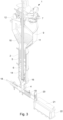
Fig. 2 is a sectional view of the whey draining apparatus shown inFig. 1 . -
Fig. 3 is a perspective sectional view of the whey draining apparatus shown inFig. 1 . -
Fig. 4 is a detailed sectional view of a upright drainage column of the whey draining apparatus shown inFig. 1 . -
Fig. 5 is a detailed sectional view of a pusher of the whey draining apparatus shown inFig. 1 . -
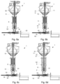
Figs. 6a-6m shows the whey draining apparatus ofFig. 1 during operation of the whey draining apparatus. -
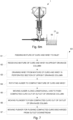
Fig. 7 is a flow chart of a method of draining whey from a mixture of curd and whey using the whey draining apparatus shown inFig. 1 . - Embodiments of the invention will now be described more fully hereinafter with reference to the accompanying drawings, in which some, but not all, embodiments of the invention are shown. The invention may be embodied in many different forms and should not be construed as limited to the embodiments set forth herein.
- With reference to
Figs. 1-3 , an exemplary whey drainingapparatus 1 for producing blocks of cheese is illustrated. The whey drainingapparatus 1 is arranged along a cheese production line to receive a mixture of cheese curd and whey at a location that is downstream from a location at which cheese curd is produced. The whey drainingapparatus 1 is used to drain whey to produce blocks of cheese. The blocks of cheese may be further processed downstream thewhey draining apparatus 1. Examples of types of cheese that may be formed using thewhey draining apparatus 1 include hard cheeses and semi-hard cheeses, such as cheddar cheese, gouda, and mozzarella. Other types of cheese may also be formed using thewhey draining apparatus 1. - The whey draining
apparatus 1 includes anupright drainage column 2 and afeed inlet 3 for a mixture of curd and whey arranged upstream of theupright drainage column 2. Theupright drainage column 2 may be vertical or angled relative to a vertical axis by an angle that is 45 degrees or less. Thefeed inlet 3 is positioned approximate a top end of theupright drainage column 2. Thefeed inlet 3 may be arranged above theupright drainage column 2. Theupright drainage column 2 is configured to receive the mixture of curd and whey downstream thefeed inlet 3 and has anoutlet 4. The compacted curd that is drained of whey is discharged from theupright drainage column 2 through theoutlet 4. Theoutlet 4 is arranged at a lower end of theupright drainage column 2 opposite thefeed inlet 3 and may be defined as part of theupright drainage column 2. Theoutlet 4 may be a lowermost part of theupright drainage column 2. - The
upright drainage column 2 may be formed as a flat steel tube and includes aperforated section 5 for draining whey from the mixture of curd and whey received in theupright drainage column 2. Theperforated section 5 may be formed along an upper portion of theupright drainage column 2. Theperforated section 5 may be formed along a length of theupright drainage column 2 that is approximately one half of a total height of theupright drainage column 2. Theperforated section 5 may be formed along a length of theupright drainage column 2 that is greater than or less than one half of the total height of theupright drainage column 2. - An
auger 6 is arranged along a longitudinal axis L of theupright drainage column 2. Theauger 6 is configured for rotation about the longitudinal axis L to compact the mixture of curd and whey in theupright drainage column 2. Theauger 6 is also configured for linear movement along the longitudinal axis L to push compacted curd that is drained of whey through theoutlet 4 and out of theupright drainage column 2. Using theauger 6 enables rapid compaction of the curd which is pushed below theauger 6 toward theoutlet 4 in contrast to conventional block formers that require a dosing plate below the column. - The
auger 6 may extend through most of a length of theupright drainage column 2. Thewhey draining apparatus 1 may include afirst motor 7 for rotating theauger 6. Asecond motor 8 that is independent of thefirst motor 7 is configured to axially move theauger 6 along the longitudinal axis L. Theauger 6 is configured for bidirectional linear movement through theupright drainage column 2 in that theauger 6 continuously moves up and down during operation. Any suitable drive motors may be used. The motors may include pneumatic or hydraulic drive cylinders. - The
whey draining apparatus 1 includes abuffer tank 9 having a perforatedconical section 10 arranged upstream theupright drainage column 2. The perforatedconical section 10 is formed along a lower portion of thebuffer tank 9. Thebuffer tank 9 has a larger diameter as compared with the diameter of theupright drainage column 2. Thefeed inlet 3 may be formed on thebuffer tank 9 such that the mixture of curd and whey is received in thebuffer tank 9. Thefeed inlet 3 may be formed at a middle portion of thebuffer tank 9 and at an upper end of the perforatedconical section 10. Theauger 6 may extend upwardly through thebuffer tank 9 to themotors buffer tank 9. - The perforated
conical section 10 may be formed as a perforated steel plate and is tapered downwardly toward theupright drainage column 2 arranged below thebuffer tank 9. The perforatedconical section 10 is connected to a top of theupright drainage column 2. In thebuffer tank 9, an amount of whey is drained from the mixture of curd and whey via the perforatedconical section 10. The perforatedconical section 10 of thebuffer tank 9 may form a first draining section and theperforated section 5 of theupright drainage column 2 may form a second draining section downstream the first draining section. - An
agitator 11 is arranged for rotation in thebuffer tank 9 for mixing the curd and whey mixture. Adrive motor 12 rotates theagitator 11 along the perforatedconical section 10. Theagitator 11 has at least one blade that move close to the perforatedconical section 10 to prevent blockage of the holes in the perforatedconical section 10 by the curd particles. - An
overflow conduit 13 is provided on thebuffer tank 9 to control an amount of whey in thebuffer tank 9, such that if an amount of whey exceeds a certain height within thebuffer tank 9, the excess whey will be removed through theoverflow conduit 13. Theoverflow conduit 13 is arranged at an upper portion of thebuffer tank 9. Theoverflow conduit 13 is arranged at a location that is higher relative to thefeed inlet 3. - The
auger 6 hashelical flights 14 that are integrally formed as part of theauger 6 and extend radially outwardly. Thehelical flights 14 may be formed on only a portion of theauger 6. Thehelical flights 14 are configured to rotate and move linearly along theperforated section 5 to compact the curd downwardly below theauger 6 and toward theoutlet 4 of theupright drainage column 2. The amount of rotation and linear movement of theauger 6 is adjustable based on the compression required to produce a desired type of cheese. Thehelical flights 14 are arranged to move close to theperforated section 5 to prevent blockage of the holes of theperforated section 5 by the curd particles. - A
whey removing conduit 15 is provided on an upper portion of theupright drainage column 2 to remove drained whey from theupright drainage column 2 that has been drained via theperforated section 5. Thewhey removing conduit 15 may be arranged to surround theperforated section 5. - A
plunger 16 is arranged to move along the longitudinal axis L inside theauger 6 to push the compacted curd out of theupright drainage column 2. Theplunger 16 is moved by alinear actuator 17 and is configured to descend lower in theupright drainage column 2 relative to theauger 6 such that theplunger 16 is able to push out a last part of the compacted curd from theupright drainage column 2. Thelinear actuator 17 may include a pneumatic or hydraulic cylinder. Theplunger 16 extends through most of the length of theupright drainage column 2 with theplunger 6. Theplunger 16 may extend upwardly through thebuffer tank 9 to thelinear actuator 17 arranged above thebuffer tank 9. - Below the
upright drainage column 2, apusher 18 is arranged proximate theoutlet 4 for pushing compacted curd that is discharged out of theoutlet 4 downstream for further processing. Thepusher 18 may be arranged perpendicular relative to theupright drainage column 2, such that the curd is pushed in a direction that is perpendicular to the direction in which the curd is discharged from theoutlet 4. The compacted curd is received in aperforated tube 19 that is arranged downstream theoutlet 4. Theperforated tube 19 is connected to theupright drainage column 2 and may be arranged perpendicular to theupright drainage column 2. Theperforated tube 19 may be aligned with thepusher 18 and is configured to receive thepusher 18 such that extruded cheese is pushed through theperforated tube 19 by thepusher 18 entering theperforated tube 19. - The
perforated tube 19 is arranged upstream acutting tool 20 that is spaced from theoutlet 4 of theupright drainage column 2. The cuttingtool 20 may be a guillotine knife that is supported at an end of theperforated tube 19 opposite to where theperforated tube 19 is connected to theupright drainage column 2. Ashutter plate 21 is arranged downstream thecutting tool 20 to receive a cut-off portion of the compacted cheese. Amold 22 is arranged downstream theshutter plate 21 and is configured to receive the cut-off portion of the compacted cheese from theshutter plate 21 for molding the cheese block and further downstream processing, such as packaging. - Referring in addition to
Fig. 4 , theauger 6 has ahollow body 30 that extends along the longitudinal axis L of theupright drainage column 2 and a perforatedperipheral surface 31 for draining whey from the mixture of curd and whey to the inside of thehollow body 30. The perforatedperipheral surface 31 may be selectively activated during operation of thewhey draining apparatus 1. - A cooling and
heating channel 32 is formed along a periphery of theupright drainage column 2 for cooling or heating theupright drainage column 2. The cooling andheating 32 is used to maintain operating parameters of thewhey draining apparatus 1 when pressure occurs in thewhey draining apparatus 1. The cooling andheating channel 32 may extend along a lower portion of theupright drainage column 2. - The
plunger 16 includes aconical nose 33 that is pointed downwardly in theupright drainage column 2 and ahollow body 34 that defines a whey-drainingchannel 35. The whey-drainingchannel 35 is arranged along the longitudinal axis L and theconical nose 33 is configured to extend into a taperingportion 36 of theupright drainage column 2 that tapers toward theoutlet 4. Theplunger 16 may be formed to have a radially-extendinglocating tab 37 to position theplunger 16 in theauger 6. The inside of thehollow body 30 of theauger 6 may be in communication with a vacuum that draws the drained whey upwardly and out of theupright drainage column 2. Thehollow bodies auger 6 and theplunger 16 may also be configured to enable cleaning-in-place of the components during a cleaning operation that occurs after the cheese production operation. - Referring in addition to
Fig. 5 , thepusher 18 has a perforatedsection 40 for draining whey and ablocking section 41 for blocking theoutlet 4 of the upright drainage column. Theperforated section 40 and the blockingsection 41 may be formed adjacent to each other along the peripheral surface of thepusher 18. Thepusher 18 is linearly movable between a blocking position in which theblocking section 41 blocks theoutlet 4, prior to extrusion of the cheese, and a draining position in which theoutlet 4 is opened for extrusion of the cheese, and theperforated section 40 is in communication with theoutlet 4 to enable further draining of the compacted curd. - The
pusher 18 is configured to push the compacted curd from theoutlet 4 into theperforated tube 19. Anangular channel 42 is connected between theoutlet 4 and theperforated tube 19 to provide a shear deformation of the compacted curd and remove more of the whey from the compacted curd.Whey removing zones pusher 18 and theperforated tube 19 for removing the drained whey from thewhey draining apparatus 1. A rinsingzone 45 for may be formed on thepusher 18 for cleaning thepusher 18 during a cleaning operation. - Referring now to
Figs. 6a-6m , operation of thewhey draining apparatus 1 is shown for producing blocks of cheese.Fig. 6a shows a first step in which thewhey draining apparatus 1 is filled with whey only.Whey 50 is filled in theupright drainage column 2 and thebuffer tank 9. The cuttingtool 20 is in a closed position and thepusher 18 is in the blocking position in which theblocking section 41 blocks theoutlet 4. Theauger 6 is in an initial position and may start to rotate. -
Fig. 6b shows a second step in which curd sedimentation occurs. Curd particles are added to thewhey draining apparatus 1 to form a mixture of curd andwhey 51 in theupright drainage column 2 and thebuffer tank 9. The perforatedconical section 10 of thebuffer tank 9 and theperforated section 5 of theupright drainage column 2 are activated to drain whey from the mixture of curd andwhey 51. Theauger 6 continues to rotate and compactedcurd 52 is pushed down by theauger 6 toward theoutlet 4 of theupright drainage column 2. Thepusher 18 remains in the blocking position such that theoutlet 4 is closed. -
Fig. 6c shows a third step in which draining by thepusher 18 and theauger 6 occurs. Thepusher 18 is moved to the draining position in which theperforated section 40 is in communication with theoutlet 4 for further draining whey from the compactedcurd 52. The drained whey is removed from thewhey draining apparatus 1 via thewhey removing zone 43 of thepusher 18. The perforatedperipheral surface 31 of theauger 6 is activated for draining whey to the inside of theauger 6 to be drawn upwardly and out of thewhey draining apparatus 1 by a vacuum. -
Fig. 6d shows a fourth step in which the cheese is compacted. Theauger 6 starts to move upwardly in theupright drainage column 2, such that morecompacted curd 52 is formed below theauger 6. Theagitator 11 remains active inFigs. 6b-6d . Whey draining continues via the perforatedperipheral surface 31 of theauger 6, the perforatedconical section 10 of thebuffer tank 9, theperforated section 5 of theupright drainage column 2, and theperforated section 40 of thepusher 18. -
Fig. 6e shows a fifth step that occurs prior to extrusion of the cheese. Thepusher 18 is moved out of the blocking position to open theoutlet 4 for extrusion of the cheese. Theauger 6 is moved upwardly and rotation of theauger 6 is stopped. Whey draining continues via the perforatedperipheral surface 31 of theauger 6, the perforatedconical section 10 of thebuffer tank 9, and theperforated section 5 of theupright drainage column 2. -
Fig. 6f shows a sixth step in which compactedcurd 53 that has been extruded from theupright drainage column 2 enters theperforated tube 19. Theauger 6 returns to its initial position (shown inFig. 6a ) and rotation of theauger 6 is stopped. Theauger 6 is moved downwardly from its previous position shown inFig. 6e to move the compactedcurd 52 in theupright drainage column 2 out of theoutlet 4. Theperforated tube 19 is activated for draining. Whey draining also occurs via the perforatedconical section 10 of thebuffer tank 9 and theperforated section 5 of theupright drainage column 2. Theagitator 11 remains active in the steps shown inFigs. 6e and 6f . -
Fig. 6G shows a seventh step in which theauger 6 is moved upwardly to a dosing position. Theauger 6 may be continuously moved upwardly and downwardly, and the movement of theauger 6 may correspond to the desired type of cheese to be produced. The speed of rotation of theauger 6 and the linear movement of theauger 6 may correspond to each other. The cuttingtool 20 remains in a closed position. -
Fig. 6h shows an eighth step in which thecutting tool 20 is opened in preparation to cut the extrudedcheese 53 and form a cut-off block of cheese. In both of the steps shown inFigs. 6G and 6h , whey draining continues via the perforatedconical section 10 of thebuffer tank 9, theperforated section 5 of theupright drainage column 2, and theperforated tube 19. Theagitator 11 also remains active. -
Fig. 6i shows a ninth step in which thecutting tool 20 is closed to cut the extrudedcheese 53. Theshutter plate 21 is arranged downstream thecutting tool 20 and is opened to receive the cut-off block ofcheese 54. The cut-off block ofcheese 54 is then dropped into themold 22 for further downstream processing, such as packaging. Whey draining via the perforatedperipheral surface 31 of theauger 6 is activated. Whey draining continues via the perforatedconical section 10 of thebuffer tank 9 and theperforated section 5 of theupright drainage column 2. Theagitator 11 also remains active. -
Fig. 6j shows a tenth step in which all of the whey is removed from theupright drainage column 2. Theauger 6 is moved downwardly into an emptying position to push a remaining amount of the compactedcurd 52 out of theupright drainage column 2. The cuttingtool 20 is in an open position. The agitator and draining sections are inactive. -
Fig. 6k shows an eleventh step in which theplunger 16 is activated and descends lower in theupright drainage column 2 relative to theauger 6 to push the remaining amount of the compactedcurd 55 out of theupright drainage column 2. The remaining amount of the compactedcurd 55 is pushed into theperforated tube 19. The cuttingtool 20 is in the open position. -
Fig. 6l shows a twelfth step in which theplunger 16 is moved upwardly to return to its initial position and thecutting tool 20 remains in the open position. Thepusher 18 is activated to push a final block ofcheese 56 out of theperforated tube 19 and downstream for further processing. -
Fig. 6m shows a thirteenth step in which theshutter 21 is opened and the final block ofcheese 56 is dropped into themold 22. After the final block ofcheese 56 is removed from thewhey draining apparatus 1, a clean-in-place system may be activated and thewhey draining apparatus 1 may be cleaned to remove any excess cheese in thewhey draining apparatus 1. - Referring now to
Fig. 7 , amethod 60 of draining whey using thewhey draining apparatus 1 is shown. Themethod 60 includes astep 61 of feeding the mixture of curd andwhey 51 to thefeed inlet 3 of thewhey draining apparatus 1 and step 62 includes receiving the mixture of curd andwhey 51 in theupright drainage column 2.Step 63 includes draining whey from the mixture of curd andwhey 51 in theperforated section 5 of theupright drainage column 2.Step 64 of themethod 60 includes rotating theauger 6 around the longitudinal axis L of theupright drainage column 2 to compact the mixture of curd andwhey 51 in theupright drainage column 2.Step 65 of themethod 60 includes moving theauger 6 along the longitudinal axis L to push compactedcurd 52 that is drained of whey through theoutlet 4 out of theupright drainage column 2. -
Step 66 of themethod 60 includes moving theplunger 16 along the longitudinal axis L inside theauger 6 to push the compactedcurd 52 out of theupright drainage column 2.Step 67 of themethod 60 includes moving thepusher 18 arranged proximate theoutlet 4 for pushing the compactedcurd 52 discharged from theoutlet 4 downstream. - While the invention has been described with reference to one or more preferred features, which features have been set forth in considerable detail for the purposes of making a complete disclosure of the invention, such features are merely exemplary and are not intended to be limiting or represent an exhaustive enumeration of all aspects of the invention. The scope of the invention, therefore, shall be defined solely by the following claims. Further, it will be apparent to those of skill in the art that numerous changes may be made in such details without departing from the spirit and the principles of the invention.
Claims (15)
- A whey draining apparatus (1) for the production of blocks of cheese mass, the whey draining apparatus (1) comprising:a feed inlet (3) for a mixture of curd and whey (51); andan upright drainage column (2) configured to receive the mixture of curd and whey (51), the upright drainage column (2) having an outlet (4) and a perforated section (5) for draining whey from the mixture of curd and whey (51),characterized byan auger (6) arranged along a longitudinal axis (L) of the upright drainage column (2), the auger (6) configured for rotation about the longitudinal axis (L) to compact the mixture of curd and whey (51) in the upright drainage column (2), the auger (6) configured for movement along the longitudinal axis (L) to push compacted curd (52) that is drained of whey through the outlet (4) and out of the upright drainage column (2).
- The whey draining apparatus (1) according to claim 1, comprising a buffer tank (9) having a perforated conical section (10) arranged upstream the upright drainage column (2).
- The whey draining apparatus (1) according to claim 2, comprising an agitator (11) that rotates along the perforated conical section (8) in the buffer tank (7).
- The whey draining apparatus (1) according to any preceding claim, wherein the auger (6) has helical flights (14) arranged to move along the perforated section (5) of the upright drainage column (2).
- The whey draining apparatus (1) according to any preceding claim, wherein the auger (6) has a hollow body (30) and a perforated peripheral surface (31) for draining whey from the mixture of curd and whey (51) to the inside of the hollow body (30).
- The whey draining apparatus (1) according to any preceding claim, comprising a plunger (16) arranged to move along the longitudinal axis (L) inside the auger (6) to push the compacted curd (52) out of the upright drainage column (2), wherein the plunger (16) descends lower in the upright drainage column (2) relative to the auger (6).
- The whey draining apparatus (1) according to claim 6, wherein the plunger (16) has a hollow body (34) defining a whey-draining channel (35).
- The whey draining apparatus (1) according to any preceding claim, comprising a pusher (18) arranged proximate the outlet (4) for pushing compacted curd (52) that is discharged from the outlet (4) downstream, wherein the pusher (18) has a perforated section (40) for draining whey and a blocking section (41) for blocking the outlet (4) of the upright drainage column (2).
- The whey draining apparatus (1) according to claim 8, wherein the pusher (18) is arranged perpendicularly relative to the upright drainage column (2).
- The whey draining apparatus (1) according to claim 8 or 9, comprising a perforated tube (19) configured to receive the compacted curd (52) from the outlet (4) and arranged downstream the pusher (18).
- The whey draining apparatus (1) according to claim 10, comprising an angular channel (42) connected between the outlet (4) and the perforated tube (19).
- The whey draining apparatus (1) according to any preceding claim, comprising a first motor (7) that rotates the auger (6) and a second motor (8) that axially moves the auger (6).
- A method (60) of draining whey from a mixture of curd and whey (51), comprising:feeding (61) the mixture of curd and whey (51) to a feed inlet (3);receiving (62) the mixture of curd and whey (51) in an upright drainage column (2) arranged downstream the feed inlet (3); anddraining (63) whey from the mixture of curd and whey (51) in a perforated section (5) of the upright drainage column (2),characterized byrotating (64) an auger (6) around a longitudinal axis (L) of the upright drainage column (2) to compact the mixture of curd and whey (51) in the upright drainage column (2); andmoving (65) the auger (6) along the longitudinal axis (L) to push compacted curd (52) that is drained of whey through an outlet (4) out of the upright drainage column (2).
- The method (60) according to claim 13, comprising moving (66) a plunger (16) along the longitudinal axis (L) inside the auger (6) to push the compacted curd (52) out of the upright drainage column (2), wherein the plunger (16) is configured to descend lower in the upright drainage column (2) relative to the auger (6).
- The method (60) according to claim 13 or 14, comprising moving (67) a pusher (18) arranged proximate the outlet (4) for pushing the compacted curd (52) discharged from the outlet (4) downstream, wherein the pusher (18) has a perforated section (40) and a blocking section (41).
Priority Applications (1)
| Application Number | Priority Date | Filing Date | Title |
|---|---|---|---|
| EP21211442.5A EP4186358B1 (en) | 2021-11-30 | 2021-11-30 | Whey draining apparatus and method |
Applications Claiming Priority (1)
| Application Number | Priority Date | Filing Date | Title |
|---|---|---|---|
| EP21211442.5A EP4186358B1 (en) | 2021-11-30 | 2021-11-30 | Whey draining apparatus and method |
Publications (2)
| Publication Number | Publication Date |
|---|---|
| EP4186358A1 true EP4186358A1 (en) | 2023-05-31 |
| EP4186358B1 EP4186358B1 (en) | 2026-04-22 |
Family
ID=78819903
Family Applications (1)
| Application Number | Title | Priority Date | Filing Date |
|---|---|---|---|
| EP21211442.5A Active EP4186358B1 (en) | 2021-11-30 | 2021-11-30 | Whey draining apparatus and method |
Country Status (1)
| Country | Link |
|---|---|
| EP (1) | EP4186358B1 (en) |
Citations (2)
| Publication number | Priority date | Publication date | Assignee | Title |
|---|---|---|---|---|
| US3606683A (en) * | 1967-03-15 | 1971-09-21 | Bel La Vache Qui Rit Fromage | Method and apparatus for continuously separating curd and whey |
| CA2365273A1 (en) * | 1999-03-04 | 2000-09-08 | Carlisle Process Systems Limited | A cheese tower incorporating a pressurised curd inlet |
-
2021
- 2021-11-30 EP EP21211442.5A patent/EP4186358B1/en active Active
Patent Citations (2)
| Publication number | Priority date | Publication date | Assignee | Title |
|---|---|---|---|---|
| US3606683A (en) * | 1967-03-15 | 1971-09-21 | Bel La Vache Qui Rit Fromage | Method and apparatus for continuously separating curd and whey |
| CA2365273A1 (en) * | 1999-03-04 | 2000-09-08 | Carlisle Process Systems Limited | A cheese tower incorporating a pressurised curd inlet |
Also Published As
| Publication number | Publication date |
|---|---|
| EP4186358B1 (en) | 2026-04-22 |
Similar Documents
| Publication | Publication Date | Title |
|---|---|---|
| CN102837412A (en) | Equipment for processing plastic bottle cap by extrusion compression molding | |
| US3891783A (en) | Method and apparatus for cheese manufacture | |
| US6337099B2 (en) | Method for producing blocks of cheese | |
| EP4186358B1 (en) | Whey draining apparatus and method | |
| WO2000033643A9 (en) | Apparatus and method for making cheese | |
| EP0739160B1 (en) | Green cheese handling system | |
| US6180153B1 (en) | Method and apparatus for cheese block forming with vacuum separated tower sections | |
| US20110014311A1 (en) | Method and system for making extruded portions of cheese | |
| US3543403A (en) | Cheese production | |
| US7758905B2 (en) | Method and system for making extruded portions of cheese | |
| EP1592308B1 (en) | Continuous curding process | |
| KR100336704B1 (en) | Method and apparatus for manufacturing molded plastic product | |
| EP3166394B1 (en) | Method and arrangement for filling of cheese curd in moulds | |
| CN117532804A (en) | Cheese bar production equipment and production process thereof | |
| AU2004212211B2 (en) | Continuous curding process | |
| NZ248758A (en) | Cheese mould filling; opposed plate knives sever curd blocks from curd mass at bottom of drain tube, the curd blocks being delivered to an intermediate mould before the cheese mould | |
| EP3673740B1 (en) | Cheese block former comprising a tower screen relief step | |
| EP3673739B1 (en) | Tower screen dual surface finish | |
| JPH08112056A (en) | Production of multilayer-coated food | |
| HU193295B (en) | Cheese curd press | |
| EP4023058A1 (en) | Apparatus and method for draining and forming curd | |
| SU1364254A1 (en) | Installation for continuous moulding of cheese | |
| HU205531B (en) | Apparatus for producing cheeses of continuous operation | |
| ITUD940113A1 (en) | AUTOMATIC CHEESE PRODUCTION SYSTEM WITH CHEESE MAKING REACTOR AND RELATED PROCEDURE | |
| JPH0856601A (en) | Device for continuously and automatically producing bean curd |
Legal Events
| Date | Code | Title | Description |
|---|---|---|---|
| PUAI | Public reference made under article 153(3) epc to a published international application that has entered the european phase |
Free format text: ORIGINAL CODE: 0009012 |
|
| STAA | Information on the status of an ep patent application or granted ep patent |
Free format text: STATUS: THE APPLICATION HAS BEEN PUBLISHED |
|
| AK | Designated contracting states |
Kind code of ref document: A1 Designated state(s): AL AT BE BG CH CY CZ DE DK EE ES FI FR GB GR HR HU IE IS IT LI LT LU LV MC MK MT NL NO PL PT RO RS SE SI SK SM TR |
|
| STAA | Information on the status of an ep patent application or granted ep patent |
Free format text: STATUS: REQUEST FOR EXAMINATION WAS MADE |
|
| 17P | Request for examination filed |
Effective date: 20231130 |
|
| RBV | Designated contracting states (corrected) |
Designated state(s): AL AT BE BG CH CY CZ DE DK EE ES FI FR GB GR HR HU IE IS IT LI LT LU LV MC MK MT NL NO PL PT RO RS SE SI SK SM TR |
|
| GRAP | Despatch of communication of intention to grant a patent |
Free format text: ORIGINAL CODE: EPIDOSNIGR1 |
|
| STAA | Information on the status of an ep patent application or granted ep patent |
Free format text: STATUS: GRANT OF PATENT IS INTENDED |
|
| RIC1 | Information provided on ipc code assigned before grant |
Ipc: A01J 25/11 20060101AFI20251112BHEP |
|
| INTG | Intention to grant announced |
Effective date: 20251119 |
|
| GRAS | Grant fee paid |
Free format text: ORIGINAL CODE: EPIDOSNIGR3 |
|
| GRAA | (expected) grant |
Free format text: ORIGINAL CODE: 0009210 |
|
| STAA | Information on the status of an ep patent application or granted ep patent |
Free format text: STATUS: THE PATENT HAS BEEN GRANTED |
|
| AK | Designated contracting states |
Kind code of ref document: B1 Designated state(s): AL AT BE BG CH CY CZ DE DK EE ES FI FR GB GR HR HU IE IS IT LI LT LU LV MC MK MT NL NO PL PT RO RS SE SI SK SM TR |
|
| REG | Reference to a national code |
Ref country code: CH Ref legal event code: F10 Free format text: ST27 STATUS EVENT CODE: U-0-0-F10-F00 (AS PROVIDED BY THE NATIONAL OFFICE) Effective date: 20260422 Ref country code: GB Ref legal event code: FG4D |
|
| REG | Reference to a national code |
Ref country code: DE Ref legal event code: R096 Ref document number: 602021052485 Country of ref document: DE |