EP4186329B1 - Verfahren, vorrichtung und computerprogramm produkt zur konfiguration von sidelink-drx - Google Patents
Verfahren, vorrichtung und computerprogramm produkt zur konfiguration von sidelink-drx Download PDFInfo
- Publication number
- EP4186329B1 EP4186329B1 EP21941047.9A EP21941047A EP4186329B1 EP 4186329 B1 EP4186329 B1 EP 4186329B1 EP 21941047 A EP21941047 A EP 21941047A EP 4186329 B1 EP4186329 B1 EP 4186329B1
- Authority
- EP
- European Patent Office
- Prior art keywords
- drx configuration
- drx
- timer
- message
- another implementation
- Prior art date
- Legal status (The legal status is an assumption and is not a legal conclusion. Google has not performed a legal analysis and makes no representation as to the accuracy of the status listed.)
- Active
Links
Images


Classifications
-
- H—ELECTRICITY
- H04—ELECTRIC COMMUNICATION TECHNIQUE
- H04W—WIRELESS COMMUNICATION NETWORKS
- H04W72/00—Local resource management
- H04W72/20—Control channels or signalling for resource management
- H04W72/25—Control channels or signalling for resource management between terminals via a wireless link, e.g. sidelink
-
- H—ELECTRICITY
- H04—ELECTRIC COMMUNICATION TECHNIQUE
- H04W—WIRELESS COMMUNICATION NETWORKS
- H04W28/00—Network traffic management; Network resource management
- H04W28/16—Central resource management; Negotiation of resources or communication parameters, e.g. negotiating bandwidth or QoS [Quality of Service]
- H04W28/24—Negotiating SLA [Service Level Agreement]; Negotiating QoS [Quality of Service]
-
- H—ELECTRICITY
- H04—ELECTRIC COMMUNICATION TECHNIQUE
- H04W—WIRELESS COMMUNICATION NETWORKS
- H04W52/00—Power management, e.g. Transmission Power Control [TPC] or power classes
- H04W52/02—Power saving arrangements
- H04W52/0209—Power saving arrangements in terminal devices
- H04W52/0212—Power saving arrangements in terminal devices managed by the network, e.g. network or access point is leader and terminal is follower
- H04W52/0216—Power saving arrangements in terminal devices managed by the network, e.g. network or access point is leader and terminal is follower using a pre-established activity schedule, e.g. traffic indication frame
-
- H—ELECTRICITY
- H04—ELECTRIC COMMUNICATION TECHNIQUE
- H04W—WIRELESS COMMUNICATION NETWORKS
- H04W72/00—Local resource management
- H04W72/04—Wireless resource allocation
- H04W72/044—Wireless resource allocation based on the type of the allocated resource
- H04W72/0446—Resources in time domain, e.g. slots or frames
-
- H—ELECTRICITY
- H04—ELECTRIC COMMUNICATION TECHNIQUE
- H04W—WIRELESS COMMUNICATION NETWORKS
- H04W76/00—Connection management
- H04W76/20—Manipulation of established connections
- H04W76/28—Discontinuous transmission [DTX]; Discontinuous reception [DRX]
-
- H—ELECTRICITY
- H04—ELECTRIC COMMUNICATION TECHNIQUE
- H04W—WIRELESS COMMUNICATION NETWORKS
- H04W8/00—Network data management
- H04W8/22—Processing or transfer of terminal data, e.g. status or physical capabilities
-
- H—ELECTRICITY
- H04—ELECTRIC COMMUNICATION TECHNIQUE
- H04W—WIRELESS COMMUNICATION NETWORKS
- H04W92/00—Interfaces specially adapted for wireless communication networks
- H04W92/16—Interfaces between hierarchically similar devices
- H04W92/18—Interfaces between hierarchically similar devices between terminal devices
-
- H—ELECTRICITY
- H04—ELECTRIC COMMUNICATION TECHNIQUE
- H04W—WIRELESS COMMUNICATION NETWORKS
- H04W76/00—Connection management
- H04W76/20—Manipulation of established connections
- H04W76/23—Manipulation of direct-mode connections
-
- Y—GENERAL TAGGING OF NEW TECHNOLOGICAL DEVELOPMENTS; GENERAL TAGGING OF CROSS-SECTIONAL TECHNOLOGIES SPANNING OVER SEVERAL SECTIONS OF THE IPC; TECHNICAL SUBJECTS COVERED BY FORMER USPC CROSS-REFERENCE ART COLLECTIONS [XRACs] AND DIGESTS
- Y02—TECHNOLOGIES OR APPLICATIONS FOR MITIGATION OR ADAPTATION AGAINST CLIMATE CHANGE
- Y02D—CLIMATE CHANGE MITIGATION TECHNOLOGIES IN INFORMATION AND COMMUNICATION TECHNOLOGIES [ICT], I.E. INFORMATION AND COMMUNICATION TECHNOLOGIES AIMING AT THE REDUCTION OF THEIR OWN ENERGY USE
- Y02D30/00—Reducing energy consumption in communication networks
- Y02D30/70—Reducing energy consumption in communication networks in wireless communication networks
Definitions
- the present disclosure is directed generally to wireless communications. Particularly, the present disclosure relates to methods, devices, and systems for configuring a sidelink discontinuous reception (DRX).
- DRX sidelink discontinuous reception
- UEs in a wireless network may communicate data with one another via direct sidelink (SL) communication channels without the data being relayed by any wireless access network nodes.
- SL direct sidelink
- communication resource allocation and configuration for one communication terminal may involve another communication terminal in addition to a base station. It is critical to provide a resource allocation, provisioning, and release mechanism to enable low-power and efficient use of sidelink communication resources.
- the present disclosure describes various embodiments for configuring a sidelink discontinuous reception (DRX), addressing one or more problems/issues and improving the efficiency of the sidelink DRX mechanism.
- ZTE "Discussion on PC5 DRX” (3GPP DRAFT; R2-1704634 ), LENOVO ET AL: "Discussion on SL DRX for unicast” (3GPP DRAFT; R2-2103401 ), and HUAWEI ET AL: "Consideration on the sidelink DRX for unicast, groupcast and broadcast” (3GPP DRAFT; R2-2009413 ) are related prior art.
- the present disclosure describes a method for wireless communication as defined by independent claim 1.
- an apparatus for wireless communication includes a memory storing instructions and a processing circuitry in communication with the memory.
- the processing circuitry executes the instructions, the processing circuitry is configured to carry out the above methods.
- a computer-readable medium comprising instructions which, when executed by a computer, cause the computer to carry out the above methods.
- terms, such as “a”, “an”, or “the”, again, may be understood to convey a singular usage or to convey a plural usage, depending at least in part upon context.
- the term “based on” or “determined by” may be understood as not necessarily intended to convey an exclusive set of factors and may, instead, allow for existence of additional factors not necessarily expressly described, again, depending at least in part on context.
- the present disclosure describes various methods and devices for configuring a sidelink discontinuous reception (DRX).
- DRX sidelink discontinuous reception
- New generation (NG) mobile communication system are moving the world toward an increasingly connected and networked society.
- High-speed and low-latency wireless communications rely on efficient network resource management and allocation between user equipment and wireless access network nodes (including but not limited to wireless base stations).
- a new generation network is expected to provide high speed, low latency and ultra-reliable communication capabilities and fulfill the requirements from different industries and users.
- a vehicle network refers to a network system for wireless communication and information exchange among vehicles, pedestrians, roadside equipments, and the Internet and other data networks in accordance with various communication protocols and data exchange standards.
- Vehicle network communication helps improve road safety, enhance traffic efficiency, and provide broadband mobile data access and inter-network node data exchanges.
- the vehicle network communication may be categorized into various types as differentiated according to the communication endpoints, including but not limited to vehicle-to-vehicle (V2V) communication, vehicle-to-infrastructure/vehicle-to-network (V2I/V2N) communication, and vehicle-to-pedestrian (V2P) communication. These types of communication are referred to, collectively, as vehicle-to-everything (V2X) communication.
- V2X vehicle-to-everything
- Such a vehicle network may heavily rely on sidelink communication between the terminal devices or user equipments (UEs) in the network.
- Sidelink communication refers to a direct wireless information exchange between UEs.
- Sidelink (SL) is a unilateral wireless communication service, i.e., the communication between the communication terminals or user equipment (UE).
- Vehicle networking refers to a large scale system for wireless communication and information exchange among vehicles, pedestrians, roadside equipment, and internet in accordance with agreed communication protocols and data exchange standards. The vehicle networking communications enable the vehicles to gain driving safety, improve traffic efficiency, and acquire convenience or entertainment information.
- the vehicle networking communication may be categorized into three types as per the objects of wireless communication: the communication between vehicles, i.e., vehicle-to-vehicle (V2V); the communication between vehicles and roadside equipment/network infrastructures, i.e., vehicle-to-infrastructure/vehicle-to-network (V2I/V2N); and the communication between vehicles and pedestrians, i.e., vehicle-to-pedestrian (V2P).
- V2X vehicle-to-everything
- the sidelink based V2X communication between user equipment is one of the manners to implement the V2X standard, in which traffic data is directly transmitted from a source UE to a destination UE via an air interface without forwarding by the base station and the core network.
- This V2X communication is referred to as PC5-based V2X communication or V2X sidelink communication.
- the advanced V2X services include vehicle platooning, extended sensors, advanced driving (semi-automated driving and full-automated driving), and remote driving.
- the desired performance requirements may include: supporting data packet with the size of 50 to 12000 bytes, transmission rate with 2 to 50 messages per second, the maximum end-to-end delay of 3 to 500 milliseconds, reliability of 90% to 99.999%, data rate of 0.5 to 1000 Mbps, as well as transmission range of 50 to 1000 meters.
- V2X subsystem based on sidelink communication technology is illustrated as part of FIG. 1 and may be referred to as, for example, PC5-based V2X communication or V2X sidelink communication.
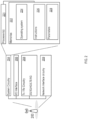
- FIG. 1 shows an example system diagram of a wireless access communication network 100 including UEs 102, 124, and 126 as well as a wireless access network node (WANN) 104.
- WANN wireless access network node
- Each of the UEs 102, 124, and 126 may include but is not limited to a mobile phone, a smartphone, a tablet, a laptop computer, a vehicle on-board communication equipment, a roadside communication equipment, a sensor device, a smart appliance (such as a television, a refrigerator, and an oven), or other devices that are capable of communicating wirelessly over a network.
- the UEs may indirectly communicate with each other via the WANN 104 or directly via sidelinks.
- each of the UEs such as UE 102 may include transceiver circuitry 106 coupled to an antenna 108 to effectuate wireless communication with the WANN 104 or with another UE such as UE 124 or 126.
- the transceiver circuitry 106 may also be coupled to a processor 110, which may also be coupled to a memory 112 or other storage devices.
- the memory 112 may store therein computer instructions or code which, when read and executed by the processor 110, cause the processor 110 to implement various ones of the methods for sidelink resource allocation/configuration/release and data transmission/reception described herein.
- the WANN 104 may include a base station or other wireless network access points capable of communicating wirelessly over a network with one or more UEs and communicating with a core network.
- the WANN 104 may be implemented in the form of a 4G LTE base station, a 5G NR base station, a 5G central-unit base station, or a 5G distributed-unit base station. Each type of these WANNs may be configured to perform a corresponding set of wireless network functions.
- the WANN 104 may include transceiver circuitry 114 coupled to an antenna 116, which may include an antenna tower 118 in various forms, to effectuate wireless communications with the UEs 102, 124, and 126.
- the transceiver circuitry 114 may be coupled to one or more processors 120, which may further be coupled to a memory 122 or other storage devices.
- the memory 122 may store therein instructions or code that, when read and executed by the processor 120, cause the processor 120 to implement various functions. These functions, for example, may include those related to the sidelink resource allocation, configuration, provisioning and releases described below.
- each WANN may serve one or more UEs. While the UEs 102, 124, and 126 of Figure 1 are shown as being served within one serving cell, they may alternatively be served by different cells and/or by no cell. While various embodiments of sidelink communication below are discussed in the context of the particular example cellular wireless communication access network 100, the underlying principle apply to other types of wireless communication networks.
- Sidelink communication among the various UEs of FIG. 1 may support co-existence of various distinct communication cast types including unicast, group-cast (or multicast), and broadcast.
- the cast type may be referred as a cast mode.
- the UEs deployed in the access network 100 may be required to perform exhaustive monitoring of a large range of sidelink wireless resources in either unicast, group-cast, or broadcast mode, thereby incurring a large power consumption. Such power consumption may be at an unacceptably high level for some low power UEs.
- the UEs monitor the sidelink signals within the entire range of sidelink receive resource pool, which can result in large power consumption and reduced efficiency.
- One of the objectives of the present disclosure is to reduce the power consumption of the sidelink communication while meeting the time delay requirements.
- SL DRX discontinuous reception
- DTX discontinuous transmission
- DRX configuration information may include, for example, a delay (e.g., sl-drx-SlotOffset) before starting an on duration timer (e.g., sl-drx-onDurationTimer); the on duration timer (e.g., sl-drx-onDurationTimer), which is the duration at the beginning of an SL DRX cycle; a subtrame where the SL DRX cycle starts (sl-drx-StartOffset); and the SL DRX cycle (sl-drx-Cycle).
- a delay e.g., sl-drx-SlotOffset
- an on duration timer e.g., sl-drx-onDurationTimer
- the on duration timer e.g., sl-drx-onDurationTimer
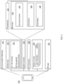
- FIG. 2 shows an example of electronic device 200 to implement a network base station (e.g., a radio access network node), a core network (CN), and/or an operation and maintenance (OAM).
- the example electronic device 200 may include radio transmitting/receiving (Tx/Rx) circuitry 208 to transmit/receive communication with UEs and/or other base stations.
- the electronic device 200 may also include network interface circuitry 209 to communicate the base station with other base stations and/or a core network, e.g., optical or wireline interconnects, Ethernet, and/or other data transmission mediums/protocols.
- the electronic device 200 may optionally include an input/output (I/O) interface 206 to communicate with an operator or the like.
- I/O input/output
- the electronic device 200 may also include system circuitry 204.
- System circuitry 204 may include processor(s) 221 and/or memory 222.
- Memory 222 may include an operating system 224, instructions 226, and parameters 228.
- Instructions 226 may be configured for the one or more of the processors 221 to perform the functions of the network node.
- the parameters 228 may include parameters to support execution of the instructions 226. For example, parameters may include network protocol settings, bandwidth parameters, radio frequency mapping assignments, and/or other parameters.
- FIG. 3 shows an example of an electronic device to implement a terminal device 300 (for example, a user equipment (UE)).
- the UE 300 may be a mobile device, for example, a smart phone or a mobile communication module disposed in a vehicle.
- the UE 300 may include a portion or all of the following: communication interfaces 302, a system circuitry 304, an input/output interfaces (I/O) 306, a display circuitry 308, and a storage 309.
- the display circuitry may include a user interface 310.
- the system circuitry 304 may include any combination of hardware, software, firmware, or other logic/circuitry.
- the system circuitry 304 may be implemented, for example, with one or more systems on a chip (SoC), application specific integrated circuits (ASIC), discrete analog and digital circuits, and other circuitry.
- SoC systems on a chip
- ASIC application specific integrated circuits
- the system circuitry 304 may be a part of the implementation of any desired functionality in the UE 300.
- the system circuitry 304 may include logic that facilitates, as examples, decoding and playing music and video, e.g., MP3, MP4, MPEG, AVI, FLAC, AC3, or WAV decoding and playback; running applications; accepting user inputs; saving and retrieving application data; establishing, maintaining, and terminating cellular phone calls or data connections for, as one example, internet connectivity; establishing, maintaining, and terminating wireless network connections, Bluetooth connections, or other connections; and displaying relevant information on the user interface 310.
- the user interface 310 and the inputs/output (I/O) interfaces 306 may include a graphical user interface, touch sensitive display, haptic feedback or other haptic output, voice or facial recognition inputs, buttons, switches, speakers and other user interface elements.
- I/O interfaces 306 may include microphones, video and still image cameras, temperature sensors, vibration sensors, rotation and orientation sensors, headset and microphone input / output jacks, Universal Serial Bus (USB) connectors, memory card slots, radiation sensors (e.g., IR sensors), and other types of inputs.
- USB Universal Serial Bus
- the communication interfaces 302 may include a Radio Frequency (RF) transmit (Tx) and receive (Rx) circuitry 316 which handles transmission and reception of signals through one or more antennas 314.
- the communication interface 302 may include one or more transceivers.
- the transceivers may be wireless transceivers that include modulation / demodulation circuitry, digital to analog converters (DACs), shaping tables, analog to digital converters (ADCs), filters, waveform shapers, filters, pre-amplifiers, power amplifiers and/or other logic for transmitting and receiving through one or more antennas, or (for some devices) through a physical (e.g., wireline) medium.
- the transmitted and received signals may adhere to any of a diverse array of formats, protocols, modulations (e.g., QPSK, 16-QAM, 64-QAM, or 256-QAM), frequency channels, bit rates, and encodings.
- the communication interfaces 302 may include transceivers that support transmission and reception under the 2G, 3G, BT, WiFi, Universal Mobile Telecommunications System (UMTS), High Speed Packet Access (HSPA)+, 4G / Long Term Evolution (LTE) , and 5G standards.
- UMTS Universal Mobile Telecommunications System
- HSPA High Speed Packet Access
- LTE Long Term Evolution
- 5G 5G
- the system circuitry 304 may include one or more processors 321 and memories 322.
- the memory 322 stores, for example, an operating system 324, instructions 326, and parameters 328.
- the processor 321 is configured to execute the instructions 326 to carry out desired functionality for the UE 300.
- the parameters 328 may provide and specify configuration and operating options for the instructions 326.
- the memory 322 may also store any BT, WiFi, 3G, 4G, 5G or other data that the UE 300 will send, or has received, through the communication interfaces 302.
- a system power for the UE 300 may be supplied by a power storage device, such as a battery or a transformer.
- the present disclosure describes various embodiments for configuring a sidelink discontinuous reception (DRX), which may be implemented, partly or totally, on one or more electronic device 200 and/or one or more terminal device 300 described above in FIGS. 2-3 .
- DRX sidelink discontinuous reception
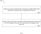
- a method 400 for wireless communication includes configuring a sidelink discontinuous reception (DRX).
- the method 400 may include a portion or all of the following steps: step 410, obtaining, by a first user equipment (UE), a discontinuous reception (DRX) profile information of a second UE from an upper layer of the first UE; and step 420, sending, by the first UE based on the obtained DRX profile information of the second UE, a PC5 message to the second UE or receiving the PC5 message from the second UE.
- UE user equipment
- DRX discontinuous reception
- the obtained DRX profile information of the second UE indicates at least one of the following: the second UE supports the DRX; the second UE does not support the DRX; or it is unknown whether the second UE supports the DRX.
- the method 400 may further include obtaining, by the first UE, a DRX configuration from a network or pre-configuration, the DRX configuration comprising a set of DRX parameter, wherein the set of DRX parameters comprises at least one of the following: a DRX cycle; a slot offset; an on-duration timer; or a start offset.
- the DRX profile information of the second UE is associated with at least one of the following: a destination layer-2 ID information; or a cast type related information.
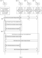
- FIG. 5 shows various embodiments of the layer-2 link establishment procedure for unicast mode of V2X communication over a PC5 reference point.
- first UE There may be a first UE (UE-1, 501), a second UE (UE-2, 502), a third UE (UE-3, 503), and a fourth UE (UE-4, 504). In some embodiments, there may be more than four UEs or fewer than four UEs. In some embodiments, any other UE, except the first UE, may be referred as a "second UE". In some embodiments, the first UE may be referred as a transmitting (TX) UE, and any other UE except the first UE may be referred as a receiving (RX) UE.
- TX transmitting
- RX receiving
- the UE(s) determines the destination Layer-2 ID for signaling reception for PC5 unicast link establishment.
- the V2X application layer in UE-1 provides application information for PC5 unicast communication.
- the application information includes the V2X service type(s) and the initiating UE's Application Layer ID.
- the target UE's Application Layer ID may be included in the application information.
- the V2X application layer in UE-1 may provide V2X Application Requirements for this unicast communication.
- the UE If UE-1 decides to reuse the existing PC5 unicast link, the UE triggers Layer-2 link modification procedure.
- the UE-1 may send a direct communication request to other UE via a broadcast mode.
- Various embodiments include a UE oriented layer-2 link establishment, as shown in 580 in FIG. 5 .
- a target UE for example, the UE-2, may send a direct communication accept to the UE-1 in a unicast mode.
- step 552 after the UE-1 receives the direct communication accept from the UE-2, the UE-1 and the UE-2 may establish and communicate V2X service data over unicast link.
- Various embodiments include a V2X service oriented layer-2 link establishment, as shown in 590 in FIG. 5 .
- a target UE for example, the UE-2, may send a direct communication accept to the UE-1 in a unicast mode.
- another target UE for example, the UE-4, may send a direct communication accept to the UE-1 in a unicast mode.
- step 554 after the UE-1 receives the direct communication accept from the UE-2, the UE-1 and the UE-2 may establish and communicate V2X service data over unicast link.
- step 556 after the UE-1 receives the direct communication accept from the UE-4, the UE-1 and the UE-4 may establish and communicate V2X service data over unicast link.
- a first UE may obtain one or more DRX profile information from an upper layer of the first UE, for example but not limited to, a destination Layer-2 ID and/or a cast type associated configuration information, to determine that a target UE, for example, a second UE, supports DRX function.
- a target UE for example, a second UE
- the first UE may activate its DRX function.
- the first UE may send a PC5 message to the second UE based on a DRX configuration obtained from a network or pre-configured.
- a first UE may obtain one or more DRX configuration information from an upper layer of the first UE, for example but not limited to, a destination Layer-2 ID and/or a cast type associated configuration information, to determine that a target UE, for example, a second UE, may not support DRX function.
- a target UE for example, a second UE
- the first UE may not activate its DRX function.
- the first UE may send a PC5 message, which may include indication information indicating whether a SL DRX function is supported or TX profile indication indicating whether a SL DRX function is supported.
- the first UE may activate the SL DRX function, based on a SL DRX configuration, to monitor subsequent PC5 messages.
- the SL DRX configuration may be obtained from a network or pre-configured.
- the first UE may determine that SL DRX function is not supported, and thus may not activate the SL DRX function.
- a first UE may not obtain information to determine whether a second UE supports a DRX function, the first UE may use a DRX configuration information, which is configured by the network or pre-configured or UE implementation.
- the DRX configuration information may be used to receive a PC5-S message before receiving a PC5-RRC message to establish a connection.
- the DRX configuration information may include a value of an on-duration timer being equal to a value of T5000, as shown in Table 1.
- a PC5-S message such as DIRECT LINK ESTABLISHMENT REQUEST
- a PC5-S message such as DIRECT LINK ESTABLISHMENT REQUEST
- Table 1 Information of T5000 TIMER NUM. TIMER VALUE CAUSE OF START NORMAL STOP ON EXPIRY T5000 8s Upon sending a DIRECT LINK ESTABLISHMENT REQUEST message Upon receiving a DIRECT LINK ESTABLISHMENT ACCEPT or DIRECT LINK ESTABLISHMENT REJECT message from the target UE Retransmission of DIRECT LINK ESTABLISHMENT REQUEST message
- the first UE in response to the obtained DRX profile information of the second UE indicating the second UE supporting the DRX, the first UE monitors the PC5 message from the second UE based on a DRX configuration, wherein the DRX configuration is acquired from a network or is pre-configured.
- the DRX configuration comprises a set of DRX parameters, wherein the set of DRX parameters comprises at least one of the following: a DRX cycle; a slot offset; an on-duration timer; or a start offset.
- the PC5 message comprises at least one of the following: a PC5-RRC message; a PC5-S message; or a PC5-data message.
- the PC5-S message comprises at least one of the following: a protected PC5-S message; or a unprotected PC5-S message.
- the first UE monitors the PC5 message from the second UE during a layer-2 link establishment procedure.
- the PC5 message comprises at least one of the following: a direct communication request message; or a direct communication accept message.
- the second UE before the second UE acquires a DRX configuration of the first UE via a PC5-RRC message, or before the second UE receives a DRX configuration complete message from the first UE via a PC5-RRC message: the second UE sends the PC5 message to the first UE based on the DRX configuration, wherein the DRX configuration is acquired from the network or is pre-configured.
- the first UE monitors the PC5 message from the second UE based on the DRX configuration, wherein the DRX configuration is acquired from the network or is pre-configured.
- the second UE establishes a security connection with the first UE; and the second UE transmits, to the first UE, a direct communication accept message in response to a direct communication request message.
- the second UE establishes a security connection with the first UE by: including, by the first UE, a target user information in the direct communication request message, the target user information indicating the second UE; and establishing, by the second UE, the security connection with the first UE in response to the target user information.
- the second UE in response to the direct communication request message not including a target user information and the second UE being interested in using a V2X service type over a PC5 unicast link with the first UE, the second UE establishes a security connection with the first UE.
- the first UE in response to the second UE transmitting a PC5-S message to the first UE after receiving a direct communication request message, the first UE starts an inactivity timer.
- the PC5-S message is used for establishing a security connection.
- a method 600 for wireless communication includes configuring a sidelink discontinuous reception (DRX).
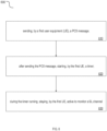
- the method 600 may include a portion or all of the following steps: step 610, sending, by a first user equipment (UE), a PC5 message; step 620, after sending the PC5 message, starting, by the first UE, a timer; and step 630, during the timer running, staying, by the first UE, active to monitor a SL channel.
- step 610 sending, by a first user equipment (UE), a PC5 message
- step 620 after sending the PC5 message, starting, by the first UE, a timer
- step 630 during the timer running, staying, by the first UE, active to monitor a SL channel.
- a value of the timer is received from a network or is per-configured.
- a time duration after the first UE sends the PC5 message the second UE starts a timer.
- the time duration comprises a number of millisecond (ms) or a number of slots.
- the time duration is received from a network or is per-configured.
- the first UE in response to receiving a second PC5 message from the second UE, stops the timer.
- a UE may monitor PC5 message, for example, a direct communication request, with a configured SL DRX configuration, which, for example but not limited to, may be performed during step 530 in FIG. 5 .
- the SL DRX configuration is acquire from the network or pre-configuration.
- the SL DRX configuration includes one or more SL DRX configurations.
- the DRX configuration includes: a DRX cycle, a slot offset, and an on duration timer.
- one of the SL DRX configuration is used when monitoring the message during Layer-2 link establishment procedure, for example: direct communication request message, or direct communication accept message.
- one of the DRX configuration is used when monitoring the PC5-S message
- the PC5-S message includes protected PC5-S message and/or unprotected PC5-S message.
- one of the DRX configuration is used when monitoring the message from UE1 before the UE2 acquire the DRX configuration of UE1 via PC5 RRC message.
- a direct communication accept message may be sent to UE-1 by the UE2 that has successfully established security with UE-1, which, for example but not limited to, may be performed during step 542 or 544 in FIG. 5 .
- a security with UE-1 may be established as one of the following methods.
- the target UE i.e. UE-2, responds by establishing the security with UE-1.
- the UEs that are interested in using the announced V2X service type(s) over a PC5 unicast link with UE-1 responds by establishing the security with UE-1.
- the UE1 restarts or starts a timer T0, when the T0 is running, the UE1 shall be in active to monitor the SL channel.
- a value of T0 and/or t is received from the network.
- the value of T0 and/or t is preconfigured.
- target user information is included in the direct communication request message, and the UE1 receive a PC5 message from the Target User, it can stop the timer T0.
- a UE2 monitors direct communication request message based on a SL DRX configuration.
- the SL DRX configuration is acquire from the network or pre-configuration.
- the SL DRX configuration includes one or more SL DRX configurations.
- the DRX configuration includes: a DRX cycle, a slot offset, and an on duration timer.
- one of the SL DRX configuration is used when monitoring the message during Layer-2 link establishment procedure, for example: direct communication request message, or direct communication accept message.
- one of the DRX configuration is used when monitoring the PC5-S message
- the PC5-S message includes protected PC5-S message and/or unprotected PC5-S message.
- UE 2 when UE 2 transmits a PC5-S message after receiving a direct communication request message, it may start an inactivity timer.
- the first UE in response to the obtained DRX profile information of the second UE indicating that the second UE does not supporting the DRX or not knowing whether the second UE supports the DRX, and the first UE supporting the DRX: the first UE monitors a reception resource pool for sidelink groupcast or broadcast to receive a PC5 message.
- the second PC5 message comprises a PC5-S message or a PC5-RRc message.
- the first UE in response to sending the PC5 message, starts a timer; and during the timer running, the first UE is active and monitor a SL channel.
- a time duration after the first UE sends the PC5 message the second UE starts a timer.
- the time duration comprises a number of millisecond (ms) or a number of slots.
- the time duration is received from a network or is per-configured.
- the first UE in response to a direct communication request message comprising a target user information and the first UE receiving a second PC5 message from the second UE, the first UE stops the timer.
- the time duration is same as a value of a round trip timer (RTT) timer.
- RTT round trip timer
- the first UE in response to sending the PC5 message, starts a RTT timer; in response to the RTT timer expiring, the first UE starts a timer; and during the timer running, the first UE is active and monitor a SL channel.
- a method 700 for wireless communication includes configuring a sidelink discontinuous reception (DRX).
- the method 700 may include a portion or all of the following steps: step 710, sending, by a first user equipment (UE), a PC5 message; step 720, in response to sending the PC5 message, starting, by the first UE, a round trip time (RTT) timer; step 730, in response to the RTT timer expiring, starting, by the first UE, a timer; and step 740, during the timer running, staying, by the first UE, active to monitor a SL channel.
- RTT round trip time
- a value of the timer is received from a network or is per-configured.
- a time duration after the first UE sends the PC5 message the second UE starts a timer.
- the time duration comprises a number of millisecond (ms) or a number of slots.
- the time duration is received from a network or is per-configured.
- a method 800 for wireless communication includes configuring a sidelink discontinuous reception (DRX).
- the method 800 may include a portion or all of the following steps: step 810, before a first user equipment (UE) sends a discontinuous reception (DRX) configuration message to a second UE via a PC5-RRC message, or before the first UE receives a DRX configuration of the first UE and sends a DRX configuration complete message via a PC5-RRC message: the first UE monitors the PC5 message from the second UE based on the DRX configuration, wherein the DRX configuration is acquired from the network or is pre-configured.
- UE user equipment
- DRX discontinuous reception
- the PC5 message comprises at least one of the following: a direct communication request message; a direct communication accept message; a PC5-S message during a layer-2 link establishment procedure; or a PC5-S message used to establish a security connection.
- in some embodiments may include situations wherein only the UE1 is DRX capable, and the UE2 is not DRX capable.
- the UE1 does not know whether UE2 is DRX capable UE.
- the target UE may be a no DRX capable UE.
- the UE-1 sends a PC5 message (such as Direct Communication Request message).
- a PC5 message such as Direct Communication Request message
- the UE-1 monitors the reception resource pool for sidelink groupcast or broadcast to receive the PC5 message, for example, PC5-S message or PC5-RRC message.
- the UE1 restarts or starts a timer T0, when the T0 is running, the UE1 may be in active to monitor the SL channel.
- t slots or t ms after sending a PC5 message (such as direct communication request), the UE2 restarts or starts a timer T0.
- the value of T0 and/or t is received from the network.
- the value of T0 and/or t is preconfigured.
- the target user information is included in the direct communication request message, and the UE1 receive a PC5 message from the target user, it may stop the timer T0.
- the t may be the same with a value of round trip timer (RTT) timer.
- RTT round trip timer
- the UE2 after sending a PC5 message (such as direct communication request), the UE2 restarts or starts a RTT timer. In another implementation, when the RTT timer is expired, it restarts or starts a timer T0. In another implementation, when the T0 is running, the UE1 may be in active to monitor the SL channel.
- a PC5 message such as direct communication request
- the first UE in response to the obtained DRX configuration information of the second UE indicating that the second UE supports the DRX and the first UE not supporting the DRX: the first UE sends the PC5 message to the second UE at any time.
- the second UE in response to the second UE not receiving any PC5 message during active time of the second UE for a long time, the second UE determines to monitor the PC5 message in no-active time.
- the second UE in response to the second UE receiving the PC5 message, the second UE sends a second PC5 message as a response to the received PC5 message.
- only UE2 is DRX capable, and UE1 may not be DRX capable.
- UE1 if UE1 is not DRX capable, it may send PC5 message at any time. If UE2 is configured with SL DRX, it may miss the PC5 message. For this issue, the UE 2 may decide whether to monitor the PC5 message in the no-active time if it cannot monitor any PC5 message during the active time for a long time.
- the UE2 may send another PC5 message as a response.
- the method then may include a portion or all of steps in one or more embodiments described above, including but not limited to switching the notations of UE1 and UE2.
- a method 900 for wireless communication includes configuring, by a first user equipment (UE), a discontinuous reception (DRX).
- the method 900 may include a portion or all of the following steps: step 910, sending, by the first UE, discontinuous reception (DRX) configuration assistance information to a second UE; and step 920, receiving, by the first UE, a DRX configuration sent from the second UE.
- step 910 sending, by the first UE, discontinuous reception (DRX) configuration assistance information to a second UE
- step 920 receiving, by the first UE, a DRX configuration sent from the second UE.
- the DRX configuration assistance information comprises a DRX configuration request.
- the DRX configuration assistance information comprises at least one of the following: at least one suggested value of an inactivity timer; or at least one allowed value of the inactivity timer.
- the inactivity time associates with a quality of service (QoS) profile.
- QoS quality of service
- the DRX configuration assistance information comprises at least one of the following: at least one suggested value of an on-duration timer; or at least one allowed value of the on-duration timer.
- the inactivity time associates with at least one of the following: a quality of service (QoS) profile; or a DRX cycle.
- QoS quality of service
- the second UE determines the DRX configuration according to a traffic pattern and a current DRX configuration of the first UE.
- the second UE determines the DRX configuration for a sidelink between the first UE and the second UE.
- the first UE before sending the DRX configuration assistance information, determines a default DRX configuration as the DRX configuration, wherein: in response to the first UE being in coverage, the first UE receives a mapping between a QoS requirement and a set of DRX configuration parameters from a network; in response to the first UE being out of coverage, the first UE pre-configures the mapping between the QoS requirement and the set of DRX configuration parameters; and the first UE determines the default DRX configuration based on the QoS requirement.
- the first UE determines at least one of the following: a cycle, an on-duration timer, an inactivity timer.
- the DRX configuration assistance information comprises at least one of a start offset or a slot offset to the second UE.
- the second UE selects the start offset or slot offset according to the DRX configuration assistance information.
- the second UE determines at least one of the following: a slot offset, or a RTT retransmission timer.
- a first UE in a first step, sends SL DRX configuration Assistant information to a second UE.
- the SL DRX configuration Assistant information includes SL DRX configuration request.
- the RX UE may send suggested SL DRX configurations to the second UE.
- the assistant information includes one of: suggested one or multiple values of inactivity timer, and/or allowed or accepted one or multiple maximum values of inactivity timer.
- each value of inactivity timer may associated a quality of service (QoS) profile.
- QoS quality of service
- the assistant information includes one of: suggested one or multiple values of on-duration timer, and/or allowed or accepted one or multiple maximum values of on-duration timer.
- each value of on-duration timer may associated a QoS profile.
- each value of on-duration timer may associated a DRX cycle.
- the second UE sends the SL DRX configuration to the first UE.
- the second UE decides the SL DRX configuration according to its traffic pattern and current SL DRX configuration of the first UE. For example, the second UE determines the SL DRX configurations of the first UE for the link between the first UE and the second UE.
- a first UE before the first step, considers a default DRX configuration as its SL DRX configuration, which may be implemented in more than one specific situations.
- the UE may receive a mapping between a quality of service requirement and a set of discontinuous reception configuration parameters or an index of the set of discontinuous reception configuration parameters from the network.
- the UE may preconfigure a mapping between a quality of service requirement and a set of discontinuous reception configuration parameters or an index of the set of discontinuous reception configuration parameters.
- the first UE decides the default DRX configuration based on the a quality of service requirement.
- a network may pre-configure a mapping between a QoS and at least one of a DRX cycle, an on-duration timer.
- a network may pre-configure a mapping between a QoS and whether a DRX is enabled.
- it may be uniformly configured for at least one of an on duration timer, an inactivity timer, or a RTT retransmission timer.
- a unicast mode it may be configured for a mapping between a level for a power saving need and at least one of an on-duration timer or an inactivity timer.
- a RX UE may determine at least one of the following parameters: a DRX cycle, an on-duration timer, an inactivity timer, or a suggested start offset.
- the RX UE may send the determined one or more parameters to a TX UE.
- the TX UE upon receiving the determined parameters, may only determine how to update an slot offset or an RTT retransmission timer.
- a method 1000 for wireless communication includes configuring a discontinuous reception (DRX).
- the method 1000 includes all of the following steps: step 1010, receiving, by a first user equipment (UE), a DRX configuration sent from a second UE; step 1020, in response to the first UE accepting the received DRX configuration, sending, by the first UE, indication information indicating that the received DRX configuration is accepted; and step 1030, in response to the first UE not accepting the received DRX configuration, sending, by the first UE, rejection information indicating that the received DRX configuration is rejected.
- UE user equipment
- step 1020 in response to the first UE accepting the received DRX configuration, sending, by the first UE, indication information indicating that the received DRX configuration is accepted
- step 1030 in response to the first UE not accepting the received DRX configuration, sending, by the first UE, rejection information indicating that the received DRX configuration is rejected.
- the first UE in response to the first UE not accepting the received DRX configuration, the first UE sends a suggested DRX pattern and the rejection information indicating the received DRX configuration is rejected.
- the rejection information comprises a cause value indicating at least one of the following: that the DRX configuration is not accepted; that an inactivity timer is not accepted; that an on-duration timer is not accepted; or that a slot offset or a start offset is not accepted.
- the first UE continues using the DRX configuration that is used prior to a reception of a PC5-RRC message.
- the first UE uses the DRX configuration received from a network.
- the DRX configuration comprises a default DRX configuration or a common DRX configuration.
- a second UE in a first step, sends the SL DRX configuration to a first UE via a PC5 RRC message.
- the first UE may perform various actions, including the following situations.
- the first UE may send indication information to indicate that the received SL DRX configuration is confirmed.
- the first UE may send the information to reject the DRX configuration of the second UE.
- the first UE may also send suggested DRX pattern to the second UE together with the reject information.
- the reject information may include a cause value.
- the cause value can indicate that the DRX configuration is not accepted; the cause value can indicate that the inactivity timer is not accepted; the cause value can indicate that the on duration timer is not accepted; or the cause value can indicate that the slot offset or start offset is not accepted.
- the first UE may continue using the SL DRX configuration used prior to the reception of the PC5 RRC message.
- the first UE may use the SL DRX configuration received from the network, for example, a default DRX configuration or a common DRX configuration.
- Methods in various embodiments may further include determining, by the first UE, whether a condition is satisfied; and in response to determining that the condition is satisfied, sending assistant information to the second UE as a reference, wherein the condition comprises at least one of the following: that a power saving requirement is changes; or that a current DRX configuration changes.
- the second UE in response to determining that a QoS traffic changes or a transmission resource changes, the second UE sends the updated DRX configuration to the first UE.
- the first UE in response to sending the DRX configuration assistance information, starts or restarts a first timer; and when the first timer is running, the first UE is not allowed to send a discontinuous reception (DRX) configuration assistance information to the second UE.
- DRX discontinuous reception
- the second UE in response to sending the DRX configuration information, starts or restarts a second timer; and when the second timer is running, the second UE is not allowed to send a DRX configuration information to the first UE.
- the value of the first or the second timer is received from the network or a peer UE.
- the value of the first or the second timer is pre-configured or specified.
- a UE may update a DRX configuration.
- the first UE may send an updated DRX configuration as DRX assistant information to other TX UE as reference.
- the first UE may send an updated DRX configuration as DRX assistant information to other TX UE as reference.
- the second UE may send an updated DRX configuration to the first UE.
- the second UE may send an updated DRX configuration to the first UE.
- a first UE may be a relay UE and a second UE may be a remote UE.
- the remote UE informs a relay UE on requested SIB type(s) via a PC5 RRC message. Then, the relay UE triggers legacy on-demand SI acquisition procedure according to its own RRC state, if needed, and sends the acquired SIB to the remote UE.
- an RRC_Connected relay UE can use a DedicatedSIBRequest procedure to request the SI.
- a DedicatedSIBRequest procedure to request the SI.
- PosSIB and SIB12, 13, 14 may be requested in a DedicatedSIBRequest.
- the RRC_Connected relay UE may have no way to acquire it. This may not an issue in current specification since those SIBs are not needed for a RRC_Connected UE.
- the relay UE may need to acquire those SIBs for the remote UE.
- an additional DedicatedSIBRequest message for example, which may be named as DedicatedSIBRequest -r17, may be introduced for a relay UE.
- DedicatedSIBRequest -r17 an additional DedicatedSIBRequest message, for example, which may be named as DedicatedSIBRequest -r17, may be introduced for a relay UE.
- more SIB(s) such as SIB2, 3, 4, ..., 11 may be requested.
- the UE may be allowed to request SIB(s) on-demand while in RRC_CONNECTED.
- the UE may set the contents of DedicatedSIBRequest message as follows: if the procedure is triggered to request the required SIB(s): include requestedSIB-List in the onDemandSIB-RequestList to indicate the requested SIB(s); and/or if the procedure is triggered to request the required posSIB(s): include requestedPosSIB-List in the onDemandSIB-RequestList to indicate the requested posSIB(s).
- the UE may submit the DedicatedSIBRequest message to lower layers for transmission.
- the requestedSIB-List in the onDemandSIB-RequestList may include only posSIB, SIB 12, SIB13, and SIB14.
- the requestedSIB-List in the onDemandSIB-RequestList may include at least one of SIB2, 3, 4, ..., 11.
- a UE may receive indications about Si modifications and/or public warning system (PWS) notifications using a short message transmitted with p-radio network temporary identifier (P-RNTI) over downlink control information(DCI).
- PWS public warning system
- DCI downlink control information
- the remote UE needs to be notified through PC5 signaling, such as a PC5 medium access control (MAC) control element (CE), a PC5 RRC message, or sidelink control information (SCI).
- PC5 signaling such as a PC5 medium access control (MAC) control element (CE), a PC5 RRC message, or sidelink control information (SCI).
- MAC medium access control
- CE PC5 RRC message
- SCI sidelink control information
- the relay UE in response to that a relay UE receives indications about SI modifications and/or PWS notifications using a short message transmitted with P-RNTI over DCI, the relay UE sends the indications about SI modifications and/or PWS notifications via a PC5 signaling.
- the PC5 signaling may be one of: a PC5 MAC CE, a PC5 RRC message, or SCI.
- the remote UE in response that the remote UE receives the indications about SI modifications and/or PWS notifications via a PC5 signaling, it informs a relay UE on requested SIB type(s) via a PC5 RRC message. Furthermore, the relay UE may send the updated SIB to the remote UE.
- the relay UE in response that a relay UE receives indications about SI modifications and/or PWS notifications using a short message transmitted with P-RNTI over DCI, the relay UE applies the SI acquisition procedure, and sends the updated SIB to the remote UE.
- the relay UE in response that the relay UE receives the requested SIB type(s) list via a PC5 RRC message from a remote UE before, the relay UE sends the updated SIB that belongs to the requested SIB type(s) list to the remote UE.
- a relay UE before a relay UE sends the indications about SI modifications and/or PWS notifications via a PC5 signaling, it receives an indication from a remote UE.
- the indication may indicate at least one of the following: a coverage state of the remote UE, for example, in coverage or out of coverage; request SIB forwarding that indicates the remote UE requesting the relay UE forwarding the SIB; request SI modifications and/or PWS notifications forwarding that indicates the remote UE requesting the relay UE forwarding the SI modifications and/or PWS notifications; or request SIB forwarding list that indicates which SIB(s) are requested to be forwarded.
- a relay UE before a relay UE sends the SIB via a PC5 RRC message to a remote UE, it receives an indication from a remote UE.
- the indication may indicate at least one of the following: a coverage state of the remote UE, for example, in coverage or out of coverage; request SIB forwarding that indicates the remote UE requesting the relay UE forwarding the SIB; request SI modifications and/or PWS notifications forwarding that indicates the remote UE requesting the relay UE forwarding the SI modifications and/or PWS notifications; or request SIB forwarding list that indicates which SIB(s) are requested to be forwarded.
- the present disclosure describes methods, apparatus, and computer-readable medium for wireless communication.
- the present disclosure addressed the issues with configuring a sidelink discontinuous reception (DRX).
- the methods, devices, and computer-readable medium described in the present disclosure may facilitate the performance of wireless communication by configuring a sidelink DRX, thus reducing power consumption, and improving efficiency and overall performance.
- the methods, devices, and computer-readable medium described in the present disclosure may improves the overall efficiency of the wireless communication systems.
Landscapes
- Engineering & Computer Science (AREA)
- Computer Networks & Wireless Communication (AREA)
- Signal Processing (AREA)
- Quality & Reliability (AREA)
- Databases & Information Systems (AREA)
- Mobile Radio Communication Systems (AREA)
- User Interface Of Digital Computer (AREA)
- Telephonic Communication Services (AREA)
- Information Transfer Between Computers (AREA)
Claims (15)
- Verfahren zur drahtlosen Kommunikation, aufweisend:Konfigurieren, durch ein erstes Benutzergerät, UE, eines diskontinuierlichen Empfangs, DRX, durchSenden, über das erste Benutzergerät, von Hilfsinformationen zur Konfiguration des diskontinuierlichen Empfangs, DRX, an ein zweites Benutzergerät;Empfangen, vom ersten Benutzergerät, einer vom zweiten Benutzergerät gesendeten DRX-Konfiguration;dadurch gekennzeichnet, dassin Antwort darauf, dass das erste Benutzergerät die empfangene DRX-Konfiguration annimmt, Senden durch das erste Benutzergerät von Angabeinformationen, die angeben,dass die empfangene DRX-Konfiguration akzeptiert wird; undin Antwort darauf, dass das erste Benutzergerät die empfangene DRX-Konfiguration nicht annimmt, Senden durch das erste Benutzergerät von Ablehnungsinformationen, die angeben, dass die empfangene DRX-Konfiguration abgelehnt wird.
- Verfahren nach Anspruch 1, wobei:
die Hilfsinformationen zur DRX-Konfiguration wenigstens einen der Folgenden aufweisen:wenigstens einen vorgeschlagenen Wert eines Inaktivitäts-Timers; oderwenigstens einen zulässigen Wert des Inaktivitäts-Timers. - Verfahren nach Anspruch 1, wobei:
die Hilfsinformationen zur DRX-Konfiguration wenigstens einen der Folgenden aufweisen:wenigstens einen vorgeschlagenen Wert eines Dauer-Timers; oderwenigstens einen zulässigen Wert des Dauer-Timers. - Verfahren nach Anspruch 1, wobei:vor dem Senden der Hilfsinformationen zur DRX-Konfiguration das erste Benutzergerät eine DRX-Standardkonfiguration als die DRX-Konfiguration bestimmt, wobeiin Antwort darauf, dass sich das erste Benutzergerät in der Abdeckung befindet, das erste Benutzergerät eine Zuordnung zwischen einer QoS-Anforderung und einer Gruppe von DRX-Konfigurationsparametern aus einem Netzwerk empfängt;in Antwort darauf, dass sich das erste Benutzergerät außerhalb der Abdeckung befindet, das erste Benutzergerät die Zuordnung zwischen der QoS-Anforderung und der Gruppe von DRX-Konfigurationsparametern vorkonfiguriert; unddas erste Benutzergerät die DRX-Standardkonfiguration basierend auf der QoS-Anforderung bestimmt.
- Verfahren nach Anspruch 1, wobei:
das zweite Benutzergerät wenigstens einen der Folgenden bestimmt:
einen Schlitz-Versatz oder einen RTT-Timer für die erneute Übertragung. - Verfahren nach Anspruch 1, zusätzlich aufweisend:Bestimmen durch das erste Benutzergerät, ob eine Bedingung erfüllt ist; undin Antwort auf das Bestimmen, dass die Bedingung erfüllt ist, Senden von Hilfsinformationen an das zweite Benutzergerät als eine Referenz, wobei die Bedingung wenigstens eines der Folgenden aufweist:dass sich eine Stromsparanforderung ändert; oderdass sich eine aktuelle DRX-Konfiguration ändert.
- Verfahren nach Anspruch 1, wobei:
in Antwort auf das Bestimmen, dass sich ein QoS-Verkehr ändert oder sich eine Übertragungsressource ändert, das zweite Benutzergerät eine aktualisierte DRX-Konfiguration an das erste Benutzergerät sendet. - Verfahren nach Anspruch 1, aufweisend:Senden durch das erste Benutzergerät einer PC5-Nachricht;in Antwort auf das Senden der PC5-Nachricht, Starten durch das erste Benutzergerät eines Roundtrip-Zeit-, RTT,-Timers;in Antwort darauf, dass der RTT-Timer abläuft, Starten durch das erste Benutzergerät eines Timers; undwährend der Timer läuft, bleibt das erste Benutzergerät aktiv, um einen SL-Kanal zu überwachen.
- Verfahren nach Anspruch 8, wobei:
ein Wert des Timers aus einem Netzwerk empfangen wird oder vorkonfiguriert wird. - Verfahren nach Anspruch 1, wobei:
das erste Benutzergerät die Verwendung der DRX-Konfiguration fortsetzt, die vor einem Empfang einer PC5-RRC-Nachricht verwendet wird. - Verfahren nach Anspruch 1, wobei:das erste Benutzergerät die DRX-Konfiguration verwendet, die aus einem Netzwerk empfangen wurde; und/oderdie DRX-Konfiguration eine DRX-Standardkonfiguration oder eine allgemeine DRX-Konfiguration aufweist.
- Verfahren nach Anspruch 1, aufweisend:Senden durch das erste Benutzergerät einer PC5-Nachricht;nach dem Senden der PC5-Nachricht, Starten durch das erste Benutzergerät eines Timers; undwährend der Timer ausgeführt wird, bleibt das erste Benutzergerät aktiv, um einen Sidelink-, SL,-Kanal zu überwachen,wobei ein Wert des Timers aus einem Netzwerk empfangen wird oder vorkonfiguriert ist.
- Verfahren nach Anspruch 12, wobei:
eine Zeitdauer, nach der das erste Benutzergerät die PCS-Nachricht sendet, das zweite Benutzergerät einen Timer startet. - Vorrichtung, aufweisend:einen Speicher, der Anweisungen speichert; undeinen Prozessor in Kommunikation mit dem Speicher, wobei, wenn der Prozessor die Anweisungen ausführt, der Prozessor dazu eingerichtet ist, die Vorrichtung zu veranlassen, ein Verfahren nach einem der Ansprüche 1 bis 13 auszuführen.
- Computerprogrammprodukt, das ein von einem Computer lesbares Programmmedium aufweist, das Anweisungen speichert, wobei die Anweisungen, wenn sie von einem Prozessor ausgeführt werden, ausgestaltet sind, den Prozessor zu veranlassen, ein Verfahren nach einem der Ansprüche 1 bis 13 auszuführen.
Priority Applications (1)
| Application Number | Priority Date | Filing Date | Title |
|---|---|---|---|
| EP24170813.0A EP4383930A3 (de) | 2021-05-08 | 2021-05-08 | Verfahren, vorrichtungen und systeme zur konfiguration von sidelink-drx |
Applications Claiming Priority (1)
| Application Number | Priority Date | Filing Date | Title |
|---|---|---|---|
| PCT/CN2021/092351 WO2022236466A1 (en) | 2021-05-08 | 2021-05-08 | Methods, devices, and systems for configuring sidelink drx |
Related Child Applications (2)
| Application Number | Title | Priority Date | Filing Date |
|---|---|---|---|
| EP24170813.0A Division EP4383930A3 (de) | 2021-05-08 | 2021-05-08 | Verfahren, vorrichtungen und systeme zur konfiguration von sidelink-drx |
| EP24170813.0A Division-Into EP4383930A3 (de) | 2021-05-08 | 2021-05-08 | Verfahren, vorrichtungen und systeme zur konfiguration von sidelink-drx |
Publications (3)
| Publication Number | Publication Date |
|---|---|
| EP4186329A1 EP4186329A1 (de) | 2023-05-31 |
| EP4186329A4 EP4186329A4 (de) | 2023-09-27 |
| EP4186329B1 true EP4186329B1 (de) | 2025-01-29 |
Family
ID=84027901
Family Applications (2)
| Application Number | Title | Priority Date | Filing Date |
|---|---|---|---|
| EP24170813.0A Pending EP4383930A3 (de) | 2021-05-08 | 2021-05-08 | Verfahren, vorrichtungen und systeme zur konfiguration von sidelink-drx |
| EP21941047.9A Active EP4186329B1 (de) | 2021-05-08 | 2021-05-08 | Verfahren, vorrichtung und computerprogramm produkt zur konfiguration von sidelink-drx |
Family Applications Before (1)
| Application Number | Title | Priority Date | Filing Date |
|---|---|---|---|
| EP24170813.0A Pending EP4383930A3 (de) | 2021-05-08 | 2021-05-08 | Verfahren, vorrichtungen und systeme zur konfiguration von sidelink-drx |
Country Status (7)
| Country | Link |
|---|---|
| US (1) | US20230199908A1 (de) |
| EP (2) | EP4383930A3 (de) |
| KR (1) | KR20230053606A (de) |
| CN (1) | CN117204113B (de) |
| CA (1) | CA3188360A1 (de) |
| ES (1) | ES3017762T3 (de) |
| WO (1) | WO2022236466A1 (de) |
Families Citing this family (5)
| Publication number | Priority date | Publication date | Assignee | Title |
|---|---|---|---|---|
| US12219649B2 (en) * | 2021-05-21 | 2025-02-04 | Lg Electronics Inc. | Method of operating a UE related to sidelink DRX in a wireless communication system |
| WO2023014129A1 (ko) * | 2021-08-05 | 2023-02-09 | 엘지전자 주식회사 | Nr v2x에서 sl drx 동작을 수행하는 방법 및 장치 |
| WO2024239214A1 (zh) * | 2023-05-22 | 2024-11-28 | 北京小米移动软件有限公司 | 非连续接收drx配置方法和装置 |
| KR20250043999A (ko) * | 2023-09-22 | 2025-03-31 | 삼성전자주식회사 | 무선 통신 시스템에서 디바이스들의 그룹 통신을 위한 방법 및 장치 |
| WO2025071441A1 (en) * | 2023-09-25 | 2025-04-03 | Telefonaktiebolaget Lm Ericsson (Publ) | Methods and apparatuses for providing assistance in alleviating in-device co-existence interference |
Family Cites Families (10)
| Publication number | Priority date | Publication date | Assignee | Title |
|---|---|---|---|---|
| CN108307489A (zh) * | 2016-08-11 | 2018-07-20 | 中兴通讯股份有限公司 | 信息处理方法、装置、用户设备及基站 |
| JP6917502B2 (ja) * | 2019-06-25 | 2021-08-11 | 華碩電腦股▲ふん▼有限公司 | 無線通信システムにおけるサイドリンク通信を構成するための方法および装置 |
| CN111800764B (zh) * | 2019-08-22 | 2022-05-13 | 维沃移动通信有限公司 | 边链路drx参数配置方法、装置及终端设备 |
| WO2021163527A1 (en) * | 2020-02-12 | 2021-08-19 | Idac Holdings, Inc. | Methods for performing discontinuous reception on sidelink |
| US12588101B2 (en) * | 2020-04-07 | 2026-03-24 | Kt Corporation | Method for controlling sidelink communication and device therefor |
| CN111556590B (zh) * | 2020-04-13 | 2022-07-19 | 中国信息通信研究院 | 一种边链路非连续接收方法 |
| EP4151042A4 (de) * | 2020-05-21 | 2024-07-17 | FG Innovation Company Limited | Verfahren und benutzervorrichtung zur durchführung von sidelink-kommunikation |
| WO2022119715A1 (en) * | 2020-12-04 | 2022-06-09 | Kyocera Corporation | Pc5 groupcast messages with selected system information |
| WO2022126345A1 (zh) * | 2020-12-14 | 2022-06-23 | 北京小米移动软件有限公司 | Drx配置方法及装置、通信设备和存储介质 |
| JP7634727B2 (ja) * | 2021-05-06 | 2025-02-21 | エルジー エレクトロニクス インコーポレイティド | Nr v2xにおけるdciに基づいてsl drxタイマーを開始する方法及び装置 |
-
2021
- 2021-05-08 KR KR1020237005796A patent/KR20230053606A/ko not_active Ceased
- 2021-05-08 EP EP24170813.0A patent/EP4383930A3/de active Pending
- 2021-05-08 WO PCT/CN2021/092351 patent/WO2022236466A1/en not_active Ceased
- 2021-05-08 CN CN202180097416.8A patent/CN117204113B/zh active Active
- 2021-05-08 EP EP21941047.9A patent/EP4186329B1/de active Active
- 2021-05-08 ES ES21941047T patent/ES3017762T3/es active Active
- 2021-05-08 CA CA3188360A patent/CA3188360A1/en active Pending
-
2023
- 2023-02-22 US US18/112,581 patent/US20230199908A1/en active Pending
Also Published As
| Publication number | Publication date |
|---|---|
| CN117204113A (zh) | 2023-12-08 |
| EP4383930A2 (de) | 2024-06-12 |
| WO2022236466A1 (en) | 2022-11-17 |
| CN117204113B (zh) | 2026-03-20 |
| ES3017762T3 (en) | 2025-05-13 |
| US20230199908A1 (en) | 2023-06-22 |
| EP4186329A1 (de) | 2023-05-31 |
| EP4186329A4 (de) | 2023-09-27 |
| EP4383930A3 (de) | 2024-09-04 |
| KR20230053606A (ko) | 2023-04-21 |
| CA3188360A1 (en) | 2022-11-17 |
Similar Documents
| Publication | Publication Date | Title |
|---|---|---|
| EP4186329B1 (de) | Verfahren, vorrichtung und computerprogramm produkt zur konfiguration von sidelink-drx | |
| CN102783221A (zh) | 用于指示网络单元的功率节约模式的设备和方法 | |
| JP2013544481A (ja) | 機器間通信を支援する無線接続システムにおいてマルチキャストトラフィックを送受信するための方法及び装置 | |
| CN112166646A (zh) | 减少无线通信系统中的终端功耗的方法和设备 | |
| US20230337319A1 (en) | Methods, devices, and systems for configuring sidelink drx | |
| EP3741176A1 (de) | Sparen von strom für drahtlose vorrichtung | |
| WO2022073395A1 (zh) | 一种通信方法及设备 | |
| EP3466153A1 (de) | Betrieb einer endgerätevorrichtung in einem mobilkommunikationsnetzwerk | |
| CN116724586A (zh) | 用于执行侧边发送和接收的方法和设备 | |
| US20240323911A1 (en) | Wireless network paging | |
| US20250351193A1 (en) | Method, device, and system for radio resource configuration | |
| CN118891941A (zh) | 用于无线网络中的数据传输的方法、设备和系统 | |
| US12568468B2 (en) | Methods, devices, and systems for small data transmission | |
| US12588093B2 (en) | Small data transmission | |
| WO2024187445A1 (en) | Method, device, and system for establishing ue network connection | |
| WO2024113577A1 (en) | Method, device, and system for discontinuous data transmission and reception in wireless networks |
Legal Events
| Date | Code | Title | Description |
|---|---|---|---|
| STAA | Information on the status of an ep patent application or granted ep patent |
Free format text: STATUS: THE INTERNATIONAL PUBLICATION HAS BEEN MADE |
|
| PUAI | Public reference made under article 153(3) epc to a published international application that has entered the european phase |
Free format text: ORIGINAL CODE: 0009012 |
|
| STAA | Information on the status of an ep patent application or granted ep patent |
Free format text: STATUS: REQUEST FOR EXAMINATION WAS MADE |
|
| 17P | Request for examination filed |
Effective date: 20230224 |
|
| AK | Designated contracting states |
Kind code of ref document: A1 Designated state(s): AL AT BE BG CH CY CZ DE DK EE ES FI FR GB GR HR HU IE IS IT LI LT LU LV MC MK MT NL NO PL PT RO RS SE SI SK SM TR |
|
| A4 | Supplementary search report drawn up and despatched |
Effective date: 20230829 |
|
| RIC1 | Information provided on ipc code assigned before grant |
Ipc: H04W 76/23 20180101ALN20230823BHEP Ipc: H04W 76/28 20180101AFI20230823BHEP |
|
| DAV | Request for validation of the european patent (deleted) | ||
| DAX | Request for extension of the european patent (deleted) | ||
| GRAP | Despatch of communication of intention to grant a patent |
Free format text: ORIGINAL CODE: EPIDOSNIGR1 |
|
| STAA | Information on the status of an ep patent application or granted ep patent |
Free format text: STATUS: GRANT OF PATENT IS INTENDED |
|
| RIC1 | Information provided on ipc code assigned before grant |
Ipc: H04W 76/23 20180101ALN20240930BHEP Ipc: H04W 76/28 20180101AFI20240930BHEP |
|
| RIC1 | Information provided on ipc code assigned before grant |
Ipc: H04W 76/23 20180101ALN20241022BHEP Ipc: H04W 76/28 20180101AFI20241022BHEP |
|
| INTG | Intention to grant announced |
Effective date: 20241104 |
|
| GRAS | Grant fee paid |
Free format text: ORIGINAL CODE: EPIDOSNIGR3 |
|
| GRAA | (expected) grant |
Free format text: ORIGINAL CODE: 0009210 |
|
| STAA | Information on the status of an ep patent application or granted ep patent |
Free format text: STATUS: THE PATENT HAS BEEN GRANTED |
|
| AK | Designated contracting states |
Kind code of ref document: B1 Designated state(s): AL AT BE BG CH CY CZ DE DK EE ES FI FR GB GR HR HU IE IS IT LI LT LU LV MC MK MT NL NO PL PT RO RS SE SI SK SM TR |
|
| REG | Reference to a national code |
Ref country code: GB Ref legal event code: FG4D |
|
| REG | Reference to a national code |
Ref country code: CH Ref legal event code: EP |
|
| REG | Reference to a national code |
Ref country code: DE Ref legal event code: R096 Ref document number: 602021025720 Country of ref document: DE |
|
| REG | Reference to a national code |
Ref country code: IE Ref legal event code: FG4D |
|
| PGFP | Annual fee paid to national office [announced via postgrant information from national office to epo] |
Ref country code: FR Payment date: 20250310 Year of fee payment: 5 |
|
| PGFP | Annual fee paid to national office [announced via postgrant information from national office to epo] |
Ref country code: GB Payment date: 20250320 Year of fee payment: 5 |
|
| REG | Reference to a national code |
Ref country code: ES Ref legal event code: FG2A Ref document number: 3017762 Country of ref document: ES Kind code of ref document: T3 Effective date: 20250513 |
|
| REG | Reference to a national code |
Ref country code: NL Ref legal event code: MP Effective date: 20250129 |
|
| PG25 | Lapsed in a contracting state [announced via postgrant information from national office to epo] |
Ref country code: NL Free format text: LAPSE BECAUSE OF FAILURE TO SUBMIT A TRANSLATION OF THE DESCRIPTION OR TO PAY THE FEE WITHIN THE PRESCRIBED TIME-LIMIT Effective date: 20250129 |
|
| PG25 | Lapsed in a contracting state [announced via postgrant information from national office to epo] |
Ref country code: RS Free format text: LAPSE BECAUSE OF FAILURE TO SUBMIT A TRANSLATION OF THE DESCRIPTION OR TO PAY THE FEE WITHIN THE PRESCRIBED TIME-LIMIT Effective date: 20250429 |
|
| PG25 | Lapsed in a contracting state [announced via postgrant information from national office to epo] |
Ref country code: FI Free format text: LAPSE BECAUSE OF FAILURE TO SUBMIT A TRANSLATION OF THE DESCRIPTION OR TO PAY THE FEE WITHIN THE PRESCRIBED TIME-LIMIT Effective date: 20250129 |
|
| PG25 | Lapsed in a contracting state [announced via postgrant information from national office to epo] |
Ref country code: PL Free format text: LAPSE BECAUSE OF FAILURE TO SUBMIT A TRANSLATION OF THE DESCRIPTION OR TO PAY THE FEE WITHIN THE PRESCRIBED TIME-LIMIT Effective date: 20250129 |
|
| PGFP | Annual fee paid to national office [announced via postgrant information from national office to epo] |
Ref country code: DE Payment date: 20250311 Year of fee payment: 5 |
|
| PGFP | Annual fee paid to national office [announced via postgrant information from national office to epo] |
Ref country code: ES Payment date: 20250605 Year of fee payment: 5 |
|
| REG | Reference to a national code |
Ref country code: LT Ref legal event code: MG9D |
|
| PG25 | Lapsed in a contracting state [announced via postgrant information from national office to epo] |
Ref country code: IS Free format text: LAPSE BECAUSE OF FAILURE TO SUBMIT A TRANSLATION OF THE DESCRIPTION OR TO PAY THE FEE WITHIN THE PRESCRIBED TIME-LIMIT Effective date: 20250529 Ref country code: NO Free format text: LAPSE BECAUSE OF FAILURE TO SUBMIT A TRANSLATION OF THE DESCRIPTION OR TO PAY THE FEE WITHIN THE PRESCRIBED TIME-LIMIT Effective date: 20250429 |
|
| PGFP | Annual fee paid to national office [announced via postgrant information from national office to epo] |
Ref country code: IT Payment date: 20250422 Year of fee payment: 5 |
|
| REG | Reference to a national code |
Ref country code: AT Ref legal event code: MK05 Ref document number: 1764672 Country of ref document: AT Kind code of ref document: T Effective date: 20250129 |
|
| PG25 | Lapsed in a contracting state [announced via postgrant information from national office to epo] |
Ref country code: HR Free format text: LAPSE BECAUSE OF FAILURE TO SUBMIT A TRANSLATION OF THE DESCRIPTION OR TO PAY THE FEE WITHIN THE PRESCRIBED TIME-LIMIT Effective date: 20250129 |
|
| PG25 | Lapsed in a contracting state [announced via postgrant information from national office to epo] |
Ref country code: PT Free format text: LAPSE BECAUSE OF FAILURE TO SUBMIT A TRANSLATION OF THE DESCRIPTION OR TO PAY THE FEE WITHIN THE PRESCRIBED TIME-LIMIT Effective date: 20250529 Ref country code: LV Free format text: LAPSE BECAUSE OF FAILURE TO SUBMIT A TRANSLATION OF THE DESCRIPTION OR TO PAY THE FEE WITHIN THE PRESCRIBED TIME-LIMIT Effective date: 20250129 |
|
| PG25 | Lapsed in a contracting state [announced via postgrant information from national office to epo] |
Ref country code: BG Free format text: LAPSE BECAUSE OF FAILURE TO SUBMIT A TRANSLATION OF THE DESCRIPTION OR TO PAY THE FEE WITHIN THE PRESCRIBED TIME-LIMIT Effective date: 20250129 Ref country code: GR Free format text: LAPSE BECAUSE OF FAILURE TO SUBMIT A TRANSLATION OF THE DESCRIPTION OR TO PAY THE FEE WITHIN THE PRESCRIBED TIME-LIMIT Effective date: 20250430 |
|
| PG25 | Lapsed in a contracting state [announced via postgrant information from national office to epo] |
Ref country code: AT Free format text: LAPSE BECAUSE OF FAILURE TO SUBMIT A TRANSLATION OF THE DESCRIPTION OR TO PAY THE FEE WITHIN THE PRESCRIBED TIME-LIMIT Effective date: 20250129 |
|
| PG25 | Lapsed in a contracting state [announced via postgrant information from national office to epo] |
Ref country code: SE Free format text: LAPSE BECAUSE OF FAILURE TO SUBMIT A TRANSLATION OF THE DESCRIPTION OR TO PAY THE FEE WITHIN THE PRESCRIBED TIME-LIMIT Effective date: 20250129 |
|
| PG25 | Lapsed in a contracting state [announced via postgrant information from national office to epo] |
Ref country code: SM Free format text: LAPSE BECAUSE OF FAILURE TO SUBMIT A TRANSLATION OF THE DESCRIPTION OR TO PAY THE FEE WITHIN THE PRESCRIBED TIME-LIMIT Effective date: 20250129 |
|
| PG25 | Lapsed in a contracting state [announced via postgrant information from national office to epo] |
Ref country code: DK Free format text: LAPSE BECAUSE OF FAILURE TO SUBMIT A TRANSLATION OF THE DESCRIPTION OR TO PAY THE FEE WITHIN THE PRESCRIBED TIME-LIMIT Effective date: 20250129 |
|
| PG25 | Lapsed in a contracting state [announced via postgrant information from national office to epo] |
Ref country code: CZ Free format text: LAPSE BECAUSE OF FAILURE TO SUBMIT A TRANSLATION OF THE DESCRIPTION OR TO PAY THE FEE WITHIN THE PRESCRIBED TIME-LIMIT Effective date: 20250129 Ref country code: EE Free format text: LAPSE BECAUSE OF FAILURE TO SUBMIT A TRANSLATION OF THE DESCRIPTION OR TO PAY THE FEE WITHIN THE PRESCRIBED TIME-LIMIT Effective date: 20250129 |
|
| PG25 | Lapsed in a contracting state [announced via postgrant information from national office to epo] |
Ref country code: RO Free format text: LAPSE BECAUSE OF FAILURE TO SUBMIT A TRANSLATION OF THE DESCRIPTION OR TO PAY THE FEE WITHIN THE PRESCRIBED TIME-LIMIT Effective date: 20250129 |
|
| PG25 | Lapsed in a contracting state [announced via postgrant information from national office to epo] |
Ref country code: SK Free format text: LAPSE BECAUSE OF FAILURE TO SUBMIT A TRANSLATION OF THE DESCRIPTION OR TO PAY THE FEE WITHIN THE PRESCRIBED TIME-LIMIT Effective date: 20250129 |
|
| REG | Reference to a national code |
Ref country code: DE Ref legal event code: R097 Ref document number: 602021025720 Country of ref document: DE |
|
| PLBE | No opposition filed within time limit |
Free format text: ORIGINAL CODE: 0009261 |
|
| STAA | Information on the status of an ep patent application or granted ep patent |
Free format text: STATUS: NO OPPOSITION FILED WITHIN TIME LIMIT |
|
| REG | Reference to a national code |
Ref country code: CH Ref legal event code: L10 Free format text: ST27 STATUS EVENT CODE: U-0-0-L10-L00 (AS PROVIDED BY THE NATIONAL OFFICE) Effective date: 20251210 |
|
| REG | Reference to a national code |
Ref country code: CH Ref legal event code: H13 Free format text: ST27 STATUS EVENT CODE: U-0-0-H10-H13 (AS PROVIDED BY THE NATIONAL OFFICE) Effective date: 20251223 |
|
| 26N | No opposition filed |
Effective date: 20251030 |
|
| PG25 | Lapsed in a contracting state [announced via postgrant information from national office to epo] |
Ref country code: LU Free format text: LAPSE BECAUSE OF NON-PAYMENT OF DUE FEES Effective date: 20250508 |
|
| PG25 | Lapsed in a contracting state [announced via postgrant information from national office to epo] |
Ref country code: CH Free format text: LAPSE BECAUSE OF NON-PAYMENT OF DUE FEES Effective date: 20250531 |
|
| REG | Reference to a national code |
Ref country code: BE Ref legal event code: MM Effective date: 20250531 |
|
| PG25 | Lapsed in a contracting state [announced via postgrant information from national office to epo] |
Ref country code: MC Free format text: LAPSE BECAUSE OF FAILURE TO SUBMIT A TRANSLATION OF THE DESCRIPTION OR TO PAY THE FEE WITHIN THE PRESCRIBED TIME-LIMIT Effective date: 20250129 |