EP4184804A1 - Algorithme pour atténuer l'impact d'une mauvaise correspondance de faisceau de liaison montante/liaison descendante - Google Patents
Algorithme pour atténuer l'impact d'une mauvaise correspondance de faisceau de liaison montante/liaison descendante Download PDFInfo
- Publication number
- EP4184804A1 EP4184804A1 EP22205050.2A EP22205050A EP4184804A1 EP 4184804 A1 EP4184804 A1 EP 4184804A1 EP 22205050 A EP22205050 A EP 22205050A EP 4184804 A1 EP4184804 A1 EP 4184804A1
- Authority
- EP
- European Patent Office
- Prior art keywords
- uplink
- priority
- beams
- access node
- beam set
- Prior art date
- Legal status (The legal status is an assumption and is not a legal conclusion. Google has not performed a legal analysis and makes no representation as to the accuracy of the status listed.)
- Pending
Links
- 238000004422 calculation algorithm Methods 0.000 title description 11
- 230000000116 mitigating effect Effects 0.000 title 1
- 230000009471 action Effects 0.000 claims abstract description 89
- 230000002787 reinforcement Effects 0.000 claims abstract description 63
- 230000005540 biological transmission Effects 0.000 claims abstract description 32
- 230000008859 change Effects 0.000 claims abstract description 22
- 238000010408 sweeping Methods 0.000 claims description 60
- 238000000034 method Methods 0.000 claims description 57
- 238000004590 computer program Methods 0.000 claims description 25
- 230000004044 response Effects 0.000 claims description 21
- 239000013598 vector Substances 0.000 claims description 11
- 230000000977 initiatory effect Effects 0.000 claims description 2
- 230000008569 process Effects 0.000 description 43
- 238000004891 communication Methods 0.000 description 42
- 230000006870 function Effects 0.000 description 26
- 238000013528 artificial neural network Methods 0.000 description 17
- 210000004027 cell Anatomy 0.000 description 17
- 238000004364 calculation method Methods 0.000 description 13
- 238000005516 engineering process Methods 0.000 description 10
- 238000003860 storage Methods 0.000 description 8
- 238000012549 training Methods 0.000 description 8
- 230000004913 activation Effects 0.000 description 6
- 238000005259 measurement Methods 0.000 description 5
- 238000005457 optimization Methods 0.000 description 4
- 238000012545 processing Methods 0.000 description 4
- 238000012935 Averaging Methods 0.000 description 3
- 238000013459 approach Methods 0.000 description 3
- 230000001186 cumulative effect Effects 0.000 description 3
- 238000013500 data storage Methods 0.000 description 3
- 238000013135 deep learning Methods 0.000 description 3
- 238000009826 distribution Methods 0.000 description 3
- 238000007476 Maximum Likelihood Methods 0.000 description 2
- 230000003190 augmentative effect Effects 0.000 description 2
- 238000013475 authorization Methods 0.000 description 2
- 230000008901 benefit Effects 0.000 description 2
- 230000015556 catabolic process Effects 0.000 description 2
- 230000001413 cellular effect Effects 0.000 description 2
- 238000006731 degradation reaction Methods 0.000 description 2
- 238000005315 distribution function Methods 0.000 description 2
- 238000011156 evaluation Methods 0.000 description 2
- 230000006872 improvement Effects 0.000 description 2
- 230000007774 longterm Effects 0.000 description 2
- 238000010295 mobile communication Methods 0.000 description 2
- 230000006855 networking Effects 0.000 description 2
- 230000003287 optical effect Effects 0.000 description 2
- 239000000523 sample Substances 0.000 description 2
- 239000004065 semiconductor Substances 0.000 description 2
- 238000001228 spectrum Methods 0.000 description 2
- 238000005303 weighing Methods 0.000 description 2
- 241001465754 Metazoa Species 0.000 description 1
- 230000002776 aggregation Effects 0.000 description 1
- 238000004220 aggregation Methods 0.000 description 1
- 238000004458 analytical method Methods 0.000 description 1
- 238000003491 array Methods 0.000 description 1
- 230000002567 autonomic effect Effects 0.000 description 1
- 230000006399 behavior Effects 0.000 description 1
- 230000009286 beneficial effect Effects 0.000 description 1
- 230000000295 complement effect Effects 0.000 description 1
- 230000001419 dependent effect Effects 0.000 description 1
- 230000000694 effects Effects 0.000 description 1
- 230000001747 exhibiting effect Effects 0.000 description 1
- 238000005562 fading Methods 0.000 description 1
- 230000014509 gene expression Effects 0.000 description 1
- 230000010354 integration Effects 0.000 description 1
- 230000003993 interaction Effects 0.000 description 1
- 238000010801 machine learning Methods 0.000 description 1
- 238000007726 management method Methods 0.000 description 1
- 238000013507 mapping Methods 0.000 description 1
- 238000003062 neural network model Methods 0.000 description 1
- 210000002569 neuron Anatomy 0.000 description 1
- 238000003909 pattern recognition Methods 0.000 description 1
- 238000010187 selection method Methods 0.000 description 1
- 230000011664 signaling Effects 0.000 description 1
- 238000004088 simulation Methods 0.000 description 1
- 238000001774 stimulated Raman spectroscopy Methods 0.000 description 1
- 238000012546 transfer Methods 0.000 description 1
- 230000001960 triggered effect Effects 0.000 description 1
Images


Classifications
-
- H—ELECTRICITY
- H04—ELECTRIC COMMUNICATION TECHNIQUE
- H04B—TRANSMISSION
- H04B7/00—Radio transmission systems, i.e. using radiation field
- H04B7/02—Diversity systems; Multi-antenna system, i.e. transmission or reception using multiple antennas
- H04B7/04—Diversity systems; Multi-antenna system, i.e. transmission or reception using multiple antennas using two or more spaced independent antennas
- H04B7/06—Diversity systems; Multi-antenna system, i.e. transmission or reception using multiple antennas using two or more spaced independent antennas at the transmitting station
- H04B7/0686—Hybrid systems, i.e. switching and simultaneous transmission
- H04B7/0695—Hybrid systems, i.e. switching and simultaneous transmission using beam selection
-
- H—ELECTRICITY
- H04—ELECTRIC COMMUNICATION TECHNIQUE
- H04W—WIRELESS COMMUNICATION NETWORKS
- H04W72/00—Local resource management
- H04W72/50—Allocation or scheduling criteria for wireless resources
- H04W72/54—Allocation or scheduling criteria for wireless resources based on quality criteria
- H04W72/542—Allocation or scheduling criteria for wireless resources based on quality criteria using measured or perceived quality
-
- H—ELECTRICITY
- H04—ELECTRIC COMMUNICATION TECHNIQUE
- H04B—TRANSMISSION
- H04B7/00—Radio transmission systems, i.e. using radiation field
- H04B7/02—Diversity systems; Multi-antenna system, i.e. transmission or reception using multiple antennas
- H04B7/04—Diversity systems; Multi-antenna system, i.e. transmission or reception using multiple antennas using two or more spaced independent antennas
- H04B7/08—Diversity systems; Multi-antenna system, i.e. transmission or reception using multiple antennas using two or more spaced independent antennas at the receiving station
- H04B7/0837—Diversity systems; Multi-antenna system, i.e. transmission or reception using multiple antennas using two or more spaced independent antennas at the receiving station using pre-detection combining
- H04B7/0842—Weighted combining
- H04B7/086—Weighted combining using weights depending on external parameters, e.g. direction of arrival [DOA], predetermined weights or beamforming
-
- G—PHYSICS
- G06—COMPUTING; CALCULATING OR COUNTING
- G06N—COMPUTING ARRANGEMENTS BASED ON SPECIFIC COMPUTATIONAL MODELS
- G06N3/00—Computing arrangements based on biological models
- G06N3/02—Neural networks
- G06N3/08—Learning methods
- G06N3/092—Reinforcement learning
-
- H—ELECTRICITY
- H04—ELECTRIC COMMUNICATION TECHNIQUE
- H04B—TRANSMISSION
- H04B7/00—Radio transmission systems, i.e. using radiation field
- H04B7/02—Diversity systems; Multi-antenna system, i.e. transmission or reception using multiple antennas
- H04B7/04—Diversity systems; Multi-antenna system, i.e. transmission or reception using multiple antennas using two or more spaced independent antennas
- H04B7/08—Diversity systems; Multi-antenna system, i.e. transmission or reception using multiple antennas using two or more spaced independent antennas at the receiving station
- H04B7/0868—Hybrid systems, i.e. switching and combining
- H04B7/088—Hybrid systems, i.e. switching and combining using beam selection
-
- H—ELECTRICITY
- H04—ELECTRIC COMMUNICATION TECHNIQUE
- H04W—WIRELESS COMMUNICATION NETWORKS
- H04W24/00—Supervisory, monitoring or testing arrangements
- H04W24/02—Arrangements for optimising operational condition
-
- H—ELECTRICITY
- H04—ELECTRIC COMMUNICATION TECHNIQUE
- H04W—WIRELESS COMMUNICATION NETWORKS
- H04W24/00—Supervisory, monitoring or testing arrangements
- H04W24/08—Testing, supervising or monitoring using real traffic
-
- H—ELECTRICITY
- H04—ELECTRIC COMMUNICATION TECHNIQUE
- H04W—WIRELESS COMMUNICATION NETWORKS
- H04W72/00—Local resource management
- H04W72/04—Wireless resource allocation
- H04W72/044—Wireless resource allocation based on the type of the allocated resource
- H04W72/0453—Resources in frequency domain, e.g. a carrier in FDMA
-
- H—ELECTRICITY
- H04—ELECTRIC COMMUNICATION TECHNIQUE
- H04W—WIRELESS COMMUNICATION NETWORKS
- H04W72/00—Local resource management
- H04W72/04—Wireless resource allocation
- H04W72/044—Wireless resource allocation based on the type of the allocated resource
- H04W72/046—Wireless resource allocation based on the type of the allocated resource the resource being in the space domain, e.g. beams
-
- G—PHYSICS
- G06—COMPUTING; CALCULATING OR COUNTING
- G06N—COMPUTING ARRANGEMENTS BASED ON SPECIFIC COMPUTATIONAL MODELS
- G06N3/00—Computing arrangements based on biological models
- G06N3/004—Artificial life, i.e. computing arrangements simulating life
- G06N3/006—Artificial life, i.e. computing arrangements simulating life based on simulated virtual individual or collective life forms, e.g. social simulations or particle swarm optimisation [PSO]
Definitions
- Various example embodiments relate to wireless communications.
- a 5G-NR access node determines the best downlink (DL) and uplink (UL) beams for a specific 5G-NR terminal device (or user equipment, UE) based on feedback received from the terminal device.
- a 5G-NR terminal device measures the beams formed by the access node and reports the best beams as a UL transmission.
- the received beam power is typically determined by averaging the received power from each access node transmit beam across all antennas of the terminal device. The beam with the highest received power is fed back to the access node as the best DL beam. That beam is also designated by default as the best UL beam (the beam used by the access node for receiving when the terminal device transmits in UL).
- UMTS universal mobile telecommunications system
- UTRAN radio access network
- LTE long term evolution
- WLAN wireless local area network
- WiFi worldwide interoperability for microwave access
- Bluetooth ® personal communications services
- PCS personal communications services
- WCDMA wideband code division multiple access
- UWB ultra-wideband
- IMS Internet Protocol multimedia subsystems
- Figure 1 depicts examples of simplified system architectures only showing some elements and functional entities, all being logical units, whose implementation may differ from what is shown.
- the connections shown in Figure 1 are logical connections; the actual physical connections may be different. It is apparent to a person skilled in the art that the system typically comprises also other functions and structures than those shown in Figure 1 .
- Figure 1 shows a part of an exemplifying radio access network.
- Figure 1 shows devices 100 and 102.
- the devices 100 and 102 may, for example, be user devices.
- the devices 100 and 102 are configured to be in a wireless connection on one or more communication channels with a node 104.
- the node 104 is further connected to a core network 110.
- the node 104 may be an access node such as (e/g)NodeB providing or serving devices in a cell.
- the node 104 may be a non-3GPP access node.
- the physical link from a device to a (e/g)NodeB is called uplink or reverse link and the physical link from the (e/g)NodeB to the device is called downlink or forward link.
- (e/g)NodeBs or their functionalities may be implemented by using any node, host, server or access point etc. entity suitable for such a usage.
- a communications system typically comprises more than one (e/g)NodeB in which case the (e/g)NodeBs may also be configured to communicate with one another over links, wired or wireless, designed for the purpose. These links may be used for signalling purposes.
- the (e/g)NodeB is a computing device configured to control the radio resources of communication system it is coupled to.
- the NodeB may also be referred to as a base station, an access point or any other type of interfacing device including a relay station capable of operating in a wireless environment.
- the (e/g)NodeB includes or is coupled to transceivers. From the transceivers of the (e/g)NodeB, a connection is provided to an antenna unit that establishes bi-directional radio links to devices.
- the antenna unit may comprise a plurality of antennas or antenna elements.
- the (e/g)NodeB is further connected to the core network 110 (CN or next generation core NGC).
- the counterpart on the CN side can be a serving gateway (S-GW, routing and forwarding user data packets), packet data network gateway (P-GW), for providing connectivity of devices (UEs) to external packet data networks, or mobile management entity (MME), etc.
- S-GW serving gateway
- P-GW packet data network gateway
- MME mobile management entity
- the device also called user device, UE, user equipment, user terminal, terminal device, etc.
- the device illustrates one type of an apparatus to which resources on the air interface are allocated and assigned, and thus any feature described herein with a device may be implemented with a corresponding apparatus, such as a relay node.
- a relay node is a layer 3 relay (self-backhauling relay) towards the base station.
- the device typically refers to a device (e.g. a portable or non-portable computing device) that includes wireless mobile communication devices operating with or without a subscriber identification module (SIM), including, but not limited to, the following types of devices: a mobile station (mobile phone), smartphone, personal digital assistant (PDA), handset, device using a wireless modem (alarm or measurement device, etc.), laptop and/or touch screen computer, tablet, game console, notebook, and multimedia device.
- SIM subscriber identification module
- a mobile station mobile phone
- smartphone personal digital assistant
- PDA personal digital assistant
- handset device using a wireless modem (alarm or measurement device, etc.)
- laptop and/or touch screen computer tablet, game console, notebook, and multimedia device.
- a device may also be a nearly exclusive uplink only device, of which an example is a camera or video camera loading images or video clips to a network.
- a device may also be a device having capability to operate in Internet of Things (IoT) network which is a scenario in which objects are provided with the ability to transfer data over a network without requiring human-to-human or human-to-computer interaction, e.g., to be used in smart power grids and connected vehicles.
- IoT Internet of Things
- the device may also utilise cloud.
- a device may comprise a user portable device with radio parts (such as a watch, earphones or eyeglasses) and the computation is carried out in the cloud.
- the device (or in some embodiments a layer 3 relay node) is configured to perform one or more of user equipment functionalities.
- the device may also be called a subscriber unit, mobile station, remote terminal, access terminal, user terminal or user equipment (UE) just to mention but a few names or apparatuses.
- CPS cyber-physical system
- ICT devices sensors, actuators, processors micro-controllers, etc.
- Mobile cyber physical systems in which the physical system in question has inherent mobility, are a subcategory of cyber-physical systems. Examples of mobile physical systems include mobile robotics and electronics transported by humans or animals.
- apparatuses have been depicted as single entities, different units, processors and/or memory units (not all shown in Figure 1 ) may be implemented.
- 5G enables using multiple input - multiple output (MIMO) antennas, many more base stations or nodes than the LTE (a so-called small cell concept), including macro sites operating in co-operation with smaller stations and employing a variety of radio technologies depending on service needs, use cases and/or spectrum available.
- MIMO multiple input - multiple output
- 5G mobile communications supports a wide range of use cases and related applications including video streaming, augmented reality, different ways of data sharing and various forms of machine type applications (such as (massive) machine-type communications (mMTC), including vehicular safety, different sensors and real-time control.
- 5G is expected to have multiple radio interfaces, namely below 6GHz, cmWave and mmWave, and also being integrable with existing legacy radio access technologies, such as the LTE.
- Integration with the LTE may be implemented, at least in the early phase, as a system, where macro coverage is provided by the LTE and 5G radio interface access comes from small cells by aggregation to the LTE.
- 5G is planned to support both inter-RAT operability (such as LTE-5G) and inter-RI operability (inter-radio interface operability, such as below 6GHz - cmWave, below 6GHz - cmWave - mmWave).
- inter-RAT operability such as LTE-5G
- inter-RI operability inter-radio interface operability, such as below 6GHz - cmWave, below 6GHz - cmWave - mmWave.
- One of the concepts considered to be used in 5G networks is network slicing in which multiple independent and dedicated virtual sub-networks (network instances) may be created within the same infrastructure to run services that have different requirements on latency, reliability, throughput and mobility.
- the current architecture in LTE networks is fully distributed in the radio and fully centralized in the core network.
- the low latency applications and services in 5G require to bring the content close to the radio which leads to local break out and multi-access edge computing (MEC).
- MEC multi-access edge computing
- 5G enables analytics and knowledge generation to occur at the source of the data. This approach requires leveraging resources that may not be continuously connected to a network such as laptops, smartphones, tablets and sensors.
- MEC provides a distributed computing environment for application and service hosting. It also has the ability to store and process content in close proximity to cellular subscribers for faster response time.
- Edge computing covers a wide range of technologies such as wireless sensor networks, mobile data acquisition, mobile signature analysis, cooperative distributed peer-to-peer ad hoc networking and processing also classifiable as local cloud/fog computing and grid/mesh computing, dew computing, mobile edge computing, cloudlet, distributed data storage and retrieval, autonomic self-healing networks, remote cloud services, augmented and virtual reality, data caching, Internet of Things (massive connectivity and/or latency critical), critical communications (autonomous vehicles, traffic safety, real-time analytics, time-critical control, healthcare applications).
- the communication system is also able to communicate with other networks, such as a public switched telephone network or the Internet 112, or utilize services provided by them.
- the communication network may also be able to support the usage of cloud services, for example at least part of core network operations may be carried out as a cloud service (this is depicted in Figure 1 by "cloud" 114).
- the communication system may also comprise a central control entity, or a like, providing facilities for networks of different operators to cooperate for example in spectrum sharing.
- Edge cloud may be brought into a radio access network (RAN) by utilizing network function virtualization (NVF) and software defined networking (SDN).
- RAN radio access network
- NVF network function virtualization
- SDN software defined networking
- Using the technology of edge cloud may mean access node operations to be carried out, at least partly, in a server, host or node operationally coupled to a remote radio head or base station comprising radio parts. It is also possible that node operations will be distributed among a plurality of servers, nodes or hosts.
- Application of cloudRAN architecture enables RAN real time functions being carried out at the RAN side (in a distributed unit, DU 104) and non-real time functions being carried out in a centralized manner (in a centralized unit, CU 108).
- 5G may also utilize satellite communication to enhance or complement the coverage of 5G service, for example by providing backhauling.
- Possible use cases are providing service continuity for machine-to-machine (M2M) or Internet of Things (loT) devices or for passengers on board of vehicles, or ensuring service availability for critical communications, and future railway/maritime/aeronautical communications.
- Satellite communication may utilise geostationary earth orbit (GEO) satellite systems, but also low earth orbit (LEO) satellite systems, in particular mega-constellations (systems in which hundreds of (nano)satellites are deployed).
- GEO geostationary earth orbit
- LEO low earth orbit
- mega-constellations systems in which hundreds of (nano)satellites are deployed.
- Each satellite 106 in the mega-constellation may cover several satellite-enabled network entities that create on-ground cells.
- the on-ground cells may be created through an on-ground relay node 104 or by a gNB located on-ground or in a satellite.
- the depicted system is only an example of a part of a radio access system and in practice, the system may comprise a plurality of (e/g)NodeBs, the device may have an access to a plurality of radio cells and the system may comprise also other apparatuses, such as physical layer relay nodes or other network elements, etc. At least one of the (e/g)NodeBs or may be a Home(e/g)nodeB. Additionally, in a geographical area of a radio communication system a plurality of different kinds of radio cells as well as a plurality of radio cells may be provided.
- Radio cells may be macro cells (or umbrella cells) which are large cells, usually having a diameter of up to tens of kilometers, or smaller cells such as micro-, femto- or picocells.
- the (e/g)NodeBs of Figure 1 may provide any kind of these cells.
- a cellular radio system may be implemented as a multilayer network including several kinds of cells. Typically, in multilayer networks, one access node provides one kind of a cell or cells, and thus a plurality of (e/g)NodeBs are required to provide such a network structure.
- a network which is able to use “plug-and-play" (e/g)Node Bs includes, in addition to Home (e/g)NodeBs (H(e/g)nodeBs), a home node B gateway, or HNB-GW (not shown in Figure 1 ).
- HNB-GW HNB Gateway
- a HNB Gateway (HNB-GW) which is typically installed within an operator's network may aggregate traffic from a large number of HNBs back to a core network.
- a 5G-NR access node determines the best downlink (DL) and uplink (UL) beams for a specific 5G-NR terminal device (or user equipment, UE) based on feedback received from the terminal device.
- a 5G-NR terminal device measures the beams formed by the access node and reports the best beams as a UL transmission.
- the received beam power is typically determined by averaging the received power from each access node transmit beam across all antennas of the terminal device. The beam with the highest received power is fed back to the access node as the best DL beam. That beam is also designated by default as the best UL beam (the beam used by the access node for receiving when the terminal device transmits in UL).
- TRP transmission/reception point
- the TRP i.e., the access node
- the TRP sweeps through all of the beams to determine the best beam for (UL) reception
- the problem may not arise.
- that may not be feasible due to resource constraints or due to the channel fading statistics.
- the best beam may change before the full sweep of the beams can be completed.
- the optimal DL beam determined by averaging the received power across all antennas of the terminal device is the same as the best UL beam.
- the terminal device using an UL beam corresponding to the optimal DL beam may experience inferior UL link quality due to this mismatch. In the field, this may even lead to call drops.
- the access node may need to sweep all possible beams for UL reception until it finds a good UL beam. This comes with additional overhead and delay. Due to multipath, the optimal UL beam could differ from the adjacent beams to the optimal DL beam. Therefore, more sophisticated algorithms are needed.
- Embodiments to be discussed seek to overcome the aforementioned problems by providing means for determining the one or more UL beams most likely to be optimal.
- the optimal UL beam may be found efficiently without having to go through all the possible beams.
- Said one or more most likely UL beams are called in the following a priority beam set while the zero or more UL beams (typically, a plurality of UL beams) of the access node not in the priority beam set are called in the following a secondary beam set.
- the priority and secondary beam sets are disjoint set (i.e., sets with no common elements).
- Figure 2 illustrates a process according to embodiments for defining and training a reinforcement training -based model for determining the most likely UL beams for a given DL beam.
- the process of Figure 3 may be carried out by an apparatus (e.g., a computing device).
- the apparatus may be, be comprised in or communicatively connected to an access node (e.g., an access node 104 of Figure 1 ).
- the apparatus may initially maintain, in block 201, in at least one memory, UL reference signal received power (RSRP) statistics for signals measured using a plurality of UL beams of the access node from a plurality of terminal devices and a plurality of optimal DL beams of the access node for transmission to said plurality of terminal devices.
- said at least one memory may comprise at least one (internal) memory of the apparatus and/or at least one external memory (i.e., a memory not forming an intrinsic part of the apparatus) such as a memory of an external storage device or a cloud-based memory or storage.
- Said plurality of optimal DL beams may be specifically beams which have been reported previously, respectively, by the plurality of terminal devices to the access node (and further to the apparatus) as being optimal for DL reception at a given terminal device.
- said at least one memory may comprise information for identifying, given a DL beam of the plurality of DL beams of the access node, a set of one or more terminal devices (later called source terminal device) for which said DL beam is optimal.
- the RSRP statistics stored in said at least one memory may have been determined by the apparatus or the access node (or other entity) based on a plurality of physical uplink control channel (PUCCH), physical uplink shared channel (PUSCH) and/or sounding reference signal (SRS) measurements at the access node.
- PUCCH physical uplink control channel
- PUSCH physical uplink shared channel
- SRS sounding reference signal
- the RSRP statistics and information on the plurality of optimal DL beams may be stored, for example, in a table T. There may be no need to save information regarding the identities of the plurality of terminal devices from which reports have been received in said table.
- a new entry to the table is added, by the apparatus, to the table in response to a new RSRP measurement becoming available.
- Over time beams serving many users may have multiple entries in the table.
- a single entry of the table may comprise, e.g., at least the RSRP information of the measured UL beam(s) and a beam index (or some other identifier) of the optimal DL beam.
- the beam index may have, for example, an integer value corresponding to a particular DL beam of the plurality of DL beams of the access node.
- the apparatus may initially maintain, in block 201, in said at least one memory, uplink signal-to-noise ratio statistics derived or derivable from said uplink reference signal received power statistics, instead of or in addition to maintaining, in said at least one memory, said uplink reference signal received power statistics.
- block 201 may be omitted (e.g., said information may, instead of being maintained in said at least one memory, be obtained or retrieved from another device or from an external memory when it is needed for calculations such as for calculations of block 203).
- the apparatus defines (or generates or establishes), in block 202, separately for at least one DL beam (or for each DL beam) of a plurality of DL beams of the access node, a reinforcement learning model.
- a reinforcement learning model is, in general, characterized by the states, actions and rewards defined for it.
- states, actions and rewards of a reinforcement learning model corresponding to a particular DL beam are defined as follows.
- a state of the reinforcement learning model defines which of the plurality of UL beams of the access node belong to a priority beam set for UL reception from one or more source terminal devices which reported said particular DL beam as the optimal DL beam.
- the state defines which of the plurality of UL beams are considered likely to correspond to the optimal UL beam for said one or more source terminal devices and which are not.
- the state for an nth DL beam of the plurality of DL beams of the access node may be defined, for example, as a binary vector b n having a length N corresponding to the number of the plurality of UL beams of the access node (or equally of the plurality of DL beams of the access node).
- An element b i n of the binary vector b n corresponds to an i th UL beam ( i having integer values, e.g., from 1 to N or equally from 0 to N -1) .
- Each element having a first value may correspond to the primary beam set while each element having a second value may correspond to the secondary beam set, where the first and second values are, respectively, 0 and 1 or 1 and 0.
- corresponding functionalities may be implemented equally using a real- or integer-valued vector, where each of the priority and secondary beam sets are indicated with certain pre-defined value(s).
- An action in a given state is defined as an addition of a new UL beam of the plurality of UL beams of the access node to the priority beam set, a removal of a UL beam from the priority beam set or doing nothing.
- the addition of a new UL beam to the priority beam set implies that an UL beam is moved from the secondary beam set to the priority beam set while the removal of a UL beam implies that the UL beam is moved from the priority beam set to the secondary beam set.
- the option of doing nothing is included here so as to be able to determine when an optimal solution is found (i.e., when doing nothing is the most beneficial action that can be taken).
- An action may be defined more formally, for example, in the following manner.
- an action for an i th UL beam of the plurality of UL beams of the access node may be defined as an integer a i n having a value satisfying ⁇ N ⁇ a i n ⁇ N .
- Following actions may be defined:
- the binary vector defining the priority beam set corresponding to an n th DL beam is transitioned from b n to b ' n .
- Binary vectors b n and b ' n may differ only up to one element (i.e., b ' n corresponds to b n with a value of zero or one element changed from 0 to 1 or from 1 to 0).
- a reward of taking an action in a given state is calculated based on a change in UL signal-to-noise ratio (SNR) statistics of one or more source terminal devices due to an action adjusted with a cost for taking that action.
- the one or more source terminal devices are terminal devices for which a DL beam associated with the particular reinforcement learning model is the optimal DL beam (as described also above).
- the cost may correspond to a positive, negative or zero cost depending on whether the action relates adding a UL beam to the priority beam set, removing a UL beam from the priority beams or doing nothing, respectively.
- the change in the UL SNR statistics (called the SNR metric in the following) is defined as a dB-difference between A th percentile signal-to-noise ratios after and before taking the action or as a sum or a weighted sum of a plurality of dB-differences between signal-to-noise ratios after and before taking the action calculated for different percentiles.
- A is, here, a positive real number smaller than or equal to 100.
- a reward may be defined more formally, for example, in the following (deterministic) manner.
- ⁇ SNR A % and ⁇ SNR A % may correspond to a difference associated with a change from a state b to a modified state b' (as defined above).
- Parameters A and B are positive real numbers smaller than or equal to 100. Parameters A and B have different values. A may have a value selected from a range 0-50 and/or B may have a value selected from a range 50-100. For example, A may have a value of 5 and/or B may have a value of 50.
- the cost parameter ⁇ add is defined to be zero or positive (i.e., adding a UL beam to the priority beam set is associated with a positive cost).
- ⁇ and/or ⁇ add may optionally be defined differently for different reinforcement learning models (i.e., for different n ).
- the marginal improvement due to adding a UL beam defined by the SNR metric ⁇ SNR A % n dB + ⁇ SNR B % n dB is always either positive or zero.
- the cost term ⁇ i defines the minimum required improvement in said SNR metric ⁇ SNR A % n dB + ⁇ SNR B % n dB for including beam i in the priority beam set.
- the cost term ⁇ n could also be regarded as the marginal fixed cost of moving a beam i to the priority beam set.
- the terms in equation (5) may be defined as described above for equation (2).
- the only difference between the equations (2) & (5) is the different definition of the cost parameters.
- the cost parameter ⁇ remove is assumed to be zero or negative (i.e., adding a UL beam to the priority beam set is associated with a negative cost or positive gain). Since removing a UL beam from the priority beam set will always degrade or not change the SNR values, the SNR metric ⁇ SNR A % + ⁇ ⁇ SNR B % (and each of the two terms is therein) is negative or zero.
- the reward for removing is a UL beam is positive only if this degradation is fully compensated by the positive term - ⁇ remove .
- the loss parameter ⁇ remove may be defined to have a value of -0.25 dB (i.e., the term - ⁇ remove may be defined to have a value of 0.25 dB).
- J is a positive integer defining the number of different dB-difference terms
- ⁇ j are pre-defined positive scaling (or weighing) factors
- ⁇ SNR j are dB-differences between a certain pre-defined (different) percentile signal-to-noise ratios after and before taking the action.
- the apparatus calculates, in block 203, iteratively at least one optimal state (defining, respectively, at least one optimal priority beam set) using at least one (respective) reinforcement learning model based on (relevant) UL SNR statistics derived from the UL RSRP statistics maintained in said at least one memory and further based on the plurality of optimal DL beams for transmission to said plurality of terminal devices (or at least a part thereof).
- at least one optimal state is learned in block 203.
- An optimal state corresponds to an end state following a convergence of a reinforcement learning model and defines as a set of one or more UL beams which are to be prioritized in UL reception when transmission is performed using a particular DL beam. It should be noted that the number of UL beams defined in the (final) priority beam set (i.e., the optimal state) depends on the relevant SNR (or RSRP) statistics (i.e., said number is not pre-defined).
- the information on the plurality of optimal DL beams for transmission to said plurality of terminal devices is used, in block 203, specifically for determining said one or more source terminal devices corresponding to the DL beam associated with a given reinforcement learning model.
- the definition of said one or more source terminal devices defines along with the current state which UL RSRP statistics are relevant for calculating the SNR statistics and based thereon the reward.
- the calculation using a given reinforcement learning model associated with a given DL beam may start from an initial state defined as a random state or defined using one or more pre-defined criteria.
- Said one or more pre-defined criteria may, for example, define the initial state to be a state where only a UL beam matching said DL beam is included in the priority beam set or as a state where UL beam matching said DL beam and, additionally, one or more adjacent beams to said UL beam is included in the priority beam set).
- the calculation using the reinforcement learning model(s) may employ here a so-called brute force approach as the number of possible actions for a given state is, in most practical cases, relatively limited and since the calculation may be carried out offline.
- rewards for all possible actions from a given state may be calculated at each iterative step of the calculation process as will be described in detail in the following in connection with Figure 3 .
- the apparatus may cause transmission of information on one or more optimized states calculated in block 203 (defining the priority and secondary beam sets associated with one or more respective DL beams) to the access node.
- the apparatus may store said information to at least one memory of the access node (or at least accessible by the access node). In either case, the access node (or a part thereof) may subsequently use said information for optimizing the performing of beam sweeping as will be described in detail below.
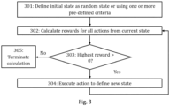
- Figure 3 illustrates, in more detail, an exemplary process according to embodiments for using a reinforcement learning model for determining the UL beams most likely to be optimal for a given set of source terminal devices which share the same optimal DL beam.
- the process of Figure 3 may be carried out by an apparatus (e.g., a computing device).
- the apparatus may be, be comprised in or communicatively connected to an access node (e.g., an access node 104 of Figure 1 ).
- the process of Figure 3 may correspond to a more detailed view of block 203 of Figure 2 for a single reinforcement learning model.
- any of the definitions provided in connection with Figure 2 may apply also here.
- Figure 3 illustrates for simplicity the process for a single reinforcement learning model.
- a separate reinforcement learning model may be provided for each of the plurality of DL beams of the access node (or at least some of them).
- the calculation is the same for all reinforcement learning models with the only difference being the RSRP (or SNR) statistics used (only the RSRP statistics relating to the one or more source terminal devices which considered a particular DL beam as the optimal DL beam are used for a calculation using a reinforcement learning model associated with said DL beam).
- the illustrated process may be carried out either in parallel and/or consecutively for a plurality of reinforcement learning models associated with a plurality of DL beams.
- the apparatus defines, in block 301, an initial state as a random state or using one or more pre-defined criteria, as described above.
- the apparatus calculates, in block 302, for a plurality of actions from said initial state, a plurality of rewards using the reinforcement learning model based on UL SNR statistics of one or more source terminal devices for which the DL beam associated with the reinforcement learning model is the optimal DL beam.
- the plurality of rewards may correspond to rewards associated with actions of adding each UL beam in the secondary beam set to the priority beam set, of removing each UL beam from the priority beam set (and adding them to the secondary beam set) and of doing nothing.
- the calculation of a reward of the plurality of rewards for a given state and a given action of a reinforcement learning model (or equally for a given DL beam), in block 302, may be performed in two steps.
- the apparatus determines SNR statistics for the current state and the new state resulting from performing of the action based on the relevant UL RSRP statistics.
- the relevant UL RSRP statistics for the current state are here UL RSRP statistics relating to the one or more source terminal devices associated with said DL beam and to the UL beam(s) defined by the current state (i.e., the current priority beam set).
- the relevant UL RSRP statistics for the new state are here UL RSRP statistics relating to the one or more source terminal devices associated with said DL beam and to the UL beam(s) defined by the new state (i.e., the new priority beam set).
- the UL RSRP statistics maintained in said at least one memory are effectively filtered based on the information on the one or more source terminal devices (associated with a particular optimal DL beam) and the current and the new state.
- the cumulative distribution functions (CDFs) of the SNR for the current state and the new state may be calculated over all the relevant UL RSRP statistics. From the CDF, the different SNR statistics such as 5th percentile SNR and median SNR may be determined.
- the apparatus calculates the reward based on a change in the UL SNR statistics between the current state and the new state adjusted with the cost for taking the action. This calculation may be carried out, for example, using any of the equations (2), (5) and (6). This two-step process is repeated for each of the plurality of possible actions from said given state though, obviously, the SNR statistics for the current state need to be derived only once for calculating the plurality of rewards.
- the apparatus determines, in block 303, whether the highest reward of the plurality of rewards calculated in block 302 is larger than zero. In other words, it is determined, in block 303, whether or not the action of doing nothing (having a reward of zero) corresponds to the highest reward (implying that all the other actions are associated with zero or negative rewards). If the highest reward is equal to zero, the apparatus determines that it has found the optimal state and thus terminates, in block 305, the calculation process.
- the apparatus executes, in block 304, the action of the plurality of actions associated with the highest reward so as to define a new state.
- the apparatus either adds a new UL beam to the priority beam set or removes a UL beam from the priority beam set in block 304 leading to the new state.
- the calculation of the new state b' n based on the current state b n and the action a i (and index i ) corresponding to the highest reward may be carried out, e.g., according to the equation (1).
- the process pertaining to blocks 302 to 304 is repeated until the highest reward of a plurality of calculated rewards is zero in block 303.
- Figure 4 illustrates a process according to embodiments for performing UL beam selection using beam sweeping (or equally probing) at an access node using the priority beam set (and the secondary beam set) and the associated DL beam.
- the optimal DL beam does not necessarily correspond to the optimal UL beam and thus the selection of the optimal UL beam is not a trivial task.
- the process of Figure 4 may be carried out by an apparatus (e.g., a computing device).
- the apparatus may be, be comprised in or communicatively connected to an access node (e.g., an access node 104 of Figure 1 ).
- the apparatus carrying out the process of Figure 4 may the same or different apparatus compared to the apparatus configured to perform the process of Figure 3 or 4 .
- the apparatus maintains, in block 401, in at least one memory, information on a priority beam set of one or more UL beams of an access node and on a secondary beam set of one or more UL beams of the access node.
- said at least one memory may comprise at least one (internal) memory of the apparatus and/or at least one external memory (i.e., a memory not forming an intrinsic part of the apparatus) such as a memory of an external storage device or a cloud-based memory or storage
- the priority and secondary beam sets are associated with a particular DL beam of the access node.
- the priority beam set may consist of a proper or strict subset of a plurality of UL beams of the access node associated with a particular DL beam of the access node (i.e., not all possible UL beams are in the priority beam set).
- each UL beam provided by the access node may belong to one of the priority and secondary beam sets (and thus only one of the priority and secondary beam sets needs to be explicitly defined assuming that the plurality of UL beams producible by the access node are known).
- Said information on the priority and secondary beam sets may be provided, for example, in the form of a binary vector b n ( n having an integer value within the range 1- N matching said DL beam, where N is the number of the plurality of DL beams provided by the access node), as described in connection with above embodiments.
- the apparatus may maintain, in at least one memory, information on a plurality of priority beam sets of one or more UL beams and on a corresponding plurality of secondary beam sets of one or more UL beams, where each pair of priority and secondary beam sets is associated with a particular DL beam of the access node.
- said information on the plurality of priority and secondary beam sets may be provided, for example, in the form of a set of binary vectors b 1 , b 2 , ... , b N (or a subset thereof), as described in connection with above embodiments.
- the following discussion is limited to beam sweeping associated with a single DL beam for simplicity though obviously the discussed process may be carried out, in general, separately for a plurality of priority and secondary beam sets associated with a respective plurality of DL beams of the access node.
- the apparatus determines, in blocks 402 to 410, an optimal beam for UL reception from one or more terminal devices to which said DL beam is used for transmission by performing the following. Initially, the apparatus causes performing, in block 402, beam sweeping, at the access node, with the one or more terminal devices using the priority beam set (i.e., using each of said one or more UL beams therein in turn). All the UL beams in the priority beam set may be swept before the process proceeds to block 403.
- the beam sweeping may be carried out using any conventional beam sweeping scheme for evaluating received power at the access node using different UL beams.
- the beam sweeping may comprise, for example, scheduling one or more SRS transmissions by at least one of said one or more terminal devices associated with said DL beam.
- the one or more SRSs are measured, at the access node, using one or more different UL beams in the priority beam set, respectively.
- the beam sweeping may comprise changing the UL beam for reception of each PUCCH or PUSCH transmission to match each of the UL beams in the priority beam set in turn.
- the apparatus determines, in block 403, whether a maximum received power measured for the priority beam set is above a first pre-defined power threshold following the completion of the beam sweeping for the priority beam set.
- the first pre-defined power threshold is denoted in Figure 4 as P th,1 . If the first pre-defined power threshold is exceeded, the apparatus selects, in block 404, a UL beam corresponding to the maximum received power measured for the priority beam set as the optimal beam for UL reception.
- the apparatus In response to the maximum received power measured for the priority beam set failing to exceed the first pre-defined power threshold in block 403, the apparatus causes performing, in block 405, beam sweeping, at the access node, with the one or more terminal devices using the secondary beam set (one beam at a time). In other words, the apparatus causes initially performing, in block 405, beam sweeping for a first UL beam of the secondary beam set.
- the apparatus selects, in block 407, said UL beam of the secondary beam set as the optimal beam.
- the beam sweeping of the secondary beam set (and the UL beam selection process in general) is effectively terminated or stopped (before going through all the secondary beams).
- the apparatus In response to a maximum received power measured for the (initial) UL beam in the secondary beam set failing to exceed the first pre-defined power threshold in block 406, the apparatus checks, in block 408, whether all the UL beams in the secondary beam set have been covered. If this is not the case, the apparatus selects, in block 409, the next UL beam from the secondary beam set for beam sweeping. Then, the apparatus repeats actions pertaining to blocks 405 to 408 for the new UL beam.
- the apparatus may terminate, in block 410, the UL beam selection process without selecting an optimal beam for UL reception.
- no UL beam provided by the access node may provide sufficiently high quality connection to the one or more source terminal device associated with a given downlink beam.
- the beam selection as described in connection with Figure 4 has the benefit of reducing resource overhead and latency as the priority beam set may be kept relatively small (relative to the total number of UL beams provided by the access node) and thus quick and easy to probe.
- the apparatus or the access node
- the priority (and secondary) beam set may also be easily updated regularly or periodically.
- the UL beam currently used by the access node may be omitted from the beam sweeping in block 402 or 405 (depending on whether said UL beam belongs to the priority or secondary beam set) as the maximum received power may already be known for said current UL beam.
- the beam selection procedure may be limited to selection from the priority beam set.
- the process may comprise blocks 401 to 404 (with optionally only priority beam set information being maintained in block 401).
- Figure 5 illustrates another process according to embodiments for performing UL beam selection using beam sweeping (or equally probing) at an access node using the priority beam set (and the secondary beam set).
- the process of Figure 5 maybe carried out by an apparatus (e.g., a computing device).
- the apparatus may be, be comprised in or communicatively connected to an access node (e.g., an access node 104 of Figure 1 ).
- the apparatus carrying out the process of Figure 5 may the same or different apparatus compared to the apparatus configured to perform the process of Figure 3 or 4 .
- FIG. 5 corresponds, to a large extent, to the process of Figure 4 .
- blocks 501, 507, 508 may correspond fully to block 401, 403, 404 of Figure 4 .
- the beam sweeping and beam selection based on the secondary beam set may be carried out, in block 509, as described above in connection with blocks 405 to 410 of Figure 4 .
- the blocks are, thus, not discussed here (again) for brevity.
- the apparatus causes performing, in block 502, beam sweeping, at the access node, with one or more terminal devices using the priority beam set (one beam at a time).
- the apparatus causes initially performing, in block 502, beam sweeping for a first UL beam of the priority beam set.
- the apparatus selects, in block 504, said UL beam of the secondary beam set as the optimal beam.
- the second pre-defined power threshold may be defined to be higher than the first pre-defined power threshold (i.e., the power requirement is stricter in this case).
- the second pre-defined power threshold may be defined such that it is expected that even if a better UL beam exists in the priority beam set or the secondary beam set than the one selected based on the second pre-defined power threshold, said better UL beam would be able to provide only marginal benefit (i.e., marginally better gain) compared to the selected UL beam.
- satisfying the second pre-defined power threshold indicates that the UL beam in question is a particularly suitable beam.
- the selection of the UL beam in block 504 effectively terminates or stops the beam sweeping of the priority beam set (before going through all the beams therein).
- the apparatus In response to a maximum received power measured for the (initial) UL beam in the priority beam set failing to exceed the second pre-defined power threshold in block 503, the apparatus checks, in block 505, whether all the UL beams in the priority beam set have been covered. If this is not the case, the apparatus selects, in block 506, the next UL beam from the priority beam set for beam sweeping. Then, the apparatus repeats actions pertaining to blocks 502 to 506 for the new UL beam.
- the apparatus carries out UL beam selection based on the priority beam set as described in connection with blocks 403, 404 of Figure 4 .
- the apparatus determines, in block 507, whether a maximum received power measured for the priority beam set (as a whole) is above a first pre-defined power threshold (defined to be lower than the second pre-defined power threshold) following the completion of the beam sweeping for the priority beam set. It should be noted that the maximum received power measured for the one or more UL beams of the priority beam set as determined in block 507 fails, by necessity, to exceed the second pre-defined power threshold as otherwise the UL beam selection in blocks 503, 504 would have been triggered. If the first pre-defined power threshold is exceeded, the apparatus selects, in block 508, a UL beam corresponding to the maximum received power measured for the priority beam set as the optimal beam for UL reception.
- a first pre-defined power threshold defined to be lower than the second pre-defined power threshold
- the apparatus In response to the maximum received power measured for the priority beam set failing to exceed the first pre-defined power threshold in block 507, the apparatus causes performing, in block 509, beam sweeping and beam selection based on the secondary beam set as discussed previously in connection with Figure 4 , as mentioned above.
- Figure 6 illustrates another alternative process according to embodiments for performing UL beam selection using beam sweeping (or equally probing) at an access node using the priority beam set (and the secondary beam set).
- the process of Figure 6 may be carried out by an apparatus (e.g., a computing device).
- the apparatus may be, be comprised in or communicatively connected to an access node (e.g., an access node 104 of Figure 1 ).
- the apparatus carrying out the process of Figure 6 may the same or different apparatus compared to the apparatus configured to perform the process of any of Figures 3 to 4 .
- the apparatus initially causes, in block 601, the access node to operate using one of the UL beams defined either in the priority beam set or in the secondary beam set. During said operation, the apparatus determines, in block 602, whether one or more pre-defined beam sweeping conditions (i.e., one or more pre-defined conditions for initiating UL beam sweeping) are currently satisfied.
- one or more pre-defined beam sweeping conditions i.e., one or more pre-defined conditions for initiating UL beam sweeping
- Said one or more pre-defined beam sweeping conditions may comprise one or more of the following:
- the pre-defined schedule may define, for example, a period for performing beam sweeping.
- the third pre-defined power threshold may correspond, for example, to the first pre-defined power threshold or the second pre-defined power threshold, as defined in connection with above embodiments.
- the one or more pre-defined criteria for detecting excessively rapid switching (so-called ping-ponging) between two UL beams may comprise, for example, a pre-defined threshold for the time between stopping the use of a particular UL beam and subsequent switching back to using said UL beam and/or a pre-defined threshold for the number of times the access node is allowed to switch directly between two UL beams in a row.
- the apparatus performs, in block 603, the UL beam selection using beam sweeping as described above in connection with Figure 4 or 5 .
- At least one of the one or more pre-defined beam sweeping conditions may be satisfied, in block 602, for example, if beam sweeping is scheduled is to take place at the current time according to said pre-defined schedule, if and. If multiple beam sweeping conditions are defined, only one of them may need to be satisfied for triggering the beam sweeping.
- the apparatus may continue to use the current UL beam (i.e., the process proceeds back to block 601).
- the solution according to embodiments clearly outperforms each of the alternative selection schemes.
- the power loss for not using the best UL beam could be high but not necessarily so high as to considerably degrade the link quality.
- Figure 8 shows the power loss in comparison to not using the best UL beam at every 10 dB SNR bin. Even at low SNR, the solution according to embodiments yields less than 5 dB power loss. If the optimal DL beam is used also as the UL beam in reception, this may result in up to 15 dB loss which may even be enough to cause outages.
- some reinforcement learning models may employ neural networks to, for example, to enable calculation of rewards when the exact dependency between a state and an action and a reward is not known analytically.
- a neural network may be employed also here, instead on analytical solution, for calculating the reward for a given state and action.
- the reward may be defined using a neural network which has been trained with training data comprising sets of state/action pairs and corresponding sets of rewards exhibiting desired behavior.
- the goal of a reinforcement learning may be to learn a policy which maximizes the expected reward or expected cumulative reward.
- the brute-force approach may be employed (i.e., each reward for each action starting from a given state may be calculated, instead of using, e.g., a state-value function for more intelligent exploration).
- Figure 9 illustrates an embodiment of a neural network with one hidden layer
- Figure 10 illustrates an embodiment of a computational node.
- Deep learning also known as deep structured learning or hierarchical learning
- Reinforcement learning which uses a deep neural network (instead of explicitly defining the state space) is commonly called deep reinforcement learning.
- An artificial neural network (ANN) 930 comprises a set of rules that are designed to execute tasks such as regression, classification, clustering, and pattern recognition.
- the ANNs achieve such objectives with a learning procedure, where they are shown various examples of input data, along with the desired output. With this, they learn to identify the proper output for any input within the training data manifold. Learning by using labels is called supervised learning and learning without labels is called unsupervised learning. Deep (reinforcement) learning typically requires a large amount of input data.
- a deep neural network (DNN) 930 is an artificial neural network comprising multiple hidden layers 902 between the input layer 900 and the output layer 914. Training of DNN allows it to find the correct mathematical manipulation to transform the input into the proper output even when the relationship is highly non-linear and/or complicated.
- Each hidden layer 902 comprise nodes 904, 906, 908, 910, 912, where the computation takes place.
- each node 904 combines input data 900 with a set of coefficients, or weights 1000, that either amplify or dampen that input 900, thereby assigning significance to inputs 900 with regard to the task the algorithm is trying to learn.
- the input-weight products are added 1002 and the sum is passed through an activation function 1004, to determine whether and to what extent that signal should progress further through the network 930 to affect the ultimate outcome, such as an act of classification.
- the neural networks learn to recognize correlations between certain relevant features and optimal results.
- the output of deep-learning network 930 may be considered as a likelihood of a particular outcome, such as in this case a probability of decoding success of a data packet.
- the number of layers 902 may vary proportional to the number of used input data 900. However, when the number of input data 900 is high, the accuracy of the outcome 914 is more reliable. On the other hand, when there are fewer layers 902, the computation might take less time and thereby reduce the latency. However, this highly depends on the specific DNN architecture and/or the computational resources.
- Initial weights 1000 of the model can be set in various alternative ways. During the training phase they are adapted to improve the accuracy of the process based on analyzing errors in decision making. Training a model is basically a trial and error activity. In principle, each node 904, 906, 908, 910, 912 of the neural network 930 makes a decision (input ⁇ weight) and then compares this decision to collected data to find out the difference to the collected data. In other words, it determines the error, based on which the weights 1000 are adjusted. Thus, the training of the model may be considered a corrective feedback loop.
- a neural network model is trained using a stochastic gradient descent optimization algorithm for which the gradients are calculated using the backpropagation algorithm.
- the gradient descent algorithm seeks to change the weights 1000 so that the next evaluation reduces the error, meaning the optimization algorithm is navigating down the gradient (or slope) of error. It is also possible to use any other suitable optimization algorithm if it provides sufficiently accurate weights 1000. Consequently, the trained parameters of the neural network 330 may comprise the weights 1000.
- the function used to evaluate a candidate solution i.e., a set of weights
- the objective function is often referred to as a cost function or a loss function.
- any suitable method may be used as a loss function, some examples are mean squared error (MSE), maximum likelihood (MLE), and cross entropy.
- the activation function 1004 of the node 904 it defines the output 914 of that node 904 given an input or set of inputs 900.
- the node 904 calculates a weighted sum of inputs, perhaps adds a bias and then makes a decision as "activate” or “not activate” based on a decision threshold as a binary activation or using an activation function 1004 that gives a nonlinear decision function.
- Any suitable activation function 1004 may be used, for example sigmoid, rectified linear unit (ReLU), normalized exponential function (softmax), sotfplus, tanh, etc.
- the activation function 1004 is usually set at the layer level and applies to all neurons in that layer.
- the output 914 is then used as input for the next node and so on until a desired solution to the original problem is found.
- Figure 11 provides an apparatus 1101 (e.g., a computing device) according to some embodiments.
- Figure 11 may illustrate an apparatus configured to carry out at least the functions described above in connection with deriving priority beam sets for an access node using a reinforcement learning model.
- the apparatus 1101 may comprise one or more communication control circuitry 1120, such as at least one processor, and at least one memory 1130, including one or more algorithms 1131, such as a computer program code (software) wherein the at least one memory and the computer program code (software) are configured, with the at least one processor, to cause, respectively, the apparatus to carry out any one of the exemplified functionalities relating to deriving priority beam sets for an access node using a reinforcement learning model as described above.
- the apparatus 1101 may comprise one or more communication control circuitry 1120, such as at least one processor, and at least one memory 1130, including one or more algorithms 1131, such as a computer program code (software) wherein the at least one memory and the computer program code (software) are configured, with
- the communication control circuitry 1120 of the apparatus 1101 comprises at least reinforcement learning circuitry 1121.
- the authorization circuitry 1121 may be configured to carry out at least some of the functionalities described above by means of any of Figures 2 , 3 , 9 and 10 using one or more individual circuitries.
- the at least one memory 1130 may comprise at least one database 1132 which may comprise, for example, at least UL RSRP statistics for signals measured using a plurality of UL beams of an access node from a plurality of terminal devices and information on optimal DL beams of the access node for transmission to said plurality of terminal devices.
- Each memory 1130 may comprise software and at last one database.
- the memory 1130 may also comprise other databases which may not be related to the functionalities of the apparatus according to any of presented embodiments.
- the at least one memory 1130 may be implemented using any suitable data storage technology, such as semiconductor based memory devices, flash memory, magnetic memory devices and systems, optical memory devices and systems, fixed memory and removable memory.
- the apparatus 1101 may further comprise different interfaces 1110 such as one or more communication interfaces (TX/RX) comprising hardware and/or software for realizing communication connectivity over one or more communications network according to one or more communication protocols.
- the one or more communication interfaces 1110 may provide the apparatus with communication capabilities to communicate in one or more mobile network and enable communication with one or more access nodes, one or more terminal devices (possibly via said plurality of access nodes) and/or one or more other network nodes or elements.
- the one or more communication interfaces 1110 may comprise standard well-known components such as an amplifier, filter, frequency-converter, analog-to-digital converts, (de)modulator, and encoder/decoder circuitries, controlled by the corresponding controlling units, and one or more antennas.
- Figure 12 provides an apparatus 1201 according to some embodiments.
- the apparatus 1201 may be an access node (e.g., the access node 104 of Figure 1 ) or a part thereof.
- the apparatus 1201 may be configured to carry out at least the functions described above in connection with UL beam selection based on priority and secondary beam sets and optionally with deriving priority beam sets for an access node using a reinforcement learning model.
- the apparatus 1201 may comprise one or more communication control circuitry 1220, such as at least one processor, and at least one memory 1230, including one or more algorithms 1231, such as a computer program code (software) wherein the at least one memory and the computer program code (software) are configured, with the at least one processor, to cause, respectively, the apparatus to carry out any one of the exemplified functionalities of the access node described above.
- communication control circuitry 1220 such as at least one processor
- at least one memory 1230 including one or more algorithms 1231, such as a computer program code (software) wherein the at least one memory and the computer program code (software) are configured, with the at least one processor, to cause, respectively, the apparatus to carry out any one of the exemplified functionalities of the access node described above.
- algorithms 1231 such as a computer program code (software) wherein the at least one memory and the computer program code (software) are configured, with the at least one processor, to cause, respectively, the apparatus to carry out any one of the exemp
- the communication control circuitry 1220 of the apparatus comprises at least beam sweeping circuitry 1221.
- the beam sweeping circuitry 1221 may be configured to carry out UL beam selection using beam sweeping according to embodiments and, to this end, to carry out at least some of the functionalities described above by means of any of Figures 4 to 6 using one or more individual circuitries.
- the communication control circuitry 1220 of the apparatus 1201 may optionally also comprise reinforcement learning circuitry 1221.
- the authorization circuitry 1221 may be configured to carry out at least some of the functionalities described above by means of any of Figures 2 , 3 , 9 and 10 using one or more individual circuitries.
- the at least one memory 1230 may comprise at least one database 1232 which may comprise, for example, information on a plurality of priority beam sets associated with a plurality of downlink beams. Each memory 1230 may comprise software and at last one database. The at least one memory 1230 may also comprise other databases which may not be related to the functionalities of the apparatus according to any of presented embodiments.
- the at least one memory 1230 may be implemented using any suitable data storage technology, such as semiconductor based memory devices, flash memory, magnetic memory devices and systems, optical memory devices and systems, fixed memory and removable memory.
- the apparatus may further comprise different interfaces 1210 such as one or more communication interfaces (TX/RX) comprising hardware and/or software for realizing communication connectivity over one or more communications network according to one or more communication protocols.
- the one or more communication interfaces 1210 may provide the apparatus with communication capabilities to enable communication with one or more terminal devices, one or more core network nodes, one or more other access node and/or an apparatus 1101 of Figure 11 .
- the one or more communication interfaces 1210 may comprise standard well-known component(s) such as an amplifier, filter, frequency-converter, analog-to-digital converts, (de)modulator, and encoder/decoder circuitries, controlled by the corresponding controlling units, and/or one or more antennas.
- circuitry' may refer to one or more or all of the following: (a) hardware-only circuit implementations, such as implementations in only analog and/or digital circuitry, and (b) combinations of hardware circuits and software (and/or firmware), such as (as applicable): (i) a combination of analog and/or digital hardware circuit(s) with software/firmware and (ii) any portions of hardware processor(s) with software, including digital signal processor(s), software, and memory(ies) that work together to cause an apparatus, such as a terminal device or an access node, to perform various functions, and (c) hardware circuit(s) and processor(s), such as a microprocessor(s) or a portion of a microprocessor(s), that requires software (e.g.
- circuitry' also covers an implementation of merely a hardware circuit or processor (or multiple processors) or a portion of a hardware circuit or processor and its (or their) accompanying software and/or firmware.
- the term 'circuitry' also covers, for example and if applicable to the particular claim element, a baseband integrated circuit for an access node or a terminal device or other computing or network device.
- the at least one processor, the memory, and the computer program code form processing means or comprises one or more computer program code portions for carrying out one or more operations according to any one of the embodiments of Figures 2 to 6 , 9 and 10 or operations thereof.
- At least some of the processes described in connection with of Figures 2 to 6 , 9 and 10 may be carried out by an apparatus comprising corresponding means for carrying out at least some of the described processes.
- Some example means for carrying out the processes may include at least one of the following: detector, processor (including dual-core and multiple-core processors), digital signal processor, controller, receiver, transmitter, encoder, decoder, memory, RAM, ROM, software, firmware, display, user interface, display circuitry, user interface circuitry, user interface software, display software, circuit, antenna, antenna circuitry, and circuitry.
- the at least one processor, the memory, and the computer program code form processing means or comprises one or more computer program code portions for carrying out one or more operations according to any one of the embodiments of Figures 2 to 6 , 9 and 10 or operations thereof.
- an apparatus e.g., a terminal device or a part thereof comprising means for performing:
- an apparatus e.g., a computing device comprising means for performing:
- the techniques and methods described herein may be implemented by various means. For example, these techniques may be implemented in hardware (one or more devices), firmware (one or more devices), software (one or more modules), or combinations thereof.
- the apparatus(es) of embodiments may be implemented within one or more application-specific integrated circuits (ASICs), digital signal processors (DSPs), digital signal processing devices (DSPDs), programmable logic devices (PLDs), field programmable gate arrays (FPGAs), processors, controllers, micro-controllers, microprocessors, other electronic units designed to perform the functions described herein, or a combination thereof.
- ASICs application-specific integrated circuits
- DSPs digital signal processors
- DSPDs digital signal processing devices
- PLDs programmable logic devices
- FPGAs field programmable gate arrays
- processors controllers, micro-controllers, microprocessors, other electronic units designed to perform the functions described herein, or a combination thereof.
- the implementation can be carried out through modules of at least one chipset (procedures, functions, and so on) that perform the functions described herein.
- the software codes may be stored in a memory unit and executed by processors.
- the memory unit may be implemented within the processor or externally to the processor. In the latter case, it can be communicatively coupled to the processor via various means, as is known in the art.
- the components of the systems described herein may be rearranged and/or complemented by additional components in order to facilitate the achievements of the various aspects, etc., described with regard thereto, and they are not limited to the precise configurations set forth in the given figures, as will be appreciated by one skilled in the art.
- Embodiments as described may also be carried out in the form of a computer process defined by a computer program or portions thereof. Embodiments of the methods described in connection with Figures 2 to 6 , 9 and 10 maybe carried out by executing at least one portion of a computer program comprising corresponding instructions.
- the computer program may be provided as a computer readable medium comprising program instructions stored thereon or as a non-transitory computer readable medium comprising program instructions stored thereon.
- the computer program may be in source code form, object code form, or in some intermediate form, and it may be stored in some sort of carrier, which may be any entity or device capable of carrying the program.
- the computer program may be stored on a computer program distribution medium readable by a computer or a processor.
- the computer program medium may be, for example but not limited to, a record medium, computer memory, read-only memory, electrical carrier signal, telecommunications signal, and software distribution package, for example.
- the computer program medium may be a non-transitory medium. Coding of software for carrying out the embodiments as shown and described is well within the scope of a person of ordinary skill in the art.
- a computer program stored in a computer-readable storage medium comprising software code for performing the steps of: determining an optimal beam for uplink reception from one or more terminal devices for which a downlink beam of an access node is used for transmission by performing the following:
- a computer readable storage medium having a computer program embodied therewith, wherein the computer program executable by a processor to cause the processor to perform a method:
- a computer program product embodied on a distribution medium readable by a computer and comprising program instructions which, when loaded into an apparatus, execute a method comprising: determining an optimal beam for uplink reception from one or more terminal devices for which a downlink beam of an access node is used for transmission by performing the following:
- a computer program stored in a computer-readable storage medium comprising software code for performing the steps of:
- a computer readable storage medium having a computer program embodied therewith, wherein the computer program executable by a processor to cause the processor to perform a method: determining an optimal beam for uplink reception from one or more terminal devices for which a downlink beam of an access node is used for transmission by performing the following:
Applications Claiming Priority (1)
| Application Number | Priority Date | Filing Date | Title |
|---|---|---|---|
| FI20216179 | 2021-11-17 |
Publications (1)
| Publication Number | Publication Date |
|---|---|
| EP4184804A1 true EP4184804A1 (fr) | 2023-05-24 |
Family
ID=84330028
Family Applications (1)
| Application Number | Title | Priority Date | Filing Date |
|---|---|---|---|
| EP22205050.2A Pending EP4184804A1 (fr) | 2021-11-17 | 2022-11-02 | Algorithme pour atténuer l'impact d'une mauvaise correspondance de faisceau de liaison montante/liaison descendante |
Country Status (3)
| Country | Link |
|---|---|
| US (1) | US11647532B1 (fr) |
| EP (1) | EP4184804A1 (fr) |
| CN (1) | CN116137544B (fr) |
Cited By (1)
| Publication number | Priority date | Publication date | Assignee | Title |
|---|---|---|---|---|
| CN117060961A (zh) * | 2023-10-11 | 2023-11-14 | 北京玻色量子科技有限公司 | 一种mimo系统的波束选择方法、装置、介质及设备 |
Citations (2)
| Publication number | Priority date | Publication date | Assignee | Title |
|---|---|---|---|---|
| US20180102827A1 (en) * | 2016-10-12 | 2018-04-12 | Samsung Electronics Co., Ltd. | Apparatus and method for beam search based on antenna configuration in wireless communication system |
| US20200358514A1 (en) * | 2019-05-01 | 2020-11-12 | Qualcomm Incorporated | Beam management using adaptive learning |
Family Cites Families (9)
| Publication number | Priority date | Publication date | Assignee | Title |
|---|---|---|---|---|
| KR102344898B1 (ko) * | 2016-06-15 | 2021-12-30 | 콘비다 와이어리스, 엘엘씨 | 차세대 네트워크들에서의 랜덤 액세스 절차들 |
| US11246143B2 (en) * | 2017-12-15 | 2022-02-08 | Google Llc | Beamforming enhancement via strategic resource utilization |
| US10505616B1 (en) * | 2018-06-01 | 2019-12-10 | Samsung Electronics Co., Ltd. | Method and apparatus for machine learning based wide beam optimization in cellular network |
| JP7193621B2 (ja) * | 2018-09-13 | 2022-12-20 | ノキア ソリューションズ アンド ネットワークス オサケユキチュア | 機械学習を使用してグリッドオブビームを設計するための装置および方法 |
| WO2020259838A1 (fr) * | 2019-06-27 | 2020-12-30 | Apple Inc. | Techniques de formation de faisceau d'équipement utilisateur |
| KR20210112726A (ko) * | 2020-03-06 | 2021-09-15 | 엘지전자 주식회사 | 차량의 좌석별로 대화형 비서를 제공하는 방법 |
| US11923934B2 (en) * | 2020-08-03 | 2024-03-05 | Samsung Electronics Co., Ltd. | Method and apparatus for site-specific and dynamic base station beam codebook design |
| US20220014963A1 (en) * | 2021-03-22 | 2022-01-13 | Shu-Ping Yeh | Reinforcement learning for multi-access traffic management |
| US20210402898A1 (en) * | 2021-09-09 | 2021-12-30 | Intel Corporation | Methods and devices for a vehicle |
-
2022
- 2022-11-02 EP EP22205050.2A patent/EP4184804A1/fr active Pending
- 2022-11-16 US US17/988,402 patent/US11647532B1/en active Active
- 2022-11-16 CN CN202211460187.4A patent/CN116137544B/zh active Active
Patent Citations (2)
| Publication number | Priority date | Publication date | Assignee | Title |
|---|---|---|---|---|
| US20180102827A1 (en) * | 2016-10-12 | 2018-04-12 | Samsung Electronics Co., Ltd. | Apparatus and method for beam search based on antenna configuration in wireless communication system |
| US20200358514A1 (en) * | 2019-05-01 | 2020-11-12 | Qualcomm Incorporated | Beam management using adaptive learning |
Cited By (2)
| Publication number | Priority date | Publication date | Assignee | Title |
|---|---|---|---|---|
| CN117060961A (zh) * | 2023-10-11 | 2023-11-14 | 北京玻色量子科技有限公司 | 一种mimo系统的波束选择方法、装置、介质及设备 |
| CN117060961B (zh) * | 2023-10-11 | 2023-12-26 | 北京玻色量子科技有限公司 | 一种mimo系统的波束选择方法、装置、介质及设备 |
Also Published As
| Publication number | Publication date |
|---|---|
| US20230156765A1 (en) | 2023-05-18 |
| CN116137544A (zh) | 2023-05-19 |
| CN116137544B (zh) | 2024-04-09 |
| US11647532B1 (en) | 2023-05-09 |
Similar Documents
| Publication | Publication Date | Title |
|---|---|---|
| EP3876600B1 (fr) | Optimisation de paramètres de transfert basée sur l'apprentissage par machine | |
| EP3977783B1 (fr) | Contrôle de puissance uplink à l'aide de deep q-learning | |
| WO2021191176A1 (fr) | Production de rapports dans des réseaux sans fil | |
| US20220131625A1 (en) | Selecting Uplink Transmission Band in Wireless Network | |
| US11902806B2 (en) | Machine learning based antenna panel switching | |
| US11797828B2 (en) | Beams to monitor | |
| CN112153658A (zh) | 基于分组错误预测的延迟减少 | |
| WO2020152389A1 (fr) | Apprentissage automatique pour un réseau de communication | |
| WO2020147067A1 (fr) | Détermination de schéma de transmission hybride | |
| US11647532B1 (en) | Algorithm for mitigation of impact of uplink/downlink beam mismatch | |
| US11616582B2 (en) | Neural network-based spatial inter-cell interference learning | |
| EP4044449A1 (fr) | Sélection de faisceau pour des n uds d'accès cellulaire | |
| EP4047382A1 (fr) | Mise à jour de carte d'empreintes digitales rf | |
| EP4195791A1 (fr) | Sélection de paramètres de commande de puissance | |
| US11778565B2 (en) | Determining open loop power control parameters | |
| US11765654B2 (en) | Power saving in radio access network | |
| WO2023144443A1 (fr) | Amélioration de la qualité de connexion après un transfert intercellulaire |
Legal Events
| Date | Code | Title | Description |
|---|---|---|---|
| PUAI | Public reference made under article 153(3) epc to a published international application that has entered the european phase |
Free format text: ORIGINAL CODE: 0009012 |
|
| STAA | Information on the status of an ep patent application or granted ep patent |
Free format text: STATUS: THE APPLICATION HAS BEEN PUBLISHED |
|
| AK | Designated contracting states |
Kind code of ref document: A1 Designated state(s): AL AT BE BG CH CY CZ DE DK EE ES FI FR GB GR HR HU IE IS IT LI LT LU LV MC ME MK MT NL NO PL PT RO RS SE SI SK SM TR |
|
| STAA | Information on the status of an ep patent application or granted ep patent |
Free format text: STATUS: REQUEST FOR EXAMINATION WAS MADE |
|
| 17P | Request for examination filed |
Effective date: 20231124 |
|
| RBV | Designated contracting states (corrected) |
Designated state(s): AL AT BE BG CH CY CZ DE DK EE ES FI FR GB GR HR HU IE IS IT LI LT LU LV MC ME MK MT NL NO PL PT RO RS SE SI SK SM TR |