EP4195791A1 - Sélection de paramètres de commande de puissance - Google Patents
Sélection de paramètres de commande de puissance Download PDFInfo
- Publication number
- EP4195791A1 EP4195791A1 EP22209616.6A EP22209616A EP4195791A1 EP 4195791 A1 EP4195791 A1 EP 4195791A1 EP 22209616 A EP22209616 A EP 22209616A EP 4195791 A1 EP4195791 A1 EP 4195791A1
- Authority
- EP
- European Patent Office
- Prior art keywords
- radio access
- power control
- access network
- uplink power
- parameters
- Prior art date
- Legal status (The legal status is an assumption and is not a legal conclusion. Google has not performed a legal analysis and makes no representation as to the accuracy of the status listed.)
- Pending
Links
- 238000013528 artificial neural network Methods 0.000 claims abstract description 67
- 238000012549 training Methods 0.000 claims abstract description 20
- 230000000694 effects Effects 0.000 claims abstract description 11
- 238000000034 method Methods 0.000 claims description 27
- 230000015654 memory Effects 0.000 claims description 21
- 238000004590 computer program Methods 0.000 claims description 20
- 238000012544 monitoring process Methods 0.000 claims 1
- 210000004027 cell Anatomy 0.000 description 34
- 230000006870 function Effects 0.000 description 32
- 238000004891 communication Methods 0.000 description 30
- 230000005540 biological transmission Effects 0.000 description 12
- 238000005516 engineering process Methods 0.000 description 10
- 230000008569 process Effects 0.000 description 10
- 230000004913 activation Effects 0.000 description 9
- 238000004422 calculation algorithm Methods 0.000 description 9
- 238000012545 processing Methods 0.000 description 8
- 238000007726 management method Methods 0.000 description 6
- 230000006855 networking Effects 0.000 description 6
- 238000004088 simulation Methods 0.000 description 6
- 238000005457 optimization Methods 0.000 description 5
- 238000012360 testing method Methods 0.000 description 5
- 238000013135 deep learning Methods 0.000 description 4
- 230000001413 cellular effect Effects 0.000 description 3
- 238000009826 distribution Methods 0.000 description 3
- 230000000670 limiting effect Effects 0.000 description 3
- 238000007476 Maximum Likelihood Methods 0.000 description 2
- 238000013459 approach Methods 0.000 description 2
- 230000003190 augmentative effect Effects 0.000 description 2
- 230000008859 change Effects 0.000 description 2
- 238000013500 data storage Methods 0.000 description 2
- 230000007423 decrease Effects 0.000 description 2
- 238000013461 design Methods 0.000 description 2
- 238000004519 manufacturing process Methods 0.000 description 2
- 238000010295 mobile communication Methods 0.000 description 2
- 238000013442 quality metrics Methods 0.000 description 2
- 230000011664 signaling Effects 0.000 description 2
- 238000001228 spectrum Methods 0.000 description 2
- 241001465754 Metazoa Species 0.000 description 1
- 230000002776 aggregation Effects 0.000 description 1
- 238000004220 aggregation Methods 0.000 description 1
- 238000004458 analytical method Methods 0.000 description 1
- 230000002567 autonomic effect Effects 0.000 description 1
- 230000006399 behavior Effects 0.000 description 1
- 230000009286 beneficial effect Effects 0.000 description 1
- 230000008901 benefit Effects 0.000 description 1
- 239000000969 carrier Substances 0.000 description 1
- 230000000295 complement effect Effects 0.000 description 1
- 238000012937 correction Methods 0.000 description 1
- 230000001419 dependent effect Effects 0.000 description 1
- 238000011161 development Methods 0.000 description 1
- 238000011156 evaluation Methods 0.000 description 1
- 230000014509 gene expression Effects 0.000 description 1
- 230000010354 integration Effects 0.000 description 1
- 230000003993 interaction Effects 0.000 description 1
- 230000001788 irregular Effects 0.000 description 1
- 230000007774 longterm Effects 0.000 description 1
- 238000010801 machine learning Methods 0.000 description 1
- 238000005259 measurement Methods 0.000 description 1
- 230000007246 mechanism Effects 0.000 description 1
- 238000003062 neural network model Methods 0.000 description 1
- 210000002569 neuron Anatomy 0.000 description 1
- 238000003909 pattern recognition Methods 0.000 description 1
- 238000012913 prioritisation Methods 0.000 description 1
- 230000002829 reductive effect Effects 0.000 description 1
- 230000004044 response Effects 0.000 description 1
- 230000000717 retained effect Effects 0.000 description 1
- 230000002441 reversible effect Effects 0.000 description 1
- 230000035945 sensitivity Effects 0.000 description 1
- 230000007727 signaling mechanism Effects 0.000 description 1
- 230000003068 static effect Effects 0.000 description 1
- 238000012546 transfer Methods 0.000 description 1
- 238000010200 validation analysis Methods 0.000 description 1
- 230000003936 working memory Effects 0.000 description 1
Images


Classifications
-
- H—ELECTRICITY
- H04—ELECTRIC COMMUNICATION TECHNIQUE
- H04W—WIRELESS COMMUNICATION NETWORKS
- H04W52/00—Power management, e.g. TPC [Transmission Power Control], power saving or power classes
- H04W52/04—TPC
- H04W52/06—TPC algorithms
- H04W52/14—Separate analysis of uplink or downlink
- H04W52/146—Uplink power control
-
- H—ELECTRICITY
- H04—ELECTRIC COMMUNICATION TECHNIQUE
- H04W—WIRELESS COMMUNICATION NETWORKS
- H04W52/00—Power management, e.g. TPC [Transmission Power Control], power saving or power classes
- H04W52/04—TPC
- H04W52/18—TPC being performed according to specific parameters
-
- H—ELECTRICITY
- H04—ELECTRIC COMMUNICATION TECHNIQUE
- H04W—WIRELESS COMMUNICATION NETWORKS
- H04W52/00—Power management, e.g. TPC [Transmission Power Control], power saving or power classes
- H04W52/04—TPC
- H04W52/18—TPC being performed according to specific parameters
- H04W52/22—TPC being performed according to specific parameters taking into account previous information or commands
- H04W52/225—Calculation of statistics, e.g. average, variance
-
- H—ELECTRICITY
- H04—ELECTRIC COMMUNICATION TECHNIQUE
- H04W—WIRELESS COMMUNICATION NETWORKS
- H04W52/00—Power management, e.g. TPC [Transmission Power Control], power saving or power classes
- H04W52/04—TPC
- H04W52/18—TPC being performed according to specific parameters
- H04W52/24—TPC being performed according to specific parameters using SIR [Signal to Interference Ratio] or other wireless path parameters
- H04W52/242—TPC being performed according to specific parameters using SIR [Signal to Interference Ratio] or other wireless path parameters taking into account path loss
-
- G—PHYSICS
- G06—COMPUTING; CALCULATING OR COUNTING
- G06N—COMPUTING ARRANGEMENTS BASED ON SPECIFIC COMPUTATIONAL MODELS
- G06N3/00—Computing arrangements based on biological models
- G06N3/02—Neural networks
- G06N3/04—Architecture, e.g. interconnection topology
- G06N3/048—Activation functions
-
- G—PHYSICS
- G06—COMPUTING; CALCULATING OR COUNTING
- G06N—COMPUTING ARRANGEMENTS BASED ON SPECIFIC COMPUTATIONAL MODELS
- G06N3/00—Computing arrangements based on biological models
- G06N3/02—Neural networks
- G06N3/04—Architecture, e.g. interconnection topology
- G06N3/0499—Feedforward networks
-
- G—PHYSICS
- G06—COMPUTING; CALCULATING OR COUNTING
- G06N—COMPUTING ARRANGEMENTS BASED ON SPECIFIC COMPUTATIONAL MODELS
- G06N3/00—Computing arrangements based on biological models
- G06N3/02—Neural networks
- G06N3/08—Learning methods
- G06N3/084—Backpropagation, e.g. using gradient descent
-
- G—PHYSICS
- G06—COMPUTING; CALCULATING OR COUNTING
- G06N—COMPUTING ARRANGEMENTS BASED ON SPECIFIC COMPUTATIONAL MODELS
- G06N3/00—Computing arrangements based on biological models
- G06N3/02—Neural networks
- G06N3/08—Learning methods
- G06N3/09—Supervised learning
-
- H—ELECTRICITY
- H04—ELECTRIC COMMUNICATION TECHNIQUE
- H04W—WIRELESS COMMUNICATION NETWORKS
- H04W52/00—Power management, e.g. TPC [Transmission Power Control], power saving or power classes
- H04W52/04—TPC
- H04W52/06—TPC algorithms
- H04W52/10—Open loop power control
Definitions
- the exemplary and non-limiting embodiments of the invention relate generally to wireless communication systems.
- the exemplary and non-limiting embodiments of the invention relate especially to apparatuses and methods in wireless communication networks.
- control of transmission power is an important factor. Wireless transmission of the mobile terminals and network elements typically cause interference to other transmissions of the network. Further, power consumption is a significant factor in mobile terminals which are battery-operated. However, transmission power should not be too low as the transmission quality of the wireless connections might decrease. Thus, efficient power control mechanisms are constantly developed.
- Some embodiments of the present invention are applicable to a user terminal, a communication device, a base station, eNodeB, gNodeB, a distributed realisation of a base station, a network element of a communication system, a corresponding component, and/or to any communication system or any combination of different communication systems that support required functionality.
- UMTS universal mobile telecommunications system
- UTRAN wireless local area network
- WiFi wireless local area network
- WiMAX worldwide interoperability for microwave access
- Bluetooth ® personal communications services
- PCS personal communications services
- WCDMA wideband code division multiple access
- UWB ultra-wideband
- sensor networks sensor networks
- MANETs mobile ad-hoc networks
- IMS Internet Protocol multimedia subsystems
- Fig. 1 depicts examples of simplified system architectures only showing some elements and functional entities, all being logical units, whose implementation may differ from what is shown.
- the connections shown in Fig. 1 are logical connections; the actual physical connections may be different. It is apparent to a person skilled in the art that the system typically comprises also other functions and structures than those shown in Fig. 1 .
- Fig. 1 shows a part of an exemplifying radio access network.
- Fig. 1 shows devices 100 and 102.
- the devices 100 and 102 are configured to be in a wireless connection on one or more communication channels with a node 104.
- the node 104 is further connected to a core network 106.
- the node 104 may be an access node such as (e/g)NodeB serving devices in a cell.
- the node 104 may be a non-3GPP access node.
- the physical link from a device to a (e/g)NodeB is called uplink or reverse link and the physical link from the (e/g)NodeB to the device is called downlink or forward link.
- (e/g)NodeBs or their functionalities may be implemented by using any node, host, server or access point etc. entity suitable for such a usage.
- a communications system typically comprises more than one (e/g)NodeB in which case the (e/g)NodeBs may also be configured to communicate with one another over links, wired or wireless, designed for the purpose. These links may be used for signalling purposes.
- the (e/g)NodeB is a computing device configured to control the radio resources of communication system it is coupled to.
- the NodeB may also be referred to as a base station, an access point or any other type of interfacing device including a relay station capable of operating in a wireless environment.
- the (e/g)NodeB includes or is coupled to transceivers. From the transceivers of the (e/g)NodeB, a connection is provided to an antenna unit that establishes bi-directional radio links to devices.
- the antenna unit may comprise a plurality of antennas or antenna elements.
- the (e/g)NodeB is further connected to the core network 106 (CN or next generation core NGC). Depending on the deployed technology, the (e/g)NodeB is connected to a serving and packet data network gateway (S-GW +P-GW) or user plane function (UPF), for routing and forwarding user data packets and for providing connectivity of devices to one ore more external packet data networks, and to a mobile management entity (MME) or access mobility management function (AMF), for controlling access and mobility of the devices.
- S-GW +P-GW serving and packet data network gateway
- UPF user plane function
- MME mobile management entity
- AMF access mobility management function
- Exemplary embodiments of a device are a subscriber unit, a user device, a user equipment (UE), a user terminal, a terminal device, a mobile station, a mobile device, etc
- the device typically refers to a mobile or static device (e.g. a portable or non-portable computing device) that includes wireless mobile communication devices operating with or without an universal subscriber identification module (USIM), including, but not limited to, the following types of devices: mobile phone, smartphone, personal digital assistant (PDA), handset, device using a wireless modem (alarm or measurement device, etc.), laptop and/or touch screen computer, tablet, game console, notebook, and multimedia device.
- a device may also be a nearly exclusive uplink only device, of which an example is a camera or video camera loading images or video clips to a network.
- a device may also be a device having capability to operate in Internet of Things (IoT) network which is a scenario in which objects are provided with the ability to transfer data over a network without requiring human-to-human or human-to-computer interaction, e.g. to be used in smart power grids and connected vehicles.
- IoT Internet of Things
- the device may also utilise cloud.
- a device may comprise a user portable device with radio parts (such as a watch, earphones or eyeglasses) and the computation is carried out in the cloud.
- the device illustrates one type of an apparatus to which resources on the air interface are allocated and assigned, and thus any feature described herein with a device may be implemented with a corresponding apparatus, such as a relay node.
- a relay node is a layer 3 relay (self-backhauling relay) towards the base station.
- the device (or in some embodiments a layer 3 relay node) is configured to perform one or more of user equipment functionalities.
- CPS cyber-physical system
- ICT interconnected information and communications technology
- devices sensors, actuators, processors microcontrollers, etc.
- mobile cyber physical systems in which the physical system in question has inherent mobility, are a subcategory of cyber-physical systems. Examples of mobile physical systems include mobile robotics and electronics transported by humans or animals.
- apparatuses have been depicted as single entities, different units, processors and/or memory units (not all shown in Fig. 1 ) may be implemented.
- 5G enables using multiple input - multiple output (MIMO) antennas, many more base stations or nodes than the LTE (a so-called small cell concept), including macro sites operating in co-operation with smaller stations and employing a variety of radio technologies depending on service needs, use cases and/or spectrum available.
- 5G mobile communications supports a wide range of use cases and related applications including video streaming, augmented reality, different ways of data sharing and various forms of machine type applications (such as (massive) machine-type communications (mMTC), including vehicular safety, different sensors and real-time control.
- 5G is expected to have multiple radio interfaces, e.g. below 6GHz or above 24 GHz, cmWave and mmWave, and also being integrable with existing legacy radio access technologies, such as the LTE.
- Integration with the LTE may be implemented, at least in the early phase, as a system, where macro coverage is provided by the LTE and 5G radio interface access comes from small cells by aggregation to the LTE.
- 5G is planned to support both inter-RAT operability (such as LTE-5G) and inter-RI operability (inter-radio interface operability, such as below 6GHz - cmWave, 6 or above 24 GHz - cmWave and mmWave).
- inter-RAT operability such as LTE-5G
- inter-RI operability inter-radio interface operability, such as below 6GHz - cmWave, 6 or above 24 GHz - cmWave and mmWave.
- One of the concepts considered to be used in 5G networks is network slicing in which multiple independent and dedicated virtual sub-networks (network instances) may be created within the same infrastructure to run services that have different requirements on latency, reliability, throughput and mobility.
- the current architecture in LTE networks is fully distributed in the radio and fully centralized in the core network.
- the low latency applications and services in 5G require to bring the content close to the radio which leads to local break out and multi-access edge computing (MEC).
- MEC multi-access edge computing
- 5G enables analytics and knowledge generation to occur at the source of the data. This approach requires leveraging resources that may not be continuously connected to a network such as laptops, smartphones, tablets and sensors.
- MEC provides a distributed computing environment for application and service hosting. It also has the ability to store and process content in close proximity to cellular subscribers for faster response time.
- Edge computing covers a wide range of technologies such as wireless sensor networks, mobile data acquisition, mobile signature analysis, cooperative distributed peer-to-peer ad hoc networking and processing also classifiable as local cloud/fog computing and grid/mesh computing, dew computing, mobile edge computing, cloudlet, distributed data storage and retrieval, autonomic self-healing networks, remote cloud services, augmented and virtual reality, data caching, Internet of Things (massive connectivity and/or latency critical), critical communications (autonomous vehicles, traffic safety, real-time analytics, time-critical control, healthcare applications).
- the communication system is also able to communicate with other networks 112, such as a public switched telephone network, or a VoIP network, or the Internet, or a private network, or utilize services provided by them.
- the communication network may also be able to support the usage of cloud services, for example at least part of core network operations may be carried out as a cloud service (this is depicted in Fig. 1 by "cloud" 114).
- the communication system may also comprise a central control entity, or a like, providing facilities for networks of different operators to cooperate for example in spectrum sharing.
- Edge cloud may be brought into a radio access network (RAN) by utilizing network function virtualization (NFV) and software defined networking (SDN).
- RAN radio access network
- NFV network function virtualization
- SDN software defined networking
- Using the technology of edge cloud may mean access node operations to be carried out, at least partly, in a server, host or node operationally coupled to a remote radio head or base station comprising radio parts. It is also possible that node operations will be distributed among a plurality of servers, nodes or hosts.
- Application of cloudRAN architecture enables RAN real time functions being carried out at or close to a remote antenna site (in a distributed unit, DU 108) and non-real time functions being carried out in a centralized manner (in a centralized unit, CU 110).
- 5G may also utilize satellite communication to enhance or complement the coverage of 5G service, for example by providing backhauling.
- Possible use cases are providing service continuity for machine-to-machine (M2M) or Internet of Things (IoT) devices or for passengers on board of vehicles, Mobile Broadband, (MBB) or ensuring service availability for critical communications, and future railway/maritime/aeronautical communications.
- Satellite communication may utilise geostationary earth orbit (GEO) satellite systems, but also low earth orbit (LEO) satellite systems, in particular mega-constellations (systems in which hundreds of (nano)satellites are deployed).
- GEO geostationary earth orbit
- LEO low earth orbit
- mega-constellations systems in which hundreds of (nano)satellites are deployed.
- Each satellite in the mega-constellation may cover several satellite-enabled network entities that create on-ground cells.
- the on-ground cells may be created through an on-ground relay node or by a gNB located on-ground or in
- the depicted system is only an example of a part of a radio access system and in practice, the system may comprise a plurality of (e/g)NodeBs, the device may have an access to a plurality of radio cells and the system may comprise also other apparatuses, such as physical layer relay nodes or other network elements, etc. At least one of the (e/g)NodeBs or may be a Home(e/g)nodeB. Additionally, in a geographical area of a radio communication system a plurality of different kinds of radio cells as well as a plurality of radio cells may be provided.
- Radio cells may be macro cells (or umbrella cells) which are large cells, usually having a diameter of up to tens of kilometers, or smaller cells such as micro-, femto- or picocells.
- the (e/g)NodeBs of Fig. 1 may provide any kind of these cells.
- a cellular radio system may be implemented as a multilayer network including several kinds of cells. Typically, in multilayer networks, one access node provides one kind of a cell or cells, and thus a plurality of (e/g)NodeBs are required to provide such a network structure.
- a network which is able to use “plug-and-play" (e/g)Node Bs includes, in addition to Home (e/g)NodeBs (H(e/g)nodeBs), a home node B gateway, or HNB-GW (not shown in Fig. 1 ).
- HNB-GW HNB Gateway
- a HNB Gateway (HNB-GW) which is typically installed within an operator's network may aggregate traffic from a large number of HNBs back to a core network.
- Fig.2 illustrates an example of a communication system based on 5G network components.
- a terminal device, user terminal or user equipment 200 communicating via a 5G network 202 with a data network 112.
- the user terminal 200 is connected to a Radio Access Network RAN node, such as (e/g)NodeB 206 which provides the user terminal with a connection to the network 112 via one or more User Plane Functions, UPF 208.
- the user terminal 200 is further connected to Core Access and Mobility Management Function, AMF 210, which is a control plane core connector for (radio) access network and can be seen from this perspective as the 5G version of Mobility Management Entity, MME, in LTE.
- AMF 210 Core Access and Mobility Management Function
- the 5G network further comprises Session Management Function, SMF 212, which is responsible for subscriber sessions, such as session establishment, modify and release, and a Policy Control Function, PCF 214 which is configured to govern network behavior by providing policy rules to control plane functions.
- SMF 212 Session Management Function
- PCF 214 Policy Control Function
- the 5G network may further comprise a location management function, LMF 216, which may be configured to determine the location of the terminal device 200 based on information received from the terminal device and/or gNB 206.
- uplink PC user equipment power control
- Tx transmission
- UE battery power may be saved.
- Equation (1) illustrates how Physical Uplink Shared Channel (PUSCH) transmission power is set based on the signalled control parameters.
- P PUSCH min P max , P 0 + ⁇ PL + 10 log 10 M 2 ⁇ + ⁇ TF , where P PUSCH is transmission power of PUSCH (unit dBm), P max is maximum transmission power of the device (unit dBm), P 0 is target received power (unit dBm), ⁇ is fractional pathloss compensation factor, where value 1.0 means that pathloss is fully compensated, PL is pathloss from the user equipment to the base station (unit dB), ⁇ is subcarrier spacing related parameter, M is number of resource blocks scheduled for transmission and ⁇ TF is modulation and coding scheme related parameter.
- the 5G specification supports also some enhancements for basic uplink power control (UL PC), for example closed loop correction part and possibility for dedicated UE-specific PC commands.
- UL PC uplink power control
- the power control parameters are signalled with RRC signalling.
- the parameters are typically cell-specific, i.e., they are broadcasted per cell and hence can be different between different cells.
- URLLC ultra-reliable low-latency communication
- eMBB enhanced mobile broadband
- KPIs key performance indicators
- the flowchart of Fig. 3A illustrates an embodiment.
- the flowchart illustrates an example of the operation of an apparatus or entity configured to train a neural network.
- the apparatus is configured to determine, from a given set of radio access network parameters, a selection of radio access network parameters which have an effect on uplink power control.
- the apparatus is configured to train a neural network to determine uplink power control parameters, utilising as an input the selection of radio access network parameters, more than one radio access network configuration, one or more types of radio access network traffic and varying radio access network conditions.
- step 304 the apparatus is configured to utilise the trained neural network, with as an input the selection of radio access network parameters, to obtain as an output as set of initial uplink power control parameters.
- the uplink power control parameters comprise target received power P 0 , and a fractional pathloss compensation factor ⁇ .
- the apparatus is configured to transmit the set of initial uplink power control parameters to further processing.
- the flowchart of Fig. 3B illustrates an embodiment.
- the flowchart illustrates an example of the operation of an apparatus such as a base station or a gNB.
- the apparatus is configured to receive a set of initial uplink power control parameters trained by a neural network.
- the apparatus is configured to utilise the set of initial uplink power control parameters in an operating radio access network and select from the set the parameters giving best performance as the uplink power control parameters to be applied in the radio access network.
- the network element when utilising the set of initial uplink power control parameters in an operating radio access network, may be configured to apply each uplink power control parameter of the set a predetermined amount of time.
- the network element when utilising the set of initial uplink power control parameters in an operating radio access network, may be configured to monitor the performance of the network, and if the performance deteriorates, reject the current uplink power control parameters and apply utilise of the different parameters from the set of initial uplink power control parameters.
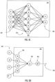
- FIG. 3C illustrates an embodiment of the neural network 320 with one hidden layer
- FIG. 3D illustrates an embodiment of a computational node.
- Deep learning also known as deep structured learning or hierarchical learning, is part of a broader family of machine learning methods based on the layers used in artificial neural networks.
- An artificial neural network comprises a set of rules that are designed to execute tasks such as regression, classification, clustering, and pattern recognition.
- the ANNs achieve such objectives with a learning procedure, where they are shown various examples of input data, along with the desired output. With this, they learn to identify the proper output for any input within the training data manifold. Learning by using labels is called supervised learning and learning without labels is called unsupervised learning. Deep learning typically requires a large amount of input data.
- a deep neural network (DNN) 320 is an artificial neural network comprising a given number of hidden layers 324 between the input layer 322 and the output layer 326. Training of the neural network allows it to find the correct mathematical manipulation to transform the input into the proper output even when the relationship is highly non-linear and/or complicated.
- each hidden layer 324 comprise nodes 328, 330, 332, 4334, 336, where the computation takes place.
- each node 336 combines input data 322 with a set of coefficients, or weights 340, that either amplify or dampen that input 322, thereby assigning significance to inputs 322 with regard to the task the algorithm is trying to learn.
- the input-weight products are added 342 and the sum is passed through an activation function 344, to determine whether and to what extent that signal should progress further through the network 320 to affect the ultimate outcome, such as an act of classification.
- the neural networks learn to recognize correlations between certain relevant features and optimal results.
- the output of deep-learning network 332 may be considered as a likelihood of a particular outcome, such as in this case a probability of given PC parameter being optimal.
- the number of hidden layers 324 may vary proportional to the number of used input data 322. However, when the number of input data 322 is high, the accuracy of the outcome 326 is more reliable. On the other hand, when there are fewer layers 324, the computation might take less time and thereby reduce the latency. However, this highly depends on the specific neural network architecture and/or the computational resources.
- Initial weights 340 of the model can be set in various alternative ways. During the training phase they are adapted to improve the accuracy of the process based on analyzing errors in decision making. Training a model is basically a trial-and-error activity. In principle, each node 328, 330, 332, 4334, 336 of the neural network 320 makes a decision (input*weight) and then compares this decision to collected data to find out the difference to the collected data. In other words, it determines the error, based on which the weights 340 are adjusted. Thus, the training of the model may be considered a corrective feedback loop.
- a neural network model is trained using a stochastic gradient descent optimization algorithm for which the gradients are calculated using the backpropagation algorithm.
- the gradient descent algorithm seeks to change the weights 340 so that the next evaluation reduces the error, meaning the optimization algorithm is navigating down the gradient (or slope) of error. It is also possible to use any other suitable optimization algorithm if it provides sufficiently accurate weights 340. Consequently, the trained parameters of the neural network 320 may comprise the weights 340.
- the function used to evaluate a candidate solution i.e. a set of weights
- the objective function is often referred to as a cost function or a loss function.
- any suitable method may be used as a loss function, some examples are mean squared error (MSE), maximum likelihood (MLE), and cross entropy.
- the activation function 344 of the node 336 defines the output 326 of that node 336 given an input or set of inputs 322.
- the node 336 calculates a weighted sum of inputs, perhaps adds a bias and then makes a decision as "activate” or “not activate” based on a decision threshold as a binary activation or using an activation function 344 that gives a nonlinear decision function.
- Any suitable activation function 344 may be used, for example sigmoid, rectified linear unit (ReLU), normalized exponential function (softmax), sotfplus, tanh, etc.
- the activation function 344 is usually set at the layer level and applies to all neurons in that layer.
- the output 326 is then used as input for the next node and so on until a desired solution to the original problem is found.
- Fig. 4 illustrates an example realisation of step 300 where selection of radio access network parameters is determined.
- radio access network parameters 400 are chosen as a starting point. These network parameters may be assumed to be such network parameters that might affect to power control parameters.
- the given set of radio access network parameters comprise two or more of base station positions, estimated path loss exponent, cell-specific loads, inter site distance, average number of users per cell, network center frequency and average packet size.
- radio access network parameters 400 are fed to a simulator 402 where the radio access network parameters and power control parameters 404 are simulated under different values for the chosen parameters 400 to see which of them impacts the power control parameters.
- the simulation is automatically monitored 406 and power control parameters are evaluated with predefined key performance indicators (KPIs).
- KPIs key performance indicators
- Fig. 5 illustrates an example realisation of the step 302 where a neural network is trained to determine uplink power control parameters.
- the uplink power control parameters comprise the target received power P 0 , and the fractional pathloss compensation factor ⁇ .
- the uplink power control parameters comprise the target received power P 0 , and the fractional pathloss compensation factor ⁇ .
- other parameters may be considered as one skilled in the art is well aware.
- training data may be generated by simulating a network with eMBB traffic.
- eMBB traffic Several different network configurations may be used, and each of them evaluated with all combinations of P 0 and ⁇ . Both of these parameters are discrete parameters. This way, it is possible to evaluate otherwise identical networks with different power control parameters, and consequently determine the optimal power control parameters for each network type.
- the PC parameters which give the highest value for S are considered optimal for the given network configuration.
- the above metric S is an example of possible metrics. It is possible to choose also any other metric for defining the optimal network operation. The metric may be chosen based on the type of traffic the network operates under. For instance, in URLLC scenarios the latency should be reflected in the equation.
- ISD may be used an input since the uplink PC operation depends heavily on the distance between the user equipment and the base station.
- the balance between users at the cell edge and at cell center is crucial for the overall performance. For example, with smaller ⁇ value less compensation is given for increased pathloss which leads to smaller received power from cell edge users but on the other hand the cell edge users also cause less interference to neighbouring base station. This balance depends on ISD which impacts both the pathloss for the user but also how much interference the user generates to neighbouring cell.
- the effect of load on PC parameters comes via multitude of network effects.
- the load affects the scheduling and the amount of resource blocks allocated to UEs, which impact the power available for each resource block.
- MCS modulation and coding scheme
- the input may also be normalized to have unit variance before feeding it to the neural network. It may be noted that considerably more parameters may be fed to the neural network, but in this simplified example only two parameters are considered.
- Other potential input parameters include path loss exponent, base station positions, and cell-specific loads.
- each (P 0 , ⁇ ) pair may be encoded into a numerical class indicator, and therefore the neural network essentially outputs probabilities for the optimality of the different PC parameter pairs. The one with the highest probability is typically chosen as the classification result.
- the training itself may be carried out by collecting the simulation data into a data storage 500. Each data sample represents an input-output pair, where the input is the chosen data vector, and the output is the optimal PC parameter pair.
- the collected data is split 502 into separate portions, one of which is used for training 504, and one of which is used for validating 506 the neural network's performance.
- the training loop 508 involves first feeding a batch of input samples through the neural network, after which the predicted class is mapped to their corresponding PC parameter values 510, and the loss with respect to the optimal PC parameter values is calculated 512. For instance, log-likelihood loss can be used to determine the value of the loss.
- the parameters of the neural network are then updated based on the calculated loss using stochastic gradient descent, or any of its variants.
- Fig. 6 illustrates an example of providing the initial uplink power control parameters.
- radio access network parameters 600 is taken as an input to the trained neural network 602, which is configured to determine 604 initial uplink power control parameters, in this example P 0 , and ⁇ .
- a neural network comprises an input layer, a number of hidden layers and an output layer.
- a four-layer neural network is used for determining initial uplink power control parameters.
- other number of layers may be used as well.
- the neural network comprises four layers in total, where the hidden layers utilize the rectified linear unit (ReLU) as activation function, and the output layer is fed through a sigmoid function to map the output to class probabilities.
- ReLU rectified linear unit
- Table 1 illustrates the used neural network, to carry out the initial PC parameter prediction. It may be noted that shown values are merely an example of possible structure of the neural network. Table 1 Layer Input size Output size Activation Fully connected 2 50 ReLU Fully connected 50 50 ReLU Fully connected 50 50 ReLU Fully connected 50 9 Sigmoid
- the gain of the NN-based prediction is evident: on average, it can increase the total throughput of the cell by 60%, while doubling the cell edge throughput.
- the predicted PC parameters are beneficial for most network configurations. These simulation results show the benefit of the proposed approach. When investigating the classification accuracy of the trained neural network, it predicts the PC parameters correctly 65-80% of the time for the randomly chosen test data set, demonstrating high accuracy in choosing the optimal PC parameter pair.
- the packet size affects how many resource blocks are utilized in the transmission protocol. Increasing the amount of resource blocks increases the power level requirement and therefore different power control parameters are needed.
- pathloss coefficients are from the fact that path loss is compensated with power control parameters and therefore it directly affects the transmit power. Too low transmit power means low bitrates especially for cell edge users. Pathloss varies in different environments, for example in city and countryside. Therefore, pathloss coefficients give information about environment.
- Table 4 Mean throughput gain (avg.) Edge throughput gain (avg.) L3 delay gain (avg.) Gain 1.4 1.9 1.9
- Fig. 7 illustrates an example of possible method for finetuning the parameters.
- radio access network parameters 600 is taken as an input to the trained neural network 602, which is configured to produce as an output the initial uplink power control parameters with probabilities 700.
- the parameters are parameter pair P 0 , and ⁇ .
- An unused power control parameter pair having the highest probability is selected 702.
- the probability is tested 704 against some preselected threshold value. If the probability is smaller than the threshold the process is terminated 706. Otherwise, the parameter pair is taken into use 708 and the network is operated 710 and performance of the network is tracked. Performance metrics are calculated 712 and compared 714 to metrics obtained earlier (using other parameters). If performance is higher, the present parameters are retained 716, and process continues in step 702. If not, earlier parameters, which gave better performance, are taken 718 into use. This procedure may be repeated as long as there are PC parameter candidates with probabilities higher than the threshold.
- the process comprises also a safeguard in that if the performance of the system suddenly decreases 720, earlier parameters are taken 718 into use. This ensures robustness against erroneous PC parameter predictions.
- FIGS. 8A, 8B and 8C illustrate an embodiment.
- the figures illustrate a simplified example of an apparatuses applying embodiments of the invention.
- apparatuses is depicted herein as an example illustrating some embodiments. It is apparent to a person skilled in the art that the apparatuses may also comprise other functions and/or structures and not all described functions and structures are required. Although the apparatuses has been depicted as one entity, different modules and memory may be implemented in one or more physical or logical entities.
- Fig. 8A illustrates an apparatus configure to train a neural network. 800 or network element applying embodiments of the invention.
- the apparatus may be a network element or a part of a network element.
- the apparatus may comprise several network entities connected to each other.
- the apparatus 800 of the example includes a control circuitry 800 configured to control at least part of the operation of the apparatus.
- the apparatus may comprise a memory 802 for storing data. Furthermore, the memory may store software 804 executable by the control circuitry 800. The memory may be integrated in the control circuitry.
- the apparatus further comprises one or more interface circuitries 806configured to connect the apparatus to other devices and to network elements of the radio access network.
- An interface 806 may provide a wired or wireless connection.
- the interface may provide a connection to the network element of Figs. 8B or 8C .
- the software 804 may comprise a computer program comprising program code means adapted to cause the control circuitry 800 of the apparatus to realise at least some of the embodiments described above, for example as described in connection with Fig. 3A .
- Fig. 8B illustrates a network element apparatus 810 applying embodiments of the invention.
- the apparatus may be a network element or a part of a network element.
- the apparatus may comprise several network entities connected to each other.
- the apparatus is a gNB or a part of a gNB.
- the apparatus 810 of the example includes a control circuitry 820 configured to control at least part of the operation of the apparatus.
- the apparatus may comprise a memory 822 for storing data. Furthermore, the memory may store software 824 executable by the control circuitry 820. The memory may be integrated in the control circuitry.
- the software 824 may comprise a computer program comprising program code means adapted to cause the control circuitry 820 of the apparatus to realise at least some of the embodiments described above, for example as described in connection with Fig. 3B
- the apparatus further comprises one or more interface circuitries 826 configured to connect the apparatus to other devices and to network elements of the radio access network.
- An interface 806 may provide a wired or wireless connection.
- the interface may provide a connection to the apparatus of Fig. 8A , and other network elements of a radio access system, for example.
- the apparatus of Fig. 8B may comprise a remote control unit RCU 830, such as a host computer or a server computer, operatively coupled (e.g. via a wireless or wired network) to a remote distributed unit RDU 832 located in the base station.
- RCU 830 such as a host computer or a server computer
- RDU 832 remote distributed unit
- at least some of the described processes may be performed by the RCU 830.
- the execution of at least some of the described processes may be shared among the RDU 832 and the RCU 830.
- the RCU 830 may generate a virtual network through which the RCU 830 communicates with the RDU 832.
- virtual networking may involve a process of combining hardware and software network resources and network functionality into a single, software-based administrative entity, a virtual network.
- Network virtualization may involve platform virtualization, often combined with resource virtualization.
- Network virtualization may be categorized as external virtual networking which combines many networks, or parts of networks, into the server computer or the host computer (e.g. to the RCU). External network virtualization is targeted to optimized network sharing. Another category is internal virtual networking which provides network-like functionality to the software containers on a single system. Virtual networking may also be used for testing the terminal device.
- the virtual network may provide flexible distribution of operations between the RDU and the RCU.
- any digital signal processing task may be performed in either the RDU or the RCU and the boundary where the responsibility is shifted between the RDU and the RCU may be selected according to implementation.
- the apparatuses or controllers able to perform the above-described steps may be implemented as an electronic digital computer, processing system or a circuitry which may comprise a working memory (random access memory, RAM), a central processing unit (CPU), and a system clock.
- the CPU may comprise a set of registers, an arithmetic logic unit, and a controller.
- the processing system, controller or the circuitry is controlled by a sequence of program instructions transferred to the CPU from the RAM.
- the controller may contain a number of microinstructions for basic operations. The implementation of microinstructions may vary depending on the CPU design.
- the program instructions may be coded by a programming language, which may be a high-level programming language, such as C, Java, etc., or a low-level programming language, such as a machine language, or an assembler.
- the electronic digital computer may also have an operating system, which may provide system services to a computer program written with the program instructions.
- circuitry refers to all of the following: (a) hardware-only circuit implementations, such as implementations in only analog and/or digital circuitry, and (b) combinations of circuits and software (and/or firmware), such as (as applicable): (i) a combination of processor(s) or (ii) portions of processor(s)/software including digital signal processor(s), software, and memory(ies) that work together to cause an apparatus to perform various functions, and (c) circuits, such as a microprocessor(s) or a portion of a microprocessor(s), that require software or firmware for operation, even if the software or firmware is not physically present.
- circuitry' applies to all uses of this term in this application.
- the term 'circuitry' would also cover an implementation of merely a processor (or multiple processors) or a portion of a processor and its (or their) accompanying software and/or firmware.
- the term 'circuitry' would also cover, for example and if applicable to the particular element, a baseband integrated circuit or applications processor integrated circuit for a mobile phone or a similar integrated circuit in a server, a cellular network device, or another network device.
- An embodiment provides a computer program embodied on a distribution medium, comprising program instructions which, when loaded into an electronic apparatus, are configured to control the apparatus to execute the embodiments described above.
- the computer program may be in source code form, object code form, or in some intermediate form, and it may be stored in some sort of carrier, which may be any entity or device capable of carrying the program.
- carrier include a record medium, computer memory, read-only memory, and a software distribution package, for example.
- the computer program may be executed in a single electronic digital computer or it may be distributed amongst a number of computers.
- the apparatus may also be implemented as one or more integrated circuits, such as application-specific integrated circuits, ASIC.
- Other hardware embodiments are also feasible, such as a circuit built of separate logic components.
- a hybrid of these different implementations is also feasible.
- An embodiment provides an apparatus comprising means for determining, from a given set of radio access network parameters, a selection of radio access network parameters which have an effect on uplink power control; means for training a neural network to determine uplink power control parameters, utilising as an input the selection of radio access network parameters, more than one radio access network configuration, one or more types of radio access network traffic and varying radio access network conditions; and means for utilising the trained neural network, with as an input the selection of radio access network parameters, obtain as an output a set of initial uplink power control parameters.
- An embodiment provides an apparatus comprising means for receiving a set of initial uplink power control parameters provided by a trained neural network; and means for utilising the set of initial uplink power control parameters in an operating radio access network and select from the received set the parameters giving best performance as the uplink power control parameters to be applied in the radio access network.
Landscapes
- Engineering & Computer Science (AREA)
- Computer Networks & Wireless Communication (AREA)
- Signal Processing (AREA)
- Physics & Mathematics (AREA)
- Theoretical Computer Science (AREA)
- Probability & Statistics with Applications (AREA)
- Computational Linguistics (AREA)
- General Health & Medical Sciences (AREA)
- Biomedical Technology (AREA)
- Biophysics (AREA)
- Life Sciences & Earth Sciences (AREA)
- Data Mining & Analysis (AREA)
- Evolutionary Computation (AREA)
- Artificial Intelligence (AREA)
- Molecular Biology (AREA)
- Computing Systems (AREA)
- General Engineering & Computer Science (AREA)
- General Physics & Mathematics (AREA)
- Mathematical Physics (AREA)
- Software Systems (AREA)
- Health & Medical Sciences (AREA)
- Mobile Radio Communication Systems (AREA)
Applications Claiming Priority (1)
| Application Number | Priority Date | Filing Date | Title |
|---|---|---|---|
| FI20216265 | 2021-12-10 |
Publications (1)
| Publication Number | Publication Date |
|---|---|
| EP4195791A1 true EP4195791A1 (fr) | 2023-06-14 |
Family
ID=84363120
Family Applications (1)
| Application Number | Title | Priority Date | Filing Date |
|---|---|---|---|
| EP22209616.6A Pending EP4195791A1 (fr) | 2021-12-10 | 2022-11-25 | Sélection de paramètres de commande de puissance |
Country Status (3)
| Country | Link |
|---|---|
| US (2) | US11800458B2 (fr) |
| EP (1) | EP4195791A1 (fr) |
| CN (1) | CN116261210A (fr) |
Citations (3)
| Publication number | Priority date | Publication date | Assignee | Title |
|---|---|---|---|---|
| US20070042718A1 (en) * | 2005-08-17 | 2007-02-22 | Camacho Alfonso C | Outer loop power control method and apparatus for wireless communications systems |
| WO2020244906A1 (fr) * | 2019-06-03 | 2020-12-10 | Nokia Solutions And Networks Oy | Commande de puissance en liaison montante utilisant un apprentissage q profond |
| US20210306874A1 (en) * | 2018-08-20 | 2021-09-30 | Nokia Solutions And Networks Oy | Method, apparatus and computer program |
Family Cites Families (6)
| Publication number | Priority date | Publication date | Assignee | Title |
|---|---|---|---|---|
| US9781685B2 (en) * | 2013-11-21 | 2017-10-03 | At&T Intellectual Property I, L.P. | Self-adaptive coverage of wireless networks |
| WO2018068857A1 (fr) * | 2016-10-13 | 2018-04-19 | Huawei Technologies Co., Ltd. | Procédé et unité de gestion de ressources radio utilisant un apprentissage de renforcement |
| US10757655B1 (en) * | 2019-04-18 | 2020-08-25 | At&T Intellectual Property I, L.P. | Uplink interference avoidance under closed loop power control conditions |
| WO2021223865A1 (fr) | 2020-05-07 | 2021-11-11 | Telefonaktiebolaget Lm Ericsson (Publ) | Commande de puissance de liaison montante basée sur un apprentissage par renforcement fournissant une optimisation conjointe pour de multiples boucles de commande de puissance de liaison montante de manière distribuée |
| US11259251B2 (en) * | 2020-05-20 | 2022-02-22 | Nokia Technologies Oy | Uplink power adjustment for packet data convergence protocol (PDCP) duplication |
| CN113301637A (zh) * | 2021-05-20 | 2021-08-24 | 东南大学 | 一种基于q学习和神经网络的d2d通信功率控制算法 |
-
2022
- 2022-11-25 EP EP22209616.6A patent/EP4195791A1/fr active Pending
- 2022-12-02 US US18/073,847 patent/US11800458B2/en active Active
- 2022-12-09 CN CN202211586776.7A patent/CN116261210A/zh active Pending
-
2023
- 2023-08-02 US US18/229,264 patent/US20240007961A1/en active Pending
Patent Citations (3)
| Publication number | Priority date | Publication date | Assignee | Title |
|---|---|---|---|---|
| US20070042718A1 (en) * | 2005-08-17 | 2007-02-22 | Camacho Alfonso C | Outer loop power control method and apparatus for wireless communications systems |
| US20210306874A1 (en) * | 2018-08-20 | 2021-09-30 | Nokia Solutions And Networks Oy | Method, apparatus and computer program |
| WO2020244906A1 (fr) * | 2019-06-03 | 2020-12-10 | Nokia Solutions And Networks Oy | Commande de puissance en liaison montante utilisant un apprentissage q profond |
Non-Patent Citations (1)
| Title |
|---|
| D'ANDREA CARMEN ET AL: "Uplink Power Control in Cell-Free Massive MIMO via Deep Learning", 2019 IEEE 8TH INTERNATIONAL WORKSHOP ON COMPUTATIONAL ADVANCES IN MULTI-SENSOR ADAPTIVE PROCESSING (CAMSAP), IEEE, 15 December 2019 (2019-12-15), pages 554 - 558, XP033733385, DOI: 10.1109/CAMSAP45676.2019.9022520 * |
Also Published As
| Publication number | Publication date |
|---|---|
| US11800458B2 (en) | 2023-10-24 |
| US20240007961A1 (en) | 2024-01-04 |
| US20230189160A1 (en) | 2023-06-15 |
| CN116261210A (zh) | 2023-06-13 |
Similar Documents
| Publication | Publication Date | Title |
|---|---|---|
| CN112913274B (zh) | 用于自组织网络的优化的过程 | |
| US11552688B2 (en) | Channel state information reporting | |
| US20220131625A1 (en) | Selecting Uplink Transmission Band in Wireless Network | |
| WO2020152389A1 (fr) | Apprentissage automatique pour un réseau de communication | |
| US20220232470A1 (en) | Estimating Power Consumption of Different Type of Radio Access Technology | |
| EP4156631A1 (fr) | Gestion de ressources basée sur un apprentissage par renforcement (rl) et un réseau neuronal graphique (gnn) pour des réseaux d'accès sans fil | |
| US11647532B1 (en) | Algorithm for mitigation of impact of uplink/downlink beam mismatch | |
| US11825532B2 (en) | Control of multi-user multiple input multiple output connections | |
| EP4195791A1 (fr) | Sélection de paramètres de commande de puissance | |
| Mukherjee et al. | A supervised‐learning‐based spatial performance prediction framework for heterogeneous communication networks | |
| US20230418907A1 (en) | Network state modelling | |
| EP4362360A1 (fr) | Rapport d'informations d'état de canal | |
| US11765654B2 (en) | Power saving in radio access network | |
| EP4047382A1 (fr) | Mise à jour de carte d'empreintes digitales rf | |
| US20240187284A1 (en) | Channel State Information Reporting | |
| EP4358571A1 (fr) | Procédé de prédiction de conditions de fonctionnement défavorables | |
| US20220394509A1 (en) | Link adaptation | |
| WO2023144443A1 (fr) | Amélioration de la qualité de connexion après un transfert intercellulaire | |
| WO2024012679A1 (fr) | Appareils, procédés et produits programmes d'ordinateur pour acheminer des données à l'aide d'un apprentissage fédéré à agents multiples | |
| Murudkar | Digital Commons@ University of South Florida |
Legal Events
| Date | Code | Title | Description |
|---|---|---|---|
| PUAI | Public reference made under article 153(3) epc to a published international application that has entered the european phase |
Free format text: ORIGINAL CODE: 0009012 |
|
| STAA | Information on the status of an ep patent application or granted ep patent |
Free format text: STATUS: THE APPLICATION HAS BEEN PUBLISHED |
|
| AK | Designated contracting states |
Kind code of ref document: A1 Designated state(s): AL AT BE BG CH CY CZ DE DK EE ES FI FR GB GR HR HU IE IS IT LI LT LU LV MC ME MK MT NL NO PL PT RO RS SE SI SK SM TR |
|
| STAA | Information on the status of an ep patent application or granted ep patent |
Free format text: STATUS: REQUEST FOR EXAMINATION WAS MADE |
|
| 17P | Request for examination filed |
Effective date: 20231214 |
|
| RBV | Designated contracting states (corrected) |
Designated state(s): AL AT BE BG CH CY CZ DE DK EE ES FI FR GB GR HR HU IE IS IT LI LT LU LV MC ME MK MT NL NO PL PT RO RS SE SI SK SM TR |