EP4184784A1 - Method for starting an electric machine and associated devices - Google Patents
Method for starting an electric machine and associated devices Download PDFInfo
- Publication number
- EP4184784A1 EP4184784A1 EP22209025.0A EP22209025A EP4184784A1 EP 4184784 A1 EP4184784 A1 EP 4184784A1 EP 22209025 A EP22209025 A EP 22209025A EP 4184784 A1 EP4184784 A1 EP 4184784A1
- Authority
- EP
- European Patent Office
- Prior art keywords
- inverter
- fuel cell
- battery
- electric machine
- reactive power
- Prior art date
- Legal status (The legal status is an assumption and is not a legal conclusion. Google has not performed a legal analysis and makes no representation as to the accuracy of the status listed.)
- Pending
Links
- 238000000034 method Methods 0.000 title claims abstract description 25
- 239000000446 fuel Substances 0.000 claims abstract description 42
- 238000004146 energy storage Methods 0.000 claims abstract description 18
- 238000009434 installation Methods 0.000 claims description 10
- 230000001960 triggered effect Effects 0.000 claims description 6
- UFHFLCQGNIYNRP-UHFFFAOYSA-N Hydrogen Chemical compound [H][H] UFHFLCQGNIYNRP-UHFFFAOYSA-N 0.000 description 8
- 229910052739 hydrogen Inorganic materials 0.000 description 6
- 239000001257 hydrogen Substances 0.000 description 6
- 230000005611 electricity Effects 0.000 description 5
- 238000005516 engineering process Methods 0.000 description 3
- 230000005415 magnetization Effects 0.000 description 2
- 238000004519 manufacturing process Methods 0.000 description 2
- 239000012528 membrane Substances 0.000 description 2
- 239000007800 oxidant agent Substances 0.000 description 2
- 230000001590 oxidative effect Effects 0.000 description 2
- 239000007858 starting material Substances 0.000 description 2
- MYMOFIZGZYHOMD-UHFFFAOYSA-N Dioxygen Chemical group O=O MYMOFIZGZYHOMD-UHFFFAOYSA-N 0.000 description 1
- HBBGRARXTFLTSG-UHFFFAOYSA-N Lithium ion Chemical compound [Li+] HBBGRARXTFLTSG-UHFFFAOYSA-N 0.000 description 1
- 238000004458 analytical method Methods 0.000 description 1
- 238000006243 chemical reaction Methods 0.000 description 1
- 238000010586 diagram Methods 0.000 description 1
- 229910001882 dioxygen Inorganic materials 0.000 description 1
- 230000007613 environmental effect Effects 0.000 description 1
- 230000003993 interaction Effects 0.000 description 1
- 229910001416 lithium ion Inorganic materials 0.000 description 1
- 230000007774 longterm Effects 0.000 description 1
- 230000003647 oxidation Effects 0.000 description 1
- 238000007254 oxidation reaction Methods 0.000 description 1
- 230000010363 phase shift Effects 0.000 description 1
- 230000003068 static effect Effects 0.000 description 1
- 230000009466 transformation Effects 0.000 description 1
Images
Classifications
-
- H—ELECTRICITY
- H02—GENERATION; CONVERSION OR DISTRIBUTION OF ELECTRIC POWER
- H02P—CONTROL OR REGULATION OF ELECTRIC MOTORS, ELECTRIC GENERATORS OR DYNAMO-ELECTRIC CONVERTERS; CONTROLLING TRANSFORMERS, REACTORS OR CHOKE COILS
- H02P9/00—Arrangements for controlling electric generators for the purpose of obtaining a desired output
- H02P9/08—Control of generator circuit during starting or stopping of driving means, e.g. for initiating excitation
-
- H—ELECTRICITY
- H02—GENERATION; CONVERSION OR DISTRIBUTION OF ELECTRIC POWER
- H02J—CIRCUIT ARRANGEMENTS OR SYSTEMS FOR SUPPLYING OR DISTRIBUTING ELECTRIC POWER; SYSTEMS FOR STORING ELECTRIC ENERGY
- H02J15/00—Systems for storing electric energy
- H02J15/008—Systems for storing electric energy using hydrogen as energy vector
-
- H—ELECTRICITY
- H02—GENERATION; CONVERSION OR DISTRIBUTION OF ELECTRIC POWER
- H02J—CIRCUIT ARRANGEMENTS OR SYSTEMS FOR SUPPLYING OR DISTRIBUTING ELECTRIC POWER; SYSTEMS FOR STORING ELECTRIC ENERGY
- H02J3/00—Circuit arrangements for ac mains or ac distribution networks
- H02J3/28—Arrangements for balancing of the load in a network by storage of energy
- H02J3/32—Arrangements for balancing of the load in a network by storage of energy using batteries with converting means
-
- H—ELECTRICITY
- H02—GENERATION; CONVERSION OR DISTRIBUTION OF ELECTRIC POWER
- H02J—CIRCUIT ARRANGEMENTS OR SYSTEMS FOR SUPPLYING OR DISTRIBUTING ELECTRIC POWER; SYSTEMS FOR STORING ELECTRIC ENERGY
- H02J3/00—Circuit arrangements for ac mains or ac distribution networks
- H02J3/38—Arrangements for parallely feeding a single network by two or more generators, converters or transformers
- H02J3/381—Dispersed generators
-
- H—ELECTRICITY
- H02—GENERATION; CONVERSION OR DISTRIBUTION OF ELECTRIC POWER
- H02J—CIRCUIT ARRANGEMENTS OR SYSTEMS FOR SUPPLYING OR DISTRIBUTING ELECTRIC POWER; SYSTEMS FOR STORING ELECTRIC ENERGY
- H02J7/00—Circuit arrangements for charging or depolarising batteries or for supplying loads from batteries
- H02J7/34—Parallel operation in networks using both storage and other dc sources, e.g. providing buffering
Definitions
- the present invention relates to a method for starting an electrical machine. It also relates to an associated electrical power supply system and installation.
- REMOTE Remote areas Energy supply with Multiple Options for integrated hydrogen-based Technologies
- an energy self-sufficient station has been installed with local renewable solar and wind sources as inputs to meet energy needs.
- batteries serve as short-term storage while the electrolyser produces hydrogen for long-term storage and the fuel cell uses the stored hydrogen to produce electricity when needed. .
- the description describes a method for starting an electric machine supplied with reactive power by an inverter from at least one battery, the method comprising, when starting the electric machine, a step of supplying reactive power additional to the electrical machine by means of a fuel cell inverter, the fuel cell inverter and the fuel cell forming a fuel cell block, the at least one battery and the inverter of the at least one battery forming a battery energy storage device, the fuel cell unit and the battery energy storage device forming part of the same electrical energy supply system.
- Such control is totally different from a setpoint followed by inverters following a signal received by an electrical network.
- the description also relates to an electrical energy supply system
- a fuel cell unit comprising a fuel cell and a fuel cell inverter, a battery energy storage device comprising at least one battery and a inverter of the at least one battery, the inverter of the at least one battery supplying reactive power to an electric machine.
- the electrical energy supply system comprises a control start-up unit capable of causing the start-up of the electric machine by supplying additional reactive power to the electric machine using the fuel cell inverter.
- the description also relates to an installation comprising an electric machine and an electric power supply system as previously described.
- the installation 10 is intended to supply electricity independently.
- Installation 10 is installed in a remote location such as an island as indicated schematically by border 12.
- the installation 10 comprises an electrical energy supply system 14 and a wind turbine 16.
- a wind turbine 16 is a device which transforms the kinetic energy of the wind into mechanical energy, called wind energy, which is then most often transformed into electrical energy.
- the wind turbine 16 comprises two generators, namely a low-power generator (for low winds) and a high-power generator (for high winds), as well as a mechanical part including in particular exposed blades in the wind.
- the wind turbine 16 also comprises a controller making it possible to control both the generator and the mechanical part.
- the controller is capable of managing the angle between the wind and the blades (sometimes called, according to the corresponding English name, “pitch”) so that this angle does not exceed a predefined value.
- wind power station Although a single wind turbine 16 is shown in the figure 1 , it is possible to use several of them to form a grouped production unit. In this case, the terms “wind power station”, “wind farm” or “wind farm” are used to describe such a unit.
- the wind turbine 16 is powered by the electrical energy supply system 14 which is designated system 14 below.
- the system 14 comprises a structure 18 and a hydrogen tank 20.
- the structure 18 is placed or fixed to the ground and includes side walls and a roof defining an interior space.
- the system 14 comprises a fuel cell unit 24, a battery energy storage device 26 and a control unit 28.
- the fuel cell block 24 includes a fuel cell 30 and an inverter 32.
- a fuel cell 30 is a generator in which the production of electricity takes place thanks to the oxidation on one electrode of a reducing fuel coupled with the reduction on the other electrode of an oxidant.
- the fuel cell 30 is a gaseous fuel electrochemical generator unit.
- the fuel is dihydrogen and the oxidant is dioxygen.
- the dihydrogen used as fuel is stored in tank 40.
- the fuel cell is a cell using proton exchange membrane technology (more often referred to by the abbreviation PEM referring to the English name of “Proton Exchange Membrane”).
- the inverter 32 makes it possible to adjust the voltage generated by the fuel cell 30.
- the inverter 32 is called “first inverter 32”.
- the battery energy storage device 26 is sometimes referred to as BESS with reference to the abbreviation for the English name of “Battery Energy Storage System”.
- the battery energy storage device 26 comprises several batteries 34 and an inverter 36.
- the inverter 36 is called “second inverter 36" in the following description so as not to confuse it with the first inverter 32.
- the batteries 34 make it possible to store the energy of the fuel cell 30 which is not consumed by all the loads and to release it when the energy of the fuel cell 30 becomes insufficient.
- the batteries 34 are, for example, batteries of the lithium-ion type to guarantee a good longevity of the system 14.
- the second inverter 36 serves to convert a DC voltage into an AC voltage.
- the second inverter 36 supplies reactive power to the wind turbine 16.
- the wind turbine 16 uses two forms of power, namely active power and reactive power.
- the active power consumed (generally expressed in kWh) is transformed entirely into mechanical power (work) and heat (losses) while the reactive electrical power consumed (generally expressed in kVar) is essentially used to supply the magnetic circuits of the wind turbine 16.
- the second inverter 36 applies a current ramp to the wind turbine 16 during start-up then applies a constant current.
- this is specifically the case of the magnetization of the generator of the wind turbine 16, that is to say when starting the large asynchronous generator of the wind turbine 16 (via its static starter).
- the present system 10 comprises the control unit 28 which is capable of causing the start-up of the wind turbine 16 by providing additional reactive power to the electric machine 16 using the first inverter 32, i.e. the fuel cell inverter 30.
- Such a contribution is, for example, obtained by starting and stopping the first inverter 32.
- control unit 28 receives a start order from the wind turbine 16, the start being triggered on receipt of the start order.
- control unit 28 detects a need for reactive power greater than the reactive power contribution capacity of the second inverter 36, the start-up being triggered according to the detected need.
- control unit 28 can, for example, use a predefined time of less than 5 minutes. A time of 2 minutes is generally satisfactory.
- control unit 28 is used to control all the elements of the system 14 and is linked with the controller of the wind turbine 16 to obtain operating information from the wind turbine 16 and in particular its energy requirements.
- the system 14 thus makes it possible to use the first inverter 32 to start the wind turbine 16, that is to say here to magnetize its generator.
- the applicant attributes this to a voltage regulation problem, but this momentary loss of the first inverter 32 is not inconvenient for the user insofar as no cut takes place at the level of the system 14 and that the wind turbine 16 has started.
- the first inverter 32 can thus be seen as a reactive support support for the system 14 in the event of a demand for occasional reactive power.
- This magnetization is added to that already carried out by the inverter 36 of the batteries 34.
- the first inverter 32 of a fuel cell 34 is only used for active power conversions, such use of the first inverter 32 of the fuel cell 30 makes it possible to reduce the dimensioning of the battery energy storage device 26 , and in particular of the second inverter 36.
- the second inverter 36 no longer has to supply as much reactive power as initially planned due to the mutual assistance between the first inverter 32 and the second inverter 36.
- the decrease in reactive power requirement that can be achieved in the case described is of the order of 100 kVar.
- the system 14 also comprises an additional auxiliary power supply and during start-up, the additional auxiliary power supply is connected to the electric machine 16 to provide additional reactive power to the electric machine 16.
- the additional auxiliary power supply is an inverter of a photovoltaic cell, a generator or an electrolyser.
Abstract
La présente invention concerne un procédé de démarrage d'une machine électrique (16) alimentée en puissance réactive par un onduleur d'au moins une batterie, le procédé comportant, lors du démarrage de la machine électrique (16), une étape d'apport en puissance réactive additionnelle à la machine électrique (16) à l'aide d'un onduleur d'une pile à combustible, l'onduleur de la pile à combustible et la pile à combustible formant un bloc de pile à combustible, l'au moins une batterie et l'onduleur de l'au moins une batterie formant un dispositif de stockage d'énergie batterie, le bloc de pile à combustible et le dispositif de stockage d'énergie batterie faisant partie d'un même système d'alimentation en énergie électrique (14).The present invention relates to a method for starting an electric machine (16) supplied with reactive power by an inverter from at least one battery, the method comprising, when starting the electric machine (16), a step of supplying in additional reactive power to the electrical machine (16) using a fuel cell inverter, the fuel cell inverter and the fuel cell forming a fuel cell block, the au at least one battery and the inverter of the at least one battery forming a battery energy storage device, the fuel cell block and the battery energy storage device forming part of the same power supply system electrical energy (14).
Description
La présente invention concerne un procédé de démarrage d'une machine électrique. Elle se rapporte également à un système d'alimentation en énergie électrique et une installation associés.The present invention relates to a method for starting an electrical machine. It also relates to an associated electrical power supply system and installation.
Dans le monde, 10000 îles habitées par un total de 750 millions de personnes sont alimentées par l'électricité de générateurs diesel. Des milliers de communautés de montagne sont dans le même cas. Les contraintes environnementales conduisent à chercher des substituts à ces générateurs utilisés lorsque le réseau électrique est absent.Worldwide, 10,000 islands inhabited by a total of 750 million people are powered by electricity from diesel generators. Thousands of mountain communities are in the same situation. Environmental constraints lead to the search for substitutes for these generators used when the electricity network is absent.
Dans le cadre d'un projet européen appelé REMOTE (acronyme de « Remote areas Energy supply with Multiple Options for integrated hydrogen-based Technologies » signifiant littéralement options multiples pour des technologies intégrées basées sur l'hydrogène d'alimentation en énergie de zones éloignées), il a été proposé d'étudier la faisabilité technique et économique de solutions basées sur le stockage d'hydrogène pour alimenter en énergie verte des sites isolés.As part of a European project called REMOTE (acronym for “Remote areas Energy supply with Multiple Options for integrated hydrogen-based Technologies” literally meaning multiple options for integrated hydrogen-based technologies to supply energy to remote areas) , it was proposed to study the technical and economic feasibility of solutions based on hydrogen storage to supply green energy to isolated sites.
En particulier, dans les îles Froan, il a été installé une station autonome en énergie disposant en entrée de sources renouvelables locales solaire et éolienne pour combler les besoins en énergie. Dans une telle station autonome, des batteries servent de stockage à court terme tandis que l'électrolyseur produit de l'hydrogène pour le stocker sur le long terme et la pile à combustible utilise l'hydrogène stocké pour produire l'électricité en cas de besoin.In particular, in the Froan Islands, an energy self-sufficient station has been installed with local renewable solar and wind sources as inputs to meet energy needs. In such an autonomous station, batteries serve as short-term storage while the electrolyser produces hydrogen for long-term storage and the fuel cell uses the stored hydrogen to produce electricity when needed. .
Toutefois, en pratique, il s'avère que les coupures de courant sont très fréquentes avec cette installation.However, in practice, it turns out that power cuts are very frequent with this installation.
Il existe donc un besoin pour un procédé permettant de réduire les coupures de courant d'une telle station autonome.There is therefore a need for a method making it possible to reduce the power outages of such an autonomous station.
A cet effet, la description décrit un procédé de démarrage d'une machine électrique alimentée en puissance réactive par un onduleur d'au moins une batterie, le procédé comportant, lors du démarrage de la machine électrique, une étape d'apport en puissance réactive additionnelle à la machine électrique à l'aide d'un onduleur d'une pile à combustible, l'onduleur de la pile à combustible et la pile à combustible formant un bloc de pile à combustible, l'au moins une batterie et l'onduleur de l'au moins une batterie formant un dispositif de stockage d'énergie batterie, le bloc de pile à combustible et le dispositif de stockage d'énergie batterie faisant partie d'un même système d'alimentation en énergie électrique.To this end, the description describes a method for starting an electric machine supplied with reactive power by an inverter from at least one battery, the method comprising, when starting the electric machine, a step of supplying reactive power additional to the electrical machine by means of a fuel cell inverter, the fuel cell inverter and the fuel cell forming a fuel cell block, the at least one battery and the inverter of the at least one battery forming a battery energy storage device, the fuel cell unit and the battery energy storage device forming part of the same electrical energy supply system.
Il est ainsi proposé de contrôler la puissance réactive générée par les onduleurs pour faire démarrer la machine électrique et seulement pour la faire démarrer. Il est ainsi exploité la capacité des onduleurs, une fois démarrés, à échanger de la puissance réactive. Cela est notamment permis par le fait que les onduleurs sont souvent pourvus d'une pilotage déphasage courant/tension.It is thus proposed to control the reactive power generated by the inverters to start the electrical machine and only to start it. It is thus exploited the capacity of the inverters, once started, to exchange reactive power. This is notably permitted by the fact that the inverters are often provided with a current/voltage phase shift control.
Un tel contrôle est totalement différent d'une consigne suivie par des onduleurs suite à un signal reçu par un réseau électrique.Such control is totally different from a setpoint followed by inverters following a signal received by an electrical network.
Selon des modes de réalisation particuliers, le procédé de démarrage présente une ou plusieurs des caractéristiques suivantes, prise(s) isolément ou selon toutes les combinaisons techniquement possibles :
- le procédé comporte, en outre, une étape d'application d'une rampe de courant sur la machine électrique par l'onduleur de l'au moins une batterie.
- une capacité d'apport en puissance réactive est définie pour l'onduleur de l'au moins une batterie, le procédé comportant, en outre, une étape de détection d'un besoin supérieur à la capacité d'apport en puissance réactive de l'onduleur de l'au moins une batterie, l'étape d'apport étant déclenchée en fonction du besoin détecté.
- le procédé comporte une étape de réception d'un ordre de démarrage de la machine électrique, l'étape d'apport étant déclenchée à réception de l'ordre de démarrage.
- le système comporte, en outre, une alimentation auxiliaire supplémentaire, le procédé comportant également une étape de connexion de l'alimentation auxiliaire supplémentaire à la machine électrique pour apporter de la puissance réactive supplémentaire à la machine électrique.
- l'alimentation auxiliaire supplémentaire est un onduleur d'une cellule photovoltaïque, un groupe électrogène ou un électrolyseur.
- l'étape d'apport de puissance réactive à la machine électrique comporte le démarrage et l'arrêt de l'onduleur de la pile à combustible.
- la machine électrique est une génératrice d'une éolienne.
- the method further comprises a step of applying a current ramp to the electric machine by the inverter of the at least one battery.
- a reactive power contribution capacity is defined for the inverter of the at least one battery, the method further comprising a step of detecting a need greater than the reactive power contribution capacity of the inverter of the at least one battery, the contribution step being triggered according to the detected need.
- the method comprises a step of receiving a start order from the electric machine, the supply step being triggered on receipt of the start order.
- the system further comprises an additional auxiliary power supply, the method also comprising a step of connecting the additional auxiliary power supply to the electric machine to provide additional reactive power to the electric machine.
- the additional auxiliary power supply is an inverter of a photovoltaic cell, a generator or an electrolyser.
- the step of supplying reactive power to the electrical machine includes starting and stopping the fuel cell inverter.
- the electric machine is a generator of a wind turbine.
La description se rapporte également à un système d'alimentation en énergie électrique comprenant un bloc de pile à combustible comprenant une pile à combustible et un onduleur de la pile à combustible, un dispositif de stockage d'énergie batterie comportant au moins une batterie et un onduleur de l'au moins une batterie, l'onduleur de l'au moins une batterie alimentant en puissance réactive une machine électrique. Le système d'alimentation en énergie électrique comporte une unité de démarrage contrôle propre à entraîner le démarrage de la machine électrique en apportant de la puissance réactive additionnelle à la machine électrique à l'aide de l'onduleur de la pile à combustible.The description also relates to an electrical energy supply system comprising a fuel cell unit comprising a fuel cell and a fuel cell inverter, a battery energy storage device comprising at least one battery and a inverter of the at least one battery, the inverter of the at least one battery supplying reactive power to an electric machine. The electrical energy supply system comprises a control start-up unit capable of causing the start-up of the electric machine by supplying additional reactive power to the electric machine using the fuel cell inverter.
La description concerne aussi une installation comportant une machine électrique et un système d'alimentation en énergie électrique tel que précédemment décrit.The description also relates to an installation comprising an electric machine and an electric power supply system as previously described.
Dans la présente description, l'expression « propre à » signifie indifféremment « adapté pour », « adapté à » ou « configuré pour ».In the present description, the expression “specific to” means “suitable for”, “suitable for” or “configured for” without distinction.
Des caractéristiques et avantages de l'invention apparaîtront à la lecture de la description qui va suivre, donnée uniquement à titre d'exemple non limitatif, et faite en référence aux dessins annexés, sur lesquels :
- la
figure 1 est une représentation schématique d'une installation comportant une éolienne et un système d'alimentation en énergie électrique, et - la
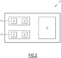
figure 2 est un schéma-bloc de différents éléments d'une partie du système d'alimentation en énergie électrique.
- there
figure 1 is a schematic representation of an installation comprising a wind turbine and an electrical energy supply system, and - there
figure 2 is a block diagram of different elements of part of the electrical power supply system.
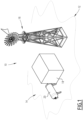
Il est représenté dans la
L'installation 10 est destinée à fournir de l'électricité de manière autonome.The
L'installation 10 est installée dans un endroit éloigné comme une île comme l'indique schématique la frontière 12.
L'installation 10 comporte un système d'alimentation en énergie électrique 14 et une éolienne 16.The
Une éolienne 16 est un dispositif qui transforme l'énergie cinétique du vent en énergie mécanique, dite énergie éolienne, laquelle est ensuite le plus souvent transformée en énergie électrique. Pour une telle transformation, l'éolienne 16 comporte deux génératrices, à savoir une génératrice de petite puissance (pour les vents faibles) et une génératrice de grande puissance (pour les vents élevés), ainsi qu'une partie mécanique incluant notamment des pâles exposées au vent.A
L'éolienne 16 comporte également un contrôleur permettant de contrôler aussi bien la génératrice que la partie mécanique. A titre d'exemple, le contrôleur est capable de gérer l'angle entre le vent et les pâles (parfois appelé selon la dénomination anglaise correspondante de « pitch ») pour que cet angle ne dépasse pas une valeur prédéfinie.The
Bien qu'une seule éolienne 16 est représentée sur la
L'éolienne 16 est alimentée par le système d'alimentation en énergie électrique 14 qui est désigné système 14 dans la suite.The
Le système 14 comporte une structure 18 et un réservoir à hydrogène 20.The
La structure 18 est posée ou fixée au sol et comprend des parois latérales et un toit définissant un espace intérieur.The
Dans cet espace intérieur, différents éléments du système 14 sont présents parmi lesquels ceux représentés sur la
En référence à cette figure, le système 14 comporte un bloc pile à combustible 24, un dispositif de stockage d'énergie batterie 26 et une unité de contrôle 28.Referring to this figure, the
Le bloc pile à combustible 24 comporte une pile à combustible 30 et un onduleur 32.The
Une pile à combustible 30 est un générateur dans lequel la fabrication de l'électricité se fait grâce à l'oxydation sur une électrode d'un combustible réducteur couplée à la réduction sur l'autre électrode d'un oxydant.A
Autrement formulé, la pile à combustible 30 est une unité génératrice électrochimique à combustible gazeux.In other words, the
Selon l'exemple décrit, le combustible est du dihydrogène et l'oxydant est le dioxygène. Le dihydrogène utilisé comme combustible est stocké dans le réservoir 40.According to the example described, the fuel is dihydrogen and the oxidant is dioxygen. The dihydrogen used as fuel is stored in tank 40.
Plus précisément, la pile à combustible est une pile utilisant la technologie à membrane d'échange de protons (plus souvent désignée sous l'abréviation PEM renvoyant à la dénomination anglaise de « Proton Exchange Membrane »).More precisely, the fuel cell is a cell using proton exchange membrane technology (more often referred to by the abbreviation PEM referring to the English name of “Proton Exchange Membrane”).
L'onduleur 32 permet d'ajuster la tension générée par la pile à combustible 30.The
Dans la suite, l'onduleur 32 est appelé « premier onduleur 32 ».In the following, the
Le dispositif de stockage d'énergie batterie 26 est parfois dénommé BESS en référence à l'abréviation de dénomination anglaise de « Battery Energy Storage System ».The battery
Selon l'exemple décrit, le dispositif de stockage d'énergie batterie 26 comporte plusieurs batteries 34 et un onduleur 36.According to the example described, the battery
L'onduleur 36 est appelé « deuxième onduleur 36 » dans la suite de la description pour ne pas le confondre avec le premier onduleur 32.The
Les batteries 34 permettent de stocker l'énergie de la pile à combustible 30 qui n'est pas consommée par l'ensemble des charges et de la relâcher lorsque l'énergie de la pile à combustible 30 devient insuffisante.The
Les batteries 34 sont, par exemple, des batteries de type lithium-ion pour garantir une bonne longévité du système 14.The
Le deuxième onduleur 36 sert à convertir une tension continue en une tension alternative.The
Le deuxième onduleur 36 alimente en puissance réactive l'éolienne 16.The
L'éolienne 16 met en jeu deux formes de puissance, à savoir la puissance active et la puissance réactive.The
La puissance active consommée (généralement exprimée en kWh) se transforme intégralement en puissance mécanique (travail) et en chaleur (pertes) alors que la puissance électrique réactive consommée (généralement exprimée en kVar) sert essentiellement à l'alimentation des circuits magnétiques de l'éolienne 16.The active power consumed (generally expressed in kWh) is transformed entirely into mechanical power (work) and heat (losses) while the reactive electrical power consumed (generally expressed in kVar) is essentially used to supply the magnetic circuits of the
Dans l'exemple décrit, le deuxième onduleur 36 applique une rampe de courant sur l'éolienne 16 lors du démarrage puis applique un courant constant.In the example described, the
L'étude des coupures de courant dans l'installation 10 par la demanderesse ont montré que ces coupures de courant sont liées à une demande en courant que le dispositif de stockage d'énergie batterie 26 ne peut pas fournir.The study of the power cuts in the
Il convient de noter que cela a demandé une vraie analyse de chacune de ces coupures car il n'est pas possible de différencier un vrai court-circuit sur le système 14 d'un problème de demande en courant trop important pour les capacités des éléments du système 14.It should be noted that this required a real analysis of each of these cuts because it is not possible to differentiate a real short circuit on
Ces cas ont lieu lorsque l'éolienne 16 demande un fort apport en puissance réactive. De fait, de forts demandes en puissance réactive peuvent entraîner de fortes variations du plan de tension, voire un effondrement du système 14 complet en cas de dépassement du courant apparent maximal autorisé par le dispositif de stockage d'énergie batterie 26.These cases take place when the
Dans l'exemple décrit, cela est spécifiquement le cas de la magnétisation de la génératrice de l'éolienne 16, c'est-à-dire lors du démarrage de la grande génératrice asynchrone de l'éolienne 16 (via son démarreur statique).In the example described, this is specifically the case of the magnetization of the generator of the
Naturellement, la demanderesse a songé à augmenter la capacité d'apport en puissance réactive du dispositif de stockage d'énergie batterie 26. Une telle augmentation est notamment obtenue aisément en ajoutant des batteries 34.Naturally, the applicant thought of increasing the reactive power supply capacity of the battery
Toutefois, outre de surdimensionnement prévisible, des tests de la demanderesse ont montré que le problème perdure du fait que l'éolienne 16 dépend également de conditions extérieures et notamment de la vitesse du vent et de la présence ou non de turbulences dans le flux d'air incident.However, in addition to predictable oversizing, tests by the applicant have shown that the problem persists because the
Là encore, il conviendrait d'augmenter encore la capacité d'apport en puissance réactive du dispositif de stockage d'énergie batterie 26.Here again, it would be appropriate to further increase the reactive power input capacity of the battery
Il est ainsi parvenu à une taille de dispositif de stockage d'énergie batterie 26 peu raisonnable pour ce type d'application.He has thus arrived at a size of battery
Aussi, pour remédier à ces problèmes, le présent système 10 comporte l'unité de contrôle 28 qui est propre à entraîner le démarrage de l'éolienne 16 en apportant de la puissance réactive additionnelle à la machine électrique 16 à l'aide du premier onduleur 32, c'est-à-dire l'onduleur de la pile à combustible 30.Also, to remedy these problems, the
Un tel apport est, par exemple, obtenu en effectuant un démarrage et un arrêt du premier onduleur 32.Such a contribution is, for example, obtained by starting and stopping the
Pour déterminer l'instant où l'unité de contrôle 28 demande le démarrage du premier onduleur 32, il peut être envisagé que l'unité de contrôle 28 reçoit un ordre de démarrage de l'éolienne 16, le démarrage étant déclenchée à réception de l'ordre de démarrage.To determine the moment when the
En variante ou en complément, l'unité de contrôle 28 détecte un besoin en puissance réactive supérieur à la capacité d'apport en puissance réactive du deuxième onduleur 36, le démarrage étant déclenchée en fonction du besoin détecté.As a variant or in addition, the
Concernant l'instant d'arrêt de l'onduleur 32, l'unité de contrôle 28 peut, par exemple, utiliser un temps prédéfini inférieur à 5 minutes. Un temps de 2 minutes est généralement satisfaisant.Concerning the instant of shutdown of the
Plus généralement, l'unité de contrôle 28 sert à contrôler l'ensemble des éléments du système 14 et est en liaison avec le contrôleur de l'éolienne 16 pour obtenir les informations de fonctionnement de l'éolienne 16 et notamment ses besoins en énergie.More generally, the
Une telle interaction entre le contrôleur de l'éolienne 16 et l'unité de contrôle 28 est maintenant décrite en référence à un exemple. Il est supposé que l'éolienne 16 fonctionne initialement sur sa petite génératrice (génératrice de fonctionnement normal). A un certain moment, l'unité de contrôle 28 identifie qu'il serait intéressant d'avoir plus de puissance et voudrait enclencher la génératrice de grande puissance. L'unité de contrôle 28 envoie alors une commande au premier onduleur 32 pour que celui-ci fournisse une puissance réactive de 100 kVar puis envoie la commande au contrôleur de l'éolienne 16 d'enclencher la génératrice de démarrage. Une fois celle-ci en route, le contrôleur de l'éolienne 16 envoie l'information à l'unité de contrôle 18 qui peut alors donner l'ordre à au premier onduleur 32 d'arrêter de fournir 100 kVar.Such interaction between the
Le système 14 permet ainsi d'utiliser le premier onduleur 32 pour démarrer l'éolienne 16, c'est-à-dire ici magnétiser sa génératrice.The
En pratique, les tests de la demanderesse ont montré que la fourniture de puissance réactive préalablement à la demande élève le plan de tension. Dans les tests effectués, l'éolienne 16 est parvenue à démarrer bien qu'il ait été observé une perte du premier onduleur 32 juste après la demande en puissance réactive.In practice, the applicant's tests have shown that the supply of reactive power prior to the demand raises the voltage plan. In the tests carried out, the
La demanderesse attribue cela à un problème de régulation de tension mais, cette perte momentanée du premier onduleur 32 n'est pas gênante pour l'utilisateur dans la mesure où aucune coupure n'a lieu au niveau du système 14 et que l'éolienne 16 a démarré.The applicant attributes this to a voltage regulation problem, but this momentary loss of the
Le premier onduleur 32 peut ainsi être vu comme un support réactif de soutien pour le système 14 en cas de demande de puissance réactive ponctuelle.The
Cette magnétisation s'ajoute à celle déjà effectuée par l'onduleur 36 des batteries 34.This magnetization is added to that already carried out by the
Comme usuellement le premier onduleur 32 d'une pile à combustible 34 est uniquement utilisé pour les conversions de puissances actives, une telle utilisation du premier onduleur 32 de la pile à combustible 30 permet de diminuer le dimensionnement du dispositif de stockage d'énergie batterie 26, et notamment du deuxième onduleur 36.As usually the
Autrement formulé, lors du démarrage, le deuxième onduleur 36 n'a plus à fournir autant de puissance réactive qu'initialement prévu du fait de l'entraide entre le premier onduleur 32 et le deuxième onduleur 36.In other words, during start-up, the
La diminution du besoin en puissance réactive pouvant être atteinte dans le cas décrit est de l'ordre de 100 kVar.The decrease in reactive power requirement that can be achieved in the case described is of the order of 100 kVar.
Cette diminution rend le système 14 bien adapté pour des usages en zones lointaines privées d'un réseau électrique local.This reduction makes the
Le principe qui vient d'être décrit pour une éolienne 16 est également valable pour tout autre type de machine électrique 16 ayant un besoin fort en puissance réactive au démarrage.The principle which has just been described for a
A titre d'exemple de telle machine électrique, on peut citer un moteur ou un transformateur.By way of example of such an electric machine, mention may be made of a motor or a transformer.
En variante ou en complément, le système 14 comporte, en outre, une alimentation auxiliaire supplémentaire et lors du démarrage, l'alimentation auxiliaire supplémentaire est connecté à la machine électrique 16 pour apporter de la puissance réactive supplémentaire à la machine électrique 16.As a variant or in addition, the
A titre d'exemple, l'alimentation auxiliaire supplémentaire est un onduleur d'une cellule photovoltaïque, un groupe électrogène ou un électrolyseur.By way of example, the additional auxiliary power supply is an inverter of a photovoltaic cell, a generator or an electrolyser.
Claims (10)
l'onduleur (32) de la pile à combustible (30) et la pile à combustible (32) formant un bloc de pile à combustible (24), l'au moins une batterie et l'onduleur (36) de l'au moins une batterie (34) formant un dispositif de stockage d'énergie batterie (26), le bloc de pile à combustible (24) et le dispositif de stockage d'énergie batterie (26) faisant partie d'un même système d'alimentation en énergie électrique (14).
the inverter (32) of the fuel cell (30) and the fuel cell (32) forming a fuel cell block (24), the at least one battery and the inverter (36) of the at least one battery (34) forming a battery energy storage device (26), the fuel cell stack (24) and the battery energy storage device (26) being part of a same power system into electrical energy (14).
Applications Claiming Priority (1)
| Application Number | Priority Date | Filing Date | Title |
|---|---|---|---|
| FR2112386A FR3129545A1 (en) | 2021-11-23 | 2021-11-23 | Method for starting an electric machine and associated devices |
Publications (1)
| Publication Number | Publication Date |
|---|---|
| EP4184784A1 true EP4184784A1 (en) | 2023-05-24 |
Family
ID=80225438
Family Applications (1)
| Application Number | Title | Priority Date | Filing Date |
|---|---|---|---|
| EP22209025.0A Pending EP4184784A1 (en) | 2021-11-23 | 2022-11-23 | Method for starting an electric machine and associated devices |
Country Status (2)
| Country | Link |
|---|---|
| EP (1) | EP4184784A1 (en) |
| FR (1) | FR3129545A1 (en) |
Citations (6)
| Publication number | Priority date | Publication date | Assignee | Title |
|---|---|---|---|---|
| US20050200133A1 (en) * | 2002-03-08 | 2005-09-15 | Aloys Wobben | Separate network and method for operating a separate network |
| EP1928081A2 (en) * | 2006-11-30 | 2008-06-04 | Eaton Power Quality Corporation | Power supply apparatus, methods and computer program products using D-Q domain based synchronization techniques |
| US20100208501A1 (en) * | 2009-02-19 | 2010-08-19 | Stefan Matan | Power transfer management for local power sources of a grid-tied load |
| EP2317623A1 (en) * | 2009-10-30 | 2011-05-04 | General Electric Company | Hybrid wind-solar inverters |
| KR102086352B1 (en) * | 2018-09-14 | 2020-03-09 | 한국전력공사 | Hybrid power system performing power distribution between fuel cell and battery |
| CN108336723B (en) * | 2017-12-08 | 2021-05-04 | 上海电力学院 | Energy management method for fuel cell hybrid power mobile welding robot |
-
2021
- 2021-11-23 FR FR2112386A patent/FR3129545A1/en active Pending
-
2022
- 2022-11-23 EP EP22209025.0A patent/EP4184784A1/en active Pending
Patent Citations (6)
| Publication number | Priority date | Publication date | Assignee | Title |
|---|---|---|---|---|
| US20050200133A1 (en) * | 2002-03-08 | 2005-09-15 | Aloys Wobben | Separate network and method for operating a separate network |
| EP1928081A2 (en) * | 2006-11-30 | 2008-06-04 | Eaton Power Quality Corporation | Power supply apparatus, methods and computer program products using D-Q domain based synchronization techniques |
| US20100208501A1 (en) * | 2009-02-19 | 2010-08-19 | Stefan Matan | Power transfer management for local power sources of a grid-tied load |
| EP2317623A1 (en) * | 2009-10-30 | 2011-05-04 | General Electric Company | Hybrid wind-solar inverters |
| CN108336723B (en) * | 2017-12-08 | 2021-05-04 | 上海电力学院 | Energy management method for fuel cell hybrid power mobile welding robot |
| KR102086352B1 (en) * | 2018-09-14 | 2020-03-09 | 한국전력공사 | Hybrid power system performing power distribution between fuel cell and battery |
Also Published As
| Publication number | Publication date |
|---|---|
| FR3129545A1 (en) | 2023-05-26 |
Similar Documents
| Publication | Publication Date | Title |
|---|---|---|
| EP2004485B1 (en) | Device and method for generating a back-up electricity supply on board an aircraft | |
| EP3185386B1 (en) | Method for controlling a micro-network for electricity distribution | |
| EP2686934B1 (en) | Self-contained hybrid power supply system for an electrical apparatus, and unit and method for managing the system | |
| EP2004489B1 (en) | Device and method for standby power supply on board an aircraft | |
| WO2017025664A1 (en) | Auxiliary system for storage and supply of electrical energy for multiple uses incorporated in an electricity production plant | |
| WO2006067350A1 (en) | Method and system for stand-alone electrical supply by means of renewable energy | |
| FR3060653A1 (en) | GENERATING UNIT OF NON-PROPULSIVE ELECTRIC POWER | |
| FR3065840A1 (en) | ELECTRIC GENERATION AND DISTRIBUTION SYSTEM AND AIRCRAFT | |
| WO2007060328A1 (en) | Control method and device for a decentralised energy production device and installation comprising at least two production devices which are provided with said control device | |
| EP2590256A1 (en) | Method for managing the operation of a hybrid system | |
| EP3465861B1 (en) | Method for electrical supply of an apparatus by an autonomous hybrid station | |
| EP4184784A1 (en) | Method for starting an electric machine and associated devices | |
| FR2964265A1 (en) | METHOD FOR CHARGING AN ELECTRIC BATTERY | |
| WO2012131235A2 (en) | Method and system for redundantly supplying electrical power to a hybrid motor vehicle | |
| EP2772983B1 (en) | Energy storage device and related management method | |
| EP4141256A1 (en) | Operation of a disconnected wind turbine | |
| WO2012001281A1 (en) | Station for replacing motor vehicle electric batteries | |
| FR3137805A1 (en) | Electricity supply device adapted to maintain the inertia of an electrical system | |
| FR3129541A1 (en) | Electricity supply device of the power electronics device type adapted to contribute to the inertia of an electrical system | |
| EP4264769A1 (en) | An improved energy management system and microgrid | |
| CN116940758A (en) | Wind turbine and method | |
| JP2023037567A (en) | Power storage/discharge system | |
| JP2023549773A (en) | How to stabilize island mode in energy hubs | |
| FR3112039A1 (en) | Power transfer system between an AC network and a reversible hydraulic turbine | |
| FR2997056A1 (en) | Method for controlling autonomy of extension cable of car, involves carrying out unballasting process when generated power is not completely consumed, and controlling autonomy of cable such that auxiliary power is below minimal power |
Legal Events
| Date | Code | Title | Description |
|---|---|---|---|
| PUAI | Public reference made under article 153(3) epc to a published international application that has entered the european phase |
Free format text: ORIGINAL CODE: 0009012 |
|
| STAA | Information on the status of an ep patent application or granted ep patent |
Free format text: STATUS: THE APPLICATION HAS BEEN PUBLISHED |
|
| AK | Designated contracting states |
Kind code of ref document: A1 Designated state(s): AL AT BE BG CH CY CZ DE DK EE ES FI FR GB GR HR HU IE IS IT LI LT LU LV MC ME MK MT NL NO PL PT RO RS SE SI SK SM TR |
|
| STAA | Information on the status of an ep patent application or granted ep patent |
Free format text: STATUS: REQUEST FOR EXAMINATION WAS MADE |
|
| 17P | Request for examination filed |
Effective date: 20231107 |
|
| RBV | Designated contracting states (corrected) |
Designated state(s): AL AT BE BG CH CY CZ DE DK EE ES FI FR GB GR HR HU IE IS IT LI LT LU LV MC ME MK MT NL NO PL PT RO RS SE SI SK SM TR |
|
| RAP1 | Party data changed (applicant data changed or rights of an application transferred) |
Owner name: POWIDIAN ENERGY |