EP4184758A1 - Elektromotor eines luftfahrzeugs - Google Patents
Elektromotor eines luftfahrzeugs Download PDFInfo
- Publication number
- EP4184758A1 EP4184758A1 EP22193785.7A EP22193785A EP4184758A1 EP 4184758 A1 EP4184758 A1 EP 4184758A1 EP 22193785 A EP22193785 A EP 22193785A EP 4184758 A1 EP4184758 A1 EP 4184758A1
- Authority
- EP
- European Patent Office
- Prior art keywords
- heat
- electric motor
- aircraft electric
- stator
- working fluid
- Prior art date
- Legal status (The legal status is an assumption and is not a legal conclusion. Google has not performed a legal analysis and makes no representation as to the accuracy of the status listed.)
- Pending
Links
- 238000001816 cooling Methods 0.000 claims abstract description 78
- 238000004804 winding Methods 0.000 claims abstract description 67
- 239000012530 fluid Substances 0.000 claims abstract description 56
- 239000003507 refrigerant Substances 0.000 claims description 10
- 239000006185 dispersion Substances 0.000 claims description 7
- 229920006395 saturated elastomer Polymers 0.000 claims description 3
- LYCAIKOWRPUZTN-UHFFFAOYSA-N Ethylene glycol Chemical compound OCCO LYCAIKOWRPUZTN-UHFFFAOYSA-N 0.000 description 3
- DNIAPMSPPWPWGF-UHFFFAOYSA-N Propylene glycol Chemical compound CC(O)CO DNIAPMSPPWPWGF-UHFFFAOYSA-N 0.000 description 3
- 238000003475 lamination Methods 0.000 description 3
- 239000000463 material Substances 0.000 description 3
- 238000012546 transfer Methods 0.000 description 3
- CSCPPACGZOOCGX-UHFFFAOYSA-N Acetone Chemical compound CC(C)=O CSCPPACGZOOCGX-UHFFFAOYSA-N 0.000 description 2
- LFQSCWFLJHTTHZ-UHFFFAOYSA-N Ethanol Chemical compound CCO LFQSCWFLJHTTHZ-UHFFFAOYSA-N 0.000 description 2
- 229910000831 Steel Inorganic materials 0.000 description 2
- 239000002826 coolant Substances 0.000 description 2
- 239000012809 cooling fluid Substances 0.000 description 2
- 238000013461 design Methods 0.000 description 2
- 238000005516 engineering process Methods 0.000 description 2
- 230000004907 flux Effects 0.000 description 2
- 230000000116 mitigating effect Effects 0.000 description 2
- 239000010959 steel Substances 0.000 description 2
- XLYOFNOQVPJJNP-UHFFFAOYSA-N water Substances O XLYOFNOQVPJJNP-UHFFFAOYSA-N 0.000 description 2
- OKIYQFLILPKULA-UHFFFAOYSA-N 1,1,1,2,2,3,3,4,4-nonafluoro-4-methoxybutane Chemical compound COC(F)(F)C(F)(F)C(F)(F)C(F)(F)F OKIYQFLILPKULA-UHFFFAOYSA-N 0.000 description 1
- 229910000576 Laminated steel Inorganic materials 0.000 description 1
- 239000003570 air Substances 0.000 description 1
- 238000013459 approach Methods 0.000 description 1
- 230000000712 assembly Effects 0.000 description 1
- 238000000429 assembly Methods 0.000 description 1
- 239000003990 capacitor Substances 0.000 description 1
- 229910017052 cobalt Inorganic materials 0.000 description 1
- 239000010941 cobalt Substances 0.000 description 1
- GUTLYIVDDKVIGB-UHFFFAOYSA-N cobalt atom Chemical compound [Co] GUTLYIVDDKVIGB-UHFFFAOYSA-N 0.000 description 1
- 239000002131 composite material Substances 0.000 description 1
- 150000001875 compounds Chemical class 0.000 description 1
- 238000009826 distribution Methods 0.000 description 1
- 230000005672 electromagnetic field Effects 0.000 description 1
- 229940093476 ethylene glycol Drugs 0.000 description 1
- 239000000945 filler Substances 0.000 description 1
- 230000017525 heat dissipation Effects 0.000 description 1
- 230000020169 heat generation Effects 0.000 description 1
- 238000009413 insulation Methods 0.000 description 1
- 239000003562 lightweight material Substances 0.000 description 1
- 239000007788 liquid Substances 0.000 description 1
- 238000004519 manufacturing process Methods 0.000 description 1
- 238000005259 measurement Methods 0.000 description 1
- 230000007246 mechanism Effects 0.000 description 1
- 238000000034 method Methods 0.000 description 1
- 239000000203 mixture Substances 0.000 description 1
- 238000012986 modification Methods 0.000 description 1
- 230000004048 modification Effects 0.000 description 1
- 230000010355 oscillation Effects 0.000 description 1
- 230000008569 process Effects 0.000 description 1
- 229960004063 propylene glycol Drugs 0.000 description 1
- 235000013772 propylene glycol Nutrition 0.000 description 1
- 238000005086 pumping Methods 0.000 description 1
- 238000004513 sizing Methods 0.000 description 1
- 208000016261 weight loss Diseases 0.000 description 1
Images


Classifications
-
- H—ELECTRICITY
- H02—GENERATION; CONVERSION OR DISTRIBUTION OF ELECTRIC POWER
- H02K—DYNAMO-ELECTRIC MACHINES
- H02K9/00—Arrangements for cooling or ventilating
- H02K9/22—Arrangements for cooling or ventilating by solid heat conducting material embedded in, or arranged in contact with, the stator or rotor, e.g. heat bridges
- H02K9/225—Heat pipes
-
- B—PERFORMING OPERATIONS; TRANSPORTING
- B64—AIRCRAFT; AVIATION; COSMONAUTICS
- B64D—EQUIPMENT FOR FITTING IN OR TO AIRCRAFT; FLIGHT SUITS; PARACHUTES; ARRANGEMENT OR MOUNTING OF POWER PLANTS OR PROPULSION TRANSMISSIONS IN AIRCRAFT
- B64D27/00—Arrangement or mounting of power plants in aircraft; Aircraft characterised by the type or position of power plants
- B64D27/02—Aircraft characterised by the type or position of power plants
- B64D27/24—Aircraft characterised by the type or position of power plants using steam or spring force
-
- B—PERFORMING OPERATIONS; TRANSPORTING
- B64—AIRCRAFT; AVIATION; COSMONAUTICS
- B64D—EQUIPMENT FOR FITTING IN OR TO AIRCRAFT; FLIGHT SUITS; PARACHUTES; ARRANGEMENT OR MOUNTING OF POWER PLANTS OR PROPULSION TRANSMISSIONS IN AIRCRAFT
- B64D33/00—Arrangements in aircraft of power plant parts or auxiliaries not otherwise provided for
- B64D33/08—Arrangements in aircraft of power plant parts or auxiliaries not otherwise provided for of power plant cooling systems
-
- H—ELECTRICITY
- H02—GENERATION; CONVERSION OR DISTRIBUTION OF ELECTRIC POWER
- H02K—DYNAMO-ELECTRIC MACHINES
- H02K11/00—Structural association of dynamo-electric machines with electric components or with devices for shielding, monitoring or protection
- H02K11/30—Structural association with control circuits or drive circuits
- H02K11/33—Drive circuits, e.g. power electronics
-
- H—ELECTRICITY
- H02—GENERATION; CONVERSION OR DISTRIBUTION OF ELECTRIC POWER
- H02K—DYNAMO-ELECTRIC MACHINES
- H02K21/00—Synchronous motors having permanent magnets; Synchronous generators having permanent magnets
- H02K21/12—Synchronous motors having permanent magnets; Synchronous generators having permanent magnets with stationary armatures and rotating magnets
- H02K21/22—Synchronous motors having permanent magnets; Synchronous generators having permanent magnets with stationary armatures and rotating magnets with magnets rotating around the armatures, e.g. flywheel magnetos
-
- H—ELECTRICITY
- H02—GENERATION; CONVERSION OR DISTRIBUTION OF ELECTRIC POWER
- H02K—DYNAMO-ELECTRIC MACHINES
- H02K5/00—Casings; Enclosures; Supports
- H02K5/04—Casings or enclosures characterised by the shape, form or construction thereof
- H02K5/20—Casings or enclosures characterised by the shape, form or construction thereof with channels or ducts for flow of cooling medium
- H02K5/203—Casings or enclosures characterised by the shape, form or construction thereof with channels or ducts for flow of cooling medium specially adapted for liquids, e.g. cooling jackets
-
- H—ELECTRICITY
- H02—GENERATION; CONVERSION OR DISTRIBUTION OF ELECTRIC POWER
- H02K—DYNAMO-ELECTRIC MACHINES
- H02K9/00—Arrangements for cooling or ventilating
- H02K9/19—Arrangements for cooling or ventilating for machines with closed casing and closed-circuit cooling using a liquid cooling medium, e.g. oil
- H02K9/20—Arrangements for cooling or ventilating for machines with closed casing and closed-circuit cooling using a liquid cooling medium, e.g. oil wherein the cooling medium vaporises within the machine casing
-
- H—ELECTRICITY
- H02—GENERATION; CONVERSION OR DISTRIBUTION OF ELECTRIC POWER
- H02K—DYNAMO-ELECTRIC MACHINES
- H02K1/00—Details of the magnetic circuit
- H02K1/06—Details of the magnetic circuit characterised by the shape, form or construction
- H02K1/22—Rotating parts of the magnetic circuit
- H02K1/27—Rotor cores with permanent magnets
- H02K1/2786—Outer rotors
-
- H—ELECTRICITY
- H02—GENERATION; CONVERSION OR DISTRIBUTION OF ELECTRIC POWER
- H02K—DYNAMO-ELECTRIC MACHINES
- H02K3/00—Details of windings
- H02K3/04—Windings characterised by the conductor shape, form or construction, e.g. with bar conductors
- H02K3/24—Windings characterised by the conductor shape, form or construction, e.g. with bar conductors with channels or ducts for cooling medium between the conductors
Definitions
- the present disclosure relates to electric motors, and more particularly, to electric motor assemblies with high efficiency and power density with a light weight for aircraft applications.
- Traditional electric motors may include a stator and a rotor, with electrical motor windings in the stator that, when energized, drive rotation of the rotor about a central axis. Heat is generated in the motor windings, which are located in slots in the stator. The windings are separated from the exterior of the motor by layers of insulation and laminated steel, which makes up the stator. These contributors to internal thermal resistance limit the allowable heat generation and thus the allowable electrical current in the windings.
- the energy density of an electric motor is typically limited by heat dissipation from the motor windings of the stator. The requirement to be met is a maximum hot spot temperature in the motor windings that is not to be exceeded.
- Conventional motor thermal management includes natural convection from large fins on the outside of a motor jacket, or liquid cooling in the motor jacket. Both of these solutions undesirably add volume and/or weight to the motor, due to the addition of, at least, the jacket.
- aircraft electric motors include a motor unit having a rotor and a stator, wherein the stator includes a plurality of windings and cooling channels arranged to provide cooling to the plurality of windings, a drive unit configured to drive operation of the motor unit, and a cooling system.
- the cooling system includes an oscillating heat pipe containing a first working fluid, wherein the oscillating heat pipe is arranged to pick up heat from at least one winding, the oscillating heat pipe having an evaporator section arranged in thermal contact with the at least one winding and a condenser section arranged away from the evaporator section and a heat pickup portion arranged to receive a second working fluid to remove heat from the condenser section of the oscillating heat pipe.
- further embodiments of the aircraft electric motors may include a cold plate, wherein the heat pickup portion is part of the cold plate.
- further embodiments of the aircraft electric motors may include that the cold plate comprises one or more heat dispersion elements arranged to thermally interact with the second working fluid.
- further embodiments of the aircraft electric motors may include that the heat dispersion elements comprise at least one of fins and pedestals.
- further embodiments of the aircraft electric motors may include that the heat pick up portion comprises at least one cooling channel formed within the cold plate and configured to receive the second working fluid.
- further embodiments of the aircraft electric motors may include a pump configured to pump the second working fluid through the at least one cooling channel formed within the cold plate.
- further embodiments of the aircraft electric motors may include a heat exchanger fluidly coupled to the at least one cooling channel formed within the cold plate, the heat exchanger configured to receive the second working fluid to remove heat therefrom.
- further embodiments of the aircraft electric motors may include that the cold plate is configured to structurally support at least a portion of the stator.
- further embodiments of the aircraft electric motors may include that the oscillating heat pipe is integrally formed with the cold plate as a unitary structure.
- further embodiments of the aircraft electric motors may include that the oscillating heat pipe is embedded within the at least one winding.
- further embodiments of the aircraft electric motors may include that the oscillating heat pipe is arranged as an in-slot structure arranged adjacent to and in thermal contact with the at least one winding.
- further embodiments of the aircraft electric motors may include a motor housing arranged about the stator, wherein the heat pickup portion is part of the motor housing.
- further embodiments of the aircraft electric motors may include that the evaporator section of the oscillating heat pipe is arranged within the stator and the condenser section is arranged within the motor housing.
- further embodiments of the aircraft electric motors may include that the windings are arranged in a U-shape configuration.
- further embodiments of the aircraft electric motors may include that the motor unit comprises rotor having U-shaped magnets arranged about the windings of the stator.
- cooling system further includes a header and a heat exchanger configured to supply the second working fluid to the heat pickup portion.
- further embodiments of the aircraft electric motors may include that the rotor and stator are arranged in an annular configuration.
- further embodiments of the aircraft electric motors may include that the first working fluid is a saturated refrigerant
- further embodiments of the aircraft electric motors may include that the first working fluid is a dielectric refrigerant.
- further embodiments of the aircraft electric motors may include that the dielectric refrigerant is a hydrofluorocarbon (HFC), a hydrofluro-olefin (HFO), or a hydrofluoroether (HFE).
- HFC hydrofluorocarbon
- HFO hydrofluro-olefin
- HFE hydrofluoroether
- aircraft electric motors include a motor unit having a rotor and a stator, wherein the stator includes a plurality of windings and cooling channels arranged to provide cooling to the plurality of windings, a means for driving operation of the motor unit, and a cooling system.
- the cooling system includes an oscillating heat pipe containing a first working fluid, wherein the oscillating heat pipe is arranged to pick up heat from at least one winding, the oscillating heat pipe having an evaporator section arranged in thermal contact with the at least one winding and a condenser section arranged away from the evaporator section and a means for heat pickup arranged to receive a second working fluid to remove heat from the condenser section of the oscillating heat pipe.
- further embodiments of the aircraft electric motors may include that the means for driving operation of the motor unit comprises at least one power module system, and the means for heat pickup comprises a cold plate.
- FIGS. 1A-1B schematic illustrations of an electric motor 100 that may incorporate embodiments of the present disclosure are shown.
- FIG. 1A illustrates a cross-sectional view of the electric motor 100
- FIG. 1B illustrates a cross-sectional view of a stator core of the electric motor 100.
- the electric motor 100 includes a rotor 102 configured to rotate about a rotation axis 104.
- a stator 106 is located radially outboard of the rotor 102 relative to the rotation axis 104, with a radial air gap 108 located between the rotor 102 and the stator 106.
- the rotor 102 may be mounted on a shaft 110 which may impart rotational movement to the rotor 102 or may be driven by rotation of the rotor 102, as will be appreciated by those of skill in the art.
- the rotor 102 and the shaft 110 may be fixed together such that the rotor 102 and the shaft 110 rotate about the rotation axis 104 together as one piece.
- the stator 106 includes a stator core 112 in which a plurality of electrically conductive stator windings 114 are disposed.
- the stator core 112 is formed from a plurality of axially stacked laminations 116, which are stacked along the rotation axis 104.
- the laminations 116 are formed from a steel material, but one skilled in the art will readily appreciate that other materials may be utilized.
- the stator windings 114 include core segments 118 extending through the stator core 112 and end turn segments 120 extending from each axial stator end 122 of the stator core 112 and connecting circumferentially adjacent core segments 118.
- FIG. 1A illustrates the stator core 112 arranged radially inward from the stator windings 114, it will be appreciated that other configurations are possible without departing from the scope of the present disclosure.
- the stator structure may be arranged radially inward from a rotating rotor structure.
- FIG. 1B is an axial cross-sectional view of the stator core 112.
- Each lamination 116 of the stator core 112 includes a radially outer rim 124 with a plurality of stator teeth 126 extending radially inwardly from the outer rim 124 toward the rotation axis 104.
- Each of the stator teeth 126 terminate at a tooth tip 128, which, together with a rotor outer surface 130 (shown in FIG. 1A ) of the rotor 102, may define the radial air gap 108.
- Circumferentially adjacent stator teeth 126 define an axially-extending tooth gap 132 therebetween.
- a plurality of stator fins 134 extend radially outwardly from the outer rim 124.
- Electric motors may require cooling due to high density configurations, various operational parameters, or for other reasons.
- high-power-density aviation-class electric motors and drives may require advanced cooling technologies to ensure proper operation of the motors/drives.
- These machines are generally thermally limited at high power ratings and their performance can be improved by mitigating thermal limitations.
- a thermal management system TMS is integrated into the system, which provides cooling to components of the system.
- TMS thermal management system
- aviation electric motors are provided herein.
- the aviation electric motors or aircraft electric motors, described herein, incorporate lightweight materials and compact design to reduce weight, improve thermal efficiencies, improve power efficiencies, and improve power density.
- FIGS. 2A-2D schematic illustrations of an aircraft electric motor 200 in accordance with an embodiment of the present disclosure are shown.
- FIG. 2A is an isometric illustration of the aircraft electric motor 200
- FIG. 2B is a side elevation view of the aircraft electric motor 200
- FIG. 2C is a partial cut-away view illustrating internal components of the aircraft electric motor 200
- FIG. 2D is a schematic illustration of components of the aircraft electric motor 200 as separated from each other.
- the aircraft electric motor 200 includes a motor housing 202, a cooling system 204, a first power module system 206, and a second power module system 208.
- the motor housing 202 houses a stator 210 and a rotor 212, with the rotor 212 configured to be rotatable about the stator 210.
- the rotor 212 includes a U-shaped magnet 214 arranged within a similarly shaped U-shaped rotor sleeve 216.
- the rotor sleeve 216 is operably connected to a hub 218.
- the hub 218 is fixedly attached to a first shaft 220.
- the first shaft 220 is operably connected to a second shaft 222.
- the first shaft 220 may be a high speed shaft and may be referred to as an input shaft.
- the second shaft 222 may be a low speed shaft and may be referred to as an output shaft.
- the connection between the first shaft 220 and the second shaft 222 may be by a gear assembly 224, as described herein.
- the cooling system 204 is configured to provide cooling to the components of the aircraft electric motor 200.
- the cooling system 204 includes a heat exchanger 226 and a header 228.
- the heat exchanger 226 and the header 228 may form a closed-loop cooling system that may provide air-cooling to a working fluid at the heat exchanger 226.
- the header 228 may be, in some configurations, a two-phase di-electric cooling header.
- a cooled working fluid may be pumped from the heat exchanger 226 into the header 228 using a pump 229 and distributed into embedded cooling channels 230 that are arranged within the stator 210.
- heat is generated and picked up by the working fluid within the embedded cooling channels 230.
- This heated working fluid is then passed through the header 228 back to the heat exchanger 226 to be cooled, such as by air cooling.
- air-cooling other cooling processes may be employed without departing from the scope of the present disclosure.
- the heat exchanger 226 of the cooling system 204 may be a circular structure that is arranged about the motor housing 202. This configuration and arrangement allows for improved compactness of the system, which may be advantageous for aircraft applications.
- the rotor sleeve 216 with the magnets 214, the stator 210, and the gear assembly 224 fit together (although moveable relative to each other) within the motor housing 202, providing for a compact (low volume/size) design.
- the rotor sleeve 216 may be operably coupled to a first shaft 220 by the hub 218.
- the first shaft 220 may be operably coupled to a first gear element 232 and the second shaft 222 may be operably coupled to a second gear element 234.
- the first and second gear elements 232, 234 may form the gear assembly 224.
- the first and second gear elements 232, 234 are arranged to transfer rotational movement from the first shaft 220, which is driven in rotation by the hub 218 and the rotor sleeve 216 of the rotor 212, to the second shaft 222.
- the first shaft 220 may be operably connected to a sun gear as the first gear element 232 that engages with a plurality of planetary gears and drives rotation of the second gear element 234 which may be operably connected to the second shaft 222.
- the second shaft 222 may be connected to a fan or other component to be rotated by the aircraft electric motor 200.
- the aircraft electric motor 200 includes the first power module system 206 and the second power module system 208, which may form, in part, a drive unit of the aircraft electric motor 200.
- the first and second power module systems 206, 208 can include capacitors and other electronics, including, but not limited to, printed circuit boards (PCBs) that may enable control and operation of the aircraft electric motor 200.
- PCBs printed circuit boards
- the profile of the aircraft electric motor 200 of the present disclosure presents a low profile or compact arrangement that reduces the volume of the entire power system, which in turn can provide for improved weight reductions.
- the first and second power module systems 206, 208 may be electrically connected to the stator 210 to cause an electric current therein. As the electric current will induce an electromagnetic field which will cause the rotor 212 to rotate.
- FIGS. 3A-3B schematic illustrations of a portion of an aircraft electric motor 300 in accordance with an embodiment of the present disclosure is shown.
- FIGS. 3A-3B illustrate a portion of a rotor 302 and a stator 304 of the aircraft electric motor 300.
- FIG. 3A illustrates the rotor 302 and the stator 304 and
- FIG. 3B illustrates these components arranged within a rotor sleeve 306.
- the rotor 302 is formed of a plurality of U-shaped magnets 308.
- the plurality of magnets 308 can be arranged with alternating polarity in a circular or annular structure.
- Arranged within the "U" of the U-shaped magnets 308 is the stator 304.
- the stator 304 is formed of a plurality of windings 310.
- the windings 310 are arranged with a header 312.
- the header 312 may be part of a cooling system, such as that shown and described above.
- the header 312 can be configured to cycle a working fluid through cooling channels 314 for cooling of the windings 310, as shown in FIG. 3B . As shown in FIG.
- the cooling channels 314 may include a flow restrictor 315 arranged at an inlet side (or an outlet side) of the cooling channel 314.
- the flow restrictor 315 may be used to throttle the flow of a cooling fluid to provide efficient cooling within the cooling channels 314.
- the cooling fluid may be a saturated refrigerant (e.g., dielectric refrigerants including, but not limited to, hydrofluorocarbons (HFC), hydrofluro-olefins (HFO), and/or hydrofluoroethers (HFE)).
- HFC hydrofluorocarbons
- HFO hydrofluro-olefins
- HFE hydrofluoroethers
- the windings 310 may be wrapped about a support structure 316.
- the support structure 316 in some embodiments and as shown in FIG. 3B , may include a laminate portion 318 and a magnetic portion 320.
- the laminate portion 318 may be formed from cobalt steel laminate and the magnetic portion 320 may be formed from a soft magnetic composite.
- the laminate portion 318 may be provided to capture in-plane flux from outer and inner rotor.
- the magnetic portion 320 may be provided to capture end rotor flux and may take a shape/filler in a gap through the end turns of the coil.
- the windings 310 include end connections 322 and may be electrically connected to one or more power module systems of the aircraft electric motor, such as shown above.
- the magnets 306 are U-shaped and arranged within the rotor sleeve 306.
- the rotor sleeve 306 is a substantially U-shaped sleeve that is sized and shaped to receive the U-shaped magnets 308.
- the rotor sleeve 306 can include an inner sleeve 324.
- the inner sleeve 324 may be configured to provide support to a portion of the magnets 308. It will be appreciated that there is no direct contact between the windings 310 and the magnets 308. This lack of contact enables free rotation of the rotor 302 relative to the stator 304 during operation.
- High-power-density aviation-class electric motor and drives may require advanced cooling technologies. These machines are generally thermally limited at high power ratings and their performance can be improved by mitigating thermal limitations. In-slot cooling is an approach to directly cool the motor windings in the slot, leading to lower temperatures, and ultimately higher power density motors. However, manufacturing complexity arises when connecting many small parallel flow channels on one face of the motor.
- in-slot cooling is achieved with oscillating heat pipes (OHPs) having an integrated cold plate to provide local cooling to the motor windings with less complexity than individual flow channels.
- OHPs oscillating heat pipes
- a main fluid loop may have less pressure drop as compared to a configuration with fluid routed directly into slot channels. This has a system-level impact in that a pump and/or rejecting heat exchanger can be smaller and/or lighter in weight as compared to prior systems.
- the OHPs are located in the motor slots, while an integrated cold plate is located externally to the motor slots.
- the cold plate may be positioned at the axial face of the motor.
- the OHP evaporator section of OHP
- the cold plate is integrated with a fluid loop to cool the condenser side of the OHP.
- the cold plate section may take the form of a finned heat sink to be cooled with air.
- Such a system may be passively cooled.
- passive cooling may employ air movement that is already present in a local environment.
- no power input is required to the system for the purpose of cooling and there may be few or no moving parts.
- a fan may be used to propel air over a heat sink, therefore introducing power input and moving parts.
- FIG. 4 a schematic illustration of a portion of an aircraft electric motor 400 in accordance with an embodiment of the present disclosure is shown.
- the aircraft electric motor 400 may be similar to that shown and described above, with components omitted for clarity and brevity of discussion.
- the aircraft electric motor 400 includes a stator 402 illustrating a single winding 403 (e.g., one winding 310 as shown in FIGS. 3A-3B ).
- FIG. 4 is merely illustrative, and the stator 402 may include numerous windings arranged in an annular or circular structure, as shown and described above.
- the stator 402 may be arranged relative to a rotor and configured to induce rotation of the rotor, as described above.
- each winding may be configured with one or more in-slot oscillating heat pipes 406 (in-slot OHP 406).
- Oscillating heat pipes use pressure-driven, two-phase fluid flow to rapidly transfer heat between heat sources and heat sinks.
- the in-slot OHP 406 includes an evaporator section 408 (e.g., evaporator portion or section) and a condenser section 410 (e.g., condenser portion or section) and contains a first working fluid 412 therein.
- the evaporator section 408 of the in-slot OHP 406 extends adjacent to the winding 403 (or between windings 403) and acquires heat from the windings 403 during operation of the aircraft electric motor 400.
- a working fluid e.g., two-phase fluid
- the heat will be transferred through the evaporator section 408 to the condenser section 410 through the oscillations of the first working fluid 412 within the evaporator section 408 of the in-slot OHP 406.
- the condenser section 410 of the in-slot OHP 406 extends into a cold plate 414.
- the heat of the in-slot OHP 406 is rejected from the condenser section 410 into the cold plate 414.
- the cold plate 414 includes the condenser section 410 of the in-slot OHP 406 and a heat pickup portion 416 of a cooling loop 418.
- the heat pickup portion 416 of the cooling loop 418 may be integrated into the cold plate 414.
- the heat pickup portion 416 may be formed of a plurality of channels formed in the cold plate 414 that contain a second working fluid 420.
- the second working fluid may be a coolant or refrigerant, and in some such embodiments may be a single-phase fluid.
- the first working fluid 412 within the OHP 406 may be, for example and without limitation, ethanol, acetone, perfluorinated compounds (PFCs), and/or methoxy-nonafluorobutane, etc.
- the second working fluid 420 may be air, water, ethylene- or propylene-glycol, water mixtures (e.g., EGW, PGW), or a phase-change refrigerant.
- the cooling loop 418 in this embodiment, is an active cooling configuration.
- the second working fluid 420 picks up heat within the cold plate 414 from the condenser section 410 of the OHPs 406.
- a pump 422 is used to provide motive force and drive the second working fluid 420 through the cooling loop 418.
- the second working fluid 420 is pumped, using the pump 422, through a heat exchanger 424 arranged along the cooling loop 418.
- the pump may be downstream of the heat exchanger, and thus the illustrative configuration is not intended to be limiting.
- the heat exchanger 424 may be an air cooled heat exchanger, a fluid cooled heat exchanger, or the like.
- the heat exchanger 424 may be similar to the heat exchanger 226 shown in FIGS. 2A-2D . Heat within the second working fluid 420 is rejected at the heat exchanger 424 and then returned into the cold plate 414 to pick up heat from the condenser section 410 of the OHP 406.
- the in-slot OHPs 406 may be integrally formed with the cold plate 414.
- at least the heat pickup portion 416 of the cooling loop 418 may also be integrally formed within the cold plate 414.
- a single unitary structure may include the OHPs 406, the cold plate 414, and a portion of the cooling loop 418.
- the pump 422 and the heat exchanger 424 may be fluidly coupled to the heat pickup portion 416 of the cooling loop 418 by one or more fluid ports 426 on the cold plate 414.
- the cold plate 414 may include many different condenser sections 410 of different OHPs 406 and a single heat pickup portion 416 of the cooling loop 418.
- the heat pickup portion 416 may be formed of a flow channel or path that interweaves with the condenser sections 410 of the OHPs 406.
- the integrally formed cold plate 414 and OHPs 406 may serve a secondary function of structural support. That is, the OHPs 406 extends into and between the windings 403 and provides support thereto.
- the cold plate 414 may provide structural support to the stator 402.
- the cold plate or heat sink can have different geometric profiles than that illustratively shown.
- the cold plate may have a circle shape to match the shape of the motor.
- the cold plate can include a hole, aperture, or open area in the center to make space for a motor shaft, motor end windings, and/or other motor components or associated components.
- the OHPs may be integrally formed and embedded with the windings. That is, for example, the cooling channels 314 shown in FIG. 3B which are integral and part of the windings 310 may be filled with a two-phase OHP working fluid.
- the end connections 322 may be replaced by the condenser section of the OHPs and the end connections 322 may be part of an integral with a cold plate.
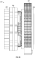
- FIG. 5 a schematic illustration of a portion of an aircraft electric motor 500 in accordance with an embodiment of the present disclosure is shown.
- the aircraft electric motor 500 may be similar to that shown and described above, with components omitted for clarity and brevity of discussion.
- the aircraft electric motor 500 includes a stator 502 illustrating a OHP 504 (e.g., a winding with embedded channels or a separate OHP adjacent windings of the stator 502).
- a stator 502 illustrating a OHP 504 (e.g., a winding with embedded channels or a separate OHP adjacent windings of the stator 502).
- FIG. 5 is merely illustrative, and the stator 502 may include numerous windings arranged in an annular or circular structure, as shown and described above.
- the stator 502 may be arranged relative to a rotor and configured to induce rotation of the rotor, as described above.
- the OHP 504 includes a first working fluid 506 that oscillates within an evaporator section 508 to transfer heat to a condenser section 510 of the OHP 504.
- the condenser section 510 is part of and integral with a cold plate 512.
- the cooling at the cold plate 512 is passive, as compared to the active pumping described with respect to the embodiment of FIG. 4 .
- the condenser section 510 of the OHPs 504 extend into the cold plate 512 which includes a heat pickup portion 514.
- the heat pickup portion 514 of this embodiment, is formed of heat dispersion elements 516.
- the heat dispersion elements 516 may be formed as fins, pedestals, plates, dimples, roughness, or similar structures, textures, surface features, etc. that provide an increased surface area to enable heat pick up by a second working fluid 518.
- the second working fluid 518 may be air that is blown or convey over the heat dispersion elements 516 to remove heat from the heat pickup portion 514.
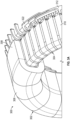
- FIGS. 6A-6B schematic illustrations of a portion of an aircraft electric motor 600 in accordance with an embodiment of the present disclosure is shown.
- the aircraft electric motor 600 may be similar to that shown and described above, with components omitted for clarity and brevity of discussion.
- the aircraft electric motor 600 includes a stator 602 having windings 604 (shown in FIG. 6B ) arranged with OHPs 606 arranged relative thereto.
- the OHPs may be formed as embedded channels within windings of the stator. It will be appreciated that FIGS.
- stator 602 may include numerous windings arranged in an annular or circular structure, as shown and described above.
- the stator 602 may be arranged relative to a rotor and configured to induce rotation of the rotor, as described above.
- the OHPs 606 include an evaporator section 608 and a condenser section 610 with a first working fluid 612 arranged therein.
- the cooling of the first working fluid is provided through a motor housing 614.
- the motor housing 614 in this embodiment, includes heat pickup portions 616 which are arranged relative to slots 618 within the motor housing 614.
- a second working fluid 620 is passed through the slots 618 of the motor housing 614 to provide heat pick up and cool the first working fluid 612.
- the motor housing 614 may operate substantially similar to the cold plates described above and provide structural support to the aircraft electric motor 600 in addition to the cooling properties provided through inclusion of the OHPs 606. In the configuration illustrated in FIGS.
- the cooling at the heat pickup portions 616 is passive and the second working fluid 620 (e.g., air) is passed through the slots 618.
- the slots 618 may be omitted and replaced by an active cooling scheme, such as plates or fins with a refrigerant or coolant that is passed through such structures using a pump and heat exchanger configuration, similar to that shown and described with respect to FIG. 4 .
- the power system 700 includes one or more engines 704, one or more electric motors 706, a power bus electrically connecting the various power sources 704, 706, and a plurality of electrical devices 710 that may be powered by the engines 704 and/or motors 706.
- the power system 700 includes a power distribution system 712 that distributes power 714 through power lines or cables 716.
- the electric motors 706 of the aircraft 702 may be configured similar to the aircraft electric motors shown and described above.
- embodiments of the present disclosure provide for improved electric motors for aircraft and aviation applications.
- the aircraft electric motors of the present disclosure have improved cooling configuration that may improve cooling while eliminating or at least reducing the challenges with cooling windings of aircraft electric motors.
- embodiments of the present disclosure include integrated or integral oscillating heat pipes that provide an efficient mechanism for heat removal from windings of aircraft electric motors.
- the integral OHPs with cold plates or other structures can provide structural support or stability to the aircraft electric motors and/or components thereof.
Landscapes
- Engineering & Computer Science (AREA)
- Power Engineering (AREA)
- Aviation & Aerospace Engineering (AREA)
- Chemical & Material Sciences (AREA)
- Combustion & Propulsion (AREA)
- Mechanical Engineering (AREA)
- Microelectronics & Electronic Packaging (AREA)
- Motor Or Generator Cooling System (AREA)
Applications Claiming Priority (1)
| Application Number | Priority Date | Filing Date | Title |
|---|---|---|---|
| US17/519,766 US11996760B2 (en) | 2021-11-05 | 2021-11-05 | Aircraft electric motor having a stator heat pipe cooling scheme |
Publications (1)
| Publication Number | Publication Date |
|---|---|
| EP4184758A1 true EP4184758A1 (de) | 2023-05-24 |
Family
ID=83191827
Family Applications (1)
| Application Number | Title | Priority Date | Filing Date |
|---|---|---|---|
| EP22193785.7A Pending EP4184758A1 (de) | 2021-11-05 | 2022-09-02 | Elektromotor eines luftfahrzeugs |
Country Status (2)
| Country | Link |
|---|---|
| US (1) | US11996760B2 (de) |
| EP (1) | EP4184758A1 (de) |
Families Citing this family (1)
| Publication number | Priority date | Publication date | Assignee | Title |
|---|---|---|---|---|
| US20230291281A1 (en) * | 2022-03-09 | 2023-09-14 | GM Global Technology Operations LLC | Stator assembly of an electric motor with retrofitted heat pipes |
Citations (4)
| Publication number | Priority date | Publication date | Assignee | Title |
|---|---|---|---|---|
| US20170141654A1 (en) * | 2015-11-13 | 2017-05-18 | General Electric Company | System for thermal management in electrical machines |
| US20170244306A1 (en) * | 2016-02-24 | 2017-08-24 | Ge Aviation Systems Llc | Method and assembly of a power generation system |
| EP3490116A2 (de) * | 2017-11-23 | 2019-05-29 | Baumüller Nürnberg GmbH | Antrieb mit umrichter und kühlmittel |
| JP6622509B2 (ja) * | 2015-08-11 | 2019-12-18 | 株式会社日立製作所 | 電動機冷却装置 |
Family Cites Families (6)
| Publication number | Priority date | Publication date | Assignee | Title |
|---|---|---|---|---|
| US6891306B1 (en) * | 2002-04-30 | 2005-05-10 | Wavecrest Laboratories, Llc. | Rotary electric motor having both radial and axial air gap flux paths between stator and rotor segments |
| US10384913B2 (en) * | 2016-06-13 | 2019-08-20 | Otis Elevatro Company | Thermal management of linear motor |
| US11355252B2 (en) * | 2016-12-30 | 2022-06-07 | Nuscale Power, Llc | Control rod drive mechanism with heat pipe cooling |
| US10272767B1 (en) * | 2018-03-23 | 2019-04-30 | Sf Motors, Inc. | Dual loop liquid cooling of integrated electric drivetrain |
| SG11202112597XA (en) * | 2019-05-16 | 2021-12-30 | Duxion Motors Inc | Electric aircraft propulsion system |
| CN112104167B (zh) | 2020-05-26 | 2022-06-07 | 厦门钨业股份有限公司 | 基于脉动热管的电机 |
-
2021
- 2021-11-05 US US17/519,766 patent/US11996760B2/en active Active
-
2022
- 2022-09-02 EP EP22193785.7A patent/EP4184758A1/de active Pending
Patent Citations (4)
| Publication number | Priority date | Publication date | Assignee | Title |
|---|---|---|---|---|
| JP6622509B2 (ja) * | 2015-08-11 | 2019-12-18 | 株式会社日立製作所 | 電動機冷却装置 |
| US20170141654A1 (en) * | 2015-11-13 | 2017-05-18 | General Electric Company | System for thermal management in electrical machines |
| US20170244306A1 (en) * | 2016-02-24 | 2017-08-24 | Ge Aviation Systems Llc | Method and assembly of a power generation system |
| EP3490116A2 (de) * | 2017-11-23 | 2019-05-29 | Baumüller Nürnberg GmbH | Antrieb mit umrichter und kühlmittel |
Also Published As
| Publication number | Publication date |
|---|---|
| US11996760B2 (en) | 2024-05-28 |
| US20230143600A1 (en) | 2023-05-11 |
Similar Documents
| Publication | Publication Date | Title |
|---|---|---|
| US11271456B2 (en) | Method and assembly of an electric machine | |
| EP4184758A1 (de) | Elektromotor eines luftfahrzeugs | |
| EP4175130A1 (de) | Flugzeugelektromotor mit integriertem kühlsystem | |
| US20220416613A1 (en) | Electric motor with integrated cooling system | |
| EP4262053A1 (de) | Elektromotor eines luftfahrzeugs | |
| WO2021164944A1 (en) | Electric motor with integrated cooling system | |
| US12005771B2 (en) | Lightweight high-efficiency, high temperature electric drive system | |
| EP4096063A1 (de) | Zweiphasenkühlung für elektrische maschinen | |
| US11973376B2 (en) | Electric motor with simplified winding and U-shaped rotor | |
| US20240048030A1 (en) | Electric motor with integrated cooling | |
| US20230082277A1 (en) | Electric motor with integrated cooling system | |
| US11817761B2 (en) | Aircraft electric motor | |
| US11990825B2 (en) | Aircraft electric motor | |
| WO2021164946A1 (en) | Electric motor with integrated cooling system | |
| US11728715B2 (en) | Electric motor with simplified winding and dual rotor | |
| US20240258851A1 (en) | Electric machine having rotor with integrated fan | |
| US20240195233A1 (en) | Magnetic wire infused components for electric machine | |
| US20240204587A1 (en) | Electric machine having multi-function cooling channels | |
| EP4071985A1 (de) | Integrierte motorantriebsarchitektur | |
| US20230361638A1 (en) | Aircraft electric motor | |
| US20240171052A1 (en) | Electric machine having notched magnets | |
| GB2627441A (en) | Winding arrangement for an electrical machine | |
| KR20220148242A (ko) | 가변 토크 생성 전기 기계용 냉각 시스템 |
Legal Events
| Date | Code | Title | Description |
|---|---|---|---|
| PUAI | Public reference made under article 153(3) epc to a published international application that has entered the european phase |
Free format text: ORIGINAL CODE: 0009012 |
|
| STAA | Information on the status of an ep patent application or granted ep patent |
Free format text: STATUS: THE APPLICATION HAS BEEN PUBLISHED |
|
| AK | Designated contracting states |
Kind code of ref document: A1 Designated state(s): AL AT BE BG CH CY CZ DE DK EE ES FI FR GB GR HR HU IE IS IT LI LT LU LV MC MK MT NL NO PL PT RO RS SE SI SK SM TR |
|
| STAA | Information on the status of an ep patent application or granted ep patent |
Free format text: STATUS: REQUEST FOR EXAMINATION WAS MADE |
|
| 17P | Request for examination filed |
Effective date: 20231122 |
|
| RBV | Designated contracting states (corrected) |
Designated state(s): AL AT BE BG CH CY CZ DE DK EE ES FI FR GB GR HR HU IE IS IT LI LT LU LV MC MK MT NL NO PL PT RO RS SE SI SK SM TR |