EP4184565A1 - Apparatus, system, and method for mitigating deformation of spring-loaded heatsinks - Google Patents
Apparatus, system, and method for mitigating deformation of spring-loaded heatsinks Download PDFInfo
- Publication number
- EP4184565A1 EP4184565A1 EP22156148.3A EP22156148A EP4184565A1 EP 4184565 A1 EP4184565 A1 EP 4184565A1 EP 22156148 A EP22156148 A EP 22156148A EP 4184565 A1 EP4184565 A1 EP 4184565A1
- Authority
- EP
- European Patent Office
- Prior art keywords
- heatsink
- heat
- emitting component
- springs
- designated area
- Prior art date
- Legal status (The legal status is an assumption and is not a legal conclusion. Google has not performed a legal analysis and makes no representation as to the accuracy of the status listed.)
- Pending
Links
Images


Classifications
-
- H—ELECTRICITY
- H05—ELECTRIC TECHNIQUES NOT OTHERWISE PROVIDED FOR
- H05K—PRINTED CIRCUITS; CASINGS OR CONSTRUCTIONAL DETAILS OF ELECTRIC APPARATUS; MANUFACTURE OF ASSEMBLAGES OF ELECTRICAL COMPONENTS
- H05K7/00—Constructional details common to different types of electric apparatus
- H05K7/20—Modifications to facilitate cooling, ventilating, or heating
- H05K7/2039—Modifications to facilitate cooling, ventilating, or heating characterised by the heat transfer by conduction from the heat generating element to a dissipating body
-
- H—ELECTRICITY
- H05—ELECTRIC TECHNIQUES NOT OTHERWISE PROVIDED FOR
- H05K—PRINTED CIRCUITS; CASINGS OR CONSTRUCTIONAL DETAILS OF ELECTRIC APPARATUS; MANUFACTURE OF ASSEMBLAGES OF ELECTRICAL COMPONENTS
- H05K7/00—Constructional details common to different types of electric apparatus
- H05K7/20—Modifications to facilitate cooling, ventilating, or heating
- H05K7/2039—Modifications to facilitate cooling, ventilating, or heating characterised by the heat transfer by conduction from the heat generating element to a dissipating body
- H05K7/20436—Inner thermal coupling elements in heat dissipating housings, e.g. protrusions or depressions integrally formed in the housing
- H05K7/2049—Pressing means used to urge contact, e.g. springs
-
- H—ELECTRICITY
- H10—SEMICONDUCTOR DEVICES; ELECTRIC SOLID-STATE DEVICES NOT OTHERWISE PROVIDED FOR
- H10W—GENERIC PACKAGES, INTERCONNECTIONS, CONNECTORS OR OTHER CONSTRUCTIONAL DETAILS OF DEVICES COVERED BY CLASS H10
- H10W40/00—Arrangements for thermal protection or thermal control
- H10W40/60—Securing means for detachable heating or cooling arrangements, e.g. clamps
- H10W40/611—Bolts or screws
-
- G—PHYSICS
- G06—COMPUTING OR CALCULATING; COUNTING
- G06F—ELECTRIC DIGITAL DATA PROCESSING
- G06F1/00—Details not covered by groups G06F3/00 - G06F13/00 and G06F21/00
- G06F1/16—Constructional details or arrangements
- G06F1/20—Cooling means
-
- H—ELECTRICITY
- H05—ELECTRIC TECHNIQUES NOT OTHERWISE PROVIDED FOR
- H05K—PRINTED CIRCUITS; CASINGS OR CONSTRUCTIONAL DETAILS OF ELECTRIC APPARATUS; MANUFACTURE OF ASSEMBLAGES OF ELECTRICAL COMPONENTS
- H05K7/00—Constructional details common to different types of electric apparatus
- H05K7/20—Modifications to facilitate cooling, ventilating, or heating
- H05K7/2039—Modifications to facilitate cooling, ventilating, or heating characterised by the heat transfer by conduction from the heat generating element to a dissipating body
- H05K7/20509—Multiple-component heat spreaders; Multi-component heat-conducting support plates; Multi-component non-closed heat-conducting structures
-
- H—ELECTRICITY
- H10—SEMICONDUCTOR DEVICES; ELECTRIC SOLID-STATE DEVICES NOT OTHERWISE PROVIDED FOR
- H10W—GENERIC PACKAGES, INTERCONNECTIONS, CONNECTORS OR OTHER CONSTRUCTIONAL DETAILS OF DEVICES COVERED BY CLASS H10
- H10W40/00—Arrangements for thermal protection or thermal control
- H10W40/20—Arrangements for cooling
- H10W40/22—Arrangements for cooling characterised by their shape, e.g. having conical or cylindrical projections
-
- H—ELECTRICITY
- H10—SEMICONDUCTOR DEVICES; ELECTRIC SOLID-STATE DEVICES NOT OTHERWISE PROVIDED FOR
- H10W—GENERIC PACKAGES, INTERCONNECTIONS, CONNECTORS OR OTHER CONSTRUCTIONAL DETAILS OF DEVICES COVERED BY CLASS H10
- H10W40/00—Arrangements for thermal protection or thermal control
- H10W40/20—Arrangements for cooling
- H10W40/22—Arrangements for cooling characterised by their shape, e.g. having conical or cylindrical projections
- H10W40/226—Arrangements for cooling characterised by their shape, e.g. having conical or cylindrical projections characterised by projecting parts, e.g. fins to increase surface area
-
- H—ELECTRICITY
- H10—SEMICONDUCTOR DEVICES; ELECTRIC SOLID-STATE DEVICES NOT OTHERWISE PROVIDED FOR
- H10W—GENERIC PACKAGES, INTERCONNECTIONS, CONNECTORS OR OTHER CONSTRUCTIONAL DETAILS OF DEVICES COVERED BY CLASS H10
- H10W40/00—Arrangements for thermal protection or thermal control
- H10W40/20—Arrangements for cooling
- H10W40/231—Arrangements for cooling characterised by their places of attachment or cooling paths
- H10W40/233—Arrangements for cooling characterised by their places of attachment or cooling paths attached to chips
-
- H—ELECTRICITY
- H10—SEMICONDUCTOR DEVICES; ELECTRIC SOLID-STATE DEVICES NOT OTHERWISE PROVIDED FOR
- H10W—GENERIC PACKAGES, INTERCONNECTIONS, CONNECTORS OR OTHER CONSTRUCTIONAL DETAILS OF DEVICES COVERED BY CLASS H10
- H10W40/00—Arrangements for thermal protection or thermal control
- H10W40/60—Securing means for detachable heating or cooling arrangements, e.g. clamps
-
- H—ELECTRICITY
- H10—SEMICONDUCTOR DEVICES; ELECTRIC SOLID-STATE DEVICES NOT OTHERWISE PROVIDED FOR
- H10W—GENERIC PACKAGES, INTERCONNECTIONS, CONNECTORS OR OTHER CONSTRUCTIONAL DETAILS OF DEVICES COVERED BY CLASS H10
- H10W40/00—Arrangements for thermal protection or thermal control
- H10W40/60—Securing means for detachable heating or cooling arrangements, e.g. clamps
- H10W40/625—Clamping parts not primarily conducting heat
Definitions
- Heatsinks are often a critical factor for electronic and mechanical devices.
- a telecommunications device such as a router or switch
- many electronic components may be equipped with heatsinks designed to transfer and/or dissipate heat.
- the heatsinks may include thermally conductive material that transfers heat away from the electronic components, thereby cooling the electronic components and/or enabling them to achieve higher performance.
- Heatsinks may also introduce certain risks into telecommunications devices.
- a high-performing heatsink may be relatively heavy and/or represent a heavy load that is pressed against an electronic component via one or more springs.
- the pressure applied to the heatsink by the springs may actually deform and/or bend the heatsink.
- Such deformation and/or bending of the heatsink may impair, degrade, and/or destroy the heatsink's performance (e.g., crashing a vapor chamber within the heatsink, demating the thermal coupling between the heatsink and the electronic component, and/or cracking the electronic component).
- the pressure applied to the heatsink by the springs may actually deform, crack, and/or other damage the electronic component.
- Such deformation and/or damage of the electronic component may impair, degrade, and/or destroy the electronic component's performance.
- the instant disclosure therefore, identifies and addresses a need for additional and improved apparatuses, systems, and methods for mitigating deformation of spring-loaded heatsinks and/or damaging electronic components cooled by such heatsinks.
- an apparatus for accomplishing such a task may include (1) a heat-emitting component, (2) a heatsink that includes a designated area thermally coupled to the heat-emitting component, (3) a plurality of springs that apply forces that support the thermal coupling between the designated area of the heatsink and the heat-emitting component, and (4) a pressure plate that concentrates the forces applied by the springs toward the designated area of the heatsink.
- a system for accomplishing such a task may include (1) a computing device and (2) a spring-loaded heat exchanger incorporated in the computing device, wherein the spring-loaded heat exchanger comprising (A) a heat-emitting component, (B) a heatsink that includes a designated area thermally coupled to the heat-emitting component, (C) a plurality of springs that apply forces that support the thermal coupling between the designated area of the heatsink and the heat-emitting component, and (D) a pressure plate that concentrates the forces applied by the springs toward the designated area of the heatsink.
- the spring-loaded heat exchanger comprising (A) a heat-emitting component, (B) a heatsink that includes a designated area thermally coupled to the heat-emitting component, (C) a plurality of springs that apply forces that support the thermal coupling between the designated area of the heatsink and the heat-emitting component, and (D) a pressure plate that concentrates the forces applied by the springs toward the
- a corresponding method may include (1) thermally coupling, via a spring-loaded heat exchanger, a designated area of a heatsink to a heat-emitting component mounted to a circuit board, (2) applying, to the spring-loaded heat exchanger, a plurality of springs that impart forces to support the thermal coupling between the designated area of the heatsink and the heat-emitting component, and (3) applying, to the spring-loaded heat exchanger, a pressure plate that concentrates the forces imparted by the springs toward the designated area of the heatsink.
- embodiments of the instant disclosure may include and/or involve a pressure plate that concentrates forces applied by a plurality of springs toward a designated area of a heatsink.
- a spring-loaded heatsink may include and/or involve springs coupled to mounting posts that maintain the heatsink in place atop a heat-emitting component.
- the spring-loaded heatsink may include and/or involve a pressure plate that concentrates and/or focuses forces applied by those springs toward a pedestal of the heatsink that makes contact with the heat-emitting component.
- the pressure plate may safely align and/or transfer those forces to the pedestal pressing against the heat-emitting component, thereby preventing those forces from being distributed to portions of the heatsink that could potentially lead to deformation and/or bending of the heatsink or even damage to the heat-emitting component.
- the pressure plate may enable the spring-loaded heatsink to maintain a secure thermal coupling with the heat-emitting component, to improve or maximize the heatsink's performance, to prolong the structural integrity or thermal-transfer capabilities of the heatsink, and/or to protect the functionality of the heat-emitting component.
- FIG. 1 illustrates an example apparatus 100 for mitigating deformation of spring-loaded heatsinks.
- example apparatus 100 may include and/or represent various features, components, and/or devices that make up and/or form a spring-loaded heatsink.
- apparatus 100 may include and/or represent a heatsink 104, springs 106(1) and 106(2), and a pressure plate 108.
- heatsink 104 may be spring-loaded by springs 106(1) and 106(2) to press against a heat-emitting component 102 coupled to a circuit board 110.
- heatsink 104 may include and/or incorporate a designated area (e.g., a pedestal 112) that makes physical contact and/or interfaces with a top surface of heat-emitting component 102.
- FIG. 1 illustrates only two springs, apparatus 100 may also include and/or represent one or more additional springs that contribute to spring-loading heatsink 104 to press against heat-emitting component 102.
- example apparatus 100 may include and/or represent mounting posts 130(1) and 130(2) that maintain and/or hold heatsink 104 in place atop heat-emitting component 102 by way of pressure plate 108.
- FIG. 1 illustrates only two mounting posts, apparatus 100 may also include and/or represent one or more additional mounting posts that contribute to maintaining and/or holding heatsink 104 in place atop heat-emitting component 102 by way of pressure plate 108.
- mounting posts 130(1) and 130(2) may mate and/or interface with a backing plate 114 applied and/or positioned opposite circuit board 110 to pressurize and/or lock pressure plate 108 against heatsink 104 via springs 106 (1) and 106(2).
- springs 106(1) and 106(2) may be coupled to mounting posts 130(1) and 130(2), respectively, and apply forces that support the thermal coupling between the designated area (e.g., pedestal 112) of heatsink 104 and heat-emitting component 102.
- pressure plate 108 may concentrate and/or focus those forces applied by springs 106(1) and 106(2) toward the designated area of heatsink 104.
- pressure plate 108 may safely align and/or transfer those forces to the designated area of heatsink 104 pressing against heat-emitting component 102, thereby preventing those forces from being distributed to portions of heatsink 104 that could potentially lead to deformation and/or bending of heatsink 104 or even damage to heat-emitting component 102.
- heatsink 104 may include and/or represent any type or form of device, structure, and/or mechanism designed to conduct, transfer, absorb, and/or sink heat.
- Heatsink 104 may include and/or contain a variety of thermally conductive materials. Examples of such thermally conductive materials include, without limitation, copper, aluminum, diamond, silver, gold, alloys of one or more of the same, combinations or variations of one or more of the same, and/or any other suitable materials.
- heatsink 104 may contain and/or be composed of a series of ridges or corrugations extending from a base.
- heatsink 104 may include and/or incorporate a finned and/or pin fin configuration or design. This configuration may increase the surface area of the conductive material within the heatsink, thereby increasing the amount of heat dissipated by the same.
- Heatsink 104 may also include any additional or alternative structure designed to facilitate and/or increase heat dissipation, such as wicks, heatpipes, and/or vapor chambers.
- heatsink 104 may include and/or incorporate pedestal 112, which interfaces and/or makes contact with heat-emitting component 102.
- pedestal 112 may be dimensioned to substantially match the size of heat-emitting component 102.
- pedestal 112 may be sized to cover the top surface of heat-emitting component 102, thereby providing an area sufficient to achieve the necessary thermal transfer.
- pedestal 112 may be positioned atop heat-emitting component 102 to form and/or establish a thermal coupling with heat-emitting component 102.
- springs 106(1) and 106(2) may each include and/or represent any type or form of mechanical apparatus and/or device capable of storing, absorbing, and/or releasing energy or force.
- spring 106(1) and 106(2) may each include and/or represent a compression coil spring. Additional examples of springs 106(1) and 106(2) include, without limitation, tension springs, extension springs, horseshoe springs, torsion springs, coil springs, constant-force springs, gas springs, combinations or variations of one or more of the same, and/or any other suitable springs.
- Spring 106(1) and 106(2) may include and/or contain a variety of materials. Examples of such materials include, without limitation, metals, copper, aluminum, alloys, plastics, polymers, combinations or variations of one or more of the same, and/or any other suitable materials.
- pressure plate 108 may include and/or represent any type or form of physical structure and/or mechanism that pressurizes heatsink 104 to heat-emitting electrical component 102.
- pressure plate 108 may include and/or incorporate a contact area 122 that presses against and/or makes contact a top surface (e.g., a fin structure) of with heatsink 104.
- contact area 122 of pressure plate 108 may be positioned atop heatsink 104 opposite pedestal 112 of heatsink 104. By positioning pressure plate 108 atop heatsink 104 in this way, the boundary of contact area 122 may substantially align and/or coincide with the boundary of pedestal 112 of heatsink 104.
- pressure plate 108 may reside and/or sit between springs 106(1) and 106(2) applied to mounting posts 130(1) and 130(2) and heatsink 104. This position and/or configuration of pressure plate 108 may facilitate spring-loading pressure plate 108 toward the designated area of heatsink 104. Thus, pressure plate 108 may avoid making contact with heatsink 104 outside of contact area 122 to protect the structural integrity of heatsink 104(1).
- circuit board 110 may include and/or represents any piece of insulating material that facilitates mounting (e.g., mechanical support) and/or interconnection (e.g., electrical coupling) of electrical and/or electronic components.
- circuit board 110 may include and/or represent a Printed Circuit Board (PCB).
- PCB Printed Circuit Board
- Examples of circuit board 102 include, without limitation, single-sided boards, double-sided boards, multilayer boards, motherboards, linecards, backplanes, midplanes, and/or any other suitable type of circuit board.
- Various components e.g., heat-emitting component 102 may be laminated, etched, attached, soldered, and/or otherwise coupled to circuit board 110.
- circuit board 110 may include various electrically conductive layers and/or traces (not necessarily illustrated in FIG. 1 ). Such conductive layers and/or traces may include and/or represent electrically conductive materials. Examples of such electrically conductive materials include, without limitation, copper, aluminum, silver, gold, alloys of one or more of the same, combinations or variations of one or more of the same, and/or any other suitable materials.
- each layer may include and/or represent a conductive plane that is etched and/or laid during the fabrication phase to produce various conductive traces throughout circuit board 110.
- the etched and/or laid conductive traces may be separated from and/or interconnected with one another as necessary to form one or more circuits that incorporate electrical components and/or electronics across circuit board 110.
- backing plate 114 may include and/or represent include and/or represent any type or form of physical structure and/or mechanism that pressurizes heatsink 104 to heat-emitting electrical component 102.
- backing plate 114 may provide support and/or additional structure to the spring-loaded heatsink.
- heatsink 104 may be applied to the top side of circuit board 110 in FIG. 1 to facilitate contact with heat-emitting component 102, and backing plate 114 may be applied to the bottom side of circuit board 110 in FIG. 1 .
- backing plate 114 and/or pressure plate 108 may be secured in place by mounting posts 130(1) and 130(2).
- mounting posts 130(1) and 130(2) may each include and/or represent any type or form of attachment, mounting, and/or coupling structure or means.
- mounting posts 130(1) and 130(2) may each include and/or represent a pairing of a screw and threaded post or standoff.
- mounting posts 130(1) and 130(2) may each include and/or represent a pairing of a pin and an extension post or bracket.
- Mounting posts 130(1) and 130(2) may include and/or contain a variety of materials. Examples of such materials include, without limitation, metals, copper, aluminum, alloys, plastics, polymers, combinations or variations of one or more of the same, and/or any other suitable materials.
- FIG. 2 illustrates an example implementation of heat-emitting component 102, which is capable of being cooled by a spring-loaded heatsink.
- heat-emitting component 102 may include and/or represent any type or form of device, component, and/or circuit that emits heat.
- heat-emitting component 102 may include and/or represent an integrated circuit.
- heat-emitting component 102 includes, without limitation, Central Processing Units (CPUs), microprocessors, microcontrollers, Field-Programmable Gate Arrays (FPGAs) that implement softcore processors, Application-Specific Integrated Circuits (ASICs), memories (e.g., high-bandwidth memory devices), portions of one or more of the same, variations or combinations of one or more of the same, and/or any other suitable heat-emitting component.
- CPUs Central Processing Units
- microprocessors microcontrollers
- FPGAs Field-Programmable Gate Arrays
- ASICs Application-Specific Integrated Circuits
- memories e.g., high-bandwidth memory devices
- FIG. 3 illustrates an example apparatus 300 for mitigating deformation of spring-loaded heatsinks.
- example apparatus 300 may include and/or represent various features, components, and/or devices that make up and/or form a spring-loaded heatsink assembly.
- apparatus 300 may include and/or represent any of the features, components, and/or devices described above in connection with apparatus 100 in FIG. 1 .
- apparatus 300 may include and/or represent a heatsink 104(1) and a heatsink 104(2), springs 304(1) and springs 304(2), and pressure plate 108.
- heatsink 104(1) may be spring-loaded by springs 304(1) to press against a heat-emitting component coupled to circuit board 110.
- heatsink 104(2) may be spring-loaded by springs 304(2) to press against an additional heat-emitting component coupled to circuit board 110.
- mounting posts may secure pressure plate 108 to backing plate 114, which is applied and/or positioned opposite circuit board 110 to pressurize and/or lock pressure plate 108 against heatsinks 104(1) and 104(2) via springs 304(1) and 304(2), respectively.
- pressure plate 108 may include and/or represent spring-loaded extensions 318(1) and 318(2) that concentrate forces applied by springs 304(1) and 304(2) toward designated areas (e.g., pedestals) of heatsinks 104(1) and 104(2), respectively.
- spring-loaded extension 318(1) may include and/or incorporate springs 304(1) that press and/or extend another surface and/or platform from pressure plate 108.
- the extensible surface and/or platform may constitute and/or represent a contact area positioned atop heatsink 104(1) opposite the pedestal of heatsink 104(1). By positioning the contact area atop heatsink 104(1) in this way, the boundary of the contact area may substantially align with the boundary of the pedestal of heatsink 104(1).
- pressure plate 108 may avoid making contact with heatsink 104(1) outside of the contact area to protect the structural integrity of heatsink 104(1).
- spring-loaded extension 318(2) may include and/or incorporate springs 304(2) that press and/or extend another surface and/or platform from pressure plate 108.
- the extensible surface and/or platform may constitute and/or represent another contact area positioned atop heatsink 104(2) opposite the pedestal of heatsink 104(2).
- the boundary of the other contact area may substantially align with the boundary of the pedestal of heatsink 104(2).
- pressure plate 108 may avoid making contact with heatsink 104(2) outside of the contact area to protect the structural integrity of heatsink 104(2).
- FIG. 4 illustrates an example apparatus 400 for mitigating deformation of spring-loaded heatsinks.
- example apparatus 400 may include and/or represent various features, components, and/or devices that make up and/or form a spring-loaded heatsink.
- apparatus 400 may include and/or represent heatsink 104, springs 106(1) and 106(2), and pressure plate 108.
- apparatus 400 may include and/or represent any of the features, components, and/or devices described above in connection with apparatus 100 in FIG. 1 and/or apparatus 300 in FIG. 3 .
- heatsink 104 may include and/or represent a base 406.
- base 406 of heatsink 104 may include and/or incorporate a vapor chamber 404. Additionally or alternatively, heatsink 104 may include and/or represent a plurality of fins 402 coupled to base 406.
- heatsink 104 may include and/or represent a reinforcement pillar 408 that extends, runs, and/or spans across at least one portion of vapor chamber 404.
- reinforcement pillar 408 may strengthen and/or improve the structural integrity of base 406 to withstand the pressure and/or compression applied by springs 106(1) and 106(2) without collapsing and/or breaking down.
- heatsink 104 may include and/or represent a reinforcement standoff 410 that extends, runs, and/or spans at least the length of fins 402 (or slightly higher) from base 406.
- reinforcement standoff 410 may strengthen and/or improve the structural integrity of fins 402 to withstand the pressure applied by springs 106(1) and 106(2) without collapsing and/or breaking down.
- pressure plate 108 may make direct contact with reinforcement standoff 410 instead of fins 402. By doing so, pressure plate 108 may concentrate the forces applied by springs 106(1) and 106(2) toward the designated area of heatsink 104 via reinforcement standoff 410 without applying too much pressure fins 402 or risking damage to fins 402.
- Reinforcement pillar 408 and/or reinforcement standoff 410 may include and/or contain a variety of materials. Examples of such materials include, without limitation, metals, steels, copper, aluminum, alloys, plastics, polymers, combinations or variations of one or more of the same, and/or any other suitable materials.
- FIG. 5 illustrates an example apparatus 500 for mitigating deformation of spring-loaded heatsinks.
- example apparatus 500 may include and/or represent various features, components, and/or devices that make up and/or form a spring-loaded heatsink.
- apparatus 500 may include and/or represent heatsink 104, springs 106(1) and 106(2), and pressure plate 108.
- apparatus 500 may include and/or represent any of the features, components, and/or devices described above in connection with apparatus 100 in FIG. 1 , apparatus 300 in FIG. 3 , and/or apparatus 400 in FIG. 4 .
- pressure plate 108 may include and/or form an opening 508 fitted to accommodate a heatsink 504.
- heatsink 504 may include and/or represent a segment 506 that passes through opening 504 of pressure plate 108 to make contact with a heat-emitting component 510. In this example, by making such contact, segment 506 may thermally couple heatsink 504 to heat-emitting component 510.
- heatsinks 104 and 504 may be thermally isolated from one another. Thus, heatsinks 104 and 504 may essentially constitute and/or form a split heatsink assembly. The thermal isolation between heatsinks 104 and 504 may accommodate, support, and/or facilitate the individual cooling needs and/or temperature regulation of heat-emitting components 102 and 510.
- FIG. 6 illustrates an example network rack 600 that houses and/or holds rackmount network devices.
- network rack 600 may include various holes for mounting rackmount network devices.
- network rack 600 may house and/or maintain rackmount network devices of various sizes. These sizes may be represented in rack units (such as 1U, 2U, 3U, 4U, 5U, etc.).
- FIG. 7 illustrates an example rackmount computing device 700 that fits within network rack 600 in FIG. 6 .
- rackmount computing device 700 may be configured to fit within network rack 600 in FIG. 6 .
- rackmount computing device 700 may be housed by network rack 600.
- rackmount computing device 700 may represent a rackmount switch or router.
- Rackmount computing device 700 may house and/or incorporate all or portions of apparatuses 100, 300, 400, and 500.
- rackmount computing device 700 may contain all the spring-loaded heatsink assemblies and/or corresponding components included in any one of those apparatuses.
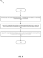
- FIG. 8 is a flow diagram of an example method 800 for assembling and/or manufacturing an apparatus for mitigating deformation of spring-loaded heatsinks.
- Method 800 may include the step of thermally coupling, via a spring-loaded heat exchanger, a designated area of a heatsink to a heat-emitting component mounted to a circuit board (810).
- Step 810 may be performed in a variety of ways, including any of those described above in connection with FIGS. 1-7 .
- a computing equipment manufacturer or subcontractor may thermally couple, via a spring-loaded heat exchanger, a designated area of a heatsink to a heat-emitting component mounted to a circuit board.
- Method 800 may also include the step of applying, to the spring-loaded heat exchanger, a plurality of springs that impart forces to support the thermal coupling between the designated area of the heatsink and the heat-emitting component (820).
- Step 820 may be performed in a variety of ways, including any of those described above in connection with FIGS. 1-7 .
- a computing equipment manufacturer or subcontractor may apply, to the spring-loaded heat exchanger, a plurality of springs that impart forces to support the thermal coupling between the designated area of the heatsink and the heat-emitting component.
- Method 800 may further include the step of applying, to the spring-loaded heat exchanger, a pressure plate that concentrates the forces imparted by the springs toward the designated area of the heatsink (830).
- Step 830 may be performed in a variety of ways, including any of those described above in connection with FIGS. 1-7 .
- a computing equipment manufacturer or subcontractor may apply, to the spring-loaded heat exchanger, a pressure plate that concentrates the forces imparted by the springs toward the designated area of the heatsink.
- an apparatus which includes (1) a heat-emitting component, (2) a heatsink that includes a designated area thermally coupled to the heat-emitting component, (3) a plurality of springs that apply forces that support the thermal coupling between the designated area of the heatsink and the heat-emitting component, and (4) a pressure plate that concentrates the forces applied by the springs toward the designated area of the heatsink.
- a heat-emitting component (2) a heatsink that includes a designated area thermally coupled to the heat-emitting component, (3) a plurality of springs that apply forces that support the thermal coupling between the designated area of the heatsink and the heat-emitting component, and (4) a pressure plate that concentrates the forces applied by the springs toward the designated area of the heatsink.
Landscapes
- Engineering & Computer Science (AREA)
- Physics & Mathematics (AREA)
- Theoretical Computer Science (AREA)
- Thermal Sciences (AREA)
- Microelectronics & Electronic Packaging (AREA)
- Human Computer Interaction (AREA)
- General Engineering & Computer Science (AREA)
- General Physics & Mathematics (AREA)
- Cooling Or The Like Of Electrical Apparatus (AREA)
- Cooling Or The Like Of Semiconductors Or Solid State Devices (AREA)
- Testing Of Individual Semiconductor Devices (AREA)
Abstract
Description
- Heatsinks are often a critical factor for electronic and mechanical devices. For example, a telecommunications device (such as a router or switch) may include circuit boards with electronic components that generate heat during operation, thereby causing the operating temperatures of those electronic components and/or neighboring components to rise. If the operating temperatures rise above a certain level, such components may overheat, malfunction, or even break. To prevent such issues, many electronic components may be equipped with heatsinks designed to transfer and/or dissipate heat. The heatsinks may include thermally conductive material that transfers heat away from the electronic components, thereby cooling the electronic components and/or enabling them to achieve higher performance.
- Heatsinks may also introduce certain risks into telecommunications devices. For example, a high-performing heatsink may be relatively heavy and/or represent a heavy load that is pressed against an electronic component via one or more springs. Unfortunately, the pressure applied to the heatsink by the springs may actually deform and/or bend the heatsink. Such deformation and/or bending of the heatsink may impair, degrade, and/or destroy the heatsink's performance (e.g., crashing a vapor chamber within the heatsink, demating the thermal coupling between the heatsink and the electronic component, and/or cracking the electronic component).
- Similarly, the pressure applied to the heatsink by the springs may actually deform, crack, and/or other damage the electronic component. Such deformation and/or damage of the electronic component may impair, degrade, and/or destroy the electronic component's performance. The instant disclosure, therefore, identifies and addresses a need for additional and improved apparatuses, systems, and methods for mitigating deformation of spring-loaded heatsinks and/or damaging electronic components cooled by such heatsinks.
- As will be described in greater detail below, the instant disclosure generally relates to apparatuses, systems, and methods for mitigating deformation of spring-loaded heatsinks. In one example, an apparatus for accomplishing such a task may include (1) a heat-emitting component, (2) a heatsink that includes a designated area thermally coupled to the heat-emitting component, (3) a plurality of springs that apply forces that support the thermal coupling between the designated area of the heatsink and the heat-emitting component, and (4) a pressure plate that concentrates the forces applied by the springs toward the designated area of the heatsink.
- Similarly, a system for accomplishing such a task may include (1) a computing device and (2) a spring-loaded heat exchanger incorporated in the computing device, wherein the spring-loaded heat exchanger comprising (A) a heat-emitting component, (B) a heatsink that includes a designated area thermally coupled to the heat-emitting component, (C) a plurality of springs that apply forces that support the thermal coupling between the designated area of the heatsink and the heat-emitting component, and (D) a pressure plate that concentrates the forces applied by the springs toward the designated area of the heatsink.
- A corresponding method may include (1) thermally coupling, via a spring-loaded heat exchanger, a designated area of a heatsink to a heat-emitting component mounted to a circuit board, (2) applying, to the spring-loaded heat exchanger, a plurality of springs that impart forces to support the thermal coupling between the designated area of the heatsink and the heat-emitting component, and (3) applying, to the spring-loaded heat exchanger, a pressure plate that concentrates the forces imparted by the springs toward the designated area of the heatsink.
- Features from any of the above-mentioned embodiments may be used in combination with one another in accordance with the general principles described herein. These and other embodiments, features, and advantages will be more fully understood upon reading the following detailed description in conjunction with the accompanying drawings and claims.
- The accompanying drawings illustrate a number of example embodiments and are a part of the specification. Together with the following description, these drawings demonstrate and explain various principles of the instant disclosure.
-
FIG. 1 is an illustration of an example apparatus for mitigating deformation of spring-loaded heatsinks in accordance with one or more embodiments of this disclosure. -
FIG. 2 is an illustration of an example heat-emitting component capable of being cooled by a spring-loaded heatsink in accordance with one or more embodiments of this disclosure. -
FIG. 3 is an illustration of an example apparatus for mitigating deformation of spring-loaded heatsinks in accordance with one or more embodiments of this disclosure. -
FIG. 4 is an illustration of an example apparatus for mitigating deformation of spring-loaded heatsinks in accordance with one or more embodiments of this disclosure. -
FIG. 5 is an illustration of an example apparatus for mitigating deformation of spring-loaded heatsinks in accordance with one or more embodiments of this disclosure. -
FIG. 6 is an illustration of an example device rack that holds rackmount computing devices in accordance with one or more embodiments of this disclosure. -
FIG. 7 is an illustration of an example rackmount computing device in accordance with one or more embodiments of this disclosure. -
FIG. 8 is a flow diagram of an example method for mitigating deformation of spring-loaded heatsinks in accordance with one or more embodiments of this disclosure. - Throughout the drawings, identical reference characters and descriptions indicate similar, but not necessarily identical, elements. While the example embodiments described herein are susceptible to various modifications and alternative forms, specific embodiments have been shown by way of example in the drawings and will be described in detail herein. However, the example embodiments described herein are not intended to be limited to the particular forms disclosed. Rather, the instant disclosure covers all modifications, equivalents, and alternatives falling within the scope of the appended claims.
- The present disclosure describes various apparatuses, systems, and methods for mitigating deformation of spring-loaded heatsinks. As will be explained in greater detail below, embodiments of the instant disclosure may include and/or involve a pressure plate that concentrates forces applied by a plurality of springs toward a designated area of a heatsink. For example, a spring-loaded heatsink may include and/or involve springs coupled to mounting posts that maintain the heatsink in place atop a heat-emitting component. In this example, the spring-loaded heatsink may include and/or involve a pressure plate that concentrates and/or focuses forces applied by those springs toward a pedestal of the heatsink that makes contact with the heat-emitting component.
- By concentrating and/or focusing the forces applied by those springs toward the pedestal, the pressure plate may safely align and/or transfer those forces to the pedestal pressing against the heat-emitting component, thereby preventing those forces from being distributed to portions of the heatsink that could potentially lead to deformation and/or bending of the heatsink or even damage to the heat-emitting component. As a result, the pressure plate may enable the spring-loaded heatsink to maintain a secure thermal coupling with the heat-emitting component, to improve or maximize the heatsink's performance, to prolong the structural integrity or thermal-transfer capabilities of the heatsink, and/or to protect the functionality of the heat-emitting component.
- The following will provide, with reference to
FIGS. 1-7 , detailed descriptions of example components, apparatuses, systems, configurations, and/or implementations for mitigating deformation of spring-loaded heatsinks. In addition, the discussion corresponding toFIG. 8 will provide detailed descriptions of an example method for assembling and/or manufacturing apparatuses for mitigating deformation of spring-loaded heatsinks. -
FIG. 1 illustrates an example apparatus 100 for mitigating deformation of spring-loaded heatsinks. As illustrated inFIG. 1 , example apparatus 100 may include and/or represent various features, components, and/or devices that make up and/or form a spring-loaded heatsink. For example, apparatus 100 may include and/or represent aheatsink 104, springs 106(1) and 106(2), and apressure plate 108. In this example,heatsink 104 may be spring-loaded by springs 106(1) and 106(2) to press against a heat-emitting component 102 coupled to acircuit board 110. Specifically,heatsink 104 may include and/or incorporate a designated area (e.g., a pedestal 112) that makes physical contact and/or interfaces with a top surface of heat-emitting component 102. AlthoughFIG. 1 illustrates only two springs, apparatus 100 may also include and/or represent one or more additional springs that contribute to spring-loading heatsink 104 to press against heat-emitting component 102. - As further illustrated in
FIG. 1 , example apparatus 100 may include and/or represent mounting posts 130(1) and 130(2) that maintain and/or holdheatsink 104 in place atop heat-emitting component 102 by way ofpressure plate 108. AlthoughFIG. 1 illustrates only two mounting posts, apparatus 100 may also include and/or represent one or more additional mounting posts that contribute to maintaining and/or holdingheatsink 104 in place atop heat-emitting component 102 by way ofpressure plate 108. - In some examples, mounting posts 130(1) and 130(2) may mate and/or interface with a
backing plate 114 applied and/or positionedopposite circuit board 110 to pressurize and/or lockpressure plate 108 againstheatsink 104 via springs 106 (1) and 106(2). In these examples, springs 106(1) and 106(2) may be coupled to mounting posts 130(1) and 130(2), respectively, and apply forces that support the thermal coupling between the designated area (e.g., pedestal 112) ofheatsink 104 and heat-emitting component 102. In one example,pressure plate 108 may concentrate and/or focus those forces applied by springs 106(1) and 106(2) toward the designated area ofheatsink 104. By doing so,pressure plate 108 may safely align and/or transfer those forces to the designated area ofheatsink 104 pressing against heat-emitting component 102, thereby preventing those forces from being distributed to portions ofheatsink 104 that could potentially lead to deformation and/or bending ofheatsink 104 or even damage to heat-emitting component 102. - In some examples,
heatsink 104 may include and/or represent any type or form of device, structure, and/or mechanism designed to conduct, transfer, absorb, and/or sink heat. Heatsink 104 may include and/or contain a variety of thermally conductive materials. Examples of such thermally conductive materials include, without limitation, copper, aluminum, diamond, silver, gold, alloys of one or more of the same, combinations or variations of one or more of the same, and/or any other suitable materials. - In some examples,
heatsink 104 may contain and/or be composed of a series of ridges or corrugations extending from a base. For example,heatsink 104 may include and/or incorporate a finned and/or pin fin configuration or design. This configuration may increase the surface area of the conductive material within the heatsink, thereby increasing the amount of heat dissipated by the same. Heatsink 104 may also include any additional or alternative structure designed to facilitate and/or increase heat dissipation, such as wicks, heatpipes, and/or vapor chambers. - In some examples,
heatsink 104 may include and/or incorporatepedestal 112, which interfaces and/or makes contact with heat-emitting component 102. In one example,pedestal 112 may be dimensioned to substantially match the size of heat-emitting component 102. For example,pedestal 112 may be sized to cover the top surface of heat-emittingcomponent 102, thereby providing an area sufficient to achieve the necessary thermal transfer. In this example,pedestal 112 may be positioned atop heat-emittingcomponent 102 to form and/or establish a thermal coupling with heat-emittingcomponent 102. - In some examples, springs 106(1) and 106(2) may each include and/or represent any type or form of mechanical apparatus and/or device capable of storing, absorbing, and/or releasing energy or force. In one example, spring 106(1) and 106(2) may each include and/or represent a compression coil spring. Additional examples of springs 106(1) and 106(2) include, without limitation, tension springs, extension springs, horseshoe springs, torsion springs, coil springs, constant-force springs, gas springs, combinations or variations of one or more of the same, and/or any other suitable springs.
- Spring 106(1) and 106(2) may include and/or contain a variety of materials. Examples of such materials include, without limitation, metals, copper, aluminum, alloys, plastics, polymers, combinations or variations of one or more of the same, and/or any other suitable materials.
- In some examples,
pressure plate 108 may include and/or represent any type or form of physical structure and/or mechanism that pressurizesheatsink 104 to heat-emittingelectrical component 102. In one example,pressure plate 108 may include and/or incorporate acontact area 122 that presses against and/or makes contact a top surface (e.g., a fin structure) of withheatsink 104. In this example,contact area 122 ofpressure plate 108 may be positioned atopheatsink 104opposite pedestal 112 ofheatsink 104. By positioningpressure plate 108 atopheatsink 104 in this way, the boundary ofcontact area 122 may substantially align and/or coincide with the boundary ofpedestal 112 ofheatsink 104. In certain examples,pressure plate 108 may reside and/or sit between springs 106(1) and 106(2) applied to mounting posts 130(1) and 130(2) andheatsink 104. This position and/or configuration ofpressure plate 108 may facilitate spring-loadingpressure plate 108 toward the designated area ofheatsink 104. Thus,pressure plate 108 may avoid making contact withheatsink 104 outside ofcontact area 122 to protect the structural integrity of heatsink 104(1). - In some examples,
circuit board 110 may include and/or represents any piece of insulating material that facilitates mounting (e.g., mechanical support) and/or interconnection (e.g., electrical coupling) of electrical and/or electronic components. In one example,circuit board 110 may include and/or represent a Printed Circuit Board (PCB). Examples ofcircuit board 102 include, without limitation, single-sided boards, double-sided boards, multilayer boards, motherboards, linecards, backplanes, midplanes, and/or any other suitable type of circuit board. Various components (e.g., heat-emitting component 102) may be laminated, etched, attached, soldered, and/or otherwise coupled tocircuit board 110. - In some examples,
circuit board 110 may include various electrically conductive layers and/or traces (not necessarily illustrated inFIG. 1 ). Such conductive layers and/or traces may include and/or represent electrically conductive materials. Examples of such electrically conductive materials include, without limitation, copper, aluminum, silver, gold, alloys of one or more of the same, combinations or variations of one or more of the same, and/or any other suitable materials. - In one example, each layer may include and/or represent a conductive plane that is etched and/or laid during the fabrication phase to produce various conductive traces throughout
circuit board 110. In this example, the etched and/or laid conductive traces may be separated from and/or interconnected with one another as necessary to form one or more circuits that incorporate electrical components and/or electronics acrosscircuit board 110. - In some examples, backing
plate 114 may include and/or represent include and/or represent any type or form of physical structure and/or mechanism that pressurizesheatsink 104 to heat-emittingelectrical component 102. In one example, backingplate 114 may provide support and/or additional structure to the spring-loaded heatsink. In one example,heatsink 104 may be applied to the top side ofcircuit board 110 inFIG. 1 to facilitate contact with heat-emittingcomponent 102, andbacking plate 114 may be applied to the bottom side ofcircuit board 110 inFIG. 1 . In this example, backingplate 114 and/orpressure plate 108 may be secured in place by mounting posts 130(1) and 130(2). - In some examples, mounting posts 130(1) and 130(2) may each include and/or represent any type or form of attachment, mounting, and/or coupling structure or means. For example, mounting posts 130(1) and 130(2) may each include and/or represent a pairing of a screw and threaded post or standoff. In another example, mounting posts 130(1) and 130(2) may each include and/or represent a pairing of a pin and an extension post or bracket.
- Mounting posts 130(1) and 130(2) may include and/or contain a variety of materials. Examples of such materials include, without limitation, metals, copper, aluminum, alloys, plastics, polymers, combinations or variations of one or more of the same, and/or any other suitable materials.
-
FIG. 2 illustrates an example implementation of heat-emittingcomponent 102, which is capable of being cooled by a spring-loaded heatsink. In some examples, heat-emittingcomponent 102 may include and/or represent any type or form of device, component, and/or circuit that emits heat. In one example, heat-emittingcomponent 102 may include and/or represent an integrated circuit. Additional examples of heat-emittingcomponent 102 include, without limitation, Central Processing Units (CPUs), microprocessors, microcontrollers, Field-Programmable Gate Arrays (FPGAs) that implement softcore processors, Application-Specific Integrated Circuits (ASICs), memories (e.g., high-bandwidth memory devices), portions of one or more of the same, variations or combinations of one or more of the same, and/or any other suitable heat-emitting component. -
FIG. 3 illustrates an example apparatus 300 for mitigating deformation of spring-loaded heatsinks. As illustrated inFIG. 3 , example apparatus 300 may include and/or represent various features, components, and/or devices that make up and/or form a spring-loaded heatsink assembly. In some examples, apparatus 300 may include and/or represent any of the features, components, and/or devices described above in connection with apparatus 100 inFIG. 1 . - In some examples, apparatus 300 may include and/or represent a heatsink 104(1) and a heatsink 104(2), springs 304(1) and springs 304(2), and
pressure plate 108. In this example, heatsink 104(1) may be spring-loaded by springs 304(1) to press against a heat-emitting component coupled tocircuit board 110. In addition, heatsink 104(2) may be spring-loaded by springs 304(2) to press against an additional heat-emitting component coupled tocircuit board 110. In one example, mounting posts may securepressure plate 108 tobacking plate 114, which is applied and/or positionedopposite circuit board 110 to pressurize and/or lockpressure plate 108 against heatsinks 104(1) and 104(2) via springs 304(1) and 304(2), respectively. - In some examples,
pressure plate 108 may include and/or represent spring-loaded extensions 318(1) and 318(2) that concentrate forces applied by springs 304(1) and 304(2) toward designated areas (e.g., pedestals) of heatsinks 104(1) and 104(2), respectively. For example, spring-loaded extension 318(1) may include and/or incorporate springs 304(1) that press and/or extend another surface and/or platform frompressure plate 108. In this example, the extensible surface and/or platform may constitute and/or represent a contact area positioned atop heatsink 104(1) opposite the pedestal of heatsink 104(1). By positioning the contact area atop heatsink 104(1) in this way, the boundary of the contact area may substantially align with the boundary of the pedestal of heatsink 104(1). Thus,pressure plate 108 may avoid making contact with heatsink 104(1) outside of the contact area to protect the structural integrity of heatsink 104(1). - As another example, spring-loaded extension 318(2) may include and/or incorporate springs 304(2) that press and/or extend another surface and/or platform from
pressure plate 108. In this example, the extensible surface and/or platform may constitute and/or represent another contact area positioned atop heatsink 104(2) opposite the pedestal of heatsink 104(2). By positioning the other contact area atop heatsink 104(2) in this way, the boundary of the other contact area may substantially align with the boundary of the pedestal of heatsink 104(2). Thus,pressure plate 108 may avoid making contact with heatsink 104(2) outside of the contact area to protect the structural integrity of heatsink 104(2). -
FIG. 4 illustrates an example apparatus 400 for mitigating deformation of spring-loaded heatsinks. As illustrated inFIG. 4 , example apparatus 400 may include and/or represent various features, components, and/or devices that make up and/or form a spring-loaded heatsink. For example, apparatus 400 may include and/or representheatsink 104, springs 106(1) and 106(2), andpressure plate 108. In some examples, apparatus 400 may include and/or represent any of the features, components, and/or devices described above in connection with apparatus 100 inFIG. 1 and/or apparatus 300 inFIG. 3 . - In some examples,
heatsink 104 may include and/or represent abase 406. In one example,base 406 ofheatsink 104 may include and/or incorporate avapor chamber 404. Additionally or alternatively,heatsink 104 may include and/or represent a plurality offins 402 coupled tobase 406. - In some examples,
heatsink 104 may include and/or represent areinforcement pillar 408 that extends, runs, and/or spans across at least one portion ofvapor chamber 404. In one example,reinforcement pillar 408 may strengthen and/or improve the structural integrity ofbase 406 to withstand the pressure and/or compression applied by springs 106(1) and 106(2) without collapsing and/or breaking down. Additionally or alternatively,heatsink 104 may include and/or represent areinforcement standoff 410 that extends, runs, and/or spans at least the length of fins 402 (or slightly higher) frombase 406. In certain examples,reinforcement standoff 410 may strengthen and/or improve the structural integrity offins 402 to withstand the pressure applied by springs 106(1) and 106(2) without collapsing and/or breaking down. For example,pressure plate 108 may make direct contact withreinforcement standoff 410 instead offins 402. By doing so,pressure plate 108 may concentrate the forces applied by springs 106(1) and 106(2) toward the designated area ofheatsink 104 viareinforcement standoff 410 without applying toomuch pressure fins 402 or risking damage tofins 402. -
Reinforcement pillar 408 and/orreinforcement standoff 410 may include and/or contain a variety of materials. Examples of such materials include, without limitation, metals, steels, copper, aluminum, alloys, plastics, polymers, combinations or variations of one or more of the same, and/or any other suitable materials. -
FIG. 5 illustrates an example apparatus 500 for mitigating deformation of spring-loaded heatsinks. As illustrated inFIG. 5 , example apparatus 500 may include and/or represent various features, components, and/or devices that make up and/or form a spring-loaded heatsink. For example, apparatus 500 may include and/or representheatsink 104, springs 106(1) and 106(2), andpressure plate 108. In some examples, apparatus 500 may include and/or represent any of the features, components, and/or devices described above in connection with apparatus 100 inFIG. 1 , apparatus 300 inFIG. 3 , and/or apparatus 400 inFIG. 4 . - In some examples,
pressure plate 108 may include and/or form anopening 508 fitted to accommodate aheatsink 504. For example,heatsink 504 may include and/or represent asegment 506 that passes through opening 504 ofpressure plate 108 to make contact with a heat-emittingcomponent 510. In this example, by making such contact,segment 506 may thermallycouple heatsink 504 to heat-emittingcomponent 510. - In some examples,
heatsinks heatsinks heatsinks components -
FIG. 6 illustrates anexample network rack 600 that houses and/or holds rackmount network devices. As illustrated inFIG. 6 ,network rack 600 may include various holes for mounting rackmount network devices. In this example,network rack 600 may house and/or maintain rackmount network devices of various sizes. These sizes may be represented in rack units (such as 1U, 2U, 3U, 4U, 5U, etc.). -
FIG. 7 illustrates an examplerackmount computing device 700 that fits withinnetwork rack 600 inFIG. 6 . As illustrated inFIG. 7 ,rackmount computing device 700 may be configured to fit withinnetwork rack 600 inFIG. 6 . Accordingly,rackmount computing device 700 may be housed bynetwork rack 600. In this example,rackmount computing device 700 may represent a rackmount switch or router.Rackmount computing device 700 may house and/or incorporate all or portions of apparatuses 100, 300, 400, and 500. In other words,rackmount computing device 700 may contain all the spring-loaded heatsink assemblies and/or corresponding components included in any one of those apparatuses. -
FIG. 8 is a flow diagram of anexample method 800 for assembling and/or manufacturing an apparatus for mitigating deformation of spring-loaded heatsinks.Method 800 may include the step of thermally coupling, via a spring-loaded heat exchanger, a designated area of a heatsink to a heat-emitting component mounted to a circuit board (810). Step 810 may be performed in a variety of ways, including any of those described above in connection withFIGS. 1-7 . For example, a computing equipment manufacturer or subcontractor may thermally couple, via a spring-loaded heat exchanger, a designated area of a heatsink to a heat-emitting component mounted to a circuit board. -
Method 800 may also include the step of applying, to the spring-loaded heat exchanger, a plurality of springs that impart forces to support the thermal coupling between the designated area of the heatsink and the heat-emitting component (820). Step 820 may be performed in a variety of ways, including any of those described above in connection withFIGS. 1-7 . For example, a computing equipment manufacturer or subcontractor may apply, to the spring-loaded heat exchanger, a plurality of springs that impart forces to support the thermal coupling between the designated area of the heatsink and the heat-emitting component. -
Method 800 may further include the step of applying, to the spring-loaded heat exchanger, a pressure plate that concentrates the forces imparted by the springs toward the designated area of the heatsink (830). Step 830 may be performed in a variety of ways, including any of those described above in connection withFIGS. 1-7 . For example, a computing equipment manufacturer or subcontractor may apply, to the spring-loaded heat exchanger, a pressure plate that concentrates the forces imparted by the springs toward the designated area of the heatsink. - Thus, from one perspective, there has now been described an apparatus which includes (1) a heat-emitting component, (2) a heatsink that includes a designated area thermally coupled to the heat-emitting component, (3) a plurality of springs that apply forces that support the thermal coupling between the designated area of the heatsink and the heat-emitting component, and (4) a pressure plate that concentrates the forces applied by the springs toward the designated area of the heatsink. Various other apparatuses, systems, and methods are also disclosed.
- While the foregoing disclosure sets forth various embodiments using specific block diagrams, flowcharts, and examples, each block diagram component, flowchart step, operation, and/or component described and/or illustrated herein may be implemented, individually and/or collectively, using a wide range of hardware, software, or firmware (or any combination thereof) configurations. In addition, any disclosure of components contained within other components should be considered example in nature since many other architectures can be implemented to achieve the same functionality.
- The process parameters and sequence of the steps described and/or illustrated herein are given by way of example only and can be varied as desired. For example, while the steps illustrated and/or described herein may be shown or discussed in a particular order, these steps do not necessarily need to be performed in the order illustrated or discussed. The various example methods described and/or illustrated herein may also omit one or more of the steps described or illustrated herein or include additional steps in addition to those disclosed.
- The preceding description has been provided to enable others skilled in the art to best utilize various aspects of the example embodiments disclosed herein. This example description is not intended to be exhaustive or to be limited to any precise form disclosed. Many modifications and variations are possible without departing from the scope of the instant disclosure. The embodiments disclosed herein should be considered in all respects illustrative and not restrictive. Reference should be made to the appended claims and their equivalents in determining the scope of the instant disclosure.
- Unless otherwise noted, the terms "connected to" and "coupled to" (and their derivatives), as used in the specification and claims, are to be construed as permitting both direct and indirect (i.e., via other elements or components) connection. In addition, the terms "a" or "an," as used in the specification and claims, are to be construed as meaning "at least one of." Finally, for ease of use, the terms "including" and "having" (and their derivatives), as used in the specification and claims, are interchangeable with and have the same meaning as the word "comprising."
- Further examples of feature combinations taught by the present disclosure are set out in the following numbered clauses:
- 1. An apparatus comprising:
- a heat-emitting component;
- a heatsink that includes a designated area thermally coupled to the heat-emitting component;
- a plurality of springs that apply forces that support the thermal coupling between the designated area of the heatsink and the heat-emitting component; and
- a pressure plate that concentrates the forces applied by the springs toward the designated area of the heatsink.
- 2. The apparatus of
clause 1, wherein the designated area of the heatsink comprises a pedestal that:- makes contact with the heat-emitting component; and
- is dimensioned to substantially match a size of the heat-emitting component.
- 3. The apparatus of
clause 2, wherein:- the pressure plate comprises a contact area that:
- makes contact with the heatsink; and
- is positioned atop the heatsink opposite the pedestal of the heatsink; and
- the pedestal of the heatsink comprises a boundary that substantially aligns with a boundary of the contact area of the pressure plate.
- the pressure plate comprises a contact area that:
- 4. The apparatus of any preceding clause, wherein the springs are applied to a plurality of mounting posts that maintain the heatsink in place atop the heat-emitting component.
- 5. The apparatus of any preceding clause, wherein the pressure plate resides between the springs applied to the mounting posts and the heatsink to spring-load the pressure plate toward the designated area of the heatsink.
- 6. The apparatus of any preceding clause, wherein the pressure plate comprises a spring-loaded extension that concentrates the forces applied by the springs toward the designated area of the heatsink, wherein the spring-loaded extension of the pressure plate incorporates the springs.
- 7. The apparatus of clause 6, further comprising:
- an additional heat-emitting component;
- an additional heatsink that includes a designated area thermally coupled to the additional heat-emitting component; and
- a plurality of additional springs that apply forces that support the thermal coupling between the designated area of the additional heatsink and the additional heat-emitting component; and
- 8. The apparatus of any preceding clause, wherein the springs comprises a set of compression coil springs.
- 9. The apparatus of any preceding clause, wherein the heatsink comprises at least one of:
- a plurality of fins; and
- a vapor chamber.
- 10. The apparatus of any preceding clause, wherein the heatsink comprises:
- a base;
- a vapor chamber incorporated in the base;
- a plurality of fins coupled to the base;
- at least one reinforcement pillar that extends across at least one portion of the vapor chamber; and
- at least one reinforcement standoff that is coupled to the base and extends at least the length of the fins from the base.
- 11. The apparatus of clause 10, wherein the pressure plate makes contact with the reinforcement standoff and concentrates the forces applied by the springs toward the designated area of the heatsink via the reinforcement standoff.
- 12. The apparatus of any preceding clause, wherein the pressure plate forms an opening; and further comprising:
- an additional heat-emitting component; and
- an additional heatsink that includes a segment that passes through the opening of the pressure plate to thermally couple the additional heatsink to the additional heat-emitting component.
- 13. A system comprising:
- a computing device; and
- a spring-loaded heat exchanger incorporated in the computing device, wherein the spring-loaded heat exchanger comprising:
- a heat-emitting component;
- a heatsink that includes a designated area thermally coupled to the heat-emitting component;
- a plurality of springs that apply forces that support the thermal coupling between the designated area of the heatsink and the heat-emitting component; and
- a pressure plate that concentrates the forces applied by the springs toward the designated area of the heatsink.
- 14. The system of clause 13, wherein the designated area of the heatsink comprises a pedestal that:
- makes contact with the heat-emitting component; and
- is dimensioned to substantially match a size of the heat-emitting component.
- 15. The system of clause 14, wherein:
- the pressure plate comprises a contact area that:
- makes contact with the heatsink; and
- is positioned atop the heatsink opposite the pedestal of the heatsink; and
- the pedestal of the heatsink comprises a boundary that substantially aligns with a boundary of the contact area of the pressure plate.
- the pressure plate comprises a contact area that:
- 16. The system of any of clauses 13 to 15, wherein the springs are applied to a plurality of mounting posts that maintain the heatsink in place atop the heat-emitting component.
- 17. The system of any of clauses 13 to 16, wherein the pressure plate resides between the springs applied to the mounting posts and the heatsink to spring-load the pressure plate toward the designated area of the heatsink.
- 18. The system of any of clauses 13 to 17, wherein the pressure plate comprises a spring-loaded extension that concentrates the forces applied by the springs toward the designated area of the heatsink, wherein the spring-loaded extension of the pressure plate incorporates the springs.
- 19. The system of clause 18, wherein the spring-loaded heat exchanger further comprising:
- an additional heat-emitting component;
- an additional heatsink that includes a designated area thermally coupled to the additional heat-emitting component; and
- a plurality of additional springs that apply forces that support the thermal coupling between the designated area of the additional heatsink and the additional heat-emitting component; and
- 20. A method comprising:
- thermally coupling, via a spring-loaded heat exchanger, a designated area of a heatsink to a heat-emitting component mounted to a circuit board;
- applying, to the spring-loaded heat exchanger, a plurality of springs that impart forces to support the thermal coupling between the designated area of the heatsink and the heat-emitting component; and
- applying, to the spring-loaded heat exchanger, a pressure plate that concentrates the forces imparted by the springs toward the designated area of the heatsink.
Claims (15)
- An apparatus comprising:a heat-emitting component;a heatsink that includes a designated area thermally coupled to the heat-emitting component;a plurality of springs that apply forces that support the thermal coupling between the designated area of the heatsink and the heat-emitting component; anda pressure plate that concentrates the forces applied by the springs toward the designated area of the heatsink.
- The apparatus of claim 1, wherein the designated area of the heatsink comprises a pedestal that:makes contact with the heat-emitting component; andis dimensioned to substantially match a size of the heat-emitting component.
- The apparatus of claim 2, wherein:the pressure plate comprises a contact area that:makes contact with the heatsink; andis positioned atop the heatsink opposite the pedestal of the heatsink; andthe pedestal of the heatsink comprises a boundary that substantially aligns with a boundary of the contact area of the pressure plate.
- The apparatus of any preceding claim, wherein the springs are applied to a plurality of mounting posts that maintain the heatsink in place atop the heat-emitting component.
- The apparatus of any preceding claim, wherein the pressure plate resides between the springs applied to the mounting posts and the heatsink to spring-load the pressure plate toward the designated area of the heatsink.
- The apparatus of any preceding claim, wherein the pressure plate comprises a spring-loaded extension that concentrates the forces applied by the springs toward the designated area of the heatsink, wherein the spring-loaded extension of the pressure plate incorporates the springs.
- The apparatus of claim 6, further comprising:an additional heat-emitting component;an additional heatsink that includes a designated area thermally coupled to the additional heat-emitting component; anda plurality of additional springs that apply forces that support the thermal coupling between the designated area of the additional heatsink and the additional heat-emitting component; andwherein the pressure plate further comprises an additional spring-loaded extension that concentrates the forces applied by the additional springs toward the designated area of the additional heatsink, wherein the additional spring-loaded extension of the pressure plate incorporates the additional springs.
- The apparatus of any preceding claim, wherein the springs comprises a set of compression coil springs.
- The apparatus of any preceding claim, wherein the heatsink comprises at least one of:a plurality of fins; anda vapor chamber.
- The apparatus of any preceding claim, wherein the heatsink comprises:a base;a vapor chamber incorporated in the base;a plurality of fins coupled to the base;at least one reinforcement pillar that extends across at least one portion of the vapor chamber; andat least one reinforcement standoff that is coupled to the base and extends at least the length of the fins from the base.
- The apparatus of claim 10, wherein the pressure plate makes contact with the reinforcement standoff and concentrates the forces applied by the springs toward the designated area of the heatsink via the reinforcement standoff.
- The apparatus of any preceding claim, wherein the pressure plate forms an opening; and further comprising:an additional heat-emitting component; andan additional heatsink that includes a segment that passes through the opening of the pressure plate to thermally couple the additional heatsink to the additional heat-emitting component.
- A system comprising:a computing device; anda spring-loaded heat exchanger incorporated in the computing device, wherein the spring-loaded heat exchanger comprising:a heat-emitting component;a heatsink that includes a designated area thermally coupled to the heat-emitting component;a plurality of springs that apply forces that support the thermal coupling between the designated area of the heatsink and the heat-emitting component; anda pressure plate that concentrates the forces applied by the springs toward the designated area of the heatsink.
- The system of claim 13, wherein the designated area of the heatsink comprises a pedestal that:makes contact with the heat-emitting component; andis dimensioned to substantially match a size of the heat-emitting component.
- A method comprising:thermally coupling, via a spring-loaded heat exchanger, a designated area of a heatsink to a heat-emitting component mounted to a circuit board;applying, to the spring-loaded heat exchanger, a plurality of springs that impart forces to support the thermal coupling between the designated area of the heatsink and the heat-emitting component; andapplying, to the spring-loaded heat exchanger, a pressure plate that concentrates the forces imparted by the springs toward the designated area of the heatsink.
Applications Claiming Priority (1)
| Application Number | Priority Date | Filing Date | Title |
|---|---|---|---|
| US17/532,633 US11991863B2 (en) | 2021-11-22 | 2021-11-22 | Apparatus, system, and method for mitigating deformation of spring-loaded heatsinks |
Publications (1)
| Publication Number | Publication Date |
|---|---|
| EP4184565A1 true EP4184565A1 (en) | 2023-05-24 |
Family
ID=80624928
Family Applications (1)
| Application Number | Title | Priority Date | Filing Date |
|---|---|---|---|
| EP22156148.3A Pending EP4184565A1 (en) | 2021-11-22 | 2022-02-10 | Apparatus, system, and method for mitigating deformation of spring-loaded heatsinks |
Country Status (3)
| Country | Link |
|---|---|
| US (1) | US11991863B2 (en) |
| EP (1) | EP4184565A1 (en) |
| CN (1) | CN116156831B (en) |
Cited By (1)
| Publication number | Priority date | Publication date | Assignee | Title |
|---|---|---|---|---|
| CN116984773A (en) * | 2023-09-26 | 2023-11-03 | 江苏辅星电子有限公司 | Copper mesh capillary element assembly equipment and method |
Citations (4)
| Publication number | Priority date | Publication date | Assignee | Title |
|---|---|---|---|---|
| US20090083972A1 (en) * | 2007-09-27 | 2009-04-02 | Colbert John L | Electronic Assembly and Techniques for Installing a Heatsink in an Electronic Assembly |
| US20160284624A1 (en) * | 2013-03-21 | 2016-09-29 | Nec Corporation | Heat sink structure, semiconductor device and heat sink mounting method |
| US20180054915A1 (en) * | 2015-06-02 | 2018-02-22 | International Business Machines Corporation | Heat sink attachment on existing heat sinks |
| EP3792959A1 (en) * | 2019-09-10 | 2021-03-17 | Aptiv Technologies Limited | Heat exchanger for electronics |
Family Cites Families (22)
| Publication number | Priority date | Publication date | Assignee | Title |
|---|---|---|---|---|
| US6212074B1 (en) * | 2000-01-31 | 2001-04-03 | Sun Microsystems, Inc. | Apparatus for dissipating heat from a circuit board having a multilevel surface |
| US20010055198A1 (en) * | 2000-06-24 | 2001-12-27 | Samsung Electro-Mechanics Co., Ltd. | Heat sink |
| US6545879B1 (en) * | 2002-01-10 | 2003-04-08 | Tyco Electronics Corporation | Method and apparatus for mounting a lidless semiconductor device |
| US6798663B1 (en) * | 2003-04-21 | 2004-09-28 | Hewlett Packard Development Company, L.P. | Heat sink hold-down with fan-module attach location |
| US7042727B2 (en) * | 2003-09-26 | 2006-05-09 | Intel Corporation | Heat sink mounting and interface mechanism and method of assembling same |
| US7777329B2 (en) * | 2006-07-27 | 2010-08-17 | International Business Machines Corporation | Heatsink apparatus for applying a specified compressive force to an integrated circuit device |
| CN101193536A (en) * | 2006-11-29 | 2008-06-04 | 英业达股份有限公司 | Heat sink structure and assembling jig thereof |
| US7474530B2 (en) * | 2007-01-10 | 2009-01-06 | Sun Microsystems, Inc. | High-load even pressure heatsink loading for low-profile blade computer applications |
| JP2012104520A (en) * | 2010-11-05 | 2012-05-31 | Mitsubishi Electric Corp | Component float preventing tool |
| US20130032324A1 (en) * | 2011-08-03 | 2013-02-07 | Aldridge Russell W | Thermal solution with spring-loaded interface |
| JP2014165231A (en) * | 2013-02-22 | 2014-09-08 | Fujitsu Ltd | Electronic component unit and fixing structure |
| JP6271184B2 (en) * | 2013-08-14 | 2018-01-31 | 竹内工業株式会社 | Heat sink retainer |
| US10170391B2 (en) * | 2014-05-09 | 2019-01-01 | Lenovo Enterprise Solutions (Singapore) Pte. Ltd. | Backside initiated uniform heat sink loading |
| US10477728B2 (en) * | 2017-12-27 | 2019-11-12 | Juniper Networks, Inc | Apparatus, system, and method for cooling devices containing multiple components |
| US10440812B2 (en) * | 2018-02-26 | 2019-10-08 | Dell Products L. P. | Heatsink mounting system to maintain a relatively uniform amount of pressure on components of a circuit board |
| US10304755B1 (en) * | 2018-03-27 | 2019-05-28 | Juniper Networks, Inc | Apparatus, system, and method for mitigating electromagnetic radiation leaks in double-decker heatsinks |
| US10788637B2 (en) * | 2018-12-21 | 2020-09-29 | Juniper Networks, Inc. | Apparatus, system, and method for dissipating heat emitted by individual communication modules via ganged heat exchangers |
| CN110794641A (en) * | 2019-09-24 | 2020-02-14 | 深圳市火乐科技发展有限公司 | Heat dissipation device and projection equipment |
| US11129302B1 (en) * | 2019-09-30 | 2021-09-21 | Juniper Networks, Inc | Apparatus, system, and method for electromagnetic interference mitigation in split heatsink technologies |
| US10978372B1 (en) * | 2019-11-11 | 2021-04-13 | Google Llc | Heat sink load balancing apparatus |
| US11456231B2 (en) * | 2021-01-18 | 2022-09-27 | Fortinet, Inc. | Heatsink arrangement for integrated circuit assembly and method for assembling thereof |
| CN214251284U (en) * | 2021-01-25 | 2021-09-21 | 深圳誉鸿锦科技有限公司 | Sealed infrared temperature sensor |
-
2021
- 2021-11-22 US US17/532,633 patent/US11991863B2/en active Active
-
2022
- 2022-02-09 CN CN202210121276.XA patent/CN116156831B/en active Active
- 2022-02-10 EP EP22156148.3A patent/EP4184565A1/en active Pending
Patent Citations (4)
| Publication number | Priority date | Publication date | Assignee | Title |
|---|---|---|---|---|
| US20090083972A1 (en) * | 2007-09-27 | 2009-04-02 | Colbert John L | Electronic Assembly and Techniques for Installing a Heatsink in an Electronic Assembly |
| US20160284624A1 (en) * | 2013-03-21 | 2016-09-29 | Nec Corporation | Heat sink structure, semiconductor device and heat sink mounting method |
| US20180054915A1 (en) * | 2015-06-02 | 2018-02-22 | International Business Machines Corporation | Heat sink attachment on existing heat sinks |
| EP3792959A1 (en) * | 2019-09-10 | 2021-03-17 | Aptiv Technologies Limited | Heat exchanger for electronics |
Cited By (2)
| Publication number | Priority date | Publication date | Assignee | Title |
|---|---|---|---|---|
| CN116984773A (en) * | 2023-09-26 | 2023-11-03 | 江苏辅星电子有限公司 | Copper mesh capillary element assembly equipment and method |
| CN116984773B (en) * | 2023-09-26 | 2023-12-12 | 江苏辅星电子有限公司 | Copper mesh capillary element assembly equipment and method |
Also Published As
| Publication number | Publication date |
|---|---|
| CN116156831A (en) | 2023-05-23 |
| US11991863B2 (en) | 2024-05-21 |
| CN116156831B (en) | 2025-11-21 |
| US20230164956A1 (en) | 2023-05-25 |
Similar Documents
| Publication | Publication Date | Title |
|---|---|---|
| US7742307B2 (en) | High performance power device | |
| EP1508916B1 (en) | Apparatus for cooling semiconductor devices attached to a printed circuit board | |
| US7420808B2 (en) | Liquid-based cooling system for cooling a multi-component electronics system | |
| EP2561733B1 (en) | Wedge lock for use with a single board computer, a single board computer, and method of assembling a computer system | |
| EP1827070B1 (en) | Thermal management of electronic devices | |
| US7881060B2 (en) | Heat-dissipation module and electronic apparatus having the same | |
| KR101614227B1 (en) | Compact thermal module | |
| US20090027859A1 (en) | Surface mounted heat sink and electromagnetic shield | |
| JPH02305498A (en) | Cold plate assembly | |
| US7751918B2 (en) | Methods for configuring tubing for interconnecting in-series multiple liquid-cooled cold plates | |
| US6101094A (en) | Printed circuit board with integrated cooling mechanism | |
| CN1248355A (en) | Multi-deck power converter module | |
| JPH1093280A (en) | Electronic enclosure with electromagnetic energy encapsulation and heat removal properties | |
| CN111033724B (en) | Circuit block assembly | |
| US20140085824A1 (en) | Micro-die natural convection cooling system | |
| US20080198557A1 (en) | Heat-dissipating module | |
| CN111064344A (en) | Power module with bottom metal heat dissipation substrate | |
| US6700195B1 (en) | Electronic assembly for removing heat from a flip chip | |
| US11991863B2 (en) | Apparatus, system, and method for mitigating deformation of spring-loaded heatsinks | |
| WO2019220485A1 (en) | Electric power converter | |
| JP4438526B2 (en) | Power component cooling system | |
| JP2020174116A (en) | Heat sink fixing member and electronic device | |
| JPH06163758A (en) | Heat dissipation structure by IC socket using shape memory alloy spring | |
| US9622385B2 (en) | Method of assembling a heat dissipating module of an electronic device | |
| JP7115032B2 (en) | substrate |
Legal Events
| Date | Code | Title | Description |
|---|---|---|---|
| PUAI | Public reference made under article 153(3) epc to a published international application that has entered the european phase |
Free format text: ORIGINAL CODE: 0009012 |
|
| STAA | Information on the status of an ep patent application or granted ep patent |
Free format text: STATUS: THE APPLICATION HAS BEEN PUBLISHED |
|
| AK | Designated contracting states |
Kind code of ref document: A1 Designated state(s): AL AT BE BG CH CY CZ DE DK EE ES FI FR GB GR HR HU IE IS IT LI LT LU LV MC MK MT NL NO PL PT RO RS SE SI SK SM TR |
|
| STAA | Information on the status of an ep patent application or granted ep patent |
Free format text: STATUS: REQUEST FOR EXAMINATION WAS MADE |
|
| 17P | Request for examination filed |
Effective date: 20231120 |
|
| RBV | Designated contracting states (corrected) |
Designated state(s): AL AT BE BG CH CY CZ DE DK EE ES FI FR GB GR HR HU IE IS IT LI LT LU LV MC MK MT NL NO PL PT RO RS SE SI SK SM TR |