EP4184221A2 - Mesure et compensation d'onde p/s - Google Patents
Mesure et compensation d'onde p/s Download PDFInfo
- Publication number
- EP4184221A2 EP4184221A2 EP22205385.2A EP22205385A EP4184221A2 EP 4184221 A2 EP4184221 A2 EP 4184221A2 EP 22205385 A EP22205385 A EP 22205385A EP 4184221 A2 EP4184221 A2 EP 4184221A2
- Authority
- EP
- European Patent Office
- Prior art keywords
- water
- data
- waves
- horizontal
- acceleration
- Prior art date
- Legal status (The legal status is an assumption and is not a legal conclusion. Google has not performed a legal analysis and makes no representation as to the accuracy of the status listed.)
- Pending
Links
- 238000005259 measurement Methods 0.000 title description 19
- XLYOFNOQVPJJNP-UHFFFAOYSA-N water Substances O XLYOFNOQVPJJNP-UHFFFAOYSA-N 0.000 claims abstract description 106
- 238000000034 method Methods 0.000 claims abstract description 76
- 230000001902 propagating effect Effects 0.000 claims abstract description 34
- 230000000694 effects Effects 0.000 claims abstract description 28
- 239000002245 particle Substances 0.000 claims description 92
- 230000001133 acceleration Effects 0.000 claims description 49
- 238000003384 imaging method Methods 0.000 claims description 14
- 238000012937 correction Methods 0.000 claims description 4
- 238000013507 mapping Methods 0.000 claims description 3
- 230000008569 process Effects 0.000 description 16
- 238000013459 approach Methods 0.000 description 12
- 238000006073 displacement reaction Methods 0.000 description 11
- 238000012545 processing Methods 0.000 description 8
- 230000004044 response Effects 0.000 description 7
- 230000002238 attenuated effect Effects 0.000 description 6
- 239000012530 fluid Substances 0.000 description 6
- 238000005457 optimization Methods 0.000 description 6
- 238000006243 chemical reaction Methods 0.000 description 5
- 238000001914 filtration Methods 0.000 description 5
- 238000009472 formulation Methods 0.000 description 5
- 239000000203 mixture Substances 0.000 description 5
- 238000000926 separation method Methods 0.000 description 5
- 239000013598 vector Substances 0.000 description 5
- 230000008901 benefit Effects 0.000 description 4
- 238000004140 cleaning Methods 0.000 description 4
- 230000010363 phase shift Effects 0.000 description 4
- 238000005070 sampling Methods 0.000 description 4
- 238000003491 array Methods 0.000 description 3
- 238000004364 calculation method Methods 0.000 description 3
- 230000014509 gene expression Effects 0.000 description 3
- 230000006872 improvement Effects 0.000 description 3
- 239000011435 rock Substances 0.000 description 3
- 239000013049 sediment Substances 0.000 description 3
- 238000012935 Averaging Methods 0.000 description 2
- 239000004215 Carbon black (E152) Substances 0.000 description 2
- 230000015572 biosynthetic process Effects 0.000 description 2
- 238000009530 blood pressure measurement Methods 0.000 description 2
- 230000001419 dependent effect Effects 0.000 description 2
- 238000009826 distribution Methods 0.000 description 2
- 238000013213 extrapolation Methods 0.000 description 2
- 238000007667 floating Methods 0.000 description 2
- 238000005755 formation reaction Methods 0.000 description 2
- 229930195733 hydrocarbon Natural products 0.000 description 2
- 230000003993 interaction Effects 0.000 description 2
- 238000012804 iterative process Methods 0.000 description 2
- 230000000704 physical effect Effects 0.000 description 2
- 238000012360 testing method Methods 0.000 description 2
- 238000012573 2D experiment Methods 0.000 description 1
- 230000003044 adaptive effect Effects 0.000 description 1
- 230000002547 anomalous effect Effects 0.000 description 1
- JLQUFIHWVLZVTJ-UHFFFAOYSA-N carbosulfan Chemical compound CCCCN(CCCC)SN(C)C(=O)OC1=CC=CC2=C1OC(C)(C)C2 JLQUFIHWVLZVTJ-UHFFFAOYSA-N 0.000 description 1
- 230000008859 change Effects 0.000 description 1
- 230000000295 complement effect Effects 0.000 description 1
- 230000001010 compromised effect Effects 0.000 description 1
- 230000003750 conditioning effect Effects 0.000 description 1
- 238000013016 damping Methods 0.000 description 1
- 230000009189 diving Effects 0.000 description 1
- 238000005516 engineering process Methods 0.000 description 1
- 150000002430 hydrocarbons Chemical class 0.000 description 1
- 125000001183 hydrocarbyl group Chemical group 0.000 description 1
- 238000007689 inspection Methods 0.000 description 1
- 239000000463 material Substances 0.000 description 1
- 238000013508 migration Methods 0.000 description 1
- 230000005012 migration Effects 0.000 description 1
- 238000012544 monitoring process Methods 0.000 description 1
- 239000003208 petroleum Substances 0.000 description 1
- 238000003672 processing method Methods 0.000 description 1
- 238000003908 quality control method Methods 0.000 description 1
- 229910052704 radon Inorganic materials 0.000 description 1
- SYUHGPGVQRZVTB-UHFFFAOYSA-N radon atom Chemical compound [Rn] SYUHGPGVQRZVTB-UHFFFAOYSA-N 0.000 description 1
- 238000011084 recovery Methods 0.000 description 1
- 238000013341 scale-up Methods 0.000 description 1
- 230000035945 sensitivity Effects 0.000 description 1
- 235000020046 sherry Nutrition 0.000 description 1
- 239000011343 solid material Substances 0.000 description 1
- 239000003643 water by type Substances 0.000 description 1
Images


Classifications
-
- G—PHYSICS
- G01—MEASURING; TESTING
- G01V—GEOPHYSICS; GRAVITATIONAL MEASUREMENTS; DETECTING MASSES OR OBJECTS; TAGS
- G01V1/00—Seismology; Seismic or acoustic prospecting or detecting
- G01V1/28—Processing seismic data, e.g. for interpretation or for event detection
- G01V1/36—Effecting static or dynamic corrections on records, e.g. correcting spread; Correlating seismic signals; Eliminating effects of unwanted energy
- G01V1/364—Seismic filtering
-
- G—PHYSICS
- G01—MEASURING; TESTING
- G01V—GEOPHYSICS; GRAVITATIONAL MEASUREMENTS; DETECTING MASSES OR OBJECTS; TAGS
- G01V1/00—Seismology; Seismic or acoustic prospecting or detecting
- G01V1/28—Processing seismic data, e.g. for interpretation or for event detection
-
- G—PHYSICS
- G01—MEASURING; TESTING
- G01V—GEOPHYSICS; GRAVITATIONAL MEASUREMENTS; DETECTING MASSES OR OBJECTS; TAGS
- G01V1/00—Seismology; Seismic or acoustic prospecting or detecting
- G01V1/38—Seismology; Seismic or acoustic prospecting or detecting specially adapted for water-covered areas
-
- G—PHYSICS
- G01—MEASURING; TESTING
- G01V—GEOPHYSICS; GRAVITATIONAL MEASUREMENTS; DETECTING MASSES OR OBJECTS; TAGS
- G01V2210/00—Details of seismic processing or analysis
- G01V2210/10—Aspects of acoustic signal generation or detection
- G01V2210/12—Signal generation
- G01V2210/129—Source location
- G01V2210/1293—Sea
-
- G—PHYSICS
- G01—MEASURING; TESTING
- G01V—GEOPHYSICS; GRAVITATIONAL MEASUREMENTS; DETECTING MASSES OR OBJECTS; TAGS
- G01V2210/00—Details of seismic processing or analysis
- G01V2210/10—Aspects of acoustic signal generation or detection
- G01V2210/14—Signal detection
- G01V2210/142—Receiver location
- G01V2210/1427—Sea bed
-
- G—PHYSICS
- G01—MEASURING; TESTING
- G01V—GEOPHYSICS; GRAVITATIONAL MEASUREMENTS; DETECTING MASSES OR OBJECTS; TAGS
- G01V2210/00—Details of seismic processing or analysis
- G01V2210/30—Noise handling
- G01V2210/32—Noise reduction
- G01V2210/324—Filtering
Definitions
- the present invention relates to a method, apparatus and system for measuring and compensating P and S waves associated with surveying operations such as, for example, marine surveys conducted to identify and/or monitor hydrocarbon reservoirs.
- P waves and S waves are compressional waves that are longitudinal in nature. These are pressure waves that can travel through any type of material including fluids.
- S waves, or Secondary waves are shear waves that are transverse in nature and cannot travel any distance through fluids. They travel more slowly through solid materials than P waves, hence the name (“Secondary").
- S waves cannot travel through fluids, they can only truly be detected by receivers that are mechanically coupled to the seabed.
- Sophisticated processing techniques have been developed to make use of detected S and P waves to image subsea regions and in particular to detect and monitor hydrocarbon bearing formations.
- both P and S waves can be monitored by measuring two physical effects at the seabed, namely pressure and particle velocity or particle acceleration. These measured physical effects are analysed using complex algorithms in order to detect and separate the P and S waves.
- seismic surveys have been conducted using arrays of so-called 4c sensors, each of which monitors four components, namely pressure and three orthogonal components of particle velocity ( x, y and z ), using a single hydrophone and three orthogonally-oriented geophones.
- the horizontal particle velocity in the water column
- the horizontal particle velocity's horizontal gradient can be derived from the derivative of the pressure gradients, that is the second order horizontal pressure gradient, and so forth.
- 6c sensors are employed to measure six components, namely; pressure ( p ) and its first order spatial derivatives in the horizontal plane (dp/dx, dp/dy), and vertical particle velocity (Vz) and its spatial derivatives in the horizontal plane (dVz/dx,dVz/dy).
- pressure p
- Vz vertical particle velocity
- 6c sensors to collect the 6c data plus four second order derivatives.
- 10c sensors do not necessarily need to be at the seabed, but could in principle be positioned anywhere in the water column.
- seabed coupled horizontal geophones or accelerometers are needed.
- sensors are included as two of the components in traditional "4C seismic seabed recorders".
- the four components (4C) are: Pressure, vertical particle velocity and the two orthogonal horizontal particle velocity sensors.
- 6C and/or 10C sensors are combined or integrated with one or more seabed coupled 4C sensors, additional data is then available for improving the data quality of both S-wave and P- wave data.
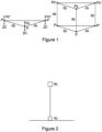
- Figure 1 illustrates schematically two possible 6c sensor configurations.
- a configuration comprising 3x2c sensors, each comprising a hydrophone and a vertically oriented geophone.
- 6xP sensors each comprising a single hydrophone (NB. it is known that vertical particle velocity can be measured by making two separate vertically spaced pressure measurements).
- OBNs Ocean Bottom Nodes
- OBNs are typically battery powered, cableless receivers placed in deep water.
- OBNs can be relatively easy to deploy and remove, and are especially suited for use in relatively congested waters where the deployment of streamers and ocean bottom cables is difficult.
- OBNs are typically deployed and recovered by Remote Operated Vessels (ROVs), using free fall systems and acoustic release to facilitate recovery, or using "nodes on rope” techniques where multiple nodes are attached to a rope with an acoustic release buoy at the end.
- ROVs Remote Operated Vessels
- These approaches are traditionally used to detect data that consists of both P and S waves.
- P waves data
- WO2011/121128 describes a method of providing seismic data (such as marine seismic data).
- a seismic source is actuated at a plurality of source locations.
- a multicomponent seismic measurement is performed at at least one receiver location.
- a reconstructing method is applied to each multicomponent measurement to obtain additional data corresponding to source locations additional to the source locations at which the source was actuated.
- the additional data are output and/or used.
- WO2011/121128 proposes, by way of example, that this approach may be used in the context of OBN / OBS acquisition, i.e. where multicomponent (6c) receiver nodes are located on the seabed and the sources are towed in the water column by a surveying vessel.
- a problem encountered with OBS systems is the interference that occurs between the two types of waves.
- a detector mechanically coupled to the seabed and configured to detect S waves will pick up the effects of P waves propagating in the seabed.
- P waves propagate faster through the subsea formation than do S waves and apparent speed
- not all of the effects can be removed, due to later P arrivals, for example as a result of reflections from different interfaces, ringing in the source signal, and overlapping P and S energy in time due for example to P-S conversion and reflections at or close to the seabed.
- a detector located in the water just above the subsea surface and configured to detect the effects of P waves may be influenced by S waves.
- S waves do not propagate through the water, there will be some conversion of S waves and surface waves / interface waves (Scholte wave; S-wave travelling along the seabed) to P waves at the seabed. It is desirable to remove the effects of such converted S waves from the data collected by the P wave detector and remove the effects of P-waves on the S-detector.
- a method for use in surveying a subsurface region beneath a body of water by detecting S waves propagating through the subsurface region comprises using a first sensor configuration to detect mixed S and P waves on or in the subsurface region, using a second sensor configuration located on or in relatively close proximity to the subsurface region to detect P waves in the water, and using the P waves detected in the water to compensate the detected mixed S and P waves, and thereby attenuate the effects of P waves in the mixed S and P waves.
- the first and second sensor configurations may detect wavefield components comprising one or more of mutually orthogonal particle velocities (Vx, Vy, Vz) or particle accelerations.
- a sensor configuration may detect a particle velocity or particle acceleration using two or more closely spaced hydrophones.
- the step of compensating may comprise scaling a component detected by the second sensor configuration to obtain a scaled component, and subtracting the scaled component from a corresponding component detected by the first sensor configuration.
- the compensation may be applied to wavefield components comprising horizontal particle velocity (Vx and/or Vy) or horizontal particle acceleration.
- a component may be scaled using a scaling factor corresponding to a water to subsurface density ratio (density1/density2).
- the first sensor configuration may comprise a plurality of geophones in mechanical contact with the subsurface and said second sensor configuration comprises a plurality of hydrophones on the seabed or suspended in the water and, optionally geophones or accelerometers, suspended in the water.
- One or both of said first and second sensors may be in mechanical contact with the seabed.
- a second aspect of the present invention there is provided method for use in surveying a subsurface region beneath a body of water by detecting P waves propagating through the body of water.
- the method comprises using the method of the above first aspect of the invention to detect S waves propagating through the subsurface region, compensated in order to attenuate the effects of P waves and applying the compensated S wave to the P waves detected in the water in order to compensate interaction with the former and thereby attenuate the effects of S waves propagating in the subsurface and converted at the water / subsurface interface into P waves propagating in the water or along the seabed.
- the step of applying the compensated S wave to the P waves detected in the water may comprise applying the compensated S wave to the particle velocity Vz, particle acceleration, and/or displacement in the vertical direction. More particularly, the step of applying the compensated S wave to the particle velocity Vz in the vertical direction comprises determining a relationship between the vertical particle velocity and a particle velocity, acceleration, and/or displacement in the horizontal direction, applying that relationship to the compensated S wave data, and subtracting the result from the P wave data.
- the step of applying the compensated S wave to the P waves detected in the water may comprise determining parameters of a digital filtering using the S wave data, and applying the digital filter to the P wave data.
- a third aspect of the present invention there is provided method for use in surveying a subsurface region beneath a body of water by detecting compressional, P, waves propagating through the body of water.
- the method comprises locating one or more sensor systems in the water at or close to the subsurface region, using the or each sensor system to detect P waves in the water, and translating all or a portion of the data representing the detected P waves to a higher level above the subsurface region. This results in the effects of S waves, propagating in the subsurface and converted at the water / subsurface interface into P waves propagating in the water or along the seabed interface, in the translated data being reduced.
- Said higher level may between 1 and 50 meters, preferably 1 to 20 meters, above the level of the sensor system(s).
- the higher level may between one tenth to two apparent horizontal wavelength of the recorded S-wave on the seabed.
- the sensor system may be in mechanical contact with the seabed.
- Said data may comprise one or more of pressure, pressure gradients, vertical particle velocity (Vz), horizontal particle velocity (Vx and/or Vy), vertical particle acceleration, and horizontal particle acceleration.
- a data component at a higher level may be obtained using a corresponding component, detected at or close to the subsurface region by said sensor system, and a first order derivative of that detected component.
- a data component at a higher level may be obtained additionally using one or more higher order derivatives of the detected component.
- Said data component at a higher level may be obtained by applying a Taylor series expansion using a finite and selected number of terms in said expansion.
- a fourth aspect of the present invention there is provided method for use in surveying a subsurface region beneath a body of water by detecting compressional, P, waves propagating through the body of water.
- the method comprises locating one or more sensor systems in the water at or close to the subsurface region, using the or each sensor system to detect P wave data in the water, including at least pressure and pressure gradients or components derived therefrom, translating the P wave data using a combination of pressure, a second order time derivative of pressure, vertical pressure gradient, and second order horizontal pressure gradient or components derived therefrom, and taking spatial derivatives of the translated P wave data to determine particle acceleration or particle velocity data.
- a fifth aspect of the present invention there is provided method for use in surveying a subsurface region beneath a body of water by detecting compressional, P, waves propagating through the body of water.
- the method comprises locating one or more sensor systems in the water at or close to the subsurface region, using the or each sensor system to detect P wave data in the water, including at least pressure and the horizontal pressure gradient, or the horizontal particle velocity or acceleration and the horizontal gradient of the vertical particle velocity or acceleration, and translating the horizontal particle velocity or acceleration of the P wave data using a combination of the horizontal particle velocity(or acceleration) and the horizontal derivatives of the vertical particle velocity or acceleration.
- a sixth aspect of the present invention there is provided method for use in surveying a subsurface region beneath a body of water by detecting compressional, P, waves propagating through the body of water.
- the method comprises locating one or more sensor systems in the water at or close to the subsurface region, using the or each sensor system to detect P wave data in the water, including at least pressure and pressure gradients or components derived thereof, and translating the vertical particle velocity or acceleration of the P wave data using a combination of the vertical particle velocity or acceleration, the time derivative of pressure, and the horizontal derivative of either the horizontal particle velocity or acceleration or the vertical particle velocity or acceleration, including possible phase corrections.
- a seventh aspect of the present invention there is provided method of mapping or imaging a subsurface region beneath a body of water.
- the method comprises detecting S and or P waves according to any one of the above aspects of the invention, and using the resulting data to create a map or image of the subsurface region.
- a sensor system as illustrated in Figure 2 may be used.
- the sensor is located on the seabed and comprises a 4c sensor in mechanical contact with the seabed, and a 6c sensor floating in the water just above the seabed.
- the 6c sensor may have the configuration of either system shown in Figure 1 , or may have any other suitable configuration. It is able to monitor, inter alia, pressure (P) - e.g.
- the 4c sensor monitors four components, namely pressure (P) and three orthogonal components of particle velocity (Vx, Vy and Vz), using a single hydrophone and three orthogonally-oriented geophones. As this sensor is on the seabed, it detects effects due to the presence of P and S waves.
- particle velocity in the seabed (and measured by the 4c sensor) is referred to as the “elastic” particle velocity, whilst that in the water (and measured by the 6c sensor) is referred to as the "acoustic" particle velocity.
- the cleaned data may be further used in wavefield interpolation (in between receivers and/or in between shots) or used directly in PS imaging, that is imaging of converted waves (from P at the source to the reflector and S from the reflector to the receiver) using, for example, wave equation techniques such as reverse time migration (RTM) to enhance the S-wave image and or used directly in full waveform inversion (FWI) to improve mapping of the S-wave properties of the subsurface.
- wave equation techniques such as reverse time migration (RTM) to enhance the S-wave image and or used directly in full waveform inversion (FWI) to improve mapping of the S-wave properties of the subsurface.
- the P-waves and its components measured in the water column, or derived from multicomponent measurements at the seabed, may also be cleaned to remove the effects of S to P converted waves at the seabed by exploiting the data sets including gradients. This may be done either be exploiting the fact that a "pure S-wave dataset" can be derived as described above, and then can be used in a digital filtering process where the structure of the S-data is used as reference structure for what should be filtered out in the P-data set.
- seismic imaging using RTM and full waveform inversion (FWI) of seismic data are merging, and use the recorded data to find the sub-surface model of elastic properties (one or more of the following: shear velocity, P-wave velocity, density, attenuation) that best matches the acquired data.
- the work flow is often iterative in nature: Guess a model, perform forward finite difference modelling, compare modelling results with measured data, use the error/error gradients to change the model at a given location (found from injecting the error wavefield back into the model), and repeat until the errors are within certain acceptance criteria.
- the process is very computer intensive and, in order to limit the computational effort, only acoustic models (acoustic wave equation applies: P-waves and no mode - conversion) are considered.
- the acoustic models / acoustic waves equation is scalar, and can be solved much faster than the full elastic wave equation.
- the additional data may be used to calculate additional data points of the component in question in between the original locations by interpolation, using the extended sampling theorem (involving the data and the horizontal gradients of the data at grid points).
- the extended sampling theorem involving the data and the horizontal gradients of the data at grid points.
- the component we consider here is the particle velocity in the water and not in the seabed, but the normal component (that is Vz, if the seabed is horizontal) is the same at the interface, because this component is continuous through the interface (the horizontal particle velocities Vx and Vy are not continuous).
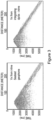
- Figure 3 illustrates data obtained from a field test, comparing horizontal geophone with horizontal particle velocity calculated from the pressure differences (where the vertical axis represents time and the horizontal axis represents distance). The data has been filtered to retain only data between 15- 200Hz (omnidirectional 15Hz geophone used in OBR).
- the left hand panel in the Figures shows time traces of horizontal particle velocity Vx measured by a geophone on the seabed which contains both P and S waves (original PP and mode converted waves PS,SPS, waves).
- the right hand panel in the Figures shows time traces of horizontal particle velocity Vx calculated from pressure difference (two hydrophones in the water on/close to the seabed), and therefore contains only P-waves ( "original PP" and some S to P converted waves).
- the compensation field can be subtracted from the recorded Vx-data on the interface in such a way that the P-wave contribution on the seabed coupled dataset vanishes or reduces to a minimum.
- a similar process can be applied to the Vy data.
- the calibration factor may also be derived directly from the data, using data sections where only P-waves appear (e.g. early arrivals from far offset shots), by an iterative process or search, such as in optimization: Different calibrations factors are tested and the one finally chosen is the one that minimizes the difference between the predicted and measured seabed data.
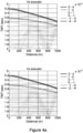
- the vertical axis represents arrival time while the horizontal axis represents horizontal distance along the seabed.
- Vz acoustic and Vz elastic should be similar if the calculation is correct, because the vertical field is continous across the seabed-water interface.
- 'Vx acoustic' and 'Vz acoustic' are particle velocities calculated from the pressure gradients in the water just above the seabed.
- the left hand trace again illustrates Vx in the seabed (Vx elastic, as Figure 4 ), that is the raw data recorded on the horizontal component at the seabed (e.g. using the 4c sensor of Figure 2 ).
- the earliest P-event (direct wave) is marked with an arrow, with other P and S-wave events following. It will be appreciated from the left hand panel that the strongest magnitude events picked up at the seabed are from the early P-waves.
- a constant scaling (density1/density2, where "density1" is the density of the water and “density2" is the density of the seabed) is applied to the Vx acoustic data (e.g.
- Vy diff Vy ⁇ density 1 / density 2 * Vy acoustic .
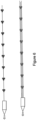
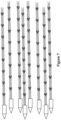
- Figure 6 illustrates two possible approaches. According to the approach illustrated at the top of the Figure, a single "rope" is deployed across the seabed, with multiple nodes in each station having a compact structure (triangle). The second approach shown in Figure 6 involves replacing the single rope of the top approach with three or more densely spaced ropes. These ropes are laid in a single pass, with a spacing of perhaps 2-10m. In order to provide an appropriate receiver grid, multiple parallel ropes are deployed, e.g. with a spacing of 200m or so, as illustrated in Figure 7 .
- the most important component of the P-data that may degrade considerably in value from S-wave imprints is the vertical component; that is, the particle velocity (or particle acceleration, or displacement) in the vertical direction, Vz. This is due to the particular use in subsurface imaging, where the z-component pays a crucial role in the wave field separation (up/down) processes.
- the vertical component that is, the particle velocity (or particle acceleration, or displacement) in the vertical direction, Vz.
- Vz imprint we may subtract the estimated Vz imprint from the recorded Vz to remove the fraction of Vz that is caused by the S-waves.
- Vz-component we can obtain a "cleaned" Vz-component, with reduced imprints, that is more suitable for further P-processing and P-imaging to get better and more efficient subsurface information.
- a first method of predicting the Vz-imprints from the cleaned horizontal components of the S-data (recorded on the seabed) is to apply a theoretical elastic model and/or an efficient numerical elastic model, approximating the local geological conditions and modeling the response of in-coming S-waves with a variety of angle of incidences. Then, from the modeled data, we may find the relationships (or functions) between the Vz imprints and the horizontal particle velocities (or acceleration or displacements) observed on the seabed, and/or selected gradients. Finally we use this function on the cleaned measured S-data and estimate the Vz imprint, and then subtract the estimated imprint on the measured Vz- data.
- the elastic model could be a very simple one, for example a water "half space” over an elastic half space, or a more complex elastic subsea model with a certain spatial distribution of elastic parameters that may be optimized in an iterative process of finding the best values for the Vz imprint calculation.
- the structural similarities of the two data sets are at a minimum (that is, they are most different) when all S-wave imprints have been removed from the Vz- data set.
- the criteria we use to define the optimum filter is how well the result, the filtered Vz data, separates from the S-data set (that is the similarities in the two data sets reduces) and/or how well the residue (the difference between filtered and not-filtered Vz data set) correlates with the S- data set.
- the criteria may be formulated numerically by covariance and correlation expressions or just by inspection with the eye.
- the optimum parameters of the filter may be found by trial and error or by an iterative, automated optimization process.
- dip-filters known in the seismic processing industry as, for example, f-k filters or tau-pi filters, or radon transform filters. These filters are designed to filter out events with certain slopes and curvatures. As mentioned earlier, physics states that the S-imprint can only occur when the apparent phase velocity is lower than a certain limit, and therefore the slope and curvature of the events to be filtered out are higher than a certain limit, a limit that may be found together with the detailed filter parameters and coefficients, described by the process above (iterative / optimization). Finally the filter is used on the Vz data, to remove/attenuate the imprints.
- the described process may also be used on the pressure data and /or x-component as well, in a similar fashion.
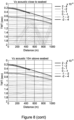
- Figure 8 shows synthetic (modeled) data for Vx acoustic, Vz acoustic, and pressure (P).
- the traces in the top row show the data at the seabed, whilst the traces in the bottom row show the data at a level 10m above the seabed.
- the S wave 'imprints' are indeed greatly reduced at a level 10m above the seabed. It is therefore interesting to calculate the fields (P, Vx, Vy) at a higher level above the seabed, using data acquired close to the seabed, to obtain a result with attenuated S wave imprint.
- k ds or ds/2 (chosen in later example) could be a good choice, but this may be frequency dependant. Possibly the spacing may be dependent upon apparent horizontal wavelength. Even better, k might be found by optimisation methods, i.e. find the k's that minimize S wave imprint. NB. from modelling results it can be seen that, for many models (with soft seabed and low angle S-waves), if we do not have measurements of dv x /dx, we may use dv z /dx instead (with 90 deg phase shift and possibly another scaling factor. Once the cleaned version of Vx and Vz are found (at a new elevation), the wave equation may be used again to find a cleaned version of P.
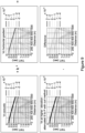
- Figure 9 illustrates in the upper left trace synthetic data for Vx acoustic (i.e. simulating data collected in the water at or very close to the seabed).
- the upper right trace illustrates synthetic data for Vz horizontal gradient at the seabed.
- the Figure illustrates that by multiplying the data in the upper right trace by a scaling factor k, and subtracting the result from the data in the upper left trace, the data shown in the bottom left trace is obtained.
- This result data represents Vx acoustic at a level 8m above the seabed.
- the traces of Figure 10 illustrates a procedure for shifting Vz acoustic to a higher level above the seabed, with the result data, i.e. Vz at a higher level, being shown in the bottom right trace.
- S-Imprints on Vz (using wave equation and dVx/dx) are attenuated.
- the sign is dependent on wave propagation direction and we therefore need to multiply with a sign- function (according to the matlab code below) of the product of the phase shifted Vz-horizontal gradients and the Vx-acoustic horizontal gradient.
- the pressure component is not significantly affected by an S-imprint to start with, but still we can see improvements using the described method. Note that the changes would be clearer if we instead plot the spatial pressure gradients.
- acceleration (ax, az) in the equations, but it could be substituted with the time derivative of particle velocity.
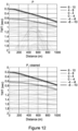
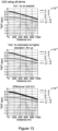
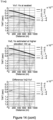
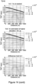
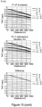
- Figure 13 illustrates a series of plots illustrating the influence on the Vz-component of the P wave data at a higher elevation (row 2) of setting the various terms (non, T1,T2,T3) of Equation 10 to zero.
- the top row of plots are all the same and relate to Vz at the seabed, the second row to Vz at an elevated level (4m), and the bottom row shows the difference between the top row and the second row data.
- Figures 14 and 15 shows the same sets of plots for Vx and Pressure (P) respectively.
- the calibration procedure of the vertical geophone probably needs to be combined also with the P wave data normalized with water or seabed impedance, and run through an optimization procedure involving so call Up-Down separation, unless the data contains single isolated events that can be used directly or in combination with the horizontal components, such as early arrival refracted waves / diving waves from far offset shots.
- Current seabed seismic data is typically obtained using four sensors measuring four components of the seismic wavefield at the seabed, namely pressure and three orthogonal particle displacement components or quantities derived therefrom (such as a time derivative, particle velocity, or particle acceleration). It is proposed here to use additional measurements at each seabed receiver location, (or multiple locations distributed inside a small area that is a fraction of the dominant wavelength) including at least measurements of the horizontal spatial pressure derivatives (and/or quantities derived thereof) and of the horizontal spatial derivatives of the displacement vectors (or its time derivatives) of the seabed, and to use this combined data set to enhance seismic data quality, separate elastic wave fields, and improve subsurface imaging.
- One application is to exploit the diversity in this type of recorded data for single or multiple seismic shots to improve the calibration of each individual receiver component with respect to magnitude and phase and/or orientation and/or vector fidelity and/or position and/or recorder clock drift, using a specified workflow and optimization / calibration routine.
- the discrete spatial sampling theorems and reciprocity principles that apply to source and receiver arrays may be applied in order to interpolate additional source and receiver locations.
- the collected cleaned S and P wave data obtained from a given array of OBNs
Landscapes
- Life Sciences & Earth Sciences (AREA)
- Physics & Mathematics (AREA)
- Engineering & Computer Science (AREA)
- Remote Sensing (AREA)
- Acoustics & Sound (AREA)
- Environmental & Geological Engineering (AREA)
- Geology (AREA)
- General Life Sciences & Earth Sciences (AREA)
- General Physics & Mathematics (AREA)
- Geophysics (AREA)
- Oceanography (AREA)
- Geophysics And Detection Of Objects (AREA)
Applications Claiming Priority (3)
| Application Number | Priority Date | Filing Date | Title |
|---|---|---|---|
| GB1408083.2A GB2525896B (en) | 2014-05-07 | 2014-05-07 | P/S wave measurement and compensation |
| PCT/EP2015/059962 WO2015169860A2 (fr) | 2014-05-07 | 2015-05-06 | Mesure d'ondes p/s et compensation |
| EP15722986.5A EP3140678B1 (fr) | 2014-05-07 | 2015-05-06 | Mesure d'ondes p/s et compensation |
Related Parent Applications (2)
| Application Number | Title | Priority Date | Filing Date |
|---|---|---|---|
| EP15722986.5A Division EP3140678B1 (fr) | 2014-05-07 | 2015-05-06 | Mesure d'ondes p/s et compensation |
| EP15722986.5A Division-Into EP3140678B1 (fr) | 2014-05-07 | 2015-05-06 | Mesure d'ondes p/s et compensation |
Publications (2)
| Publication Number | Publication Date |
|---|---|
| EP4184221A2 true EP4184221A2 (fr) | 2023-05-24 |
| EP4184221A3 EP4184221A3 (fr) | 2023-07-19 |
Family
ID=50980748
Family Applications (2)
| Application Number | Title | Priority Date | Filing Date |
|---|---|---|---|
| EP15722986.5A Active EP3140678B1 (fr) | 2014-05-07 | 2015-05-06 | Mesure d'ondes p/s et compensation |
| EP22205385.2A Pending EP4184221A3 (fr) | 2014-05-07 | 2015-05-06 | Mesure et compensation d'onde p/s |
Family Applications Before (1)
| Application Number | Title | Priority Date | Filing Date |
|---|---|---|---|
| EP15722986.5A Active EP3140678B1 (fr) | 2014-05-07 | 2015-05-06 | Mesure d'ondes p/s et compensation |
Country Status (6)
| Country | Link |
|---|---|
| US (2) | US10365388B2 (fr) |
| EP (2) | EP3140678B1 (fr) |
| BR (2) | BR112016025812B1 (fr) |
| CA (2) | CA2947966C (fr) |
| GB (2) | GB2525896B (fr) |
| WO (1) | WO2015169860A2 (fr) |
Families Citing this family (6)
| Publication number | Priority date | Publication date | Assignee | Title |
|---|---|---|---|---|
| US10345463B2 (en) * | 2014-02-21 | 2019-07-09 | Ion Geophysical Corporation | Methods and systems for using known source events in seismic data processing |
| US10768322B2 (en) * | 2015-08-27 | 2020-09-08 | Pgs Geophysical As | Analogous processing of modeled and measured marine survey data |
| US10261203B2 (en) * | 2016-06-24 | 2019-04-16 | Pgs Geophysical As | Migrating a horizontal component of a wavefield |
| US11435491B2 (en) * | 2019-04-15 | 2022-09-06 | Saudi Arabian Oil Company | Wave velocity determination for seismic imaging |
| CN112147695B (zh) * | 2020-09-30 | 2022-09-16 | 长安大学 | 一种海底节点检波器水下姿态定向方法 |
| CN112799133B (zh) * | 2020-12-30 | 2022-06-28 | 长安大学 | 用于交错网格模拟地震数据的波场分离与时移校正方法 |
Citations (1)
| Publication number | Priority date | Publication date | Assignee | Title |
|---|---|---|---|---|
| WO2011121128A2 (fr) | 2010-04-01 | 2011-10-06 | Statoil Petroleum As | Procédé d'obtention de données séismiques |
Family Cites Families (15)
| Publication number | Priority date | Publication date | Assignee | Title |
|---|---|---|---|---|
| US2927300A (en) * | 1955-06-20 | 1960-03-01 | California Research Corp | Cancellation of seismic surface noise |
| US6879546B2 (en) * | 2002-02-14 | 2005-04-12 | Westerngeco, L.L.C. | Gel-filled seismic streamer cable |
| US7791980B2 (en) * | 2004-05-21 | 2010-09-07 | Westerngeco L.L.C. | Interpolation and extrapolation method for seismic recordings |
| GB2414299B (en) * | 2004-05-21 | 2006-08-09 | Westerngeco Ltd | Interpolation and extrapolation method for seismic recordings |
| US20060193203A1 (en) * | 2005-02-16 | 2006-08-31 | Tenghamn Stig R L | Apparatus for attenuating noise in marine seismic streamers |
| US7468932B2 (en) * | 2005-05-13 | 2008-12-23 | Pgs Americas, Inc. | System for noise attenuation in marine seismic streamers |
| US7433265B2 (en) * | 2005-10-04 | 2008-10-07 | Fairfield Industries, Inc. | Converted wave energy removal from seismic data |
| US8077543B2 (en) * | 2007-04-17 | 2011-12-13 | Dirk-Jan Van Manen | Mitigation of noise in marine multicomponent seismic data through the relationship between wavefield components at the free surface |
| US8379482B1 (en) * | 2009-01-13 | 2013-02-19 | Exxonmobil Upstream Research Company | Using seismic attributes for data alignment and seismic inversion in joint PP/PS seismic analysis |
| US20130088939A1 (en) * | 2011-10-10 | 2013-04-11 | Pascal Edme | Wavefield separation using a gradient sensor |
| FR2985039B1 (fr) * | 2011-12-21 | 2015-07-03 | Cggveritas Services Sa | Noeud sous-marin couple avec l'eau pour des etudes sismiques |
| AU2012369973B2 (en) * | 2012-02-14 | 2015-10-29 | Halliburton Energy Services, Inc. | Shear wave source for VSP and surface seismic exploration |
| RU2015123286A (ru) * | 2012-11-20 | 2017-01-10 | Сточастик Симюлэйшн Лимитед | Способ и система для снятия характеристик подземных пластов |
| CA2948064A1 (fr) * | 2014-05-07 | 2015-11-12 | Statoil Petroleum As | Systeme capteur pour enregistrements sismiques |
| GB2548555B (en) * | 2016-03-16 | 2021-10-20 | Equinor Energy As | A method of redatuming geophysical data |
-
2014
- 2014-05-07 GB GB1408083.2A patent/GB2525896B/en active Active
- 2014-05-07 GB GB1619004.3A patent/GB2546145B/en active Active
-
2015
- 2015-05-06 CA CA2947966A patent/CA2947966C/fr active Active
- 2015-05-06 EP EP15722986.5A patent/EP3140678B1/fr active Active
- 2015-05-06 WO PCT/EP2015/059962 patent/WO2015169860A2/fr active Application Filing
- 2015-05-06 BR BR112016025812-6A patent/BR112016025812B1/pt active IP Right Grant
- 2015-05-06 US US15/309,043 patent/US10365388B2/en active Active
- 2015-05-06 EP EP22205385.2A patent/EP4184221A3/fr active Pending
- 2015-05-06 CA CA3224766A patent/CA3224766A1/fr active Pending
- 2015-05-06 BR BR122020016505-7A patent/BR122020016505B1/pt active IP Right Grant
-
2019
- 2019-04-24 US US16/393,681 patent/US11733418B2/en active Active
Patent Citations (1)
| Publication number | Priority date | Publication date | Assignee | Title |
|---|---|---|---|---|
| WO2011121128A2 (fr) | 2010-04-01 | 2011-10-06 | Statoil Petroleum As | Procédé d'obtention de données séismiques |
Also Published As
| Publication number | Publication date |
|---|---|
| EP4184221A3 (fr) | 2023-07-19 |
| GB2546145A (en) | 2017-07-12 |
| GB201408083D0 (en) | 2014-06-18 |
| GB2525896B (en) | 2017-01-11 |
| BR122020016505B1 (pt) | 2022-11-29 |
| EP3140678C0 (fr) | 2023-07-05 |
| GB2546145B (en) | 2018-03-14 |
| GB2525896A (en) | 2015-11-11 |
| US10365388B2 (en) | 2019-07-30 |
| BR122020016505A8 (pt) | 2022-11-01 |
| US20190250297A1 (en) | 2019-08-15 |
| BR112016025812A8 (fr) | 2022-11-08 |
| BR112016025812A2 (pt) | 2017-08-15 |
| CA3224766A1 (fr) | 2015-11-12 |
| US11733418B2 (en) | 2023-08-22 |
| BR112016025812B1 (pt) | 2023-04-25 |
| EP3140678A2 (fr) | 2017-03-15 |
| US20170075008A1 (en) | 2017-03-16 |
| CA2947966A1 (fr) | 2015-11-12 |
| BR122020016505A2 (fr) | 2017-08-15 |
| CA2947966C (fr) | 2024-02-13 |
| WO2015169860A2 (fr) | 2015-11-12 |
| WO2015169860A3 (fr) | 2015-12-30 |
| EP3140678B1 (fr) | 2023-07-05 |
Similar Documents
| Publication | Publication Date | Title |
|---|---|---|
| US11733418B2 (en) | P/S wave measurement and compensation | |
| US7710821B2 (en) | Multiple attenuation method | |
| AU2005282945B2 (en) | System for the attenuation of water bottom multiples in seismic data recorded by pressure sensors and particle motion sensors | |
| EP2930541B1 (fr) | Séparation de signaux sismiques produits par des sources sismiques interférentes | |
| CN103245969B (zh) | 用于在震源虚反射去除之后确定源特征波形的方法和系统 | |
| AU2008201434B2 (en) | Method for prediction of surface related multiples from marine towed dual sensor seismic streamer data | |
| AU2014201491B2 (en) | Systems and methods for frequency-domain filtering and space-time domain discrimination of seismic data | |
| US9310503B2 (en) | Methods to process seismic data contaminated by coherent energy radiated from more than one source | |
| EP2249182B1 (fr) | Procédé de calcul d'attributs sismiques à partir de signaux sismiques | |
| NO339072B1 (no) | Hurtig 3-D-overflatemultippel-prediksjon | |
| EP2187240B1 (fr) | Procédé de combinaison optimum de pression et capteurs de mouvement de particules pour la dispersion en 3D de flûtes sismiques matines à double capteur | |
| CN1997914A (zh) | 三维反虚反射 | |
| US11092708B2 (en) | Processes and systems to enhance illumination and resolution of seismic images using multiple reflected wavefields | |
| AU2015200774A1 (en) | Methods and systems for quantifying coherency and constraining coherency-based separation in simultaneous shooting acquisition | |
| WO2021071947A1 (fr) | Détermination des propriétés d'une formation souterraine à l'aide d'une équation d'onde acoustique ayant un paramétrage de réflectivité | |
| EP2299296A1 (fr) | Procédé de combinaison de signaux de pression et capteurs de mouvement de particules dans des flûtes sismiques marines | |
| US11391857B2 (en) | Methods and systems for attenuating residual acoustic energy in seismic data | |
| US11385373B2 (en) | Method for determining sensor depths and quality control of sensor depths for seismic data processing | |
| Vaddineni et al. | Seismic evidence for deep hydrothermal circulation and faulting at slow spreading Mid-Atlantic Ridge |
Legal Events
| Date | Code | Title | Description |
|---|---|---|---|
| PUAI | Public reference made under article 153(3) epc to a published international application that has entered the european phase |
Free format text: ORIGINAL CODE: 0009012 |
|
| STAA | Information on the status of an ep patent application or granted ep patent |
Free format text: STATUS: REQUEST FOR EXAMINATION WAS MADE |
|
| 17P | Request for examination filed |
Effective date: 20221103 |
|
| AC | Divisional application: reference to earlier application |
Ref document number: 3140678 Country of ref document: EP Kind code of ref document: P |
|
| AK | Designated contracting states |
Kind code of ref document: A2 Designated state(s): AL AT BE BG CH CY CZ DE DK EE ES FI FR GB GR HR HU IE IS IT LI LT LU LV MC MK MT NL NO PL PT RO RS SE SI SK SM TR |
|
| PUAL | Search report despatched |
Free format text: ORIGINAL CODE: 0009013 |
|
| AK | Designated contracting states |
Kind code of ref document: A3 Designated state(s): AL AT BE BG CH CY CZ DE DK EE ES FI FR GB GR HR HU IE IS IT LI LT LU LV MC MK MT NL NO PL PT RO RS SE SI SK SM TR |
|
| RIC1 | Information provided on ipc code assigned before grant |
Ipc: G01V 1/36 20060101AFI20230613BHEP |
|
| STAA | Information on the status of an ep patent application or granted ep patent |
Free format text: STATUS: EXAMINATION IS IN PROGRESS |
|
| 17Q | First examination report despatched |
Effective date: 20240320 |