EP4184215A1 - Laser tracking device - Google Patents
Laser tracking device Download PDFInfo
- Publication number
- EP4184215A1 EP4184215A1 EP21910031.0A EP21910031A EP4184215A1 EP 4184215 A1 EP4184215 A1 EP 4184215A1 EP 21910031 A EP21910031 A EP 21910031A EP 4184215 A1 EP4184215 A1 EP 4184215A1
- Authority
- EP
- European Patent Office
- Prior art keywords
- light
- telescope
- moving body
- laser tracking
- emission
- Prior art date
- Legal status (The legal status is an assumption and is not a legal conclusion. Google has not performed a legal analysis and makes no representation as to the accuracy of the status listed.)
- Pending
Links
Images











Classifications
-
- G—PHYSICS
- G01—MEASURING; TESTING
- G01S—RADIO DIRECTION-FINDING; RADIO NAVIGATION; DETERMINING DISTANCE OR VELOCITY BY USE OF RADIO WAVES; LOCATING OR PRESENCE-DETECTING BY USE OF THE REFLECTION OR RERADIATION OF RADIO WAVES; ANALOGOUS ARRANGEMENTS USING OTHER WAVES
- G01S17/00—Systems using the reflection or reradiation of electromagnetic waves other than radio waves, e.g. lidar systems
- G01S17/66—Tracking systems using electromagnetic waves other than radio waves
-
- G—PHYSICS
- G01—MEASURING; TESTING
- G01S—RADIO DIRECTION-FINDING; RADIO NAVIGATION; DETERMINING DISTANCE OR VELOCITY BY USE OF RADIO WAVES; LOCATING OR PRESENCE-DETECTING BY USE OF THE REFLECTION OR RERADIATION OF RADIO WAVES; ANALOGOUS ARRANGEMENTS USING OTHER WAVES
- G01S7/00—Details of systems according to groups G01S13/00, G01S15/00, G01S17/00
- G01S7/48—Details of systems according to groups G01S13/00, G01S15/00, G01S17/00 of systems according to group G01S17/00
- G01S7/481—Constructional features, e.g. arrangements of optical elements
- G01S7/4814—Constructional features, e.g. arrangements of optical elements of transmitters alone
-
- G—PHYSICS
- G01—MEASURING; TESTING
- G01S—RADIO DIRECTION-FINDING; RADIO NAVIGATION; DETERMINING DISTANCE OR VELOCITY BY USE OF RADIO WAVES; LOCATING OR PRESENCE-DETECTING BY USE OF THE REFLECTION OR RERADIATION OF RADIO WAVES; ANALOGOUS ARRANGEMENTS USING OTHER WAVES
- G01S7/00—Details of systems according to groups G01S13/00, G01S15/00, G01S17/00
- G01S7/48—Details of systems according to groups G01S13/00, G01S15/00, G01S17/00 of systems according to group G01S17/00
- G01S7/481—Constructional features, e.g. arrangements of optical elements
- G01S7/4816—Constructional features, e.g. arrangements of optical elements of receivers alone
-
- G—PHYSICS
- G01—MEASURING; TESTING
- G01S—RADIO DIRECTION-FINDING; RADIO NAVIGATION; DETERMINING DISTANCE OR VELOCITY BY USE OF RADIO WAVES; LOCATING OR PRESENCE-DETECTING BY USE OF THE REFLECTION OR RERADIATION OF RADIO WAVES; ANALOGOUS ARRANGEMENTS USING OTHER WAVES
- G01S7/00—Details of systems according to groups G01S13/00, G01S15/00, G01S17/00
- G01S7/48—Details of systems according to groups G01S13/00, G01S15/00, G01S17/00 of systems according to group G01S17/00
- G01S7/481—Constructional features, e.g. arrangements of optical elements
- G01S7/4817—Constructional features, e.g. arrangements of optical elements relating to scanning
-
- G—PHYSICS
- G01—MEASURING; TESTING
- G01S—RADIO DIRECTION-FINDING; RADIO NAVIGATION; DETERMINING DISTANCE OR VELOCITY BY USE OF RADIO WAVES; LOCATING OR PRESENCE-DETECTING BY USE OF THE REFLECTION OR RERADIATION OF RADIO WAVES; ANALOGOUS ARRANGEMENTS USING OTHER WAVES
- G01S7/00—Details of systems according to groups G01S13/00, G01S15/00, G01S17/00
- G01S7/48—Details of systems according to groups G01S13/00, G01S15/00, G01S17/00 of systems according to group G01S17/00
- G01S7/497—Means for monitoring or calibrating
-
- G—PHYSICS
- G02—OPTICS
- G02B—OPTICAL ELEMENTS, SYSTEMS OR APPARATUS
- G02B26/00—Optical devices or arrangements for the control of light using movable or deformable optical elements
- G02B26/08—Optical devices or arrangements for the control of light using movable or deformable optical elements for controlling the direction of light
- G02B26/0816—Optical devices or arrangements for the control of light using movable or deformable optical elements for controlling the direction of light by means of one or more reflecting elements
-
- G—PHYSICS
- G01—MEASURING; TESTING
- G01S—RADIO DIRECTION-FINDING; RADIO NAVIGATION; DETERMINING DISTANCE OR VELOCITY BY USE OF RADIO WAVES; LOCATING OR PRESENCE-DETECTING BY USE OF THE REFLECTION OR RERADIATION OF RADIO WAVES; ANALOGOUS ARRANGEMENTS USING OTHER WAVES
- G01S17/00—Systems using the reflection or reradiation of electromagnetic waves other than radio waves, e.g. lidar systems
- G01S17/02—Systems using the reflection of electromagnetic waves other than radio waves
- G01S17/06—Systems determining position data of a target
- G01S17/08—Systems determining position data of a target for measuring distance only
- G01S17/10—Systems determining position data of a target for measuring distance only using transmission of interrupted, pulse-modulated waves
Definitions
- the present invention relates to laser tracking devices.
- a laser tracking device that use lasers to observe moving bodies that move in space, such as satellites, space debris, and the like.
- a laser tracking device When tracking a moving body, a laser tracking device often waits for the moving body being detected in a state in which the optical axis of a telescope is directed to a given position on a predicted orbit of the moving body. After detecting the moving body, the laser tracking device moves the direction of the optical axis of the telescope in accordance with the moving velocity of the moving body.
- large aperture telescopes are used to observe the positions of moving bodies with high precision. It is however difficult to quickly modify the optical axis direction of a large aperture telescope.
- a laser tracking device requires controlling the optical axis direction of the telescope with high precision to observe the position of the moving body with improved precision. It is however difficult to control the optical axis direction of the telescope with high precision over a wide range.
- the inventors have conceived of using a first optical system that modifies the optical axis direction with relatively low precision and a second optical system that modifies the optical axis direction with relatively high precision.
- Patent Literature 1 Japanese Patent Gazette No. 3382530 discloses a size-reduced optical imaging device with high sensitivity which uses two optical systems.
- This optical imaging device which is mounted on a flying body such as an aircraft or a satellite to image the earth's surface, includes an objective flat scanning mirror and a compensating flat scanning mirror.
- the objective flat scanning mirror is operated to cause the optical axis for light reception from the earth's surface to scan the earth's surface.
- the compensating flat scanning mirror reflects the light wave reflected by the objective flat scanning mirror towards an imaging device such that a still image is imaged in the imaging device while one image of the earth's surface is acquired.
- Patent Literature 1 Japanese Patent Gazette No. 3382530
- one of objectives is to provide a laser tracking device that can track a moving body with high precision.
- Other objectives would be understood from the below-given recitation and the description of embodiments.
- a laser tracking device for achieving the above-described objective includes an adjustment device, a telescope, and a drive device.
- the adjustment device modifies the emission direction of first light wave.
- the telescope emits the first light wave in the emission direction modified by the adjustment device.
- the drive device rotates the telescope based on a predicted path of the moving body.
- the adjustment device provides more precision in modifying the emission direction of the first light wave than in the drive device rotating the telescope. Further, the adjustment device modifies the emission direction to offset the modification of the emission direction caused by the rotation of the telescope from a time when a tracking start condition is satisfied until the moving body is detected.
- the above-described embodiment allows the laser tracking device to track the moving body with improved precision.
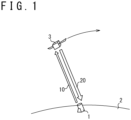
- a laser tracking device 1 is installed, for example, on the ground 2 and configured to detect the position of a moving body 3. More specifically, the laser tracking device 1 emits the output light 10 such as laser light to the moving body 3 and detects the position of the moving body 3 with high precision by receiving reflected light 20 from the moving body 3. After detecting the position of the moving body 3, the laser tracking device 1 is configured to track the moving body 3 by modifying the emission direction of the output light 10 to follow the movement of the moving body 3. It is noted that the moving body 3 may include any moving object, for example, an object or flying body that circles around the earth, such as a satellite and a space debris.
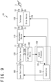
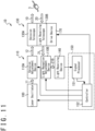
- the laser tracking device 1 includes a laser oscillator 100, an adjustment device 110, a splitter device 120, a telescope 130, a light receiving device 140, a processing device 150, and a drive device 170.
- the drive device 170 moves the telescope 130 based on a predicted path of the moving body 3.
- the drive device 170 rotates the telescope 130 based on the predicted path of the moving body 3.
- the adjustment device 110 adjusts the emission direction of the output light 10 to detect the position of the moving body 3. This allows the laser tracking device 1 to, when detecting the moving body 3, track the moving body 3 without abruptly changing the speed at which the telescope 130 is rotated.
- the splitter device 120 allows the laser tracking device 1 to achieve both emission of the output light 10 and reception of the reflected light 20 by using the single telescope 130. It is noted that the adjustment device 110 provides more precision in controlling the emission direction of the output light 10 than in the drive device 170 controlling the emission direction of the output light 10 by rotating the telescope 130.
- initial light 11 emitted by the laser oscillator 100 is outputted from the telescope 130 via the adjustment device 110 and the splitter device 120.
- the laser oscillator 100 outputs the initial light 11, such as laser light, to the adjustment device 110.
- the laser oscillator 100 receives an emission signal generated by the processing device 150 and emits the initial light 11.
- the initial light 11 may be pulse laser light, for example.
- the adjustment device 110 is configured to adjust the travel direction of the initial light 11 and output the same as adjusted light 12. By adjusting the travel direction of the initial light 11 by the adjustment device 110, the emission direction of the output light 10 is modified around the axial direction of the telescope 130.
- the adjustment device 110 includes a rotatably-disposed optical element 111 such as a mirror, and an actuator 112 that rotates the optical element 111.
- the optical element 111 reflects the initial light 11 to change the travel direction of the initial light 11.
- the actuator 112 is configured to rotate the optical element 111 with high resolution.
- the actuator 112 is configured to adjust the rotation angle of the optical element 111, for example, in units of 10 microradians ( ⁇ rad).
- the actuator 112 includes a piezo element and the adjustment device 110 includes a piezo mirror.
- the rotation axis of the optical element 111 may be arbitrarily selected.
- the optical element 111 may have one rotation axis or two rotation axes. It is noted that the actuator 112 is driven based on a control signal generated by the processing device 150.
- the splitter device 120 is configured to guide light wave from the laser oscillator 100, such as the adjusted light 12, into the telescope 130.
- the splitter device 120 is also configured to guide acquired light 21 received from the telescope 130 to the light receiving device 140.
- the splitter device 120 includes a half mirror and directly guides the adjusted light 12 into the telescope 130 by letting the adjusted light 12 pass therethrough while reflecting the acquired light 21 as splitted light 22 to directly guide the splitted light 22 into the light receiving device 140.
- the telescope 130 may be configured, for example, as a Coude reflecting telescope.
- the telescope 130 includes a tube 131 and a plurality of mirrors, for example, a first mirror 132, a second mirror 133, a third mirror 134, and a fourth mirror 135.
- the adjusted light 12 is reflected in turn by the fourth mirror 135, the third mirror 134, the second mirror 133, and the first mirror 132 and outputted as the output light 10 from an aperture disposed at one end of the tube 131.
- the tube 131 is cylindrically shaped and configured to output the output light 10 from the one end thereof.
- the tube 131 also includes an aperture 139 at the side face thereof through which the adjusted light 12 is introduced.
- the fourth mirror 135 is configured to guide the adjusted light 12 outputted from the splitter device 120 into the tube 131 through the aperture 139 of the tube 131.
- the fourth mirror 135 includes a plurality of mirrors and is configured to guide the adjusted light 12 outputted from the splitter device 120 into the tube 131 regardless of the axial direction of the tube 131.
- the third mirror 134, the second mirror 133, and the first mirror 132 are arranged to output the output light 10 from an end of the tube 131. More specifically, the first mirror 132 is disposed at the end of the tube 131 in the opposite direction of the direction in which the output light 10 is outputted. The first mirror 132 has a concave reflecting surface. The second mirror 133 is disposed at the focal position of the first mirror 132. The second mirror 133 has a convex reflecting surface. The third mirror 134 is arranged to reflect the adjusted light 12 reflected by the fourth mirror 135 towards the second mirror 133. The adjusted light 12 is reflected in the tube 131 by the third mirror 134, the second mirror 133, and the first mirror 132 and outputted as the output light 10 from one end of the tube 131.
- any telescope structures may be selected for the telescope 130, not limited to the Coude reflecting telescope structure.
- a Nasmyth reflecting telescope structure may be selected for the telescope 130.
- the drive device 170 may rotate the laser oscillator 100, the adjustment device 110, the splitter device 120, and the light receiving device 140 in accordance with the rotation of the telescope 130 when the emission direction of the output light 10 is rotated to a direction in the horizontal plane.
- a Galilean telescope structure may be selected for the telescope 130.
- the drive device 170 may rotate the laser oscillator 100, the adjustment device 110, the splitter device 120, and the light receiving device 140 in accordance with the rotation of the telescope 130.
- the light wave outputted by the laser oscillator 100 is outputted from one end of the telescope 130.
- the reflected light 20 from the moving body 3 is received by the light receiving device 140 via the telescope 130 and the splitter device 120.
- the telescope 130 outputs to the splitter device 120 the reflected light 20 that reaches the end of the telescope 130 as acquired light 21. More specifically, the reflected light 20 is reflected by the first mirror 132, the second mirror 133, and the third mirror 134 and outputted from the aperture 139 of the tube 131. The reflected light 20 outputted from the tube 131 is reflected by the fourth mirror 135 and guided to the splitter device 120.
- the fourth mirror includes a plurality of mirrors and is configured to guide the reflected light 20 outputted from the aperture 139 of the tube 131 to the splitter device 120, regardless of the direction in which the axial direction of the tube 131 is directed.
- the splitter device 120 is configured to guide the acquired light 21 to the light receiving device 140 as splitted light 22.
- the splitter device 120 includes a half mirror and reflects the acquired light 21 as the splitted light 22 to a direction different from the light axis direction of the adjusted light 12.
- the splitter device 120 is configured to guide the adjusted light 12 from the laser oscillator 100 to the telescope 130 and also guide the acquired light 21 from the telescope 130 to the light receiving device 140.
- the light wave received by the telescope 130 is guided to the light receiving device 140.
- the light receiving device 140 measures, based on the splitted light 22 received from the splitter device 120, a photon count of the splitted light 22, for example, the number of photons included in the splitted light 22.
- the measured photon count includes the number of photons corresponding to the reflected light 20 from the moving body 3.
- the light receiving device 140 transmits the measured photon count to the signal processor 151 of the processing device 150.
- the photon count may include the time of the light reception.
- the light receiving device 140 may be a photometer, for example.
- the processing device 150 includes a signal processor 151 and a controller 152.
- the processing device 150 performs various processes to control the laser tracking device 1.
- the processing device 150 is a computer that includes a central processor unit (CPU), a storage device, and other devices, for example.
- the processing device 150 may include one or more computers.
- the signal processor 151 detects a moving body 3 based on the photon count from the light receiving device 140. The signal processor 151 determines whether the splitted light 22 incudes the reflected light 20 from the moving body 3 based on changes in the photon count. When the splitted light 22 incudes the reflected light 20 from the moving body 3, the signal processor 151 outputs to the controller 152 a detection signal that indicates that the moving body 3 is detected.
- the controller 152 controls the laser oscillator 100, the adjustment device 110, and the drive device 170.
- the controller 152 controls the drive device 170 based on the predicted path of the moving body 3 to rotate the telescope 130.
- the controller 152 further specifies the timing at which the laser oscillator 100 is to emit the initial light 11.
- the controller 152 further controls the adjustment device 110 based on the detection signal from the signal processor 151 such that the output light 10 is emitted to the moving body 3.
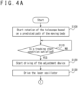
- the laser tracking device 1 tracks the moving body 3 through the procedure shown in FIGs. 4A and 4B .
- the laser tracking device 1 manually or automatically starts the procedure shown in FIGs. 4A and 4B .
- the controller 152 controls the drive device 170 based on a predicted path of the moving body 3 to move the telescope 130. More specifically, the controller 152 acquires the predicted path of the moving body 3 from an external entity. The predicted path represents the path along which the moving body 3 will move and the positions of the moving body 3 at predetermined instances of time.
- the controller 152 generates, based on the predicted path, a signal that controls the drive device 170 such that the axis of the telescope 130 is directed towards a predicted position of the moving body 3.
- the drive device 170 rotates the telescope 130 such that the axis of the telescope 130 is directed towards the predicted position of the moving body 3.
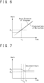
- the controller 152 rotates the telescope 130 such that the angle ⁇ between the horizontal plane 5 and the axis direction 6 of the telescope 130 is equal to the angle between the horizontal plane 5 and the predicted direction from the laser tracking device 1 to the moving body 3. More specifically, as shown in FIG. 6 , the controller 152 accelerates the rotation speed of the telescope 130 to the speed corresponding to the travel speed of the moving body 3 and rotates the telescope 130 to move the axis direction 6 of the telescope 130 along the predicted path of the moving body 3 at step S100.
- the controller 152 determines whether a tracking start condition is satisfied.
- the tracking start condition may include any conditions, such as the instance of time, the position of the moving body 3, the error between the rotation speed of the telescope 130 and the predicted path of the moving body 3, and the like.
- the controller 152 determines that the tracking start condition is satisfied when the tracking start time has been reached.
- the controller 152 performs the process of step S120.
- the controller 152 repeats step S 110 until the tracking start condition is satisfied. For example, an assumption is made that the controller 152 starts the tracking at a tracking start time ti. In this case, as shown in FIG.
- the controller 152 rotates the telescope 130 at the tracking start time ti such that the axis direction of the telescope 130 is at a first angle ⁇ 1 which is the same as the direction of the moving body 3. Further, the controller 152 rotates the telescope 130 such that the rotation speed of the telescope 130 reaches the speed corresponding to a predicted speed of the moving body 3 at the tracking start time ti.
- the controller 152 drives the adjustment device 110 to adjust the emission direction of the output light 10. For example, when the tracking start condition is satisfied, the controller 152 drives the adjustment device 110 such that the emission direction of the output light 10 is kept at a predetermined angle ⁇ . More specifically, as shown in FIG. 7 , the controller 152 controls, before the tracking start time ti at which the tracking start condition is satisfied, the adjustment device 110 such that the adjustment angle with which the adjustment device 110 adjusts the emission direction of the output light 10 is a second angle ⁇ 2 .
- the second angle ⁇ 2 is the maximum value of the adjustment angle adjustable by the adjustment device 110.
- the controller 152 rotates the adjustment device 110 to a direction to reduce the angle ⁇ .
- the actuator 112 of the adjustment device 110 rotates the optical element 111 based on the control signal from the controller 152 to offset the modification in the emission direction of the output light 10 caused by the rotation of the telescope 130. Accordingly, as shown in FIG. 8 , the emission direction of the output light 10 is kept unchanged for a predetermined time duration after the tracking start time ti.
- the controller 152 starts emission of the initial light 11 by driving the laser oscillator 100.
- the initial light 11 is for example, pulse laser light with a specified wavelength.
- the output light 10 is emitted in a specified direction, more specifically, to the angle of the sum of ⁇ 1 and ⁇ 2 for the predetermined time after the tracking start time ti.
- the controller 152 determines whether the moving body 3 is detected. More specifically, the light receiving device 140 measures a photon count based on the light wave received by the telescope 130. The controller 152 determines, based on the measured photon count, whether the light wave received by the telescope 130 includes the reflected light 20 from the moving body 3. The controller 152 performs the process of step S150 when determining that the light wave received by the telescope 130 does not include the reflected light 20. The controller 152 performs the process of step S160 when determining that the light wave received by the telescope 130 includes the reflected light 20.
- the controller 152 determines whether a predetermined time has elapsed after the tracking start condition is satisfied. When the predetermined time has not elapsed after the tracking start time ti, the controller 152 returns to the process of step S140 to continue the detection of the moving body 3. When the predetermined time has elapsed after the tracking start time ti, the controller 152 determines that it is impossible to detect the moving body 3 and terminates the tracking process, stopping the laser oscillator 100, the drive device 170, and the like. For example, as shown in FIG.
- the predetermined time is the time until the adjustment angle by the adjustment device 110 reaches a third angle ⁇ 3 , that is, the time between the tracking start time ti and a tracking limit time t 2 .
- the third angle ⁇ 3 is, for example, the minimum value of the adjustment angle adjustable by the adjustment device 110.
- the controller 152 calculates the error between the position of the moving body 3 and the predicted path of the moving body 3 based on the time when the moving body 3 is detected. For example, the controller 152 calculates the direction of the moving body 3 with respect to the laser tracking device 1 based on the emission direction of the output light 10 at the time when the moving body 3 is detected. Further, the controller 152 calculates the distance from the laser tracking device 1 to the moving body 3 based on the time when the moving body 3 is detected (for example, the time when the reflected light 20 is received) and the time when the output light 10 is emitted. This allows the controller 152 to calculate the precise position of the moving body 3. Further, the controller 152 calculates the error between the predicted path of the moving body 3 and the current position of the moving body 3 based on the time when the reflected light 20 is received or the time when the output light 10 is emitted.
- the controller 152 drives the adjustment device 110 based on the calculated error. More specifically, the controller 152 calculates an adjustment angle of the adjustment device 110 based on the calculated error such that the emission direction of the output light 10 is directed towards the moving body 3 and sets the adjustment device 110 to the calculated adjustment angle. As shown in FIG. 7 , after the detection time t 3 when the moving body 3 is detected, the controller 152 maintains the adjustment error of the adjustment device 110 in accordance with the calculated adjustment error. The drive device 170 rotates the telescope 130 along the predicted path of the moving body 3, and the adjustment device 110 is set to the adjustment angle in accordance with the error. As such, as shown in FIG. 8 , the controller 152 drives the telescope 130 along the predicted path of the moving body 3 to track the moving body 3.
- the controller 152 determines whether an end condition to terminate the tracking of the moving body 3 is satisfied. When determining the end condition is not satisfied, the controller 152 repeats the process of step S180 until the end condition is satisfied. When determining that the end condition is satisfied, the controller 152 stops the tracking of the moving body 3, stopping respective devices of the laser tracking device 1, including the laser oscillator 100, the adjustment device 110, the drive device 170, and the like.
- the end condition may be that a predetermined time has elapsed after the start of the tracking. When the predetermined time has elapsed after the start of the tracking, for example, when the predetermined time has elapsed from the detection time t 3 , the controller 152 determines that the end condition is satisfied and stops the respective devices of the laser tracking device 1.
- the controller 152 measures the distance from the laser tracking device 1 to the moving body 3 based on the time duration from the emission of the initial light 11 by the laser oscillator 100 to the reception of the splitted light 22 by the light receiving device 140. Further, the controller 152 calculates the direction of the moving body 3 with respect to the laser tracking device 1 based on the axial direction of the telescope 130 controlled by the drive device 170 and the adjustment angle of the emission direction of the output light 10 controlled by the adjustment device 110. The controller 152 determines the position of the moving body 3 based on the measured distance to the moving body 3 and the direction of the moving body 3. In this way, the laser tracking device 1 tracks the moving body 3.
- the adjustment device 110 of the laser tracking device 1B may adjust the travel direction of the reflected light 20 and emit to the light receiving device 140 the reflected light 20 with the travel direction thereof adjusted.
- the laser tracking device 1B is allowed to use a light receiving device 140 with a narrow field of view since the travel direction of the light wave received by the light receiving device 140 is adjusted by the adjustment device 110.
- the adjustment device 110 is disposed between the telescope 130 and the splitter device 120 in terms of the optical path.
- the laser oscillator 100 emits the initial light 11 to the splitter device 120.
- the splitter device 120 emits the initial light 11 to guide the initial light 11 to the adjustment device 110.
- the adjustment device 110 adjusts the travel direction of the initial light 11 emitted from the splitter device 120 and guides the initial light 11 to the telescope 130 as the adjusted light 12.
- the telescope 130 emits the adjusted light 12 as the output light 10 in the axial direction of the telescope 130.
- Detailed configurations of the respective devices are as described in relation to Embodiment 1, and accordingly no description thereof is given.
- the telescope 130 When receiving the reflected light 20, the telescope 130 outputs, as the acquired light 21, the reflected light 20 that reaches one end thereof to the adjustment device 110.
- the adjustment device 110 adjusts the travel direction of the acquired light 21.
- the acquired light 21B with the travel direction thereof adjusted is emitted to the splitter device 120.
- the splitter device 120 outputs the acquired light 21B such that the acquired light 21B is guided to the light receiving device 140 as splitted light 22B.
- the light receiving device 140 measures a photon count based on the splitted light 22B received from the splitter device 120.
- Detailed configurations of the respective devices are as described in Embodiment 1, and accordingly no description thereof is given.
- the operation of the laser tracking device 1B is also as described in relation to Embodiment 1, and accordingly no description thereof is given.
- the telescope 130 of the laser tracking device 1C may include an emission telescope 130A and a light receiving telescope 130B.
- the emission telescope 130A is configured to emit the output light 10 and the light receiving telescope 130B is configured to receive the reflected light 20.
- the light receiving telescope 130B is relatively fixed to the emission telescope 130A and the drive device 170 rotates the emission telescope 130A and the light receiving telescope 130B. Since the reflected light 20 is separated from the light axis of the output light 10 in the laser tracking device 1C, the splitter device 120 is omitted.
- the laser oscillator 100 When the output light 10 is to be emitted, the laser oscillator 100 emits the initial light 11 to the adjustment device 110.
- the adjustment device 110 adjusts the travel direction of the initial light 11 emitted from the laser oscillator 100 and guides the initial light 11 to the emission telescope 130A as the adjusted light 12.
- the emission telescope 130A emits the adjusted light 12 as the output light 10 in the axial direction of the emission telescope 130A.
- the detailed configuration of the emission telescope 130A is similar to the telescope 130 of Embodiment 1 and detailed configurations of other respective devices are also as described in relation to Embodiment 1. Accordingly, no descriptions thereof are given.
- the light receiving telescope 130B When receiving the reflected light 20, the light receiving telescope 130B outputs, as the acquired light 21, the reflected light 20 that reaches one end thereof to the light receiving device 140.
- the light receiving device 140 measures a photon count based on the acquired light 21 received from the light receiving telescope 130B.
- the detailed configuration of the light receiving telescope 130B is similar to the telescope 130 of Embodiment 1 and detailed configurations of other respective devices are also as described in relation to Embodiment 1. Accordingly, no descriptions thereof are given.
- the operation of the laser tracking device 1C is also as described in relation to Embodiment 1, and accordingly no description thereof is given.
- the telescope 130 of the laser tracking device 1D may include an emission telescope 130A and a light receiving telescope 130B while the adjustment device 110 may include an emission adjustment device 110A and a light reception adjustment device 110B.
- the emission adjustment device 110A adjusts the output direction of the output light 10 similarly to the adjustment device 110 of Embodiment 1.
- the light reception adjustment device 110B adjusts the travel direction of the reflected light 20 and emits the reflected light 20 with the travel direction thereof adjusted to the light receiving device 140.
- the laser tracking device 1D is allowed to use a light receiving device 140 with a narrow field of view since the travel direction of light wave received by the light receiving device 140 is adjusted by the adjustment device 110. Further, since the reflected light 20 is separated from the light axis of the output light 10 in the laser tracking device 1D, the splitter device 120 is omitted.
- the laser oscillator 100 emits the initial light 11 to the emission adjustment device 110A.
- the adjustment device 110 adjusts the travel direction of the initial light 11 emitted from the laser oscillator 100 and guides the initial light 11 to the emission telescope 130A as the adjusted light 12.
- the emission telescope 130A emits the adjusted light 12 as the output light 10 in the axial direction of the emission telescope 130A.
- the detailed configuration of the emission adjustment device 110A is similar to the adjustment device 110 of Embodiment 2 and detailed configurations of other respective devices are as described in relation to Variation Example 2. Accordingly, no descriptions thereof are given.
- the light receiving telescope 130B When receiving the reflected light 20, the light receiving telescope 130B outputs, as the acquired light 21, the reflected light 20 that reaches one end thereof to the light reception adjustment device 110B.
- the light reception adjustment device 110B adjusts the travel direction of the acquired light 21 and outputs the acquired light 21 to the light receiving device 140 as the acquired light 21B.
- the light receiving device 140 measures a photon count based on the acquired light 21B received from the light reception adjustment device 110B.
- the detailed configuration of the light reception adjustment device 110B is similar to the adjustment device 110 of Embodiment 2 and detailed configurations of other respective devices are as described in relation to Variation Example 2. Accordingly, no descriptions thereof are given.
- the operation of the laser tracking device 1D is also as described in relation to Embodiment 1, and accordingly no description thereof is given.
- the telescope 130 of the laser tracking device 1E may include an emission telescope 130A and a light receiving telescope 130B while the drive device 170 may include an emission drive device 170A and a light reception drive device 170B.
- the emission telescope 130A is configured to emit the output light 10 and the light receiving telescope 130B is configured to receive the reflected light 20.
- the emission drive device 170A is configured to rotate the emission telescope 130A to direct the axial direction of the emission telescope 130A towards the moving body 3 while the light reception drive device 170B is configured to rotate the light receiving telescope 130B to direct the axial direction of the light receiving telescope 130B towards the moving body 3.
- the emission telescope 130A is configured to rotate independently of the light receiving telescope 130B, which allows the emission telescope 130A to be disposed apart from the light receiving telescope 130B. Further, since the reflected light 20 is separated from the light axis of the output light 10 in the laser tracking device 1E, the splitter device 120 is omitted.
- the laser oscillator 100 When the output light 10 is to be emitted, the laser oscillator 100 emits the initial light 11 to the adjustment device 110.
- the adjustment device 110 adjusts the travel direction of the initial light 11 emitted from the laser oscillator 100 and guides the initial light 11 to the emission telescope 130A as the adjusted light 12.
- the emission telescope 130A emits the adjusted light 12 as the output light 10 in the axial direction of the emission telescope 130A.
- Detailed configurations of respective devices are as described in relation to Variation Example 2, and accordingly no description thereof is given.
- the light receiving telescope 130B When receiving the reflected light 20, the light receiving telescope 130B outputs, as the acquired light 21, the reflected light 20 that reaches one end thereof to the light receiving device 140.
- the light receiving device 140 measures a photon count based on the acquired light 21 received from the light receiving telescope 130B.
- Detailed configurations of respective devices are as described in relation to Variation Example 2, and accordingly no description thereof is given.
- the operation of the laser tracking device 1E is as described in relation to Embodiment 1, and accordingly no description thereof is given.
- the telescope 130 of the laser tracking device 1F may include an emission telescope 130A and a light receiving telescope 130B while the drive device 170 may include an emission drive device 170A and a light reception drive device 170B.
- the adjustment device 110 may include an emission adjustment device 110A and a light reception adjustment device 110B.
- the emission adjustment device 110A adjusts the output direction of the output light 10 similarly to the emission adjustment device 110A of Variation Example 3.
- the light reception adjustment device 110B adjusts the travel direction of the reflected light 20 and emits the reflected light 20 with the travel direction thereof adjusted to the light receiving device 140, similarly to the light reception adjustment device 110B of Variation Example 3.
- the detailed configurations of the telescope 130 and the drive device 170 are as described in relation to Variation Example 4, and accordingly no descriptions thereof are given.
- the laser tracking device 1F is allowed to use a light receiving device 140 with a narrow field of view since the travel direction of light wave received by the light receiving device 140 is adjusted by the adjustment device 110.
- the emission telescope 130A is configured to rotate independently of the light receiving telescope 130B, which allows the emission telescope 130A to be disposed apart from the light receiving telescope 130B. Further, since the reflected light 20 is separated from the light axis of the output light 10 in the laser tracking device 1F, the splitter device 120 is omitted.
- the laser oscillator 100 emits the initial light 11 to the emission adjustment device 110A.
- the emission adjustment device 110A adjusts the travel direction of the initial light 11 emitted from the laser oscillator 100 and guides the initial light 11 to the emission telescope 130A as the adjusted light 12.
- the emission telescope 130A emits the adjusted light 12 as the output light 10 in the axial direction of the emission telescope 130A.
- the emission adjustment device 110A is as described in relation to Variation Example 3 and detailed configurations of other respective devices are as described in relation to Variation Example 4. Accordingly, no descriptions thereof are given.
- the light receiving telescope 130B When receiving the reflected light 20, the light receiving telescope 130B outputs, as the acquired light 21, the reflected light 20 that reaches one end thereof to the light reception adjustment device 110B.
- the light reception adjustment device 110B adjusts the travel direction of the acquired light 21 and outputs the acquired light 21 to the light receiving device 140 as acquired light 21B.
- the light receiving device 140 measures a photon count based on the acquired light 21B received from the light reception adjustment device 110B.
- the detailed configuration of the light reception adjustment device 110B is as described in relation to Variation Example 3 and detailed configurations of other respective devices are as described in relation to Variation Example 4. Accordingly, no descriptions thereof are given.
- the operation of the laser tracking device 1F is as described in relation to Embodiment 1, and accordingly no description thereof is given.
- the light receiving device 140 of the laser tracking device 1G may include a first light receiving device 140A and a second light receiving device 140B.
- the splitter device 120 splits the acquired light 21 received from the telescope 130 into first splitted light 23 to be guided to the first light receiving device 140A and second splitted light 24 to be guided to the second light receiving device 140B.
- the splitter device 120 includes, for example, a beam splitter that splits the acquired light 21 into the first splitted light 23 and the second splitted light 24.
- the first light receiving device 140A receives the reflected light 20, which is produced by the output light 10 outputted from the telescope 130 being reflected by the moving body 3. Meanwhile, the second light receiving device 140B receives light wave emitted from the moving body 3, for example, reflected light of the sunlight.
- the first light receiving device 140A may include an optical filter, such as a band filter, that allows passage of light in a band that includes the wavelength band of the output light 10.
- the first light receiving device 140A measures a photon count based on the reflected light 20 of the output light 10.
- the second light receiving device 140B may include an optical filter, such as a long pass filter, a short pass filter or the like, that cuts off light of the wavelength band of the output light 10.
- the second light receiving device 140B measures a photon count based on light wave emitted from the moving body 3, such as reflected light of the sunlight.
- the signal processor 151 detects the moving body 3 based on the photon count measured by the first light receiving device 140A and the photon count measured by the second light receiving device 140B. The signal processor 151 determines whether any of the light wave received by the first light receiving device 140A and the light wave received by the second light receiving device 140B includes reflected light from the moving body 3. When the received light wave includes the reflected light, the signal processor 151 outputs to the controller 152 a detection signal that represents that the moving body 3 is detected.
- the signal processor 151 can detect the moving body 3 with high probability. For example, let pulse laser light be emitted as the output light 10. Even in the case when the moving body 3 crosses the emitting line of the output light 10 while emission of the output light 10 is halted, the signal processor 151 can detect the moving body 3 by receiving the reflected light of the sunlight. Further, even in the case when the emission direction of the output light 10 is misaligned from the actual position of the moving body 3 due to an error in the predicted path of the moving body 3 and/or an error in the emission direction, the signal processor 151 can detect the moving body 3 by receiving the reflected light of the sunlight.
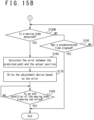
- the laser tracking device 1G tracks the moving body 3 through the procedure shown in FIGs. 15A and 15B .
- the laser tracking device 1G manually or automatically starts the procedure shown in FIGs. 15A and 15B .
- the processes of steps S100 to S130 are as described in relation to Embodiment 1, and accordingly no description thereof is given.
- the controller 152 determines whether the moving body 3 is detected. More specifically, the first light receiving device 140A measures a first photon count based on the first splitted light 23 that includes the reflected light 20 of the output light 10. Further, the second light receiving device 140B measures a second photon count based on the second splitted light 24 that includes reflected light of the sunlight and the like. The controller 152 determines, based on the measured first photon count and second photon count, whether at least one of the first splitted light 23 and the second splitted light 24 includes reflected light from the moving body 3. When determining that none of the first splitted light 23 and the second splitted light 24 includes reflected light from the moving body 3, the controller 152 performs the process of step S150. When determining that at least one of the first splitted light 23 and the second splitted light 24 includes reflected light from the moving body 3, the controller 152 performs the process of step S160.
- steps S150 to S180 are as described in relation to Embodiment 1, and accordingly no description thereof is given.
- the light receiving device 140 of the laser tracking device 1H may include a temperature measurement device 140C that measures the temperature of an object located in the axial direction of the telescope 130.
- the temperature measurement device 140C measures the temperature of the object located in the axial direction of the telescope 130 based on an infrared ray included in the second splitted light 24.
- the temperature measurement device 140C generates image data that represents the temperatures in various directions based on the second splitted light 24.
- the temperature measurement device 140C may be any temperature measurement device that measures the temperature of an object, not limited to the configuration that measures the temperature based on an infrared ray.
- the signal processor 151 detects the moving body 3 based on the photon count measured by the first light receiving device 140A and the image data generated by the temperature measurement device 140C. The signal processor 151 determines, based on the photon count measured by the first light receiving device 140A, whether the first splitted light 23 received by the first light receiving device 140A includes the reflected light 20 from the moving body 3. Further, the signal processor 151 determines, based on the image data generated by the temperature measurement device 140C, whether the moving body 3 exists within the range within which the temperature measurement device 140C performs the measurement. More specifically, the signal processor 151 determines whether the image data generated by the temperature measurement device 140C to represent the temperatures includes a region that represents the temperature of the moving body 3.
- the signal processor 151 When the first splitted light 23 received by the first light receiving device 140A includes the reflected light 20 or when the image data of the temperature measurement device 140C includes the region of the moving body 3, the signal processor 151 outputs to the controller 152 a detection signal that represents that the moving body 3 is detected.
- the signal processor 151 can detect the moving body 3 with high precision. Especially when the moving body 3 is a heat generating object, including a satellite with high power consumption such as a communication satellite and an optical satellite, the signal processor 151 can detect the moving body 3 with higher precision.
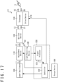
- the laser tracking device 1J may include a storage device 180 for setting the second angle ⁇ 2 shown in FIG. 7 .
- the second angle ⁇ 2 is the adjustment angle with which the adjustment device 110 adjusts the output direction of the output light 10 at the start of the tracking of the moving body 3.
- the storage device 180 stores parameters that influence the emission direction of the output light 10, such as the processing delay of the laser tracking device 1J, an error in the emission direction caused by a distortion of the telescope 130, errors caused by deterioration over time of various devices, and the like.
- the controller 152 retrieves the parameters from the storage device 180 to determine the second angle ⁇ 2 . This allows the laser tracking device 1J to correct an error related to the emission direction of the output light 10. It is noted that the storage device 180 may be incorporated in the controller 152.
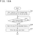
- the laser tracking device 1J tracks the moving body 3 through the procedure shown in FIGs. 18A and 18B .
- the laser tracking device 1J manually or automatically starts the procedure shown FIGs. 18A and 18B .
- the processes of steps S100 to S 110 are as described in relation to Embodiment 1, and accordingly no description thereof is given.
- the controller 152 drives the adjustment device 110 based on the parameters stored in the storage device 180 to adjust the emission direction of the output light 10. More specifically, the controller 152 retrieves the parameters stored in the storage device 180 and determines the second angle ⁇ 2 based on the retrieved parameters. The controller 152 drives the adjustment device 110 to set the adjustment angle of the output light 10 to the second angle ⁇ 2 thus determined.
- steps S130 to S180 are as described in relation to Embodiment 1, and accordingly no description thereof is given.
- the laser tracking device 1K may further includes an atmosphere measurement device 190.
- the atmosphere measurement device 190 measures the state of atmosphere along the light path of the output light 10, such as the temperature, the humidity, the atmospheric pressure, the refractive index of light caused by a turbulence, and the like, and outputs the measured state of atmosphere to the controller 152.
- the controller 152 determines the second angle ⁇ 2 shown in FIG. 7 based on the state of atmosphere. This allows the laser tracking device 1K to correct the error related to the emission direction of the output light 10.
- the atmosphere measurement device 190 may include, for example, a scintillometer that measures variations in the refractive index of light caused by a turbulence and a weather meter that measures the temperature, the humidity, the atmospheric pressure, and the like.
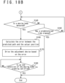
- the laser tracking device 1K performs a similar procedure to that performed in Embodiment 3 other than step S120B shown in FIG. 18B .
- the controller 152 retrieves the parameters from the storage device 180 and acquires the state of atmosphere from the atmosphere measurement device 190.
- the controller 152 calculates the second angle ⁇ 2 based on the parameters and the state of atmosphere. For example, the controller 152 calculates, based on the refractive index measured by the atmosphere measurement device 190, the second angle ⁇ 2 to emit the output light 10 onto the predicted path of the moving body 3.
- the controller 152 drives the adjustment device 110 to set the adjustment angle of the output light 10 to the second angle ⁇ 2 .
- the adjustment device 110 may be disposed at any position as long as the adjustment device 110 can adjust the output direction of the output light 10, not limited to these examples.
- the adjustment device 110 may be disposed in the telescope 130, for example, at the location of the third mirror 134 shown in FIG. 3 .
- the adjustment device 110 and the drive device 170 may rotate the output direction, for example, around an axis of the vertical direction, not limited to these examples.
- the configuration of the telescope 130 may be arbitrarily selected, not limited to the cylindrical shape, as long as the telescope 130 can output the output light 10 towards the moving body 3.
- the telescope 130 may be a frame formed by combining rod-shaped members that relatively fix the first mirror 132, the second mirror 133, the third mirror 134, and the fourth mirror 135.
- the adjustment device 110 sets the adjustment angle to the second angle ⁇ 2 from a time before the time ti when the tracking of the moving body 3 is started
- the adjustment angle may be set to any angle before the time ti when the tracking of the moving body 3 is started, as long as the adjustment angle is set to the second angle ⁇ 2 at the time ti.
- the adjustment angle may be set to a fourth angle ⁇ 4 between the second angle ⁇ 2 and the third angle ⁇ 3 before the time ti.
- the fourth angle ⁇ 4 may be, for example, the midpoint between the second angle ⁇ 2 and the third angle ⁇ 3 .
- the speed at which the emission direction of the output light 10 is modified by the optical element 111 of the adjustment device 110 is equal to the speed at which the emission direction of the output light 10 is modified by the rotation of the telescope 130 after the tracking start time ti until the detection time t 3 when the moving body 3 is detected
- the speed at which the emission direction of the output light 10 is modified by the optical element 111 is not limited to these examples.
- the speed at which the emission direction is modified by the optical element 111 may be arbitrarily selected as long as the speed at which the emission direction is modified by the optical element 111 is slower than or equal to the speed at which the emission direction of the output light 10 is modified by the rotation of the telescope 130.
- the modifying speed of the emission direction by the optical element 111 may be slower than the modifying speed of the emission direction by the rotation of the telescope 130.
- the emission direction of the output light 10 is modified along the predicted path of moving body 3 also after the tracking start time ti until the detection time t 3 . Since the emission direction of the output light 10 moves along the predicted path of the moving body 3, the laser tracking device 1 can detect the moving body 3 even when the velocity of the moving body 3 is high in comparison with emission intervals of the pulse laser for the output light 10.
- the light receiving device 140, the first light receiving device 140A, and the second light receiving device 140B measures a photon count based on light wave received by the telescope 130
- the light receiving device 140, the first light receiving device 140A, and the second light receiving device 140B are not limited to these examples. Any configuration may be selected for the light receiving device 140, the first light receiving device 140A, and the second light receiving device 140B as long as the light receiving device 140, the first light receiving device 140A, and the second light receiving device 140B can detect the reflected light 20 from the moving body 3.
- the light receiving device 140, the first light receiving device 140A, and the second light receiving device 140B may be an imaging device that receives light wave to generate image data, such as a camera.
- the signal processor 151 determines whether the moving body 3 is pictured in the image data generated by the light receiving device 140. When the moving body 3 is pictured in the image data, the signal processor 151 determines that the light wave received by the light receiving device 140 includes reflected light from the moving body 3. Also, one of the first light receiving device 140A and the second light receiving device 140B may be an imaging device.
- the laser tracking device may be configured by combining the configuration shown in FIG. 9 and the configuration shown in FIG. 14 .
- the light receiving device 140 includes the first light receiving device 140A and the second light receiving device 140B.
- the storage device 180 may be omitted with respect to the configuration shown in FIG. 19 .
- the controller 152 may determine the second angle ⁇ 2 based on the state of atmosphere informed from the atmosphere measurement device 190 without retrieving the parameters from the storage device 180.
- the laser oscillator 100 may be driven at any timing as long as the laser oscillator 100 generates the output when the tracking of the moving body 3 is started.
- the controller 152 may drive the laser oscillator 100 at step S110 in the procedure shown in FIG. 4A .
- the laser tracking devices described in the respective embodiments may be figured out, for example, as follows.
- a laser tracking device includes an adjustment device (110), a telescope (130), and a drive device (170).
- the adjustment device modifies an emission direction of first light wave (10).
- the drive device rotates the telescope based on a predicted path of a moving body (3).
- the adjustment device (110) modifies the emission direction to offset modification of the emission direction caused by the rotation of the telescope from a time when a tracking start condition is satisfied until the moving body is detected.
- the drive device rotates the telescope based on the predicted path of the moving body (3) and the adjustment device modifies the emission direction of the first light wave, it is possible to track the moving body without rapidly rotating the telescope. Further, since the adjustment device modifies the emission direction to offset the modification of the emission direction caused by the rotation of the telescope, it is possible to suppress the modification of the emission direction compared with the rotation of the telescope. This allows the laser tracking device to wait for the moving body reaching the emission direction of the output light of the laser tracking device.
- a laser tracking device which is configured as the laser tracking device according to the first aspect, is configured such that the speed at which the adjustment device modifies the emission direction is lower than or equal to the speed at which the emission direction is modified by the rotation of the telescope.
- a laser tracking device which is configured as the laser tracking device according to the first aspect, is configured such that the speed at which the adjustment device modifies the emission direction is equal to the speed at which the emission direction is modified by the rotation of the telescope.
- a laser tracking device which is configured as the laser tracking device according to the first aspect, includes a light receiving device (140) and a processing device (150).
- the processing device (150) is configured to determine that the moving body is detected when the light receiving device (140) receives second light wave (21, 21B, 22, 22B, 23) that includes reflected light (20) from the moving body (3).
- a laser tracking device which is configured as the laser tracking device according to the fourth aspect, includes a splitter device (120).
- the splitter device (120) is configured to guide the first light wave from the adjustment device to the telescope and guide the reflected light (20) from the telescope to the light receiving device.
- the splitter device allows the laser tracking device to achieve the emission of the output light and the reception of the reflected light with a single telescope.
- a laser tracking device which is configured as the laser tracking device according to the fourth aspect, includes a splitter device (120) that guides the first light wave (10) to the adjustment device.
- the adjustment device is configured to receive the reflected light (20) from the telescope and modify the travel direction of the received reflected light.
- the splitter device is configured to guide the reflected light from the adjustment device to the light receiving device.
- the travel direction of the reflected light is modified by the adjustment device, it is possible to use a light receiving device with a narrow field of view.
- the telescope (130) includes an emission telescope (130A) and a light receiving telescope (130B).
- the provision of the emission telescope that emits the first light wave (10) and the light receiving telescope that receives the reflected light (20) makes it possible to omit the splitter device (120).
- the adjustment device (110) is configured to incorporate an emission adjustment device (110A) and a light reception adjustment device (110B).
- the drive device (170) is configured to incorporate an emission drive device (170A) and a light reception drive device (170B).
- the light receiving device (140) includes a first light receiving device (140A) and a second light receiving device (140B).
- the second light wave (24) received by the second light receiving device does not include reflected light produced by the moving body reflecting the first light wave.
- the light receiving device (140) is configured to incorporate a first light receiving device (140A) and a temperature measurement device (140C).
- a laser tracking device which is configured as the laser tracking device according to the first aspect, is configured to incorporate a storage device (180) that stores a parameter that influences the emission direction.
- the laser tracking device can correct an error in relation to the emission direction of the first light wave.
- a laser tracking device which is configured as the laser tracking device according to the first aspect, is configured to incorporate an atmosphere measurement device (190).
- the laser tracking device can correct an error in relation to the emission direction of the first light wave.
Landscapes
- Physics & Mathematics (AREA)
- Engineering & Computer Science (AREA)
- General Physics & Mathematics (AREA)
- Computer Networks & Wireless Communication (AREA)
- Radar, Positioning & Navigation (AREA)
- Remote Sensing (AREA)
- Electromagnetism (AREA)
- Optics & Photonics (AREA)
- Optical Radar Systems And Details Thereof (AREA)
- Mechanical Light Control Or Optical Switches (AREA)
Abstract
Description
- The present invention relates to laser tracking devices.
- In recent years, researches have been made for laser tracking devices that use lasers to observe moving bodies that move in space, such as satellites, space debris, and the like. When tracking a moving body, a laser tracking device often waits for the moving body being detected in a state in which the optical axis of a telescope is directed to a given position on a predicted orbit of the moving body. After detecting the moving body, the laser tracking device moves the direction of the optical axis of the telescope in accordance with the moving velocity of the moving body.
- Here, large aperture telescopes are used to observe the positions of moving bodies with high precision. It is however difficult to quickly modify the optical axis direction of a large aperture telescope. Further, a laser tracking device requires controlling the optical axis direction of the telescope with high precision to observe the position of the moving body with improved precision. It is however difficult to control the optical axis direction of the telescope with high precision over a wide range. In view of this, the inventors have conceived of using a first optical system that modifies the optical axis direction with relatively low precision and a second optical system that modifies the optical axis direction with relatively high precision.
- Patent Literature 1 (
Japanese Patent Gazette No. 3382530 - [Patent Literature 1]
Japanese Patent Gazette No. 3382530 - In view of the above-described circumstances, one of objectives is to provide a laser tracking device that can track a moving body with high precision. Other objectives would be understood from the below-given recitation and the description of embodiments.
- A laser tracking device according to one embodiment for achieving the above-described objective includes an adjustment device, a telescope, and a drive device. The adjustment device modifies the emission direction of first light wave. The telescope emits the first light wave in the emission direction modified by the adjustment device. The drive device rotates the telescope based on a predicted path of the moving body. The adjustment device provides more precision in modifying the emission direction of the first light wave than in the drive device rotating the telescope. Further, the adjustment device modifies the emission direction to offset the modification of the emission direction caused by the rotation of the telescope from a time when a tracking start condition is satisfied until the moving body is detected.
- The above-described embodiment allows the laser tracking device to track the moving body with improved precision.
-
-
FIG. 1 is a schematic diagram of a laser tracking device, according to one embodiment. -
FIG. 2 is a configuration diagram of a laser tracking device, according to one embodiment. -
FIG. 3 is a configuration diagram of a telescope, according to one embodiment. -
FIG. 4A is a flowchart showing the operation of a laser tracking device, according to one embodiment. -
FIG. 4B is a flowchart showing the operation of a laser tracking device, according to one embodiment. -
FIG. 5 is a diagram for illustrating an operation in which a laser tracking device tracks a moving body, according to one embodiment. -
FIG. 6 is a diagram for illustrating the axial direction of a telescope rotated by a drive device, according to one embodiment. -
FIG. 7 is a diagram for illustrating the emission direction of output light adjusted by an adjustment device, according to one embodiment. -
FIG. 8 is a diagram for illustrating the emission direction of output light emitted by a laser tracking device, according to one embodiment. -
FIG. 9 is a configuration diagram of a laser tracking device, according to one embodiment. -
FIG. 10 is a configuration diagram of a laser tracking device, according to one embodiment. -
FIG. 11 is a configuration diagram of a laser tracking device, according to one embodiment. -
FIG. 12 is a configuration diagram of a laser tracking device, according to one embodiment. -
FIG. 13 is a configuration diagram of a laser tracking device, according to one embodiment. -
FIG. 14 is a configuration diagram of a laser tracking device, according to one embodiment. -
FIG. 15A is a flowchart showing the operation of a laser tracking device, according to one embodiment. -
FIG. 15B is a flowchart showing the operation of a laser tracking device, according to one embodiment. -
FIG. 16 is a configuration diagram of a laser tracking device, according to one embodiment. -
FIG. 17 is a configuration diagram of a laser tracking device, according to one embodiment. -
FIG. 18A is a flowchart showing the operation of a laser tracking device, according to one embodiment. -
FIG. 18B is a flowchart showing the operation of a laser tracking device, according to one embodiment. -
FIG. 19 is a configuration diagram of a laser tracking device, according to one embodiment. -
FIG. 20 is a diagram for illustrating the emission direction of output light adjusted by an adjustment device, according to one embodiment. -
FIG. 21 is a diagram for illustrating the emission direction of output light emitted by a laser tracking device, according to one embodiment. - As shown in
FIG. 1 , alaser tracking device 1 is installed, for example, on theground 2 and configured to detect the position of a movingbody 3. More specifically, thelaser tracking device 1 emits theoutput light 10 such as laser light to the movingbody 3 and detects the position of the movingbody 3 with high precision by receivingreflected light 20 from the movingbody 3. After detecting the position of the movingbody 3, thelaser tracking device 1 is configured to track the movingbody 3 by modifying the emission direction of theoutput light 10 to follow the movement of the movingbody 3. It is noted that themoving body 3 may include any moving object, for example, an object or flying body that circles around the earth, such as a satellite and a space debris. - As shown in
FIG. 2 , thelaser tracking device 1 includes alaser oscillator 100, anadjustment device 110, asplitter device 120, atelescope 130, alight receiving device 140, aprocessing device 150, and adrive device 170. Thedrive device 170 moves thetelescope 130 based on a predicted path of the movingbody 3. For example, thedrive device 170 rotates thetelescope 130 based on the predicted path of the movingbody 3. Theadjustment device 110 adjusts the emission direction of theoutput light 10 to detect the position of the movingbody 3. This allows thelaser tracking device 1 to, when detecting the movingbody 3, track the movingbody 3 without abruptly changing the speed at which thetelescope 130 is rotated. Further, thesplitter device 120 allows thelaser tracking device 1 to achieve both emission of theoutput light 10 and reception of the reflected light 20 by using thesingle telescope 130. It is noted that theadjustment device 110 provides more precision in controlling the emission direction of theoutput light 10 than in thedrive device 170 controlling the emission direction of theoutput light 10 by rotating thetelescope 130. - When the
laser tracking device 1 outputs theoutput light 10,initial light 11 emitted by thelaser oscillator 100 is outputted from thetelescope 130 via theadjustment device 110 and thesplitter device 120. - More specifically, as shown in
FIG. 3 , thelaser oscillator 100 outputs theinitial light 11, such as laser light, to theadjustment device 110. Thelaser oscillator 100 receives an emission signal generated by theprocessing device 150 and emits theinitial light 11. Theinitial light 11 may be pulse laser light, for example. - The
adjustment device 110 is configured to adjust the travel direction of theinitial light 11 and output the same as adjustedlight 12. By adjusting the travel direction of theinitial light 11 by theadjustment device 110, the emission direction of theoutput light 10 is modified around the axial direction of thetelescope 130. Theadjustment device 110 includes a rotatably-disposed optical element 111 such as a mirror, and anactuator 112 that rotates the optical element 111. The optical element 111 reflects theinitial light 11 to change the travel direction of theinitial light 11. Theactuator 112 is configured to rotate the optical element 111 with high resolution. For example, theactuator 112 is configured to adjust the rotation angle of the optical element 111, for example, in units of 10 microradians (µ rad). For example, theactuator 112 includes a piezo element and theadjustment device 110 includes a piezo mirror. The rotation axis of the optical element 111 may be arbitrarily selected. The optical element 111 may have one rotation axis or two rotation axes. It is noted that theactuator 112 is driven based on a control signal generated by theprocessing device 150. - The
splitter device 120 is configured to guide light wave from thelaser oscillator 100, such as the adjustedlight 12, into thetelescope 130. Thesplitter device 120 is also configured to guide acquired light 21 received from thetelescope 130 to thelight receiving device 140. For example, thesplitter device 120 includes a half mirror and directly guides the adjusted light 12 into thetelescope 130 by letting the adjusted light 12 pass therethrough while reflecting the acquired light 21 as splitted light 22 to directly guide thesplitted light 22 into thelight receiving device 140. - The
telescope 130 may be configured, for example, as a Coude reflecting telescope. Thetelescope 130 includes atube 131 and a plurality of mirrors, for example, afirst mirror 132, asecond mirror 133, athird mirror 134, and afourth mirror 135. The adjustedlight 12 is reflected in turn by thefourth mirror 135, thethird mirror 134, thesecond mirror 133, and thefirst mirror 132 and outputted as theoutput light 10 from an aperture disposed at one end of thetube 131. - The
tube 131 is cylindrically shaped and configured to output theoutput light 10 from the one end thereof. Thetube 131 also includes anaperture 139 at the side face thereof through which the adjustedlight 12 is introduced. - The
fourth mirror 135 is configured to guide the adjusted light 12 outputted from thesplitter device 120 into thetube 131 through theaperture 139 of thetube 131. Thefourth mirror 135 includes a plurality of mirrors and is configured to guide the adjusted light 12 outputted from thesplitter device 120 into thetube 131 regardless of the axial direction of thetube 131. - The
third mirror 134, thesecond mirror 133, and thefirst mirror 132 are arranged to output theoutput light 10 from an end of thetube 131. More specifically, thefirst mirror 132 is disposed at the end of thetube 131 in the opposite direction of the direction in which theoutput light 10 is outputted. Thefirst mirror 132 has a concave reflecting surface. Thesecond mirror 133 is disposed at the focal position of thefirst mirror 132. Thesecond mirror 133 has a convex reflecting surface. Thethird mirror 134 is arranged to reflect the adjusted light 12 reflected by thefourth mirror 135 towards thesecond mirror 133. The adjustedlight 12 is reflected in thetube 131 by thethird mirror 134, thesecond mirror 133, and thefirst mirror 132 and outputted as theoutput light 10 from one end of thetube 131. - It is noted that any telescope structures may be selected for the
telescope 130, not limited to the Coude reflecting telescope structure. For example, a Nasmyth reflecting telescope structure may be selected for thetelescope 130. In this case, thedrive device 170 may rotate thelaser oscillator 100, theadjustment device 110, thesplitter device 120, and thelight receiving device 140 in accordance with the rotation of thetelescope 130 when the emission direction of theoutput light 10 is rotated to a direction in the horizontal plane. - A Galilean telescope structure may be selected for the
telescope 130. In this case, thedrive device 170 may rotate thelaser oscillator 100, theadjustment device 110, thesplitter device 120, and thelight receiving device 140 in accordance with the rotation of thetelescope 130. - As described above, the light wave outputted by the
laser oscillator 100 is outputted from one end of thetelescope 130. - As shown in
FIG. 2 , the reflected light 20 from the movingbody 3 is received by thelight receiving device 140 via thetelescope 130 and thesplitter device 120. - As shown in
FIG. 3 , thetelescope 130 outputs to thesplitter device 120 the reflected light 20 that reaches the end of thetelescope 130 as acquiredlight 21. More specifically, the reflectedlight 20 is reflected by thefirst mirror 132, thesecond mirror 133, and thethird mirror 134 and outputted from theaperture 139 of thetube 131. The reflected light 20 outputted from thetube 131 is reflected by thefourth mirror 135 and guided to thesplitter device 120. The fourth mirror includes a plurality of mirrors and is configured to guide the reflected light 20 outputted from theaperture 139 of thetube 131 to thesplitter device 120, regardless of the direction in which the axial direction of thetube 131 is directed. - The
splitter device 120 is configured to guide the acquired light 21 to thelight receiving device 140 as splittedlight 22. For example, thesplitter device 120 includes a half mirror and reflects the acquired light 21 as thesplitted light 22 to a direction different from the light axis direction of the adjustedlight 12. As such, thesplitter device 120 is configured to guide the adjusted light 12 from thelaser oscillator 100 to thetelescope 130 and also guide the acquired light 21 from thetelescope 130 to thelight receiving device 140. - As described above, the light wave received by the
telescope 130 is guided to thelight receiving device 140. - The
light receiving device 140 measures, based on thesplitted light 22 received from thesplitter device 120, a photon count of thesplitted light 22, for example, the number of photons included in thesplitted light 22. When the movingbody 3 exists within the emission range of theoutput light 10, the measured photon count includes the number of photons corresponding to the reflected light 20 from the movingbody 3. As shown inFIG. 2 , thelight receiving device 140 transmits the measured photon count to thesignal processor 151 of theprocessing device 150. The photon count may include the time of the light reception. Thelight receiving device 140 may be a photometer, for example. - The
processing device 150 includes asignal processor 151 and acontroller 152. Theprocessing device 150 performs various processes to control thelaser tracking device 1. For example, theprocessing device 150 is a computer that includes a central processor unit (CPU), a storage device, and other devices, for example. Theprocessing device 150 may include one or more computers. - The
signal processor 151 detects a movingbody 3 based on the photon count from thelight receiving device 140. Thesignal processor 151 determines whether thesplitted light 22 incudes the reflected light 20 from the movingbody 3 based on changes in the photon count. When thesplitted light 22 incudes the reflected light 20 from the movingbody 3, thesignal processor 151 outputs to the controller 152 a detection signal that indicates that the movingbody 3 is detected. - The
controller 152 controls thelaser oscillator 100, theadjustment device 110, and thedrive device 170. Thecontroller 152 controls thedrive device 170 based on the predicted path of the movingbody 3 to rotate thetelescope 130. Thecontroller 152 further specifies the timing at which thelaser oscillator 100 is to emit theinitial light 11. Thecontroller 152 further controls theadjustment device 110 based on the detection signal from thesignal processor 151 such that theoutput light 10 is emitted to the movingbody 3. - The
laser tracking device 1 tracks the movingbody 3 through the procedure shown inFIGs. 4A and4B . When tracking the movingbody 3, thelaser tracking device 1 manually or automatically starts the procedure shown inFIGs. 4A and4B . At step S100, thecontroller 152 controls thedrive device 170 based on a predicted path of the movingbody 3 to move thetelescope 130. More specifically, thecontroller 152 acquires the predicted path of the movingbody 3 from an external entity. The predicted path represents the path along which the movingbody 3 will move and the positions of the movingbody 3 at predetermined instances of time. Thecontroller 152 generates, based on the predicted path, a signal that controls thedrive device 170 such that the axis of thetelescope 130 is directed towards a predicted position of the movingbody 3. Thedrive device 170 rotates thetelescope 130 such that the axis of thetelescope 130 is directed towards the predicted position of the movingbody 3. - For example, as shown in
FIG. 5 , an assumption is made that the movingbody 3 passes right overhead of thelaser tracking device 1. In this case, thecontroller 152 rotates thetelescope 130 such that the angle θ between thehorizontal plane 5 and theaxis direction 6 of thetelescope 130 is equal to the angle between thehorizontal plane 5 and the predicted direction from thelaser tracking device 1 to the movingbody 3. More specifically, as shown inFIG. 6 , thecontroller 152 accelerates the rotation speed of thetelescope 130 to the speed corresponding to the travel speed of the movingbody 3 and rotates thetelescope 130 to move theaxis direction 6 of thetelescope 130 along the predicted path of the movingbody 3 at step S100. - At step S110 shown in
FIG. 4A , thecontroller 152 determines whether a tracking start condition is satisfied. The tracking start condition may include any conditions, such as the instance of time, the position of the movingbody 3, the error between the rotation speed of thetelescope 130 and the predicted path of the movingbody 3, and the like. For example, thecontroller 152 determines that the tracking start condition is satisfied when the tracking start time has been reached. When determining that the tracking start condition is satisfied, thecontroller 152 performs the process of step S120. When determining that the tracking start condition is not satisfied, thecontroller 152 repeats stepS 110 until the tracking start condition is satisfied. For example, an assumption is made that thecontroller 152 starts the tracking at a tracking start time ti. In this case, as shown inFIG. 6 , thecontroller 152 rotates thetelescope 130 at the tracking start time ti such that the axis direction of thetelescope 130 is at a first angle θ1 which is the same as the direction of the movingbody 3. Further, thecontroller 152 rotates thetelescope 130 such that the rotation speed of thetelescope 130 reaches the speed corresponding to a predicted speed of the movingbody 3 at the tracking start time ti. - When the tracking start condition is satisfied, at step S120 shown in
FIG. 4A , thecontroller 152 drives theadjustment device 110 to adjust the emission direction of theoutput light 10. For example, when the tracking start condition is satisfied, thecontroller 152 drives theadjustment device 110 such that the emission direction of theoutput light 10 is kept at a predetermined angle θ. More specifically, as shown inFIG. 7 , thecontroller 152 controls, before the tracking start time ti at which the tracking start condition is satisfied, theadjustment device 110 such that the adjustment angle with which theadjustment device 110 adjusts the emission direction of theoutput light 10 is a second angle θ2. The second angle θ2 is the maximum value of the adjustment angle adjustable by theadjustment device 110. When the tracking start time ti has been reached, thecontroller 152 rotates theadjustment device 110 to a direction to reduce the angle θ. Theactuator 112 of theadjustment device 110 rotates the optical element 111 based on the control signal from thecontroller 152 to offset the modification in the emission direction of theoutput light 10 caused by the rotation of thetelescope 130. Accordingly, as shown inFIG. 8 , the emission direction of theoutput light 10 is kept unchanged for a predetermined time duration after the tracking start time ti. - At step S130 shown in
FIG. 4A , thecontroller 152 starts emission of theinitial light 11 by driving thelaser oscillator 100. Theinitial light 11 is for example, pulse laser light with a specified wavelength. As a result, theoutput light 10 is emitted in a specified direction, more specifically, to the angle of the sum of θ1 and θ2 for the predetermined time after the tracking start time ti. - At step S140 shown in
FIG. 4B , thecontroller 152 determines whether the movingbody 3 is detected. More specifically, thelight receiving device 140 measures a photon count based on the light wave received by thetelescope 130. Thecontroller 152 determines, based on the measured photon count, whether the light wave received by thetelescope 130 includes the reflected light 20 from the movingbody 3. Thecontroller 152 performs the process of step S150 when determining that the light wave received by thetelescope 130 does not include the reflectedlight 20. Thecontroller 152 performs the process of step S160 when determining that the light wave received by thetelescope 130 includes the reflectedlight 20. - At step S150, the
controller 152 determines whether a predetermined time has elapsed after the tracking start condition is satisfied. When the predetermined time has not elapsed after the tracking start time ti, thecontroller 152 returns to the process of step S140 to continue the detection of the movingbody 3. When the predetermined time has elapsed after the tracking start time ti, thecontroller 152 determines that it is impossible to detect the movingbody 3 and terminates the tracking process, stopping thelaser oscillator 100, thedrive device 170, and the like. For example, as shown inFIG. 7 , the predetermined time is the time until the adjustment angle by theadjustment device 110 reaches a third angle θ3, that is, the time between the tracking start time ti and a tracking limit time t2. The third angle θ3 is, for example, the minimum value of the adjustment angle adjustable by theadjustment device 110. - When detecting the moving
body 3, at step S160 shown inFIG. 4B , thecontroller 152 calculates the error between the position of the movingbody 3 and the predicted path of the movingbody 3 based on the time when the movingbody 3 is detected. For example, thecontroller 152 calculates the direction of the movingbody 3 with respect to thelaser tracking device 1 based on the emission direction of theoutput light 10 at the time when the movingbody 3 is detected. Further, thecontroller 152 calculates the distance from thelaser tracking device 1 to the movingbody 3 based on the time when the movingbody 3 is detected (for example, the time when the reflectedlight 20 is received) and the time when theoutput light 10 is emitted. This allows thecontroller 152 to calculate the precise position of the movingbody 3. Further, thecontroller 152 calculates the error between the predicted path of the movingbody 3 and the current position of the movingbody 3 based on the time when the reflectedlight 20 is received or the time when theoutput light 10 is emitted. - At step S170, the
controller 152 drives theadjustment device 110 based on the calculated error. More specifically, thecontroller 152 calculates an adjustment angle of theadjustment device 110 based on the calculated error such that the emission direction of theoutput light 10 is directed towards the movingbody 3 and sets theadjustment device 110 to the calculated adjustment angle. As shown inFIG. 7 , after the detection time t3 when the movingbody 3 is detected, thecontroller 152 maintains the adjustment error of theadjustment device 110 in accordance with the calculated adjustment error. Thedrive device 170 rotates thetelescope 130 along the predicted path of the movingbody 3, and theadjustment device 110 is set to the adjustment angle in accordance with the error. As such, as shown inFIG. 8 , thecontroller 152 drives thetelescope 130 along the predicted path of the movingbody 3 to track the movingbody 3. - At step S180 shown in
FIG 4B , thecontroller 152 determines whether an end condition to terminate the tracking of the movingbody 3 is satisfied. When determining the end condition is not satisfied, thecontroller 152 repeats the process of step S180 until the end condition is satisfied. When determining that the end condition is satisfied, thecontroller 152 stops the tracking of the movingbody 3, stopping respective devices of thelaser tracking device 1, including thelaser oscillator 100, theadjustment device 110, thedrive device 170, and the like. For example, the end condition may be that a predetermined time has elapsed after the start of the tracking. When the predetermined time has elapsed after the start of the tracking, for example, when the predetermined time has elapsed from the detection time t3, thecontroller 152 determines that the end condition is satisfied and stops the respective devices of thelaser tracking device 1. - It is noted that, at step S180, the
controller 152 measures the distance from thelaser tracking device 1 to the movingbody 3 based on the time duration from the emission of theinitial light 11 by thelaser oscillator 100 to the reception of thesplitted light 22 by thelight receiving device 140. Further, thecontroller 152 calculates the direction of the movingbody 3 with respect to thelaser tracking device 1 based on the axial direction of thetelescope 130 controlled by thedrive device 170 and the adjustment angle of the emission direction of theoutput light 10 controlled by theadjustment device 110. Thecontroller 152 determines the position of the movingbody 3 based on the measured distance to the movingbody 3 and the direction of the movingbody 3. In this way, thelaser tracking device 1 tracks the movingbody 3. - As shown in
FIG. 9 , theadjustment device 110 of thelaser tracking device 1B may adjust the travel direction of the reflectedlight 20 and emit to thelight receiving device 140 the reflected light 20 with the travel direction thereof adjusted. Thelaser tracking device 1B is allowed to use alight receiving device 140 with a narrow field of view since the travel direction of the light wave received by thelight receiving device 140 is adjusted by theadjustment device 110. In this case, theadjustment device 110 is disposed between thetelescope 130 and thesplitter device 120 in terms of the optical path. - When the
output light 10 is to be emitted, thelaser oscillator 100 emits theinitial light 11 to thesplitter device 120. Thesplitter device 120 emits theinitial light 11 to guide theinitial light 11 to theadjustment device 110. Theadjustment device 110 adjusts the travel direction of theinitial light 11 emitted from thesplitter device 120 and guides theinitial light 11 to thetelescope 130 as the adjustedlight 12. Thetelescope 130 emits the adjusted light 12 as theoutput light 10 in the axial direction of thetelescope 130. Detailed configurations of the respective devices are as described in relation toEmbodiment 1, and accordingly no description thereof is given. - When receiving the reflected
light 20, thetelescope 130 outputs, as the acquired light 21, the reflected light 20 that reaches one end thereof to theadjustment device 110. Theadjustment device 110 adjusts the travel direction of the acquiredlight 21. The acquired light 21B with the travel direction thereof adjusted is emitted to thesplitter device 120. Thesplitter device 120 outputs the acquired light 21B such that the acquired light 21B is guided to thelight receiving device 140 as splitted light 22B. Thelight receiving device 140 measures a photon count based on the splitted light 22B received from thesplitter device 120. Detailed configurations of the respective devices are as described inEmbodiment 1, and accordingly no description thereof is given. - The operation of the
laser tracking device 1B is also as described in relation toEmbodiment 1, and accordingly no description thereof is given. - As shown in
FIG. 10 , thetelescope 130 of the laser tracking device 1C may include anemission telescope 130A and alight receiving telescope 130B. The emission telescope 130Ais configured to emit theoutput light 10 and thelight receiving telescope 130B is configured to receive the reflectedlight 20. Thelight receiving telescope 130B is relatively fixed to theemission telescope 130A and thedrive device 170 rotates theemission telescope 130A and thelight receiving telescope 130B. Since the reflectedlight 20 is separated from the light axis of theoutput light 10 in the laser tracking device 1C, thesplitter device 120 is omitted. - When the
output light 10 is to be emitted, thelaser oscillator 100 emits theinitial light 11 to theadjustment device 110. Theadjustment device 110 adjusts the travel direction of theinitial light 11 emitted from thelaser oscillator 100 and guides theinitial light 11 to theemission telescope 130A as the adjustedlight 12. Theemission telescope 130A emits the adjusted light 12 as theoutput light 10 in the axial direction of theemission telescope 130A. The detailed configuration of theemission telescope 130A is similar to thetelescope 130 ofEmbodiment 1 and detailed configurations of other respective devices are also as described in relation toEmbodiment 1. Accordingly, no descriptions thereof are given. - When receiving the reflected
light 20, thelight receiving telescope 130B outputs, as the acquired light 21, the reflected light 20 that reaches one end thereof to thelight receiving device 140. Thelight receiving device 140 measures a photon count based on the acquired light 21 received from thelight receiving telescope 130B. The detailed configuration of thelight receiving telescope 130B is similar to thetelescope 130 ofEmbodiment 1 and detailed configurations of other respective devices are also as described in relation toEmbodiment 1. Accordingly, no descriptions thereof are given. - The operation of the laser tracking device 1C is also as described in relation to
Embodiment 1, and accordingly no description thereof is given. - As shown in
FIG. 11 , thetelescope 130 of thelaser tracking device 1D may include anemission telescope 130A and alight receiving telescope 130B while theadjustment device 110 may include anemission adjustment device 110A and a lightreception adjustment device 110B. Theemission adjustment device 110A adjusts the output direction of theoutput light 10 similarly to theadjustment device 110 ofEmbodiment 1. The lightreception adjustment device 110B adjusts the travel direction of the reflectedlight 20 and emits the reflected light 20 with the travel direction thereof adjusted to thelight receiving device 140. Thelaser tracking device 1D is allowed to use alight receiving device 140 with a narrow field of view since the travel direction of light wave received by thelight receiving device 140 is adjusted by theadjustment device 110. Further, since the reflectedlight 20 is separated from the light axis of theoutput light 10 in thelaser tracking device 1D, thesplitter device 120 is omitted. - When the
output light 10 is to be emitted, thelaser oscillator 100 emits theinitial light 11 to theemission adjustment device 110A. Theadjustment device 110 adjusts the travel direction of theinitial light 11 emitted from thelaser oscillator 100 and guides theinitial light 11 to theemission telescope 130A as the adjustedlight 12. Theemission telescope 130A emits the adjusted light 12 as theoutput light 10 in the axial direction of theemission telescope 130A. The detailed configuration of theemission adjustment device 110A is similar to theadjustment device 110 ofEmbodiment 2 and detailed configurations of other respective devices are as described in relation to Variation Example 2. Accordingly, no descriptions thereof are given. - When receiving the reflected
light 20, thelight receiving telescope 130B outputs, as the acquired light 21, the reflected light 20 that reaches one end thereof to the lightreception adjustment device 110B. The lightreception adjustment device 110B adjusts the travel direction of the acquired light 21 and outputs the acquired light 21 to thelight receiving device 140 as the acquired light 21B. Thelight receiving device 140 measures a photon count based on the acquired light 21B received from the lightreception adjustment device 110B. The detailed configuration of the lightreception adjustment device 110B is similar to theadjustment device 110 ofEmbodiment 2 and detailed configurations of other respective devices are as described in relation to Variation Example 2. Accordingly, no descriptions thereof are given. - The operation of the
laser tracking device 1D is also as described in relation toEmbodiment 1, and accordingly no description thereof is given. - As shown in
FIG. 12 , thetelescope 130 of thelaser tracking device 1E may include anemission telescope 130A and alight receiving telescope 130B while thedrive device 170 may include anemission drive device 170A and a lightreception drive device 170B. Theemission telescope 130A is configured to emit theoutput light 10 and thelight receiving telescope 130B is configured to receive the reflectedlight 20. Theemission drive device 170A is configured to rotate theemission telescope 130A to direct the axial direction of theemission telescope 130A towards the movingbody 3 while the lightreception drive device 170B is configured to rotate thelight receiving telescope 130B to direct the axial direction of thelight receiving telescope 130B towards the movingbody 3. - The
emission telescope 130A is configured to rotate independently of thelight receiving telescope 130B, which allows theemission telescope 130A to be disposed apart from thelight receiving telescope 130B. Further, since the reflectedlight 20 is separated from the light axis of theoutput light 10 in thelaser tracking device 1E, thesplitter device 120 is omitted. - When the
output light 10 is to be emitted, thelaser oscillator 100 emits theinitial light 11 to theadjustment device 110. Theadjustment device 110 adjusts the travel direction of theinitial light 11 emitted from thelaser oscillator 100 and guides theinitial light 11 to theemission telescope 130A as the adjustedlight 12. Theemission telescope 130A emits the adjusted light 12 as theoutput light 10 in the axial direction of theemission telescope 130A. Detailed configurations of respective devices are as described in relation to Variation Example 2, and accordingly no description thereof is given. - When receiving the reflected
light 20, thelight receiving telescope 130B outputs, as the acquired light 21, the reflected light 20 that reaches one end thereof to thelight receiving device 140. Thelight receiving device 140 measures a photon count based on the acquired light 21 received from thelight receiving telescope 130B. Detailed configurations of respective devices are as described in relation to Variation Example 2, and accordingly no description thereof is given. - The operation of the
laser tracking device 1E is as described in relation toEmbodiment 1, and accordingly no description thereof is given. - As shown in
FIG. 13 , thetelescope 130 of thelaser tracking device 1F may include anemission telescope 130A and alight receiving telescope 130B while thedrive device 170 may include anemission drive device 170A and a lightreception drive device 170B. Further, theadjustment device 110 may include anemission adjustment device 110A and a lightreception adjustment device 110B. Theemission adjustment device 110A adjusts the output direction of theoutput light 10 similarly to theemission adjustment device 110A of Variation Example 3. The lightreception adjustment device 110B adjusts the travel direction of the reflectedlight 20 and emits the reflected light 20 with the travel direction thereof adjusted to thelight receiving device 140, similarly to the lightreception adjustment device 110B of Variation Example 3. The detailed configurations of thetelescope 130 and thedrive device 170 are as described in relation to Variation Example 4, and accordingly no descriptions thereof are given. - The
laser tracking device 1F is allowed to use alight receiving device 140 with a narrow field of view since the travel direction of light wave received by thelight receiving device 140 is adjusted by theadjustment device 110. Theemission telescope 130A is configured to rotate independently of thelight receiving telescope 130B, which allows theemission telescope 130A to be disposed apart from thelight receiving telescope 130B. Further, since the reflectedlight 20 is separated from the light axis of theoutput light 10 in thelaser tracking device 1F, thesplitter device 120 is omitted. - When the
output light 10 is to be emitted, thelaser oscillator 100 emits theinitial light 11 to theemission adjustment device 110A. Theemission adjustment device 110A adjusts the travel direction of theinitial light 11 emitted from thelaser oscillator 100 and guides theinitial light 11 to theemission telescope 130A as the adjustedlight 12. Theemission telescope 130A emits the adjusted light 12 as theoutput light 10 in the axial direction of theemission telescope 130A. Theemission adjustment device 110A is as described in relation to Variation Example 3 and detailed configurations of other respective devices are as described in relation to Variation Example 4. Accordingly, no descriptions thereof are given. - When receiving the reflected
light 20, thelight receiving telescope 130B outputs, as the acquired light 21, the reflected light 20 that reaches one end thereof to the lightreception adjustment device 110B. The lightreception adjustment device 110B adjusts the travel direction of the acquired light 21 and outputs the acquired light 21 to thelight receiving device 140 as acquired light 21B. Thelight receiving device 140 measures a photon count based on the acquired light 21B received from the lightreception adjustment device 110B. The detailed configuration of the lightreception adjustment device 110B is as described in relation to Variation Example 3 and detailed configurations of other respective devices are as described in relation to Variation Example 4. Accordingly, no descriptions thereof are given. - The operation of the
laser tracking device 1F is as described in relation toEmbodiment 1, and accordingly no description thereof is given. - As shown in
FIG. 14 , thelight receiving device 140 of the laser tracking device 1G may include a firstlight receiving device 140A and a secondlight receiving device 140B. In this case, thesplitter device 120 splits the acquired light 21 received from thetelescope 130 into first splittedlight 23 to be guided to the firstlight receiving device 140A and secondsplitted light 24 to be guided to the secondlight receiving device 140B. Thesplitter device 120 includes, for example, a beam splitter that splits the acquired light 21 into the first splittedlight 23 and the secondsplitted light 24. - The first
light receiving device 140A receives the reflectedlight 20, which is produced by theoutput light 10 outputted from thetelescope 130 being reflected by the movingbody 3. Meanwhile, the secondlight receiving device 140B receives light wave emitted from the movingbody 3, for example, reflected light of the sunlight. - To receive the reflected
light 20 of theoutput light 10, the firstlight receiving device 140A may include an optical filter, such as a band filter, that allows passage of light in a band that includes the wavelength band of theoutput light 10. The firstlight receiving device 140A measures a photon count based on the reflectedlight 20 of theoutput light 10. - To receive light wave other than the reflected
light 20 of theoutput light 10, the secondlight receiving device 140B may include an optical filter, such as a long pass filter, a short pass filter or the like, that cuts off light of the wavelength band of theoutput light 10. The secondlight receiving device 140B measures a photon count based on light wave emitted from the movingbody 3, such as reflected light of the sunlight. - The
signal processor 151 detects the movingbody 3 based on the photon count measured by the firstlight receiving device 140A and the photon count measured by the secondlight receiving device 140B. Thesignal processor 151 determines whether any of the light wave received by the firstlight receiving device 140A and the light wave received by the secondlight receiving device 140B includes reflected light from the movingbody 3. When the received light wave includes the reflected light, thesignal processor 151 outputs to the controller 152 a detection signal that represents that the movingbody 3 is detected. - By the
light receiving device 140 receiving light wave emitted from the movingbody 3 in addition to the reflectedlight 20 of theoutput light 10, thesignal processor 151 can detect the movingbody 3 with high probability. For example, let pulse laser light be emitted as theoutput light 10. Even in the case when the movingbody 3 crosses the emitting line of theoutput light 10 while emission of theoutput light 10 is halted, thesignal processor 151 can detect the movingbody 3 by receiving the reflected light of the sunlight. Further, even in the case when the emission direction of theoutput light 10 is misaligned from the actual position of the movingbody 3 due to an error in the predicted path of the movingbody 3 and/or an error in the emission direction, thesignal processor 151 can detect the movingbody 3 by receiving the reflected light of the sunlight. - The configuration of the rest is as described in relation to
Embodiment 1, and accordingly no description thereof is given. - The laser tracking device 1G tracks the moving
body 3 through the procedure shown inFIGs. 15A and15B . When tracking the movingbody 3, the laser tracking device 1G manually or automatically starts the procedure shown inFIGs. 15A and15B . The processes of steps S100 to S130 are as described in relation toEmbodiment 1, and accordingly no description thereof is given. - At step S140B of
FIG. 15B , thecontroller 152 determines whether the movingbody 3 is detected. More specifically, the firstlight receiving device 140A measures a first photon count based on the first splittedlight 23 that includes the reflectedlight 20 of theoutput light 10. Further, the secondlight receiving device 140B measures a second photon count based on the secondsplitted light 24 that includes reflected light of the sunlight and the like. Thecontroller 152 determines, based on the measured first photon count and second photon count, whether at least one of the first splittedlight 23 and the secondsplitted light 24 includes reflected light from the movingbody 3. When determining that none of the first splittedlight 23 and the secondsplitted light 24 includes reflected light from the movingbody 3, thecontroller 152 performs the process of step S150. When determining that at least one of the first splittedlight 23 and the secondsplitted light 24 includes reflected light from the movingbody 3, thecontroller 152 performs the process of step S160. - The processes of steps S150 to S180 are as described in relation to
Embodiment 1, and accordingly no description thereof is given. - As shown in
FIG. 16 , thelight receiving device 140 of thelaser tracking device 1H may include atemperature measurement device 140C that measures the temperature of an object located in the axial direction of thetelescope 130. For example, thetemperature measurement device 140C measures the temperature of the object located in the axial direction of thetelescope 130 based on an infrared ray included in the secondsplitted light 24. In this case, thetemperature measurement device 140C generates image data that represents the temperatures in various directions based on the secondsplitted light 24. It is noted that thetemperature measurement device 140C may be any temperature measurement device that measures the temperature of an object, not limited to the configuration that measures the temperature based on an infrared ray. - The
signal processor 151 detects the movingbody 3 based on the photon count measured by the firstlight receiving device 140A and the image data generated by thetemperature measurement device 140C. Thesignal processor 151 determines, based on the photon count measured by the firstlight receiving device 140A, whether the first splittedlight 23 received by the firstlight receiving device 140A includes the reflected light 20 from the movingbody 3. Further, thesignal processor 151 determines, based on the image data generated by thetemperature measurement device 140C, whether the movingbody 3 exists within the range within which thetemperature measurement device 140C performs the measurement. More specifically, thesignal processor 151 determines whether the image data generated by thetemperature measurement device 140C to represent the temperatures includes a region that represents the temperature of the movingbody 3. When the first splittedlight 23 received by the firstlight receiving device 140A includes the reflected light 20 or when the image data of thetemperature measurement device 140C includes the region of the movingbody 3, thesignal processor 151 outputs to the controller 152 a detection signal that represents that the movingbody 3 is detected. - Since the
light receiving device 140 detects the temperature of the movingbody 3, thesignal processor 151 can detect the movingbody 3 with high precision. Especially when the movingbody 3 is a heat generating object, including a satellite with high power consumption such as a communication satellite and an optical satellite, thesignal processor 151 can detect the movingbody 3 with higher precision. - The configuration and operation of the rest are as described in relation to
Embodiment 2, and accordingly no description thereof is given. - As shown in
FIG. 17 , the laser tracking device 1J may include astorage device 180 for setting the second angle θ2 shown inFIG. 7 . The second angle θ2 is the adjustment angle with which theadjustment device 110 adjusts the output direction of theoutput light 10 at the start of the tracking of the movingbody 3. Thestorage device 180 stores parameters that influence the emission direction of theoutput light 10, such as the processing delay of the laser tracking device 1J, an error in the emission direction caused by a distortion of thetelescope 130, errors caused by deterioration over time of various devices, and the like. Thecontroller 152 retrieves the parameters from thestorage device 180 to determine the second angle θ2. This allows the laser tracking device 1J to correct an error related to the emission direction of theoutput light 10. It is noted that thestorage device 180 may be incorporated in thecontroller 152. - The laser tracking device 1J tracks the moving
body 3 through the procedure shown inFIGs. 18A and18B . When tracking the movingbody 3, the laser tracking device 1J manually or automatically starts the procedure shownFIGs. 18A and18B . The processes of steps S100 toS 110 are as described in relation toEmbodiment 1, and accordingly no description thereof is given. - At step S120B, the
controller 152 drives theadjustment device 110 based on the parameters stored in thestorage device 180 to adjust the emission direction of theoutput light 10. More specifically, thecontroller 152 retrieves the parameters stored in thestorage device 180 and determines the second angle θ2 based on the retrieved parameters. Thecontroller 152 drives theadjustment device 110 to set the adjustment angle of theoutput light 10 to the second angle θ2 thus determined. - The processes of steps S130 to S180 are as described in relation to
Embodiment 1, and accordingly no description thereof is given. - As shown in
FIG. 19 , thelaser tracking device 1K may further includes anatmosphere measurement device 190. Theatmosphere measurement device 190 measures the state of atmosphere along the light path of theoutput light 10, such as the temperature, the humidity, the atmospheric pressure, the refractive index of light caused by a turbulence, and the like, and outputs the measured state of atmosphere to thecontroller 152. Thecontroller 152 determines the second angle θ2 shown inFIG. 7 based on the state of atmosphere. This allows thelaser tracking device 1K to correct the error related to the emission direction of theoutput light 10. It is noted that theatmosphere measurement device 190 may include, for example, a scintillometer that measures variations in the refractive index of light caused by a turbulence and a weather meter that measures the temperature, the humidity, the atmospheric pressure, and the like. - The
laser tracking device 1K performs a similar procedure to that performed inEmbodiment 3 other than step S120B shown inFIG. 18B . At step S120B, thecontroller 152 retrieves the parameters from thestorage device 180 and acquires the state of atmosphere from theatmosphere measurement device 190. Thecontroller 152 calculates the second angle θ2 based on the parameters and the state of atmosphere. For example, thecontroller 152 calculates, based on the refractive index measured by theatmosphere measurement device 190, the second angle θ2 to emit theoutput light 10 onto the predicted path of the movingbody 3. Thecontroller 152 drives theadjustment device 110 to set the adjustment angle of theoutput light 10 to the second angle θ2. - Although examples have been presented in which the
adjustment device 110 is disposed out of thetelescope 130 in the respective embodiments, theadjustment device 110 may be disposed at any position as long as theadjustment device 110 can adjust the output direction of theoutput light 10, not limited to these examples. For example, theadjustment device 110 may be disposed in thetelescope 130, for example, at the location of thethird mirror 134 shown inFIG. 3 . - Although examples have been presented in which the
adjustment device 110 and thedrive device 170 modify the angle between thehorizontal plane 5 and the output direction of theoutput light 10 in the respective embodiments, theadjustment device 110 and thedrive device 170 may rotate the output direction, for example, around an axis of the vertical direction, not limited to these examples. - The configuration of the
telescope 130 may be arbitrarily selected, not limited to the cylindrical shape, as long as thetelescope 130 can output theoutput light 10 towards the movingbody 3. For example, thetelescope 130 may be a frame formed by combining rod-shaped members that relatively fix thefirst mirror 132, thesecond mirror 133, thethird mirror 134, and thefourth mirror 135. - Although examples have been presented in which, as shown in
FIG. 7 , theadjustment device 110 sets the adjustment angle to the second angle θ2 from a time before the time ti when the tracking of the movingbody 3 is started, theadjustment device 110 are not limited to these examples. The adjustment angle may be set to any angle before the time ti when the tracking of the movingbody 3 is started, as long as the adjustment angle is set to the second angle θ2 at the time ti. For example, as shown inFIG. 20 , the adjustment angle may be set to a fourth angle θ4 between the second angle θ2 and the third angle θ3 before the time ti. The fourth angle θ4 may be, for example, the midpoint between the second angle θ2 and the third angle θ3. - Although examples have been presented in which the speed at which the emission direction of the
output light 10 is modified by the optical element 111 of theadjustment device 110 is equal to the speed at which the emission direction of theoutput light 10 is modified by the rotation of thetelescope 130 after the tracking start time ti until the detection time t3 when the movingbody 3 is detected, the speed at which the emission direction of theoutput light 10 is modified by the optical element 111 is not limited to these examples. The speed at which the emission direction is modified by the optical element 111 may be arbitrarily selected as long as the speed at which the emission direction is modified by the optical element 111 is slower than or equal to the speed at which the emission direction of theoutput light 10 is modified by the rotation of thetelescope 130. The modifying speed of the emission direction by the optical element 111 may be slower than the modifying speed of the emission direction by the rotation of thetelescope 130. In this case, as shown inFIG. 21 , the emission direction of theoutput light 10 is modified along the predicted path of movingbody 3 also after the tracking start time ti until the detection time t3. Since the emission direction of theoutput light 10 moves along the predicted path of the movingbody 3, thelaser tracking device 1 can detect the movingbody 3 even when the velocity of the movingbody 3 is high in comparison with emission intervals of the pulse laser for theoutput light 10. - Although examples have been presented in which the
light receiving device 140, the firstlight receiving device 140A, and the secondlight receiving device 140B measures a photon count based on light wave received by thetelescope 130, thelight receiving device 140, the firstlight receiving device 140A, and the secondlight receiving device 140B are not limited to these examples. Any configuration may be selected for thelight receiving device 140, the firstlight receiving device 140A, and the secondlight receiving device 140B as long as thelight receiving device 140, the firstlight receiving device 140A, and the secondlight receiving device 140B can detect the reflected light 20 from the movingbody 3. For example, thelight receiving device 140, the firstlight receiving device 140A, and the secondlight receiving device 140B may be an imaging device that receives light wave to generate image data, such as a camera. In this case, thesignal processor 151 determines whether the movingbody 3 is pictured in the image data generated by thelight receiving device 140. When the movingbody 3 is pictured in the image data, thesignal processor 151 determines that the light wave received by thelight receiving device 140 includes reflected light from the movingbody 3. Also, one of the firstlight receiving device 140A and the secondlight receiving device 140B may be an imaging device. - The above-described embodiments and variation examples are mere examples and may be modified as long as the functions are not obstructed. The configurations described in the respective embodiments and variation examples may be arbitrarily modified and/or combined as long as the functions are not obstructed.
- For example, the laser tracking device may be configured by combining the configuration shown in
FIG. 9 and the configuration shown inFIG. 14 . In this case, in the configuration shown inFIG. 9 , thelight receiving device 140 includes the firstlight receiving device 140A and the secondlight receiving device 140B. Further, thestorage device 180 may be omitted with respect to the configuration shown inFIG. 19 . In this case, thecontroller 152 may determine the second angle θ2 based on the state of atmosphere informed from theatmosphere measurement device 190 without retrieving the parameters from thestorage device 180. - The
laser oscillator 100 may be driven at any timing as long as thelaser oscillator 100 generates the output when the tracking of the movingbody 3 is started. For example, thecontroller 152 may drive thelaser oscillator 100 at step S110 in the procedure shown inFIG. 4A . - The laser tracking devices described in the respective embodiments may be figured out, for example, as follows.
- A laser tracking device according to a first aspect includes an adjustment device (110), a telescope (130), and a drive device (170). The adjustment device modifies an emission direction of first light wave (10). The drive device rotates the telescope based on a predicted path of a moving body (3). The adjustment device (110) modifies the emission direction to offset modification of the emission direction caused by the rotation of the telescope from a time when a tracking start condition is satisfied until the moving body is detected.
- Since the drive device rotates the telescope based on the predicted path of the moving body (3) and the adjustment device modifies the emission direction of the first light wave, it is possible to track the moving body without rapidly rotating the telescope. Further, since the adjustment device modifies the emission direction to offset the modification of the emission direction caused by the rotation of the telescope, it is possible to suppress the modification of the emission direction compared with the rotation of the telescope. This allows the laser tracking device to wait for the moving body reaching the emission direction of the output light of the laser tracking device.
- A laser tracking device according to a second aspect, which is configured as the laser tracking device according to the first aspect, is configured such that the speed at which the adjustment device modifies the emission direction is lower than or equal to the speed at which the emission direction is modified by the rotation of the telescope.
- A laser tracking device according to a third aspect, which is configured as the laser tracking device according to the first aspect, is configured such that the speed at which the adjustment device modifies the emission direction is equal to the speed at which the emission direction is modified by the rotation of the telescope.
- A laser tracking device according to a fourth aspect, which is configured as the laser tracking device according to the first aspect, includes a light receiving device (140) and a processing device (150). The processing device (150) is configured to determine that the moving body is detected when the light receiving device (140) receives second light wave (21, 21B, 22, 22B, 23) that includes reflected light (20) from the moving body (3).
- A laser tracking device according to a fifth aspect, which is configured as the laser tracking device according to the fourth aspect, includes a splitter device (120). The splitter device (120) is configured to guide the first light wave from the adjustment device to the telescope and guide the reflected light (20) from the telescope to the light receiving device.
- The splitter device allows the laser tracking device to achieve the emission of the output light and the reception of the reflected light with a single telescope.
- A laser tracking device according to a sixth aspect, which is configured as the laser tracking device according to the fourth aspect, includes a splitter device (120) that guides the first light wave (10) to the adjustment device. The adjustment device is configured to receive the reflected light (20) from the telescope and modify the travel direction of the received reflected light. The splitter device is configured to guide the reflected light from the adjustment device to the light receiving device.
- Since the travel direction of the reflected light is modified by the adjustment device, it is possible to use a light receiving device with a narrow field of view.
- In a laser tracking device according to a seventh aspect, which is configured as the laser tracking device according to the fourth aspect, the telescope (130) includes an emission telescope (130A) and a light receiving telescope (130B).
- The provision of the emission telescope that emits the first light wave (10) and the light receiving telescope that receives the reflected light (20) makes it possible to omit the splitter device (120).
- In a laser tracking device according to an eighth aspect, which is configured as the laser tracking device according to the seventh aspect, the adjustment device (110) is configured to incorporate an emission adjustment device (110A) and a light reception adjustment device (110B).
- In a laser tracking device according to a ninth aspect, which is configured as the laser tracking device according to the seventh aspect, the drive device (170) is configured to incorporate an emission drive device (170A) and a light reception drive device (170B).
- This allows the emission telescope to be disposed separately from the light receiving telescope.
- In a laser tracking device according to a tenth aspect, which is configured as the laser tracking device according to the fourth aspect, the light receiving device (140) includes a first light receiving device (140A) and a second light receiving device (140B).
- This allows the laser tracking device to detect the moving body with high probability.
- In a laser tracking device according to an eleventh aspect, which is configured as the laser tracking device according to the tenth aspect, the second light wave (24) received by the second light receiving device does not include reflected light produced by the moving body reflecting the first light wave.
- In a laser tracking device according to a twelfth aspect, which is configured as the laser tracking device according to the fourth aspect, the light receiving device (140) is configured to incorporate a first light receiving device (140A) and a temperature measurement device (140C).
- This allows the laser tracking device to detect the moving body with high probability.
- A laser tracking device according to a thirteenth aspect, which is configured as the laser tracking device according to the first aspect, is configured to incorporate a storage device (180) that stores a parameter that influences the emission direction.
- With the adjustment device (110) modifying the emission direction of the first light wave based on the parameter stored in the storage device, the laser tracking device can correct an error in relation to the emission direction of the first light wave.
- A laser tracking device according to a fourteenth aspect, which is configured as the laser tracking device according to the first aspect, is configured to incorporate an atmosphere measurement device (190).
- With the adjustment device (110) modifying the emission direction of the first light wave based on the state of atmosphere measured by the atmosphere measurement device, the laser tracking device can correct an error in relation to the emission direction of the first light wave.
- This application claims priority on the basis of
Japanese Patent Application No. 2020-214709, filed on December 24, 2020
Claims (14)
- A laser tracking device, comprising:an adjustment device that modifies an emission direction of first light wave;a telescope that emits the first light wave in the emission direction modified by the adjustment device; anda drive device that rotates the telescope based on a predicted path of a moving body,wherein the adjustment device provides more precision in modifying the emission direction of the first light wave than in the drive device rotating the telescope, andwherein the adjustment device modifies the emission direction to offset modification of the emission direction caused by rotation of the telescope from a time when a tracking start condition is satisfied until the moving body is detected.
- The laser tracking device according to claim 1,
wherein a speed at which the adjustment device modifies the emission direction is lower than or equal to a speed at which the emission direction is modified by the rotation of the telescope. - The laser tracking device according to claim 1 or 2,
wherein a speed at which the adjustment device modifies the emission direction is equal to a speed at which the emission direction is modified by the rotation of the telescope. - The laser tracking device according to any one of claims 1 to 3, further comprising:a light receiving device that receives second light wave that includes reflected light produced by the first light wave being reflected by the moving body; anda processing device that determines whether the second light wave includes the reflected light,wherein the processing device determines that the moving body is detected when the second light wave includes the reflected light and calculates an error between the predicted path and a position of the moving body based on detection of the moving body, andwherein the adjustment device modifies the emission direction based on the error.
- The laser tracking device according to claim 4, further comprising:
a splitter device that guides the first light wave from the adjustment device to the telescope and guides the reflected light from the telescope to the light receiving device. - The laser tracking device according to claim 4, further comprising:a splitter device that guides the first light wave to the adjustment device,wherein the adjustment device receives the reflected light from the telescope and modifies a travel direction of the received reflected light, andwherein the splitter device guides the reflected light from the adjustment device to the light receiving device.
- The laser tracking device according to claim 4,
wherein the telescope comprises:an emission telescope that emits the first light wave; anda light receiving telescope that receives the reflected light. - The laser tracking device according to claim 7,
wherein the adjustment device comprises:an emission adjustment device that emits the first light wave to the emission telescope; anda light reception adjustment device that guides the reflected light from the light receiving telescope to the light receiving device. - The laser tracking device according to claim 7 or 8,
wherein the drive device comprises:an emission drive device that rotates the emission telescope; anda light reception drive device that rotates the light receiving telescope. - The laser tracking device according to any one of claims 4 to 9,
wherein the light receiving device comprises:a first light receiving device that receives the second light wave; anda second light receiving device that receives third light wave emitted from the moving body. - The laser tracking device according to claim 10,
wherein the third light wave does not include the reflected light. - The laser tracking device according to any one of claims 4 to 11,wherein the light receiving device comprises:a first light receiving device that receives the second light wave; anda temperature measurement device that measures a temperature of an object located in an axial direction of the telescope, andwherein the processing device determines that the moving body is detected when the second light wave includes the reflected light or when the moving body exists within a range within which the temperature measurement device performs the measurement.
- The laser tracking device according to any one of claims 1 to 12, further comprises a storage device that stores a parameter that influences the emission direction,
wherein the adjustment device modifies the emission direction of the first light wave based on the parameter. - The laser tracking device according to any one of claims 1 to 13, further comprising:an atmosphere measurement device that measures a state of atmosphere along a light path of the first light wave,wherein the adjustment device modifies the emission direction of the first light wave based on the state of atmosphere.
Applications Claiming Priority (2)
| Application Number | Priority Date | Filing Date | Title |
|---|---|---|---|
| JP2020214709A JP7566621B2 (en) | 2020-12-24 | 2020-12-24 | Laser Tracking Device |
| PCT/JP2021/041719 WO2022137878A1 (en) | 2020-12-24 | 2021-11-12 | Laser tracking device |
Publications (2)
| Publication Number | Publication Date |
|---|---|
| EP4184215A1 true EP4184215A1 (en) | 2023-05-24 |
| EP4184215A4 EP4184215A4 (en) | 2024-01-31 |
Family
ID=82159046
Family Applications (1)
| Application Number | Title | Priority Date | Filing Date |
|---|---|---|---|
| EP21910031.0A Pending EP4184215A4 (en) | 2020-12-24 | 2021-11-12 | LASER TRACKING DEVICE |
Country Status (4)
| Country | Link |
|---|---|
| US (1) | US11953598B2 (en) |
| EP (1) | EP4184215A4 (en) |
| JP (1) | JP7566621B2 (en) |
| WO (1) | WO2022137878A1 (en) |
Families Citing this family (1)
| Publication number | Priority date | Publication date | Assignee | Title |
|---|---|---|---|---|
| WO2025164251A1 (en) * | 2024-01-31 | 2025-08-07 | 京セラ株式会社 | Optical system and electromagnetic wave detection device |
Family Cites Families (13)
| Publication number | Priority date | Publication date | Assignee | Title |
|---|---|---|---|---|
| US3799676A (en) * | 1972-05-26 | 1974-03-26 | Us Air Force | Optical tracking system |
| DE3202432C2 (en) * | 1982-01-26 | 1987-04-23 | Messerschmitt-Bölkow-Blohm GmbH, 8000 München | High-energy laser fine tracker |
| US9057604B1 (en) * | 1989-04-14 | 2015-06-16 | Raytheon Company | Point-ahead laser pointer-tracker systems with wavefront correction in both transmit and receive directions |
| US5955724A (en) | 1996-10-11 | 1999-09-21 | Trw Inc. | Laser along-body tracker comprising laser beam dithering |
| JP3382530B2 (en) | 1998-02-19 | 2003-03-04 | 財団法人 リモート・センシング技術センター | Optical imaging device |
| JP2000068934A (en) * | 1998-08-24 | 2000-03-03 | Nec Corp | Optical communication device mounted on satellite |
| JP2000206243A (en) * | 1999-01-07 | 2000-07-28 | Hitachi Ltd | Laser radar with automatic adjusting device for transmitting and receiving axes |
| WO2003067276A2 (en) * | 2002-02-04 | 2003-08-14 | Bae Systems Information And Electronic Systems Integration Inc. | Reentry vehicle interceptor with ir and variable fov laser radar |
| US8362410B2 (en) * | 2010-07-26 | 2013-01-29 | Raytheon Company | Source-independent beam director and control system for a high-energy electromagnetic radiation source |
| US8759735B2 (en) * | 2011-05-19 | 2014-06-24 | Raytheon Company | Multi-function airborne sensor system |
| DE102012022039B4 (en) | 2012-11-09 | 2020-03-26 | Mbda Deutschland Gmbh | Modular laser radiation unit |
| JP6233606B2 (en) * | 2015-08-04 | 2017-11-22 | 日本電気株式会社 | Target identification laser observation system |
| JP7174934B2 (en) * | 2018-07-24 | 2022-11-18 | 三菱重工業株式会社 | Laser beam irradiation device and laser beam irradiation method |
-
2020
- 2020-12-24 JP JP2020214709A patent/JP7566621B2/en active Active
-
2021
- 2021-11-12 US US18/020,809 patent/US11953598B2/en active Active
- 2021-11-12 EP EP21910031.0A patent/EP4184215A4/en active Pending
- 2021-11-12 WO PCT/JP2021/041719 patent/WO2022137878A1/en not_active Ceased
Also Published As
| Publication number | Publication date |
|---|---|
| WO2022137878A1 (en) | 2022-06-30 |
| EP4184215A4 (en) | 2024-01-31 |
| US11953598B2 (en) | 2024-04-09 |
| JP2022100623A (en) | 2022-07-06 |
| JP7566621B2 (en) | 2024-10-15 |
| US20230305154A1 (en) | 2023-09-28 |
Similar Documents
| Publication | Publication Date | Title |
|---|---|---|
| US10444356B2 (en) | Lidar system and method | |
| CN107544138B (en) | Remote LiDAR system and method for compensating for the effects of scanner motion | |
| US10101442B2 (en) | Distance measuring apparatus and method for calibration | |
| JP6654736B2 (en) | A system that combines imaging and laser communication | |
| EP3812700B1 (en) | Surveying instrument | |
| JP2011095208A (en) | Distance measuring device | |
| EP3447535B1 (en) | 3-dimensional measuring device | |
| US6175451B1 (en) | Optical axis correcting apparatus and method of correcting optical axis | |
| JP2014134802A (en) | Optical monitoring device for image formation | |
| EP4184215A1 (en) | Laser tracking device | |
| EP3809092B1 (en) | Laser beam irradiation device and laser beam irradiation method | |
| US9841607B2 (en) | Method and apparatus for stabilizing a line of sight of a radiant energy system | |
| JP4071656B2 (en) | Laser radar apparatus and alignment automatic adjustment method | |
| EP1394494B1 (en) | Precision optical alignment system | |
| US8531657B2 (en) | Micro-radian class line of sight and centration stabilization system | |
| JP2012060499A (en) | Optical wireless communication apparatus | |
| CN107771270B (en) | Optical system and method for directing laser light through the atmosphere | |
| JP7026300B2 (en) | Spatial optical communication device | |
| JP7123340B2 (en) | Spatial optical communication device and spatial optical communication method | |
| JP2023020552A (en) | Surveying device | |
| KR20160118558A (en) | Lidar system | |
| RU2723692C1 (en) | Autonomous laser coordinate determining system of uav without use of gps/glonass modules | |
| JP4718832B2 (en) | Optical transmission system and optical transmission method | |
| JP2002335218A (en) | Laser directing method for spatial optical communication | |
| US11317026B1 (en) | Mobile imaging systems and methods utilizing angular velocity in mitigating adverse jitter effects |
Legal Events
| Date | Code | Title | Description |
|---|---|---|---|
| STAA | Information on the status of an ep patent application or granted ep patent |
Free format text: STATUS: THE INTERNATIONAL PUBLICATION HAS BEEN MADE |
|
| PUAI | Public reference made under article 153(3) epc to a published international application that has entered the european phase |
Free format text: ORIGINAL CODE: 0009012 |
|
| STAA | Information on the status of an ep patent application or granted ep patent |
Free format text: STATUS: REQUEST FOR EXAMINATION WAS MADE |
|
| 17P | Request for examination filed |
Effective date: 20230214 |
|
| AK | Designated contracting states |
Kind code of ref document: A1 Designated state(s): AL AT BE BG CH CY CZ DE DK EE ES FI FR GB GR HR HU IE IS IT LI LT LU LV MC MK MT NL NO PL PT RO RS SE SI SK SM TR |
|
| REG | Reference to a national code |
Ref country code: DE Ref legal event code: R079 Free format text: PREVIOUS MAIN CLASS: G01S0017660000 Ipc: G01S0007481000 |
|
| A4 | Supplementary search report drawn up and despatched |
Effective date: 20240105 |
|
| RIC1 | Information provided on ipc code assigned before grant |
Ipc: G01S 17/10 20200101ALN20231222BHEP Ipc: G02B 26/08 20060101ALI20231222BHEP Ipc: G01S 17/66 20060101ALI20231222BHEP Ipc: G01S 7/497 20060101ALI20231222BHEP Ipc: G01S 7/481 20060101AFI20231222BHEP |
|
| DAV | Request for validation of the european patent (deleted) | ||
| DAX | Request for extension of the european patent (deleted) | ||
| STAA | Information on the status of an ep patent application or granted ep patent |
Free format text: STATUS: EXAMINATION IS IN PROGRESS |