EP4184174B1 - Electrolyte analysis device - Google Patents
Electrolyte analysis device Download PDFInfo
- Publication number
- EP4184174B1 EP4184174B1 EP21841428.2A EP21841428A EP4184174B1 EP 4184174 B1 EP4184174 B1 EP 4184174B1 EP 21841428 A EP21841428 A EP 21841428A EP 4184174 B1 EP4184174 B1 EP 4184174B1
- Authority
- EP
- European Patent Office
- Prior art keywords
- analysis
- sample
- measurement
- electrolyte
- chamber
- Prior art date
- Legal status (The legal status is an assumption and is not a legal conclusion. Google has not performed a legal analysis and makes no representation as to the accuracy of the status listed.)
- Active
Links
Images




Classifications
-
- G—PHYSICS
- G01—MEASURING; TESTING
- G01N—INVESTIGATING OR ANALYSING MATERIALS BY DETERMINING THEIR CHEMICAL OR PHYSICAL PROPERTIES
- G01N35/00—Automatic analysis not limited to methods or materials provided for in any single one of groups G01N1/00 - G01N33/00; Handling materials therefor
- G01N35/00584—Control arrangements for automatic analysers
- G01N35/00722—Communications; Identification
- G01N35/00732—Identification of carriers, materials or components in automatic analysers
-
- G—PHYSICS
- G01—MEASURING; TESTING
- G01N—INVESTIGATING OR ANALYSING MATERIALS BY DETERMINING THEIR CHEMICAL OR PHYSICAL PROPERTIES
- G01N35/00—Automatic analysis not limited to methods or materials provided for in any single one of groups G01N1/00 - G01N33/00; Handling materials therefor
- G01N35/00584—Control arrangements for automatic analysers
- G01N35/0092—Scheduling
-
- G—PHYSICS
- G01—MEASURING; TESTING
- G01N—INVESTIGATING OR ANALYSING MATERIALS BY DETERMINING THEIR CHEMICAL OR PHYSICAL PROPERTIES
- G01N35/00—Automatic analysis not limited to methods or materials provided for in any single one of groups G01N1/00 - G01N33/00; Handling materials therefor
- G01N35/02—Automatic analysis not limited to methods or materials provided for in any single one of groups G01N1/00 - G01N33/00; Handling materials therefor using a plurality of sample containers moved by a conveyor system past one or more treatment or analysis stations
- G01N35/04—Details of the conveyor system
-
- G—PHYSICS
- G01—MEASURING; TESTING
- G01N—INVESTIGATING OR ANALYSING MATERIALS BY DETERMINING THEIR CHEMICAL OR PHYSICAL PROPERTIES
- G01N35/00—Automatic analysis not limited to methods or materials provided for in any single one of groups G01N1/00 - G01N33/00; Handling materials therefor
- G01N35/10—Devices for transferring samples or any liquids to, in, or from, the analysis apparatus, e.g. suction devices, injection devices
- G01N35/1002—Reagent dispensers
-
- G—PHYSICS
- G16—INFORMATION AND COMMUNICATION TECHNOLOGY [ICT] SPECIALLY ADAPTED FOR SPECIFIC APPLICATION FIELDS
- G16H—HEALTHCARE INFORMATICS, i.e. INFORMATION AND COMMUNICATION TECHNOLOGY [ICT] SPECIALLY ADAPTED FOR THE HANDLING OR PROCESSING OF MEDICAL OR HEALTHCARE DATA
- G16H10/00—ICT specially adapted for the handling or processing of patient-related medical or healthcare data
- G16H10/40—ICT specially adapted for the handling or processing of patient-related medical or healthcare data for data related to laboratory analysis, e.g. patient specimen analysis
-
- G—PHYSICS
- G01—MEASURING; TESTING
- G01N—INVESTIGATING OR ANALYSING MATERIALS BY DETERMINING THEIR CHEMICAL OR PHYSICAL PROPERTIES
- G01N35/00—Automatic analysis not limited to methods or materials provided for in any single one of groups G01N1/00 - G01N33/00; Handling materials therefor
- G01N2035/00178—Special arrangements of analysers
- G01N2035/00326—Analysers with modular structure
-
- G—PHYSICS
- G01—MEASURING; TESTING
- G01N—INVESTIGATING OR ANALYSING MATERIALS BY DETERMINING THEIR CHEMICAL OR PHYSICAL PROPERTIES
- G01N35/00—Automatic analysis not limited to methods or materials provided for in any single one of groups G01N1/00 - G01N33/00; Handling materials therefor
- G01N35/00584—Control arrangements for automatic analysers
- G01N35/00722—Communications; Identification
- G01N2035/00891—Displaying information to the operator
-
- G—PHYSICS
- G01—MEASURING; TESTING
- G01N—INVESTIGATING OR ANALYSING MATERIALS BY DETERMINING THEIR CHEMICAL OR PHYSICAL PROPERTIES
- G01N35/00—Automatic analysis not limited to methods or materials provided for in any single one of groups G01N1/00 - G01N33/00; Handling materials therefor
- G01N35/00584—Control arrangements for automatic analysers
- G01N35/0092—Scheduling
- G01N2035/0094—Scheduling optimisation; experiment design
-
- G—PHYSICS
- G01—MEASURING; TESTING
- G01N—INVESTIGATING OR ANALYSING MATERIALS BY DETERMINING THEIR CHEMICAL OR PHYSICAL PROPERTIES
- G01N35/00—Automatic analysis not limited to methods or materials provided for in any single one of groups G01N1/00 - G01N33/00; Handling materials therefor
- G01N35/02—Automatic analysis not limited to methods or materials provided for in any single one of groups G01N1/00 - G01N33/00; Handling materials therefor using a plurality of sample containers moved by a conveyor system past one or more treatment or analysis stations
- G01N35/04—Details of the conveyor system
- G01N2035/046—General conveyor features
- G01N2035/0462—Buffers [FIFO] or stacks [LIFO] for holding carriers between operations
-
- G—PHYSICS
- G01—MEASURING; TESTING
- G01N—INVESTIGATING OR ANALYSING MATERIALS BY DETERMINING THEIR CHEMICAL OR PHYSICAL PROPERTIES
- G01N27/00—Investigating or analysing materials by the use of electric, electrochemical, or magnetic means
- G01N27/26—Investigating or analysing materials by the use of electric, electrochemical, or magnetic means by investigating electrochemical variables; by using electrolysis or electrophoresis
- G01N27/28—Electrolytic cell components
- G01N27/30—Electrodes, e.g. test electrodes; Half-cells
- G01N27/333—Ion-selective electrodes or membranes
-
- G—PHYSICS
- G01—MEASURING; TESTING
- G01N—INVESTIGATING OR ANALYSING MATERIALS BY DETERMINING THEIR CHEMICAL OR PHYSICAL PROPERTIES
- G01N27/00—Investigating or analysing materials by the use of electric, electrochemical, or magnetic means
- G01N27/26—Investigating or analysing materials by the use of electric, electrochemical, or magnetic means by investigating electrochemical variables; by using electrolysis or electrophoresis
- G01N27/416—Systems
- G01N27/4166—Systems measuring a particular property of an electrolyte
-
- G—PHYSICS
- G01—MEASURING; TESTING
- G01N—INVESTIGATING OR ANALYSING MATERIALS BY DETERMINING THEIR CHEMICAL OR PHYSICAL PROPERTIES
- G01N33/00—Investigating or analysing materials by specific methods not covered by groups G01N1/00 - G01N31/00
- G01N33/48—Biological material, e.g. blood, urine; Haemocytometers
- G01N33/483—Physical analysis of biological material
- G01N33/487—Physical analysis of biological material of liquid biological material
- G01N33/49—Blood
- G01N33/4905—Determining clotting time of blood
-
- G—PHYSICS
- G01—MEASURING; TESTING
- G01N—INVESTIGATING OR ANALYSING MATERIALS BY DETERMINING THEIR CHEMICAL OR PHYSICAL PROPERTIES
- G01N33/00—Investigating or analysing materials by specific methods not covered by groups G01N1/00 - G01N31/00
- G01N33/48—Biological material, e.g. blood, urine; Haemocytometers
- G01N33/483—Physical analysis of biological material
- G01N33/487—Physical analysis of biological material of liquid biological material
- G01N33/49—Blood
- G01N33/492—Determining multiple analytes
Definitions
- the present invention relates to an electrolyte analyzer.
- Patent Literature 1 describes an electrolyte measurement device including a measurement unit that measures electromotive forces of a standard solution and a sample solution using an electrode unit, a dilution chamber that dilutes the sample solution with a diluent to generate a sample solution, a sample supply unit that supplies the sample solution to the dilution chamber, a diluent supply unit that supplies a diluent to the dilution chamber, a standard solution supply unit that supplies a standard solution to the dilution chamber, a measurement solution supply unit that supplies the standard solution and the sample solution from the dilution chamber to the electrode unit, and a control unit that controls the standard solution and the sample solution to be alternately supplied from the dilution chamber to the electrode unit and that controls the diluent to be supplied by a predetermined amount
- a blood serum that is an electrolytic solution is directly supplied to an ion selective electrode or a sample solution diluted with a diluent is supplied to the ion selective electrode, and the potential across the electrolytic solution and a reference electrode solution.
- a standard solution is supplied to the ion selective electrode to similarly measure the potential across the standard solution and the reference electrode solution, and the electrolyte concentration of the sample solution is calculated from the potential level between the two solutions.
- the ion selective electrode is used as a consumable item in addition to reagents such as a diluent, a standard solution, and a reference electrode solution, and the replacement work of these consumable items is performed by a user.
- the measurable number of times and the expiration date are defined in consumable items such as an electrode and a reagent, the management of the measurable number of times or the expiration date is rarely performed except the reagent.
- Patent Literature 2 discloses an automatic analyzer that performs qualitative and quantitative analysis of biological samples such as blood and urine.
- the present invention has been made in view of such problems. It is an object to provide an electrolyte analyzer that is capable of appropriately replacing consumable items while exerting the analysis processing performance as compared with a conventional electrolyte analyzer.
- the present invention includes a plurality of units that solve the problems.
- the invention relates to an electrolyte analyzer according to claim 1.
- Advantageous options are disclosed in the dependent claims.
- the electrolyte analyzer will be described in the case in which a device that analyzes electrolyte items is constituted of one device or a plurality of devices.
- the device configuration is not limited to these forms, and the device can be mounted on the automatic analyzer.
- the automatic analyzer include a biochemical automatic analyzer, an automatic immune analyzer, and the like.
- the device can be mounted on a mass spectrometer used for clinical examinations, a clotting analyzer that measures clotting time of blood, or a complex system of these devices with a biochemical automatic analyzer and an automatic immune analyzer, or an automatic analysis system that applies these devices and systems.
- FIGS. 1 to 7 An electrolyte analyzer according to a first embodiment of the present invention will be described with reference to FIGS. 1 to 7 .
- FIG. 1 is a diagram showing the overall structure of the electrolyte analyzer according to the first embodiment
- FIG. 2 is a diagram showing the schematic configuration of an analysis chamber in the electrolyte analyzer according to the first embodiment.
- An electrolyte analyzer 100 shown in FIG. 2 includes a transport line 71, a gripper 55, dispensing lines 65 and 66, a pre-analysis buffer 61, a post-analysis buffer 62, two analysis chambers 50, a sample probe 14, a display device 80, a controller 29, and the like.
- the transport line 71 is installed at the end part of the analyzer, and is a device that transports a transport vessel 90 mounting a plurality of sample vessels 15 accommodating a sample to a transfer position by the gripper 55, the plurality of sample vessels 15 being injected by a sample rack injection unit (not shown in the drawing), and that unloads the transport vessel 90 that ends measurement.
- the plurality of sample vessels 15 is mounted on the transport vessel 90.
- one or more sample vessels 15 only have to be mounted on the transport vessel 90.
- Another example of the transport vessel 90 includes a sample holder and the like that is capable of mounting one sample vessel 15.
- the gripper 55 is a mechanism that transfers the transport vessel 90 from the transport line 71 to the dispensing lines 65 and 66 or from the dispensing lines 65 and 66 to the transport line 71.
- the dispensing lines 65 and 66 are mechanisms that transports the sample vessel 15, which is a dispensing target, in the transport vessel 90 to a dispensing position by the sample probe 14, or that transports the transport vessel 90 accommodating the sample vessel 15 after dispensing to the post-analysis buffer 62.
- the pre-analysis buffer 61 and the post-analysis buffer 62 are spaces where a sample vessel 15 waiting for dispensing to the analysis chamber 50 or a sample vessel 15 after the completion of the analysis operation wait for transportation to another place.
- the analysis chamber 50 is an analysis unit having an ISE electrode 1 that measures the concentration of the electrolyte of a sample, and two analysis chambers 50 are provided, sharing the sample probe 14 that dispenses the sample to the analysis chamber 50. Referring to FIG. 2 , the detail will be described. Note that the number of the analysis chambers 50 to be provided on the electrolyte analyzer 100 only has to be two or more, and the number can be three or more.
- the analysis chamber 50 shown in FIG. 2 is a flow type using an ion selective electrode (in the following, which is written in the ISE electrode (Ion Selective Electrode)).
- the main mechanism of the analysis chamber 50 includes five mechanisms, a sample dispensing unit, an ISE electrode unit, a reagent unit, a mechanism unit, and a waste fluid mechanism, and the controller 29 that controls these mechanisms and executes the arithmetic operation and display control of the electrolyte concentration from measurement results.
- the sample dispensing unit includes the sample probe 14. With the sample probe 14, a sample such as a patient sample retained in the sample vessel 15 is dispensed and drawn into the inside of the analyzer.
- the sample is a general term of analysis targets extracted from patient living bodies, which are blood and urine, for example. Analysis targets, which the extracted analysis targets are subjected to predetermined pre-processing, are also referred as samples.
- the ISE electrode unit includes a dilution chamber 11, a sipper nozzle 13, a diluent nozzle 24, an internal standard solution nozzle 25, an ISE electrode 1, a reference electrode 2, a pinch valve 23, a voltmeter 27, and an amplifier 28.
- the sample dispensed by the sample dispensing unit is discharged to the dilution chamber 11, and diluted and stirred with a diluent discharged from the diluent nozzle 24 to the inside of the dilution chamber 11.
- the sipper nozzle 13 is connected to the ISE electrode 1 through a passage, and the diluted sample solution aspirated from the dilution chamber 11 is delivered to the ISE electrode 1 through the passage.
- the reference electrode solution accommodated in a reference electrode solution bottle 5 is delivered to the reference electrode 2 by operating the sipper syringe 10 in a state in which the pinch valve 23 is closed.
- the diluted sample solution delivered to the passage of the ISE electrode contacts the reference electrode solution delivered to the passage of the reference electrode, and thus the ISE electrode 1 electrically conducts the reference electrode 2.
- the ISE electrode unit measures the concentration of a specific electrolyte contained in the sample by the potential difference between the ISE electrode 1 and the reference electrode 2.
- the ISE electrode 1 is attached with an ion sensitive membrane having a property that electromotive force changes corresponding to the concentration of a specific ion in a sample solution (e.g. sodium ion (Na + ), potassium ion (K + ), chloride ion (Cl - ), and the like).
- the ISE electrode 1 outputs electromotive force corresponding to the concentrations of ions in the sample solution, and acquires the electromotive force between the ISE electrode 1 and the reference electrode 2 by the voltmeter 27 and the amplifier 28.
- the controller 29 computes the concentrations of the ions in the sample from the acquired electromotive force for display.
- the sample solution remaining in the dilution chamber 11 is discharged by the waste fluid mechanism.
- the ISE electrode 1 is provided with an identification medium 1A that performs individual identification, and the ISE electrode unit includes a reader 1B that reads individual identification information recorded on this identification medium 1A.
- the identification information read by the reader 1B is sent to the controller 29.
- the ISE electrodes 1 of the two the analysis chambers 50 analyze the same analysis item, and have the same specifications.
- the potential difference between the ISE electrode 1 and the reference electrode 2 has a property that is easily affected by a temperature change and the like.
- the internal standard solution nozzle 25 discharges the internal standard solution to the inside of the dilution chamber 11 until the subsequent sample measurement after one sample measurement, and measurement is performed similar to the case of measuring the sample as described above.
- correction corresponding to the amount of fluctuations is performed.
- the internal standard solution is not diluted.
- the reagent unit includes an aspiration nozzle 6 that aspirates a reagent from a reagent vessel, a degassing mechanism 7, and a filter 16, and supplies a reagent necessary for measurement.
- an internal standard solution bottle 3 that accommodates the internal standard solution
- a diluent bottle 4 that accommodates the diluent
- the reference electrode solution bottle 5 that accommodates the reference electrode solution
- the internal standard solution bottle 3 and the diluent bottle 4 are respectively connected to the internal standard solution nozzle 25 and the diluent nozzle 24 via a passage through the filter 16, and the nozzles are installed with the tip end introduced into the inside of the dilution chamber 11.
- the reference electrode solution bottle 5 is connected to the reference electrode 2 via a passage through the filter 16.
- the degassing mechanism 7 is connected, and a degassed reagent is supplied to the inside of the dilution chamber 11 and the inside of the reference electrode 2.
- the degassing mechanism is provided such that the reagent including bubbles is not supplied to the dilution chamber 11 or the reference electrode 2.
- the two analysis chambers 50 are described in a form in which the reagent is supplied from the internal standard solution bottle 3, the diluent bottle 4, and the reference electrode solution bottle 5, which are used exclusively.
- a form can be provided in which one bottle is shared.
- the mechanism unit includes an internal standard solution syringe 8, a diluent syringe 9, a sipper syringe 10, solenoid valves 17, 18, 19, 20, 21, 22, and 30, and a preheater 12, and responsible for the operation of liquid delivery in each mechanism or between the mechanisms, for example.
- the internal standard solution and the diluent are delivered to the dilution chamber 11 by the operation of the internal standard solution syringe 8 and the diluent syringe 9 and the operation of the solenoid valve provided on the passage.
- the preheater 12 controls the temperatures of the internal standard solution and the diluent reaching the ISE electrode 1 within a certain range, and thus the influence of the temperature on the ISE electrode 1 is supposed.
- the waste fluid mechanism includes a first waste fluid nozzle 26, a second waste fluid nozzle 36, a vacuum bin 34, a waste fluid receiver 35, a vacuum pump 33, and solenoid valves 31 and 32, and discharges the sample solution remaining in the dilution chamber 11 and the reaction solution remaining in the passage of the ISE electrode unit.
- the display device 80 is a part on which various screens such as an operation screen on which a measurement item to measure a sample to remeasured is ordered and a screen on which a measured result is confirmed, and is constituted of a liquid crystal display and the like. Specifically, a remaining measurable number management screen 501 and analysis chamber selection screens 600 and 700 shown in FIG. 4 and the like. The detail will be described later.
- the display device 80 does not necessarily have to be a liquid crystal display, and may be replaced by a printer and the like, may be formed of a display, a printer, and the like, or may be formed as a touch panel type display in which various parameters and settings, measurement results, measurement request information, instructions of start analysis or stop analysis, and the like are input based on a displayed operation screen.
- the controller 29 is connected to the analysis chamber 50 and the like via a cable or wireless network line, and control the operation in the electrolyte analyzer 100 including the analysis chamber 50. Moreover, the controller 29 performs arithmetic operation using the potential of the ISE electrode 1 measured on the sample solution, and calculates electrolyte concentration in a sample. At this time, calibration is performed based on the potential of the ISE electrode measured on the internal standard solution, and thus it is possible to more accurately measure the electrolyte concentration.
- This controller 29 can be configured of a computer including a Central Processing Unit (CPU), a Random Access Memory (RAM), a storage device, and an I/O port, and the RAM, the storage device, and the I/O port are operable to perform data exchange with the CPU.
- the I/O port is connected to the mechanisms described above, and controls their operation. The operation control is performed by reading a program stored in the storage device to the RAM and executing the program by the CPU.
- an input/output device is connected, and this enables inputs from a user and display of a measurement result.
- the measurement operation is controlled by the controller 29.
- the sample probe 14 of the sample dispensing unit discharges a sample dispensed from the sample vessel 15 to the dilution chamber 11 of the ISE electrode unit.
- a diluent is discharged out of the diluent bottle 4 from the diluent nozzle 24 by the operation of the diluent syringe 9 to dilute the sample.
- the degassing mechanism 7 mounted in the midway point of the passage of the diluent performs a degassing process.
- the diluted sample solution is aspirated to the ISE electrode 1 by the operation of the sipper syringe 10 or the solenoid valve 22.
- the reference electrode solution is delivered to the inside of the reference electrode 2 from the reference electrode solution bottle 5.
- the reference electrode solution is a potassium chloride (KCl) aqueous solution at a predetermined concentration, for example, and the sample solution contacts the reference electrode solution to electrically conduct the ISE electrode 1 with the reference electrode 2.
- the electrolyte concentration of the reference electrode solution is desirably a high concentration in order to suppress the influence of the concentration of fluctuations during the delivery of the sample.
- the concentration ranges from 0.5 mmol/L to 3.0 mmol/L.
- the potential of the ISE electrode based on the potential of the reference electrode is measured using the voltmeter 27 and the amplifier 28.
- the internal standard solution of the internal standard solution bottle 3 set before and after sample measurement on the reagent unit is discharged to the dilution chamber 11 by the internal standard solution syringe 8, and the measurement of the electrolyte concentration of the internal standard solution is performed similarly to the sample measurement.
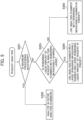
- FIGS. 3 and 5 show a determination flow of request status and processing performance
- FIG. 4 is a diagram showing a screen that manages remaining measurable numbers displayed on the display device
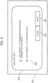
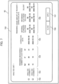
- FIGS. 6 and 7 are diagrams showing a screen that is displayed on the display device and that selects an analysis chamber used in priority.
- the controller 29 selects the analysis chamber 50 to be used for measurement from the two analysis chambers 50 corresponding to the remaining measurable numbers and the measurement request status of the ISE electrodes 1 of the two analysis chambers 50.
- allocation is performed such that the analysis chamber 50 having a largest remaining measurable number is used in priority.
- allocation can be performed using the valid expiration date of the ISE electrode 1. Note that in this case, Step S203 in FIG. 5 , described later, is replaced by the step of "determining whether the valid expiration date of the ISE electrode 1 of the analysis chamber 50 having a large remaining measurable number is longer than the other analysis chamber 50.”
- the controller 29 manages the remaining measurable numbers based on individual identification information read by the reader 1B.
- Step S101 determines whether the maximum processing is necessary.
- Step S102 analysis is executed in all the analysis chambers 50.
- Step S103 the analysis chamber 50 having a large remaining measurable number is used in priority.
- the maximum processing performances of the analysis chambers 50 are set to 300 samples/hour, i.e., 5 samples/minute. Under such conditions, in the case in which the number of samples that have to be processed for two minutes exceeds 20 samples, i.e., 5 samples/(minute ⁇ chamber) ⁇ two chambers ⁇ two minutes, allocation is performed such that both of the two analysis chambers 50 perform processing at the maximum performance.
- the allotment is 8 : 7 and the like
- the analysis chamber 50 having a large remaining measurable number is to perform the maximum processing (ten measurements)
- the analysis chamber 50 having a smaller remaining measurable number is to analyze only five measurements. Note that in the case in which the remaining measurable numbers are almost the same and the like, allotment is equal.
- the remaining measurable number management screen 501 shown in FIG. 4 is displayed on the display device 80.
- the remaining measurable number management screen 501 shown in FIG. 4 is a screen displayed on the display device 80 displaying a chamber display region 503 on which the type of the target analysis chamber 50, a species display region 504 on which the types of ion sensitive membranes are displayed in the ISE electrode 1, a remaining measurement number display region 505 on which the remaining measurement numbers of the ion sensitive membranes are displayed, an expiration date display region 506 on which the expiration date of the ion sensitive membranes is displayed, and a close button 508 that is pressed down when the remaining measurable number management screen 501 is closed. According to such screens, the user can easily grasp which state the analysis chambers 50 presently are.
- the controller 29 selects the analysis chamber 50 used for measurement also based on the remaining liquid amount of the reagent used in the analysis chamber 50.
- an analysis plan is allocated such that the analysis chamber 50 having a large remaining measurable number (the remaining liquid amount or the remaining measurement number) of the reagent is used in priority as well as the remaining measurable number of the ISE electrode 1. Since the initial capacities of the internal standard solution bottle 3, the diluent bottle 4, and the reference electrode solution bottle 5 are known, the remaining measurable number of the reagent can be found by subtracting, from the initial capacity, the used amount that is the number of times of the bottle used for analyzes ⁇ one time.
- Step S201 when it is determined that an analysis request is arrived, the controller 29 determines whether the maximum processing is necessary (Step S201). When it is determined that the maximum processing is necessary, the process goes to Step S202, and analysis is executed in all the analysis chambers 50 (Step S202). In contrast to this, when it is determined that the maximum processing is unnecessary, the process goes to Step S203, and it is determined whether the remaining liquid amount of the reagent of the analysis chamber having a large remaining measurable number is large (Step S203). When it is determined as large, the analysis chamber 50 having a large remaining measurable number with a large remaining liquid amount is used in priority (Step S204).
- the analysis chamber 50 having a large remaining measurable number is used in priority at an allotment about at intermediate in the case in which allotment is equal to the allotment in Step S204 (Step S205).
- the controller 29 selects the analysis chamber 50 used for measurement also based on the sample holding number of the post-analysis buffer 62.
- Step S203 in FIG. 5 is replaced by the step of "determining whether the sample holding number of the post-analysis buffer is a predetermined amount or more."
- the user can select the analysis chamber 50 to be used in priority.
- the analysis chamber selection screen 600 shown in FIG. 6 is a screen that selects whether priority is given to the maximum processing number or priority is given to the expiration date, a check box 602 of an item to which priority is given is checked to press down an apply button 604 for application.
- a close button 605 is pressed down.
- the analysis chamber selection screen 700 shown in FIG. 7 is a screen that selects the analysis chamber 50 with analysis in priority for execution by the user, as a basis for determination whether to give priority, displaying status on a chamber display region 703 on which the type of the target analysis chamber 50 is displayed, an electrode remaining measurable number display region 704 on which the remaining measurement numbers of the ion sensitive membranes is displayed, an expiration date display region 705 on which the expiration date of the ion sensitive membrane is displayed, and a reagent state display region 706 on which the remaining measurable numbers of the reagents and their expiration date are displayed.
- the user checks a check box 702 based on the numerical value to be displayed, and presses down an apply button 707 for application. When the analysis chamber selection screen 700 is closed, a close button 708 is pressed down.
- the above-described electrolyte analyzer 100 includes a plurality of analysis chambers 50 having the ISE electrode 1 that measures the concentration of the electrolyte of the sample and the controller 29 that controls the operation in the electrolyte analyzer 100 including the analysis chamber 50.
- the ISE electrodes 1 of the plurality of analysis chambers 50 analyze the equal analysis item.
- the controller 29 selects the analysis chamber 50 used for measurement from the plurality of analysis chambers 50 corresponding to the remaining measurable numbers and the measurement request status of the plurality of the ISE electrodes 1.
- the analysis chamber 50 to be used is selected corresponding to the remaining measurable numbers, it is possible to give priority to maintaining processing performance when the analysis request status is close to the maximum processing performance to perform the analysis operation.
- the request status is intermitted, it is possible to equalize the remaining measurable number of times of the plurality of analysis chambers 50 with the use of the analysis chamber 50 having a large remaining measurable number in priority.
- the controller 29 determines that the number of measurement requests processed by the electrolyte analyzer 100 within a predetermined time period is less than the maximum processing performance
- the analysis chamber 50 having a largest remaining measurable number is used in priority, and the maximum processing performance is maintained when necessary whereas the remaining measurable numbers are smoothed when unnecessary.
- the controller 29 selects the analysis chamber 50 used for measurement also based on the remaining liquid amount of the reagent used in the analysis chamber 50 in addition to the remaining measurable numbers, and thus it is possible to adjust the replacement frequencies of consumable items in including the reagent, and it is possible to intend to replace consumable items at timing in convenience for the user. For example, it is possible to adjust the replacement of the ISE electrode 1 and the reagent bottle to close and shorten the timing when analysis has to be stopped as short as possible.
- the post-analysis buffer 62 that transports the sample vessel 15 after the completion of the analysis operation to another place is further included.
- the controller 29 selects the analysis chamber 50 used for measurement also based on the sample holding number of the post-analysis buffer 62 in addition to the remaining measurable numbers.
- the ISE electrode 1 has the identification medium 1A that performs individual identification, and further includes the reader 1B that reads individual identification information recorded on the identification medium 1A.
- the controller 29 manages the remaining measurable numbers based on the individual identification information read by the reader 1B, and thus it is possible to automatically execute determination of the remaining measurable numbers on the analyzer side.
- FIG. 8 is a diagram showing the overall structure of the electrolyte analyzer according to the second embodiment
- FIGS. 9 and 10 are diagrams showing a screen that is displayed on the display device of the electrolyte analyzer and that selects a dispensing mechanism used in priority.
- An electrolyte analyzer 100A of the present second embodiment shown in FIG. 8 has a configuration in which in the electrolyte analyzer 100 shown in FIG. 2 , a configuration of the controller 29 and the display device 80 and five configurations related to a unit including the two analysis chambers 50 and transport are included.
- the number of the analysis chambers 50 provided in the unit for analysis is not necessarily two, which can be one or three or more.
- a controller 29 selects a sample probe 14 to be used for dispensing or an analysis chamber 50 used for measurement that is the subsequent stage corresponding to the remaining measurable numbers and the of measurement request status of a plurality of analysis chambers 50.
- a selection can be made whether among five sample probes 14, any of the five sample probes 14 is used for dispensing, i.e., analysis can be performed in any of the analysis units.
- a dispensing mechanism selection screen 800 shown in FIG. 9 can be used.
- the dispensing mechanism selection screen 800 shown in FIG. 9 is a screen that indirectly selects an analysis unit having an analysis chamber 50 that executes analysis in priority by a user by selecting a sample probe 14.
- status is displayed on a dispensing mechanism selection region 802 on which the type of an analysis unit that is a target, an electrode remaining measurable number display region 803 on which the remaining measurement numbers of an ion sensitive membranes is displayed, an expiration date display region 804 on which the expiration date of the ion sensitive membrane is displayed, a reagent remaining measurable number display region 805 on which the remaining measurable numbers of reagents is displayed, and a reagent expiration date display region 806 on which the expiration date of the reagents is displayed.
- the user selects the corresponding analysis unit of the dispensing mechanism selection region 802 based on the numerical value to be displayed to press down an apply button 807 for application. When the dispensing mechanism selection screen 800 is closed, a close button 808 is pressed down.
- the analysis unit used in priority for analysis which is an analysis unit 4 in FIG. 9 , can be displayed with a highlight.
- the number of selectable analysis chamber 50 is not limited specifically, which can be two or more.
- An analysis chamber selection screen 900 shown in FIG. 10 is a screen that selects the analysis chamber 50 with analysis in priority for execution by the user, as a basis for determination whether to give priority, displaying status on a chamber selection region 902 on which the type of the target analysis chamber 50 is displayed, an electrode remaining measurable number display region 903 on which the remaining measurement numbers of the ion sensitive membranes is displayed, an expiration date display region 904 on which the expiration date of an ion sensitive membrane is displayed, a reagent remaining measurable number display region 905 on which the remaining measurable numbers of reagents is displayed, and a reagent expiration date display region 906 on which the expiration date of the reagent is displayed.
- the user selects the corresponding analysis unit of the chamber selection region 902 based on the numerical value to be displayed to press down an apply button 907 is pressed down for application.
- a close button 908 is pressed down.
- the analysis units used in priority for analysis which are an analysis chamber 1 of an analysis unit 2, an analysis chamber 2 of an analysis unit 3, and an analysis chamber 1 of an analysis unit 4 in FIG. 10 , can be displayed with a highlight.
- the plurality of analysis chambers 50 shares the sample probe 14 that dispenses a sample to the analysis chamber 50.
- the controller 29 selects the sample probe 14 to be used for dispensing and the analysis chamber 50 used for measurement corresponding to the remaining measurable numbers and the of measurement request status of the plurality of analysis chambers 50, and thus it is possible to optimize a module to be used corresponding to the remaining measurable numbers of consumable items in units of a module. Accordingly, also in the entire system, management is possible such as unifying the replacement frequency (or divided into two systems).
Landscapes
- General Health & Medical Sciences (AREA)
- Health & Medical Sciences (AREA)
- Immunology (AREA)
- Pathology (AREA)
- Analytical Chemistry (AREA)
- Biochemistry (AREA)
- Life Sciences & Earth Sciences (AREA)
- General Physics & Mathematics (AREA)
- Physics & Mathematics (AREA)
- Chemical & Material Sciences (AREA)
- Engineering & Computer Science (AREA)
- Epidemiology (AREA)
- Medical Informatics (AREA)
- Primary Health Care (AREA)
- Public Health (AREA)
- Automatic Analysis And Handling Materials Therefor (AREA)
Applications Claiming Priority (2)
| Application Number | Priority Date | Filing Date | Title |
|---|---|---|---|
| JP2020122088 | 2020-07-16 | ||
| PCT/JP2021/009801 WO2022014096A1 (ja) | 2020-07-16 | 2021-03-11 | 電解質分析装置 |
Publications (3)
| Publication Number | Publication Date |
|---|---|
| EP4184174A1 EP4184174A1 (en) | 2023-05-24 |
| EP4184174A4 EP4184174A4 (en) | 2024-07-31 |
| EP4184174B1 true EP4184174B1 (en) | 2025-03-05 |
Family
ID=79554640
Family Applications (1)
| Application Number | Title | Priority Date | Filing Date |
|---|---|---|---|
| EP21841428.2A Active EP4184174B1 (en) | 2020-07-16 | 2021-03-11 | Electrolyte analysis device |
Country Status (5)
| Country | Link |
|---|---|
| US (1) | US12385935B2 (https=) |
| EP (1) | EP4184174B1 (https=) |
| JP (1) | JP7391224B2 (https=) |
| CN (1) | CN115769081B (https=) |
| WO (1) | WO2022014096A1 (https=) |
Families Citing this family (1)
| Publication number | Priority date | Publication date | Assignee | Title |
|---|---|---|---|---|
| CN120548477A (zh) | 2023-05-30 | 2025-08-26 | 株式会社日立高新技术 | 自动分析装置以及分析槽的分配方法 |
Family Cites Families (10)
| Publication number | Priority date | Publication date | Assignee | Title |
|---|---|---|---|---|
| US4649028A (en) * | 1985-03-27 | 1987-03-10 | Medica Corporation | Electrolyte analyzer |
| JP4934449B2 (ja) * | 2007-02-02 | 2012-05-16 | ベックマン コールター, インコーポレイテッド | 分析装置 |
| JP2010151672A (ja) * | 2008-12-25 | 2010-07-08 | Beckman Coulter Inc | 自動分析装置 |
| JP5358336B2 (ja) * | 2009-07-31 | 2013-12-04 | 株式会社日立ハイテクノロジーズ | 自動分析装置 |
| JP5378962B2 (ja) | 2009-11-26 | 2013-12-25 | 株式会社日立ハイテクノロジーズ | 動的搬送計画装置及び動的搬送計画方法 |
| JP2012189405A (ja) | 2011-03-10 | 2012-10-04 | Jeol Ltd | 電解質測定方法及び電解質測定装置 |
| JP6177532B2 (ja) * | 2013-01-23 | 2017-08-09 | 株式会社日立ハイテクノロジーズ | 自動分析システムおよび制御方法 |
| JP6161909B2 (ja) * | 2013-01-29 | 2017-07-12 | 株式会社日立ハイテクノロジーズ | 自動分析装置 |
| JP6260317B2 (ja) * | 2014-02-06 | 2018-01-17 | コニカミノルタ株式会社 | イムノアッセイ装置およびイムノアッセイ法 |
| US12123884B2 (en) * | 2018-12-11 | 2024-10-22 | Hitachi High-Tech Corporation | Monitoring the cleaning status of an automatic analyzer |
-
2021
- 2021-03-11 EP EP21841428.2A patent/EP4184174B1/en active Active
- 2021-03-11 JP JP2022536130A patent/JP7391224B2/ja active Active
- 2021-03-11 WO PCT/JP2021/009801 patent/WO2022014096A1/ja not_active Ceased
- 2021-03-11 US US18/015,971 patent/US12385935B2/en active Active
- 2021-03-11 CN CN202180045584.2A patent/CN115769081B/zh active Active
Also Published As
| Publication number | Publication date |
|---|---|
| US20230288439A1 (en) | 2023-09-14 |
| CN115769081B (zh) | 2025-11-18 |
| JP7391224B2 (ja) | 2023-12-04 |
| EP4184174A4 (en) | 2024-07-31 |
| US12385935B2 (en) | 2025-08-12 |
| EP4184174A1 (en) | 2023-05-24 |
| JPWO2022014096A1 (https=) | 2022-01-20 |
| WO2022014096A1 (ja) | 2022-01-20 |
| CN115769081A (zh) | 2023-03-07 |
Similar Documents
| Publication | Publication Date | Title |
|---|---|---|
| JP7602524B2 (ja) | 自動分析装置及び自動分析方法 | |
| EP1975624B1 (en) | Automatic analyzer | |
| EP3176585B1 (en) | Automatic analysis apparatus | |
| US20210025911A1 (en) | Automatic analysis device | |
| JP7144667B2 (ja) | 自動分析装置および自動分析システム、ならびに試料の自動分析方法 | |
| EP4184174B1 (en) | Electrolyte analysis device | |
| EP4024050B1 (en) | Automated analyzer | |
| EP4033254A1 (en) | Automated analysis device | |
| US12332209B2 (en) | Electrolyte analysis device | |
| US11579159B2 (en) | Automatic analysis device | |
| JP7378477B2 (ja) | 自動分析装置および試料の自動分析方法 | |
| EP3961225B1 (en) | Automated analysis device | |
| US20230152343A1 (en) | Laboratory instrument | |
| CN117616283A (zh) | 自动分析装置以及自动分析装置的试剂管理方法 | |
| US20240125735A1 (en) | Electrolyte measurement device and method for determining abnormality of electrolyte concentration measurement unit | |
| WO2025220386A1 (ja) | 電解質分析装置、制御方法 |
Legal Events
| Date | Code | Title | Description |
|---|---|---|---|
| STAA | Information on the status of an ep patent application or granted ep patent |
Free format text: STATUS: THE INTERNATIONAL PUBLICATION HAS BEEN MADE |
|
| PUAI | Public reference made under article 153(3) epc to a published international application that has entered the european phase |
Free format text: ORIGINAL CODE: 0009012 |
|
| STAA | Information on the status of an ep patent application or granted ep patent |
Free format text: STATUS: REQUEST FOR EXAMINATION WAS MADE |
|
| 17P | Request for examination filed |
Effective date: 20221221 |
|
| AK | Designated contracting states |
Kind code of ref document: A1 Designated state(s): AL AT BE BG CH CY CZ DE DK EE ES FI FR GB GR HR HU IE IS IT LI LT LU LV MC MK MT NL NO PL PT RO RS SE SI SK SM TR |
|
| DAV | Request for validation of the european patent (deleted) | ||
| DAX | Request for extension of the european patent (deleted) | ||
| REG | Reference to a national code |
Ref country code: DE Ref legal event code: R079 Free format text: PREVIOUS MAIN CLASS: G01N0035020000 Ipc: G01N0035000000 Ref document number: 602021027293 Country of ref document: DE |
|
| A4 | Supplementary search report drawn up and despatched |
Effective date: 20240628 |
|
| RIC1 | Information provided on ipc code assigned before grant |
Ipc: G01N 33/49 20060101ALI20240624BHEP Ipc: G16H 10/40 20180101ALI20240624BHEP Ipc: G01N 27/416 20060101ALI20240624BHEP Ipc: G01N 35/10 20060101ALI20240624BHEP Ipc: G01N 35/00 20060101AFI20240624BHEP |
|
| GRAP | Despatch of communication of intention to grant a patent |
Free format text: ORIGINAL CODE: EPIDOSNIGR1 |
|
| STAA | Information on the status of an ep patent application or granted ep patent |
Free format text: STATUS: GRANT OF PATENT IS INTENDED |
|
| RIC1 | Information provided on ipc code assigned before grant |
Ipc: G01N 33/49 20060101ALI20241127BHEP Ipc: G16H 10/40 20180101ALI20241127BHEP Ipc: G01N 27/416 20060101ALI20241127BHEP Ipc: G01N 35/10 20060101ALI20241127BHEP Ipc: G01N 35/00 20060101AFI20241127BHEP |
|
| INTG | Intention to grant announced |
Effective date: 20241205 |
|
| GRAS | Grant fee paid |
Free format text: ORIGINAL CODE: EPIDOSNIGR3 |
|
| GRAA | (expected) grant |
Free format text: ORIGINAL CODE: 0009210 |
|
| STAA | Information on the status of an ep patent application or granted ep patent |
Free format text: STATUS: THE PATENT HAS BEEN GRANTED |
|
| AK | Designated contracting states |
Kind code of ref document: B1 Designated state(s): AL AT BE BG CH CY CZ DE DK EE ES FI FR GB GR HR HU IE IS IT LI LT LU LV MC MK MT NL NO PL PT RO RS SE SI SK SM TR |
|
| REG | Reference to a national code |
Ref country code: GB Ref legal event code: FG4D |
|
| REG | Reference to a national code |
Ref country code: CH Ref legal event code: EP |
|
| REG | Reference to a national code |
Ref country code: IE Ref legal event code: FG4D |
|
| REG | Reference to a national code |
Ref country code: DE Ref legal event code: R096 Ref document number: 602021027293 Country of ref document: DE |
|
| PGFP | Annual fee paid to national office [announced via postgrant information from national office to epo] |
Ref country code: AT Payment date: 20250417 Year of fee payment: 5 |
|
| PG25 | Lapsed in a contracting state [announced via postgrant information from national office to epo] |
Ref country code: RS Free format text: LAPSE BECAUSE OF FAILURE TO SUBMIT A TRANSLATION OF THE DESCRIPTION OR TO PAY THE FEE WITHIN THE PRESCRIBED TIME-LIMIT Effective date: 20250605 |
|
| PG25 | Lapsed in a contracting state [announced via postgrant information from national office to epo] |
Ref country code: FI Free format text: LAPSE BECAUSE OF FAILURE TO SUBMIT A TRANSLATION OF THE DESCRIPTION OR TO PAY THE FEE WITHIN THE PRESCRIBED TIME-LIMIT Effective date: 20250305 |
|
| REG | Reference to a national code |
Ref country code: NL Ref legal event code: MP Effective date: 20250305 |
|
| PG25 | Lapsed in a contracting state [announced via postgrant information from national office to epo] |
Ref country code: ES Free format text: LAPSE BECAUSE OF FAILURE TO SUBMIT A TRANSLATION OF THE DESCRIPTION OR TO PAY THE FEE WITHIN THE PRESCRIBED TIME-LIMIT Effective date: 20250305 |
|
| REG | Reference to a national code |
Ref country code: LT Ref legal event code: MG9D |
|
| PG25 | Lapsed in a contracting state [announced via postgrant information from national office to epo] |
Ref country code: NO Free format text: LAPSE BECAUSE OF FAILURE TO SUBMIT A TRANSLATION OF THE DESCRIPTION OR TO PAY THE FEE WITHIN THE PRESCRIBED TIME-LIMIT Effective date: 20250605 |
|
| PG25 | Lapsed in a contracting state [announced via postgrant information from national office to epo] |
Ref country code: HR Free format text: LAPSE BECAUSE OF FAILURE TO SUBMIT A TRANSLATION OF THE DESCRIPTION OR TO PAY THE FEE WITHIN THE PRESCRIBED TIME-LIMIT Effective date: 20250305 |
|
| PG25 | Lapsed in a contracting state [announced via postgrant information from national office to epo] |
Ref country code: LV Free format text: LAPSE BECAUSE OF FAILURE TO SUBMIT A TRANSLATION OF THE DESCRIPTION OR TO PAY THE FEE WITHIN THE PRESCRIBED TIME-LIMIT Effective date: 20250305 |
|
| PG25 | Lapsed in a contracting state [announced via postgrant information from national office to epo] |
Ref country code: BG Free format text: LAPSE BECAUSE OF FAILURE TO SUBMIT A TRANSLATION OF THE DESCRIPTION OR TO PAY THE FEE WITHIN THE PRESCRIBED TIME-LIMIT Effective date: 20250305 Ref country code: GR Free format text: LAPSE BECAUSE OF FAILURE TO SUBMIT A TRANSLATION OF THE DESCRIPTION OR TO PAY THE FEE WITHIN THE PRESCRIBED TIME-LIMIT Effective date: 20250606 |
|
| REG | Reference to a national code |
Ref country code: AT Ref legal event code: MK05 Ref document number: 1773355 Country of ref document: AT Kind code of ref document: T Effective date: 20250305 |
|
| PG25 | Lapsed in a contracting state [announced via postgrant information from national office to epo] |
Ref country code: NL Free format text: LAPSE BECAUSE OF FAILURE TO SUBMIT A TRANSLATION OF THE DESCRIPTION OR TO PAY THE FEE WITHIN THE PRESCRIBED TIME-LIMIT Effective date: 20250305 |
|
| PG25 | Lapsed in a contracting state [announced via postgrant information from national office to epo] |
Ref country code: SE Free format text: LAPSE BECAUSE OF FAILURE TO SUBMIT A TRANSLATION OF THE DESCRIPTION OR TO PAY THE FEE WITHIN THE PRESCRIBED TIME-LIMIT Effective date: 20250305 |
|
| PG25 | Lapsed in a contracting state [announced via postgrant information from national office to epo] |
Ref country code: SM Free format text: LAPSE BECAUSE OF FAILURE TO SUBMIT A TRANSLATION OF THE DESCRIPTION OR TO PAY THE FEE WITHIN THE PRESCRIBED TIME-LIMIT Effective date: 20250305 |
|
| PG25 | Lapsed in a contracting state [announced via postgrant information from national office to epo] |
Ref country code: PT Free format text: LAPSE BECAUSE OF FAILURE TO SUBMIT A TRANSLATION OF THE DESCRIPTION OR TO PAY THE FEE WITHIN THE PRESCRIBED TIME-LIMIT Effective date: 20250707 |
|
| PG25 | Lapsed in a contracting state [announced via postgrant information from national office to epo] |
Ref country code: PL Free format text: LAPSE BECAUSE OF FAILURE TO SUBMIT A TRANSLATION OF THE DESCRIPTION OR TO PAY THE FEE WITHIN THE PRESCRIBED TIME-LIMIT Effective date: 20250305 Ref country code: IT Free format text: LAPSE BECAUSE OF FAILURE TO SUBMIT A TRANSLATION OF THE DESCRIPTION OR TO PAY THE FEE WITHIN THE PRESCRIBED TIME-LIMIT Effective date: 20250305 |
|
| PG25 | Lapsed in a contracting state [announced via postgrant information from national office to epo] |
Ref country code: AT Free format text: LAPSE BECAUSE OF FAILURE TO SUBMIT A TRANSLATION OF THE DESCRIPTION OR TO PAY THE FEE WITHIN THE PRESCRIBED TIME-LIMIT Effective date: 20250305 |
|
| PG25 | Lapsed in a contracting state [announced via postgrant information from national office to epo] |
Ref country code: EE Free format text: LAPSE BECAUSE OF FAILURE TO SUBMIT A TRANSLATION OF THE DESCRIPTION OR TO PAY THE FEE WITHIN THE PRESCRIBED TIME-LIMIT Effective date: 20250305 Ref country code: CZ Free format text: LAPSE BECAUSE OF FAILURE TO SUBMIT A TRANSLATION OF THE DESCRIPTION OR TO PAY THE FEE WITHIN THE PRESCRIBED TIME-LIMIT Effective date: 20250305 |
|
| PG25 | Lapsed in a contracting state [announced via postgrant information from national office to epo] |
Ref country code: RO Free format text: LAPSE BECAUSE OF FAILURE TO SUBMIT A TRANSLATION OF THE DESCRIPTION OR TO PAY THE FEE WITHIN THE PRESCRIBED TIME-LIMIT Effective date: 20250305 |
|
| REG | Reference to a national code |
Ref country code: CH Ref legal event code: H13 Free format text: ST27 STATUS EVENT CODE: U-0-0-H10-H13 (AS PROVIDED BY THE NATIONAL OFFICE) Effective date: 20251023 |
|
| PG25 | Lapsed in a contracting state [announced via postgrant information from national office to epo] |
Ref country code: SK Free format text: LAPSE BECAUSE OF FAILURE TO SUBMIT A TRANSLATION OF THE DESCRIPTION OR TO PAY THE FEE WITHIN THE PRESCRIBED TIME-LIMIT Effective date: 20250305 |
|
| PG25 | Lapsed in a contracting state [announced via postgrant information from national office to epo] |
Ref country code: IS Free format text: LAPSE BECAUSE OF FAILURE TO SUBMIT A TRANSLATION OF THE DESCRIPTION OR TO PAY THE FEE WITHIN THE PRESCRIBED TIME-LIMIT Effective date: 20250705 |
|
| PG25 | Lapsed in a contracting state [announced via postgrant information from national office to epo] |
Ref country code: LU Free format text: LAPSE BECAUSE OF NON-PAYMENT OF DUE FEES Effective date: 20250311 |
|
| REG | Reference to a national code |
Ref country code: DE Ref legal event code: R097 Ref document number: 602021027293 Country of ref document: DE |
|
| REG | Reference to a national code |
Ref country code: BE Ref legal event code: MM Effective date: 20250331 |
|
| PG25 | Lapsed in a contracting state [announced via postgrant information from national office to epo] |
Ref country code: MC Free format text: LAPSE BECAUSE OF FAILURE TO SUBMIT A TRANSLATION OF THE DESCRIPTION OR TO PAY THE FEE WITHIN THE PRESCRIBED TIME-LIMIT Effective date: 20250305 |
|
| PLBE | No opposition filed within time limit |
Free format text: ORIGINAL CODE: 0009261 |
|
| STAA | Information on the status of an ep patent application or granted ep patent |
Free format text: STATUS: NO OPPOSITION FILED WITHIN TIME LIMIT |
|
| PG25 | Lapsed in a contracting state [announced via postgrant information from national office to epo] |
Ref country code: DK Free format text: LAPSE BECAUSE OF FAILURE TO SUBMIT A TRANSLATION OF THE DESCRIPTION OR TO PAY THE FEE WITHIN THE PRESCRIBED TIME-LIMIT Effective date: 20250305 |
|
| REG | Reference to a national code |
Ref country code: CH Ref legal event code: L10 Free format text: ST27 STATUS EVENT CODE: U-0-0-L10-L00 (AS PROVIDED BY THE NATIONAL OFFICE) Effective date: 20260114 |
|
| PG25 | Lapsed in a contracting state [announced via postgrant information from national office to epo] |
Ref country code: BE Free format text: LAPSE BECAUSE OF NON-PAYMENT OF DUE FEES Effective date: 20250331 |
|
| PG25 | Lapsed in a contracting state [announced via postgrant information from national office to epo] |
Ref country code: CH Free format text: LAPSE BECAUSE OF NON-PAYMENT OF DUE FEES Effective date: 20250331 |
|
| PG25 | Lapsed in a contracting state [announced via postgrant information from national office to epo] |
Ref country code: IE Free format text: LAPSE BECAUSE OF NON-PAYMENT OF DUE FEES Effective date: 20250311 |
|
| 26N | No opposition filed |
Effective date: 20251208 |
|
| GBPC | Gb: european patent ceased through non-payment of renewal fee |
Effective date: 20250605 |
|
| PG25 | Lapsed in a contracting state [announced via postgrant information from national office to epo] |
Ref country code: GB Free format text: LAPSE BECAUSE OF NON-PAYMENT OF DUE FEES Effective date: 20250605 |
|
| PGFP | Annual fee paid to national office [announced via postgrant information from national office to epo] |
Ref country code: DE Payment date: 20260324 Year of fee payment: 6 |
|
| PGFP | Annual fee paid to national office [announced via postgrant information from national office to epo] |
Ref country code: FR Payment date: 20260323 Year of fee payment: 6 |