EP4184105A1 - Heat exchanger - Google Patents
Heat exchanger Download PDFInfo
- Publication number
- EP4184105A1 EP4184105A1 EP21841525.5A EP21841525A EP4184105A1 EP 4184105 A1 EP4184105 A1 EP 4184105A1 EP 21841525 A EP21841525 A EP 21841525A EP 4184105 A1 EP4184105 A1 EP 4184105A1
- Authority
- EP
- European Patent Office
- Prior art keywords
- heat transfer
- transfer tube
- heat
- heat exchanger
- region
- Prior art date
- Legal status (The legal status is an assumption and is not a legal conclusion. Google has not performed a legal analysis and makes no representation as to the accuracy of the status listed.)
- Granted
Links
Images









Classifications
-
- F—MECHANICAL ENGINEERING; LIGHTING; HEATING; WEAPONS; BLASTING
- F28—HEAT EXCHANGE IN GENERAL
- F28D—HEAT-EXCHANGE APPARATUS, NOT PROVIDED FOR IN ANOTHER SUBCLASS, IN WHICH THE HEAT-EXCHANGE MEDIA DO NOT COME INTO DIRECT CONTACT
- F28D7/00—Heat-exchange apparatus having stationary tubular conduit assemblies for both heat-exchange media, the media being in contact with different sides of a conduit wall
- F28D7/16—Heat-exchange apparatus having stationary tubular conduit assemblies for both heat-exchange media, the media being in contact with different sides of a conduit wall the conduits being arranged in parallel spaced relation
-
- F—MECHANICAL ENGINEERING; LIGHTING; HEATING; WEAPONS; BLASTING
- F28—HEAT EXCHANGE IN GENERAL
- F28D—HEAT-EXCHANGE APPARATUS, NOT PROVIDED FOR IN ANOTHER SUBCLASS, IN WHICH THE HEAT-EXCHANGE MEDIA DO NOT COME INTO DIRECT CONTACT
- F28D1/00—Heat-exchange apparatus having stationary conduit assemblies for one heat-exchange medium only, the media being in contact with different sides of the conduit wall, in which the other heat-exchange medium is a large body of fluid, e.g. domestic or motor car radiators
- F28D1/02—Heat-exchange apparatus having stationary conduit assemblies for one heat-exchange medium only, the media being in contact with different sides of the conduit wall, in which the other heat-exchange medium is a large body of fluid, e.g. domestic or motor car radiators with heat-exchange conduits immersed in the body of fluid
- F28D1/04—Heat-exchange apparatus having stationary conduit assemblies for one heat-exchange medium only, the media being in contact with different sides of the conduit wall, in which the other heat-exchange medium is a large body of fluid, e.g. domestic or motor car radiators with heat-exchange conduits immersed in the body of fluid with tubular conduits
- F28D1/053—Heat-exchange apparatus having stationary conduit assemblies for one heat-exchange medium only, the media being in contact with different sides of the conduit wall, in which the other heat-exchange medium is a large body of fluid, e.g. domestic or motor car radiators with heat-exchange conduits immersed in the body of fluid with tubular conduits the conduits being straight
- F28D1/0535—Heat-exchange apparatus having stationary conduit assemblies for one heat-exchange medium only, the media being in contact with different sides of the conduit wall, in which the other heat-exchange medium is a large body of fluid, e.g. domestic or motor car radiators with heat-exchange conduits immersed in the body of fluid with tubular conduits the conduits being straight the conduits having a non-circular cross-section
- F28D1/05366—Assemblies of conduits connected to common headers, e.g. core type radiators
- F28D1/05383—Assemblies of conduits connected to common headers, e.g. core type radiators with multiple rows of conduits or with multi-channel conduits
-
- B—PERFORMING OPERATIONS; TRANSPORTING
- B21—MECHANICAL METAL-WORKING WITHOUT ESSENTIALLY REMOVING MATERIAL; PUNCHING METAL
- B21D—WORKING OR PROCESSING OF SHEET METAL OR METAL TUBES, RODS OR PROFILES WITHOUT ESSENTIALLY REMOVING MATERIAL; PUNCHING METAL
- B21D22/00—Shaping without cutting, by stamping, spinning, or deep-drawing
- B21D22/20—Deep-drawing
-
- B—PERFORMING OPERATIONS; TRANSPORTING
- B21—MECHANICAL METAL-WORKING WITHOUT ESSENTIALLY REMOVING MATERIAL; PUNCHING METAL
- B21D—WORKING OR PROCESSING OF SHEET METAL OR METAL TUBES, RODS OR PROFILES WITHOUT ESSENTIALLY REMOVING MATERIAL; PUNCHING METAL
- B21D53/00—Making other particular articles
- B21D53/02—Making other particular articles heat exchangers or parts thereof, e.g. radiators, condensers fins, headers
- B21D53/06—Making other particular articles heat exchangers or parts thereof, e.g. radiators, condensers fins, headers of metal tubes
-
- F—MECHANICAL ENGINEERING; LIGHTING; HEATING; WEAPONS; BLASTING
- F25—REFRIGERATION OR COOLING; COMBINED HEATING AND REFRIGERATION SYSTEMS; HEAT PUMP SYSTEMS; MANUFACTURE OR STORAGE OF ICE; LIQUEFACTION SOLIDIFICATION OF GASES
- F25B—REFRIGERATION MACHINES, PLANTS OR SYSTEMS; COMBINED HEATING AND REFRIGERATION SYSTEMS; HEAT PUMP SYSTEMS
- F25B39/00—Evaporators; Condensers
- F25B39/02—Evaporators
-
- F—MECHANICAL ENGINEERING; LIGHTING; HEATING; WEAPONS; BLASTING
- F28—HEAT EXCHANGE IN GENERAL
- F28D—HEAT-EXCHANGE APPARATUS, NOT PROVIDED FOR IN ANOTHER SUBCLASS, IN WHICH THE HEAT-EXCHANGE MEDIA DO NOT COME INTO DIRECT CONTACT
- F28D1/00—Heat-exchange apparatus having stationary conduit assemblies for one heat-exchange medium only, the media being in contact with different sides of the conduit wall, in which the other heat-exchange medium is a large body of fluid, e.g. domestic or motor car radiators
- F28D1/02—Heat-exchange apparatus having stationary conduit assemblies for one heat-exchange medium only, the media being in contact with different sides of the conduit wall, in which the other heat-exchange medium is a large body of fluid, e.g. domestic or motor car radiators with heat-exchange conduits immersed in the body of fluid
- F28D1/0246—Heat-exchange apparatus having stationary conduit assemblies for one heat-exchange medium only, the media being in contact with different sides of the conduit wall, in which the other heat-exchange medium is a large body of fluid, e.g. domestic or motor car radiators with heat-exchange conduits immersed in the body of fluid heat-exchange elements having several adjacent conduits forming a whole, e.g. blocks
-
- F—MECHANICAL ENGINEERING; LIGHTING; HEATING; WEAPONS; BLASTING
- F28—HEAT EXCHANGE IN GENERAL
- F28F—DETAILS OF HEAT-EXCHANGE AND HEAT-TRANSFER APPARATUS, OF GENERAL APPLICATION
- F28F1/00—Tubular elements; Assemblies of tubular elements
- F28F1/02—Tubular elements of cross-section which is non-circular
- F28F1/022—Tubular elements of cross-section which is non-circular with multiple channels
-
- F—MECHANICAL ENGINEERING; LIGHTING; HEATING; WEAPONS; BLASTING
- F28—HEAT EXCHANGE IN GENERAL
- F28F—DETAILS OF HEAT-EXCHANGE AND HEAT-TRANSFER APPARATUS, OF GENERAL APPLICATION
- F28F1/00—Tubular elements; Assemblies of tubular elements
- F28F1/02—Tubular elements of cross-section which is non-circular
- F28F1/025—Tubular elements of cross-section which is non-circular with variable shape, e.g. with modified tube ends, with different geometrical features
-
- F—MECHANICAL ENGINEERING; LIGHTING; HEATING; WEAPONS; BLASTING
- F28—HEAT EXCHANGE IN GENERAL
- F28F—DETAILS OF HEAT-EXCHANGE AND HEAT-TRANSFER APPARATUS, OF GENERAL APPLICATION
- F28F1/00—Tubular elements; Assemblies of tubular elements
- F28F1/02—Tubular elements of cross-section which is non-circular
- F28F1/04—Tubular elements of cross-section which is non-circular polygonal, e.g. rectangular
-
- F—MECHANICAL ENGINEERING; LIGHTING; HEATING; WEAPONS; BLASTING
- F28—HEAT EXCHANGE IN GENERAL
- F28F—DETAILS OF HEAT-EXCHANGE AND HEAT-TRANSFER APPARATUS, OF GENERAL APPLICATION
- F28F1/00—Tubular elements; Assemblies of tubular elements
- F28F1/08—Tubular elements crimped or corrugated in longitudinal section
-
- F—MECHANICAL ENGINEERING; LIGHTING; HEATING; WEAPONS; BLASTING
- F28—HEAT EXCHANGE IN GENERAL
- F28F—DETAILS OF HEAT-EXCHANGE AND HEAT-TRANSFER APPARATUS, OF GENERAL APPLICATION
- F28F1/00—Tubular elements; Assemblies of tubular elements
- F28F1/10—Tubular elements and assemblies thereof with means for increasing heat-transfer area, e.g. with fins, with projections, with recesses
- F28F1/12—Tubular elements and assemblies thereof with means for increasing heat-transfer area, e.g. with fins, with projections, with recesses the means being only outside the tubular element
- F28F1/24—Tubular elements and assemblies thereof with means for increasing heat-transfer area, e.g. with fins, with projections, with recesses the means being only outside the tubular element and extending transversely
- F28F1/26—Tubular elements and assemblies thereof with means for increasing heat-transfer area, e.g. with fins, with projections, with recesses the means being only outside the tubular element and extending transversely the means being integral with the element
-
- F—MECHANICAL ENGINEERING; LIGHTING; HEATING; WEAPONS; BLASTING
- F28—HEAT EXCHANGE IN GENERAL
- F28F—DETAILS OF HEAT-EXCHANGE AND HEAT-TRANSFER APPARATUS, OF GENERAL APPLICATION
- F28F1/00—Tubular elements; Assemblies of tubular elements
- F28F1/10—Tubular elements and assemblies thereof with means for increasing heat-transfer area, e.g. with fins, with projections, with recesses
- F28F1/42—Tubular elements and assemblies thereof with means for increasing heat-transfer area, e.g. with fins, with projections, with recesses the means being both outside and inside the tubular element
- F28F1/424—Means comprising outside portions integral with inside portions
- F28F1/426—Means comprising outside portions integral with inside portions the outside portions and the inside portions forming parts of complementary shape, e.g. concave and convex
-
- F—MECHANICAL ENGINEERING; LIGHTING; HEATING; WEAPONS; BLASTING
- F28—HEAT EXCHANGE IN GENERAL
- F28F—DETAILS OF HEAT-EXCHANGE AND HEAT-TRANSFER APPARATUS, OF GENERAL APPLICATION
- F28F13/00—Arrangements for modifying heat-transfer, e.g. increasing, decreasing
- F28F13/06—Arrangements for modifying heat-transfer, e.g. increasing, decreasing by affecting the pattern of flow of the heat-exchange media
- F28F13/08—Arrangements for modifying heat-transfer, e.g. increasing, decreasing by affecting the pattern of flow of the heat-exchange media by varying the cross-section of the flow channels
-
- F—MECHANICAL ENGINEERING; LIGHTING; HEATING; WEAPONS; BLASTING
- F28—HEAT EXCHANGE IN GENERAL
- F28F—DETAILS OF HEAT-EXCHANGE AND HEAT-TRANSFER APPARATUS, OF GENERAL APPLICATION
- F28F19/00—Preventing the formation of deposits or corrosion, e.g. by using filters or scrapers
- F28F19/006—Preventing deposits of ice
-
- F—MECHANICAL ENGINEERING; LIGHTING; HEATING; WEAPONS; BLASTING
- F28—HEAT EXCHANGE IN GENERAL
- F28F—DETAILS OF HEAT-EXCHANGE AND HEAT-TRANSFER APPARATUS, OF GENERAL APPLICATION
- F28F9/00—Casings; Header boxes; Auxiliary supports for elements; Auxiliary members within casings
- F28F9/02—Header boxes; End plates
-
- H—ELECTRICITY
- H05—ELECTRIC TECHNIQUES NOT OTHERWISE PROVIDED FOR
- H05B—ELECTRIC HEATING; ELECTRIC LIGHT SOURCES NOT OTHERWISE PROVIDED FOR; CIRCUIT ARRANGEMENTS FOR ELECTRIC LIGHT SOURCES, IN GENERAL
- H05B6/00—Heating by electric, magnetic or electromagnetic fields
- H05B6/02—Induction heating
- H05B6/10—Induction heating apparatus, other than furnaces, for specific applications
- H05B6/101—Induction heating apparatus, other than furnaces, for specific applications for local heating of metal pieces
-
- F—MECHANICAL ENGINEERING; LIGHTING; HEATING; WEAPONS; BLASTING
- F25—REFRIGERATION OR COOLING; COMBINED HEATING AND REFRIGERATION SYSTEMS; HEAT PUMP SYSTEMS; MANUFACTURE OR STORAGE OF ICE; LIQUEFACTION SOLIDIFICATION OF GASES
- F25B—REFRIGERATION MACHINES, PLANTS OR SYSTEMS; COMBINED HEATING AND REFRIGERATION SYSTEMS; HEAT PUMP SYSTEMS
- F25B13/00—Compression machines, plants or systems, with reversible cycle
-
- F—MECHANICAL ENGINEERING; LIGHTING; HEATING; WEAPONS; BLASTING
- F25—REFRIGERATION OR COOLING; COMBINED HEATING AND REFRIGERATION SYSTEMS; HEAT PUMP SYSTEMS; MANUFACTURE OR STORAGE OF ICE; LIQUEFACTION SOLIDIFICATION OF GASES
- F25B—REFRIGERATION MACHINES, PLANTS OR SYSTEMS; COMBINED HEATING AND REFRIGERATION SYSTEMS; HEAT PUMP SYSTEMS
- F25B39/00—Evaporators; Condensers
- F25B39/04—Condensers
-
- F—MECHANICAL ENGINEERING; LIGHTING; HEATING; WEAPONS; BLASTING
- F28—HEAT EXCHANGE IN GENERAL
- F28D—HEAT-EXCHANGE APPARATUS, NOT PROVIDED FOR IN ANOTHER SUBCLASS, IN WHICH THE HEAT-EXCHANGE MEDIA DO NOT COME INTO DIRECT CONTACT
- F28D21/00—Heat-exchange apparatus not covered by any of the groups F28D1/00 - F28D20/00
- F28D2021/0019—Other heat exchangers for particular applications; Heat exchange systems not otherwise provided for
- F28D2021/0068—Other heat exchangers for particular applications; Heat exchange systems not otherwise provided for for refrigerant cycles
-
- F—MECHANICAL ENGINEERING; LIGHTING; HEATING; WEAPONS; BLASTING
- F28—HEAT EXCHANGE IN GENERAL
- F28F—DETAILS OF HEAT-EXCHANGE AND HEAT-TRANSFER APPARATUS, OF GENERAL APPLICATION
- F28F2215/00—Fins
- F28F2215/04—Assemblies of fins having different features, e.g. with different fin densities
Definitions
- the present disclosure relates to a heat exchanger, and more particularly, to a heat exchanger that does not have heat transfer fins.
- Patent Literature 1 International Publication No. 2005/073655 discloses a heat exchanger, without no heat transfer fins, in which a plurality of refrigerant channels extending in a first direction is arranged in a third direction and a plurality of flat heat transfer tubes is arranged in a second direction orthogonal to the first direction and the third direction.
- each of the heat transfer tubes is configured to have a concave and convex shape along the third direction when the heat transfer tube is viewed along the first direction so that the heat transfer efficiency may be improved.
- a heat exchanger is a heat exchanger including a plurality of refrigerant channels extending in a first direction, and the plurality of refrigerant channels is arranged along a second direction intersecting with the first direction and is arranged along a third direction intersecting with the first direction and the second direction.
- the heat exchanger includes a plurality of heat transfer tubes defining the refrigerant channels. At least one of a size of an outer edge or a size of an inner edge of the heat transfer tube is different between a first position and a second position in the first direction.
- At least one of the sizes of the outer edge or the inner edge of the heat transfer tube is changed along the first direction, i.e., along the refrigerant channel. It is therefore possible to improve the efficiency of the heat exchanger in accordance with the state change of the refrigerant in each refrigerant channel.
- a heat exchanger according to a second aspect is the heat exchanger according to the first aspect, wherein the heat transfer tubes are flat multi-hole tubes defining the plurality of refrigerant channels arranged along the third direction.
- the use of the flat multi-hole tube as the heat transfer tube may achieve efficient heat exchange between the refrigerant and the external fluid without using heat transfer fins.
- a heat exchanger according to a third aspect is the heat exchanger according to the first aspect or the second aspect, wherein the first direction is a vertical direction.
- a heat exchanger is the heat exchanger according to any one of the first aspect to the third aspect, wherein the heat transfer tube includes a first region where a first portion and a second portion are alternately formed along the first direction. The second portion protrudes in a direction intersecting with the first direction with respect to the first portion.
- the first portion (concave portion) and the second portion (convex portion) are alternately provided along the first direction so that it is possible to improve the heat exchange efficiency in the first region of the heat transfer tube.
- a heat exchanger is the heat exchanger according to the fourth aspect, wherein a first heat transfer tube of the heat transfer tubes and a second heat transfer tube of the heat transfer tubes are adjacent to each other in the second direction, and the first heat transfer tube and the second heat transfer tube include the first region.
- the second portion of the first heat transfer tube and the second portion of the second heat transfer tube are formed at an identical position in the first direction.
- the position of the second portion of the heat transfer tubes adjacent in the second direction match in the first direction, and therefore the position of the first portion of the heat transfer tubes adjacent in the second direction also match in the first direction. Therefore, in this heat exchanger, a relatively large gap may be formed between the first portions (concave portion) of the adjacent heat transfer tubes, and a relatively large channel of the external fluid may be thus ensured.
- a heat exchanger is the heat exchanger according to the fourth aspect, wherein a first heat transfer tube of the heat transfer tubes and a second heat transfer tube of the heat transfer tubes are adjacent to each other in the second direction, and the first heat transfer tube and the second heat transfer tube include the first region.
- the second portion of the first heat transfer tube and the first portion of the second heat transfer tube are formed at an identical position.
- the first portion of the first heat transfer tube and the second portion of the second heat transfer tube are formed at an identical position.
- the position of the second portion (convex portion) of the heat transfer tube matches the position of the first portion (concave portion) of the heat transfer tube adjacent in the second direction so that a relatively large gap may be formed between the second portion of the heat transfer tube and the heat transfer tube adjacent thereto in the second direction. Therefore, a relatively large channel of the external fluid may be ensured between the heat transfer tubes adjacent to each other in the second direction.
- a heat exchanger according to a seventh aspect is the heat exchanger according to any one of the fourth aspect to the sixth aspect, wherein the first region is provided at least in a central portion of the heat transfer tube in the first direction.
- the concave and convex structure is disposed along the first direction in the central portion of the heat transfer tube in the first direction in which heat is primarily exchanged. Therefore, a high heat exchange efficiency may be easily achieved.
- a heat exchanger according to an eighth aspect is the heat exchanger according to any one of the first aspect to the seventh aspect, further including a gas header to which the heat transfer tube is coupled.
- the heat exchanger according to the eighth aspect has at least one of the following configurations (A) and (B).
- pressure loss is easily suppressed in the gas header coupling portion of the heat transfer tube through which the gas refrigerant primarily flows.
- a heat exchanger according to a ninth aspect is the heat exchanger according to any one of the first aspect to the eighth aspect, further including a liquid header to which the heat transfer tube is coupled.
- the heat exchanger according to the ninth aspect has at least one of the following configurations (C) and (D).
- the size of the inner edge of the heat transfer tube in a liquid header coupling portion coupled to the liquid header in the heat transfer tube is smaller than an average size of the inner edge of the heat transfer tube other than the liquid header coupling portion.
- the size of the outer edge of the heat transfer tube in the liquid header coupling portion coupled to the liquid header in the heat transfer tube is smaller than an average size of the outer edge of the heat transfer tube other than the liquid header coupling portion.
- heat transfer between the liquid refrigerant flowing through the liquid header coupling portion and the external fluid may be promoted.
- a heat exchanger is the heat exchanger according to any one of the fourth aspect to the seventh aspect, further including a gas header to which the heat transfer tube is coupled, and a liquid header to which the heat transfer tube is coupled.
- the size of the outer edge of the heat transfer tube in a portion where the first portion is formed is larger than the size of the outer edge of the heat transfer tube in a liquid header coupling portion coupled to the liquid header in the heat transfer tube.
- the size of the outer edge of the heat transfer tube in a portion where the second portion is formed is equal to or smaller than the size of the outer edge of the heat transfer tube in a gas header coupling portion coupled to the gas header in the heat transfer tube.
- a heat exchanger according to an eleventh aspect is the heat exchanger according to any one of the fourth aspect to the sixth aspect, wherein the heat exchanger is configured to function at least as an evaporator.
- the first region is provided at least in a downstream-side end portion of the heat transfer tube in a flow direction of a refrigerant in the heat transfer tube in a case where the heat exchanger functions as an evaporator.
- a heat exchanger according to a twelfth aspect is the heat exchanger according to any one of the first aspect to the eleventh aspect, wherein an outer surface of the heat transfer tube is provided with a protrusion that protrudes in a direction intersecting with the first direction and is in contact with an outer surface of the heat transfer tube adjacent thereto in the second direction.
- the heat exchanger according to the twelfth aspect, it is possible to ensure an appropriate channel of the external fluid between the heat transfer tubes adjacent to each other in the second direction, and it is possible to suppress a local decrease in the heat exchange efficiency due to the fact that the channel of the external fluid is not ensured.
- a heat exchanger according to a thirteenth aspect is the heat exchanger according to the twelfth aspect, wherein the protrusion of the heat transfer tube is in contact with the protrusion of the heat transfer tube adjacent thereto in the second direction.
- the protrusions of the heat transfer tubes are in contact with each other so that it is possible to ensure a relatively large channel of the external fluid between the heat transfer tubes adjacent in the second direction and it is possible to suppress a local decrease in the heat exchange efficiency due to the fact that the channel of the external fluid is not ensured.
- a heat exchanger according to a fourteenth aspect is the heat exchanger according to the twelfth aspect, wherein the protrusion of the heat transfer tube is in contact with a portion of the heat transfer tube adjacent thereto in the second direction other than the protrusion.
- the protrusion of the heat transfer tube is in contact with the portion other than the protrusion of the heat transfer tube. It is therefore easy to achieve a compact heat exchanger as compared with the case where the protrusions of the heat transfer tubes are in contact with each other.
- a heat exchanger according to a fifteenth aspect is the heat exchanger according to any one of the twelfth aspect to the fourteenth aspect, wherein the protrusion is provided with a concave portion extending along the third direction.
- a heat exchanger is the heat exchanger according to any one of the twelfth aspect to the fifteenth aspect, wherein the protrusion includes a first protrusion and a second protrusion.
- the first protrusion is provided in an end portion of the heat transfer tube in the first direction.
- the second protrusion is provided in a portion of the heat transfer tube other than the end portion in the first direction.
- a length of the first protrusion in the first direction is longer than a length of the second protrusion in the first direction.
- the first protrusion provided in the end portion in the first direction of the heat transfer tube has a relatively long length, and therefore it is easy to ensure a brazing margin between the heat transfer tube and the header.
- a heat exchanger according to a seventeenth aspect is the heat exchanger according to any one of the first aspect to the sixteenth aspect, wherein the heat transfer tube is formed by dieless drawing.
- the heat transfer tube in which at least one of the size of the outer edge or the size of the inner edge is different between the first position and the second position in the first direction, may be manufactured in a relatively easy manner and in a relatively short time, and therefore desired manufacturability is achieved.
- a heat-source heat exchanger 50 according to a first embodiment of the heat exchanger of the present disclosure and an air conditioning apparatus 100 including the heat-source heat exchanger 50 will be described.
- the heat exchanger according to the present disclosure is described by taking, as an example, a case where the heat exchanger according to the present disclosure is used as a heat-source heat exchanger of the air conditioning apparatus 100, but the application of the heat exchanger according to the present disclosure is not limited to heat-source heat exchangers of air conditioning apparatuses.
- the heat exchanger according to the present disclosure may be used as heat-source heat exchangers of refrigeration cycle apparatuses other than air conditioning apparatuses, such as hot water supply apparatuses, floor heating apparatuses, and low-temperature devices such as refrigerators and freezers.
- the application of the heat exchanger according to the present disclosure is not limited to heat-source heat exchangers, but it may be used as utilization heat exchangers of refrigeration cycle apparatuses (for example, a utilization heat exchanger 32 of the air conditioning apparatus 100 described below).
- FIG. 1 is a schematic configuration diagram of the air conditioning apparatus 100 using the heat exchanger according to the present disclosure as the heat-source heat exchanger 50.
- the air conditioning apparatus 100 is an example of a vapor-compression refrigeration cycle apparatus.
- the air conditioning apparatus 100 uses a refrigeration cycle to perform cooling or heating of an air-conditioning target space.
- the air conditioning apparatus 100 primarily includes one heat source unit 10 and one utilization unit 30. Further, the numbers of the heat source units 10 and the utilization units 30 are not limited to one, and the air conditioning apparatus 100 may include the plurality of heat source units 10 and/or the plurality of utilization units 30.
- the heat source unit 10 and the utilization unit 30 are coupled with a gas-refrigerant connection pipe 26 and a liquid-refrigerant connection pipe 24 at the installation site of the air conditioning apparatus 100 to form a refrigerant circuit 20 where the refrigerant circulates.
- the air conditioning apparatus 100 according to the present embodiment is a separate air conditioning apparatus where the heat source unit 10 and the utilization unit 30 are separate units, but the air conditioning apparatus where the heat exchanger according to the present disclosure is used may be an all-in-one air conditioning apparatus where the heat source unit and the utilization unit are housed in one casing.
- the refrigerant sealed in the refrigerant circuit 20 is an HFC refrigerant such as R32 or R410A.
- the type of refrigerant is not limited to the HFC refrigerant and may be, for example, an HFO refrigerant such as HFO1234yf, HFO1234ze(E), or a mixed refrigerant thereof.
- the type of refrigerant may be a natural refrigerant such as CO 2 gas.
- the heat source unit 10 primarily includes a compressor 12, a channel switching mechanism 14, the heat-source heat exchanger 50, an expansion mechanism 16, and a heat source fan 18 (see FIG. 1 ).
- the heat source unit 10 includes a suction pipe 22a, a discharge pipe 22b, a first gas refrigerant pipe 22c, a liquid refrigerant pipe 22d, and a second gas refrigerant pipe 22e as pipes constituting a part of the refrigerant circuit 20 (see FIG. 1 ).
- the suction pipe 22a couples the channel switching mechanism 14 and a suction port of the compressor 12.
- the discharge pipe 22b couples a discharge port of the compressor 12 and the channel switching mechanism 14.
- the first gas refrigerant pipe 22c couples the channel switching mechanism 14 and a gas header 52, described below, of the heat-source heat exchanger 50.
- the liquid refrigerant pipe 22d couples a liquid header 54, described below, of the heat-source heat exchanger 50 and the liquid-refrigerant connection pipe 24.
- the expansion mechanism 16 is provided in the liquid refrigerant pipe 22d.
- the second gas refrigerant pipe 22e couples the channel switching mechanism 14 and the gas-refrigerant connection pipe 26.
- the compressor 12 is a device that suctions a low-pressure gas refrigerant in the refrigeration cycle from the suction pipe 22a, compresses it by a compression mechanism (not illustrated), and discharges it to the discharge pipe 22b.
- a compression mechanism such as rotary compressors and scroll compressors
- a motor (not illustrated) of the compressor 12 that drives the compression mechanism is an inverter motor whose rotational speed is variable. The number of rotations of the motor is controlled as appropriate by a control unit, not illustrated, of the air conditioning apparatus 100 in accordance with the operating state of the air conditioning apparatus 100.
- the motor of the compressor 12 may be a constant-speed motor.
- the channel switching mechanism 14 is a mechanism that switches the flow direction of the refrigerant in the refrigerant circuit 20.
- the channel switching mechanism 14 is a four-way switching valve.
- the channel switching mechanism 14 is not limited to a four-way switching valve, and may include a plurality of electromagnetic valves and refrigerant pipes to achieve switching of the flow direction of the refrigerant as described below.
- the channel switching mechanism 14 switches the flow direction of the refrigerant in the refrigerant circuit 20 so that the refrigerant discharged from the compressor 12 is delivered to the heat-source heat exchanger 50. Specifically, during the cooling operation of the air conditioning apparatus 100, the channel switching mechanism 14 causes the suction pipe 22a and the second gas refrigerant pipe 22e to communicate with each other and causes the discharge pipe 22b and the first gas refrigerant pipe 22c to communicate with each other (see the solid lines in FIG. 1 ).
- the channel switching mechanism 14 switches the flow direction of the refrigerant in the refrigerant circuit 20 so that the refrigerant discharged from the compressor 12 is delivered to the utilization heat exchanger 32. Specifically, during the heating operation of the air conditioning apparatus 100, the channel switching mechanism 14 causes the suction pipe 22a and the first gas refrigerant pipe 22c to communicate with each other and causes the discharge pipe 22b and the second gas refrigerant pipe 22e to communicate with each other (see the broken lines in FIG. 1 ).
- the heat-source heat exchanger 50 is an example of a heat exchanger according to the present disclosure.
- the heat is exchanged between the refrigerant flowing through a heat transfer tube 60, described below, of the heat-source heat exchanger 50 and an external fluid (air according to the present embodiment).
- the heat-source heat exchanger 50 functions as a radiator (condenser) for the refrigerant so that the refrigerant flowing through the heat transfer tube 60 exchanges heat with the external fluid (releases heat to the external fluid) and is cooled.
- the heat-source heat exchanger 50 functions as an evaporator for the refrigerant so that the refrigerant flowing through the heat transfer tube 60 exchanges heat with the external fluid (absorbs heat from the external fluid) and is heated. Details of the structure, and the like, of the heat-source heat exchanger 50 will be described below.
- the expansion mechanism 16 is a mechanism that decompresses the refrigerant.
- the expansion mechanism 16 according to the present embodiment is an electronic expansion valve whose opening degree is adjustable.
- the opening degree of the electronic expansion valve is controlled as appropriate by a control unit, not illustrated, of the air conditioning apparatus 100 in accordance with the operating state of the air conditioning apparatus 100.
- the expansion mechanism 16 is not limited to an electronic expansion valve, but may be a thermostatic expansion valve using a thermostatic tube. Further, the expansion mechanism 16 is not limited to an expansion valve whose opening degree is adjustable, but may be a capillary tube.
- the heat source fan 18 is a device that supplies the air taken from the outside of the heat source unit 10 to the heat-source heat exchanger 50 to promote heat exchange between the refrigerant and the air (external fluid) in the heat-source heat exchanger 50.
- the heat source fan 18 generates the flow of air that flows in through an air inlet (not illustrated) formed in a casing (not illustrated) of the heat source unit 10, passes through the heat-source heat exchanger 50, and blows out through an air outlet (not illustrated) formed in the casing of the heat source unit 10.
- the fan type of the heat source fan 18 may be selected as appropriate.
- a motor (not illustrated) that drives the heat source fan 18 is an inverter motor whose rotational speed is variable. The number of rotations of the motor is controlled as appropriate by a control unit, not illustrated, of the air conditioning apparatus 100 in accordance with the operating state.
- the motor that drives the heat source fan 18 may be a constant-speed motor.
- the utilization unit 30 is a unit that exchanges heat between the refrigerant and the air in the air-conditioning target space to air-condition the air-conditioning target space.
- the utilization unit 30 primarily includes the utilization heat exchanger 32 and a utilization fan 34 (see FIG. 1 ).
- the utilization heat exchanger 32 the heat is exchanged between the refrigerant flowing through a heat transfer tube (not illustrated) of the utilization heat exchanger 32 and the air in the air-conditioning target space.
- the utilization heat exchanger 32 is, for example, a fin-and-tube heat exchanger including a plurality of heat transfer tubes and a plurality of heat transfer fins attached to the heat transfer tubes.
- the finless heat exchanger (including no heat transfer fins) according to the present disclosure may also be used as the utilization heat exchanger 32.
- the utilization heat exchanger 32 functions as an evaporator for the refrigerant so that the refrigerant flowing through the heat transfer tube of the utilization heat exchanger 32 exchanges heat with the air in the air-conditioning target space (absorbs heat from the air in the air-conditioning target space) and is heated.
- the air in the air-conditioning target space is cooled by the refrigerant flowing through the heat transfer tube of the utilization heat exchanger 32.
- the utilization heat exchanger 32 functions as a radiator (condenser) for the refrigerant so that the refrigerant flowing through the heat transfer tube of the utilization heat exchanger 32 exchanges heat with the air in the air-conditioning target space (releases heat to the air in the air-conditioning target space) and is cooled.
- the air in the air-conditioning target space is heated by the refrigerant flowing through the heat transfer tube of the utilization heat exchanger 32.
- the utilization fan 34 is a device that supplies the air taken from the air-conditioning target space to the utilization heat exchanger 32 to promote heat exchange between the refrigerant in the utilization heat exchanger 32 and the air in the air-conditioning target space.
- the utilization fan 34 generates the flow of air that flows in through an air inlet (not illustrated) formed in a casing (not illustrated) of the utilization unit 30 from the air-conditioning target space, passes through the utilization heat exchanger 32, and blows out through a blow-out outlet (not illustrated) formed in the casing of the utilization unit 30 to the air-conditioning target space.
- the fan type of the utilization fan 34 may be selected as appropriate.
- a motor (not illustrated) that drives the utilization fan 34 is an inverter motor whose rotational speed is variable. The number of rotations of the motor is controlled as appropriate by a control unit, not illustrated, of the air conditioning apparatus 100 in accordance with the operating state.
- the motor that drives the utilization fan 34 may be a constant-speed motor.
- the refrigerant circulates in the refrigerant circuit 20 as described below.
- the channel switching mechanism 14 is in the state indicated by the solid line in FIG. 1 so that the discharge side of the compressor 12 communicates with the gas side of the heat-source heat exchanger 50 and the suction side of the compressor 12 communicates with the gas side of the utilization heat exchanger 32.
- the low-pressure gas refrigerant in the refrigeration cycle flowing in from the suction pipe 22a is compressed by the compression mechanism of the compressor 12 to become a high-pressure gas refrigerant.
- the high-pressure gas refrigerant discharged from the compressor 12 flows into the heat-source heat exchanger 50 via the discharge pipe 22b, the channel switching mechanism 14, and the first gas refrigerant pipe 22c.
- the high-pressure gas refrigerant exchanges heat with the air supplied by the heat source fan 18 in the heat-source heat exchanger 50 to be cooled down and condensed and finally becomes a high-pressure liquid refrigerant via a gas-liquid two phase state.
- the high-pressure liquid refrigerant flowing out of the heat-source heat exchanger 50 is delivered to the expansion mechanism 16.
- the low-pressure gas-liquid two phase refrigerant decompressed in the expansion mechanism 16 flows through the liquid refrigerant pipe 22d and the liquid-refrigerant connection pipe 24 and flows into the liquid side of the utilization heat exchanger 32.
- the refrigerant flowing into the utilization heat exchanger 32 exchanges heat with the air in the air-conditioning target space to evaporate, becomes a low-pressure gas refrigerant, and flows out of the utilization heat exchanger 32.
- the low-pressure gas refrigerant flowing out of the utilization heat exchanger 32 is again suctioned into the compressor 12 via the gas-refrigerant connection pipe 26, the second gas refrigerant pipe 22e, the channel switching mechanism 14, and the suction pipe 22a.
- the channel switching mechanism 14 is in the state indicated by the broken line in FIG. 1 so that the discharge side of the compressor 12 communicates with the gas side of the utilization heat exchanger 32 and the suction side of the compressor 12 communicates with the gas side of the heat-source heat exchanger 50.
- the low-pressure gas refrigerant in the refrigeration cycle flowing in from the suction pipe 22a is compressed by the compression mechanism of the compressor 12 to become a high-pressure gas refrigerant.
- the high-pressure gas refrigerant discharged from the compressor 12 flows into the utilization heat exchanger 32 via the discharge pipe 22b, the channel switching mechanism 14, the second gas refrigerant pipe 22e, and the gas-refrigerant connection pipe 26.
- the high-pressure gas refrigerant exchanges heat with the air in the air-conditioning target space in the utilization heat exchanger 32 to be cooled and condensed and becomes a high-pressure liquid refrigerant.
- the high-pressure liquid refrigerant flowing out of the utilization heat exchanger 32 flows through the liquid-refrigerant connection pipe 24 and the liquid refrigerant pipe 22d and is delivered to the expansion mechanism 16.
- the high-pressure liquid refrigerant delivered to the expansion mechanism 16 is decompressed when passing through the expansion mechanism 16.
- the low-pressure liquid-phase or gas-liquid two phase refrigerant decompressed in the expansion mechanism 16 flows into the heat-source heat exchanger 50.
- the refrigerant flowing into the heat-source heat exchanger 50 is heated and evaporated by heat exchange with the air supplied by the heat source fan 18, becomes a low-pressure gas refrigerant, and flows out of the heat-source heat exchanger 50.
- the low-pressure gas refrigerant flowing out of the heat-source heat exchanger 50 is again suctioned into the compressor 12 via the first gas refrigerant pipe 22c, the channel switching mechanism 14, and the suction pipe 22a.
- the heat-source heat exchanger 50 will be described with reference to FIGS. 2 to 8 .
- FIG. 2 is a schematic front view of the heat-source heat exchanger 50.
- FIG. 3 is a schematic cross-sectional view of the heat transfer tube 60 taken along the line III-III in FIG. 2 .
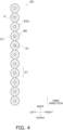
- FIG. 4 is a schematic cross-sectional view of the heat transfer tube 60 taken along the line IV-IV in FIG. 2 .
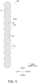
- FIG. 5 is a schematic cross-sectional view of the heat transfer tube 60 taken along the line V-V in FIG. 2 .
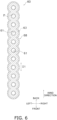
- FIG. 6 is a schematic cross-sectional view of the heat transfer tube 60 taken along the line VI-VI in FIG. 2 .
- FIG. 7 is a schematic perspective view of the heat transfer tube 60 of the heat-source heat exchanger 50.
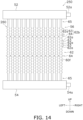
- FIG. 8 is an enlarged schematic front view of part of the heat-source heat exchanger 50.
- FIG. 8 is a diagram illustrating the contact state between the heat transfer tubes 60 and the arrangement of a first portion 62a and a second portion 62b in a first region 62 of the heat transfer tube 60
- FIGS. 2 to 8 are schematic views illustrating the characteristics of the heat-source heat exchanger 50. Therefore, FIGS. 2 to 8 do not limit the shape, size, quantity, and the like, of the whole and part of the heat-source heat exchanger 50.
- the expressions such as up, down, left, right, front (front side), and back (back side) may be used to describe directions, positions, and the like. Unless otherwise specified, the directions and positions indicated by these expressions follow the arrows in the drawings. Furthermore, the up-down direction, the right-left direction, and the front-back direction according to the present embodiment correspond to a first direction, a second direction, and a third direction in the claims, respectively.
- the heat-source heat exchanger 50 primarily includes the gas header 52, the liquid header 54, and a heat exchange unit 56.
- the heat exchange unit 56 includes the plurality of heat transfer tubes 60. One end of each of the heat transfer tubes 60 is coupled to the gas header 52. According to the present embodiment, an upper end of each of the heat transfer tubes 60 is coupled to the gas header 52. Further, one end of each of the heat transfer tubes 60 is coupled to the liquid header 54. According to the present embodiment, a lower end of each of the heat transfer tubes 60 is coupled to the liquid header 54.
- the heat-source heat exchanger 50 is a finless heat exchanger that does not use heat transfer fins.
- heat is exchanged between the refrigerant and an external fluid (air according to the present embodiment) supplied by the heat source fan 18.
- the heat-source heat exchanger 50 is made of, for example, aluminum or an aluminum alloy. Furthermore, the material of the heat-source heat exchanger 50 is not limited to aluminum or an aluminum alloy, and may be, for example, a magnesium alloy. Materials other than those described as examples may be selected as the material of the heat-source heat exchanger 50.
- the materials of the gas header 52, the liquid header 54, and the heat transfer tubes 60 of the heat exchange unit 56 may be different from each other. However, from the viewpoint of electrolytic corrosion prevention, the materials of the gas header 52, the liquid header 54, and the heat transfer tubes 60 of the heat exchange unit 56 are preferably identical.
- the gas header 52 is a hollow member in which an internal space is formed.
- the gas header 52 linearly extends with a predetermined direction as its longitudinal direction. According to the present embodiment, for convenience of explanation, the longitudinal direction of the gas header 52 is defined as a right-left direction.
- the gas header 52 is a member having functions to split the refrigerant flowing in from the first gas refrigerant pipe 22c into the heat transfer tubes 60, and to merge the refrigerants flowing in from the heat transfer tubes 60 and flow the refrigerant into the first gas refrigerant pipe 22c. Specific descriptions will be given.
- the gas header 52 has an internal space formed therein, in which the refrigerant flows from the first gas refrigerant pipe 22c and the heat transfer tubes 60.
- each of the heat transfer tubes 60 of the heat exchange unit 56 is coupled to the gas header 52.
- the upper end of each of the heat transfer tubes 60 of the heat exchange unit 56 is coupled to the gas header 52.
- the heat transfer tubes 60 are coupled to the gas header 52 such that the heat transfer tubes 60 are arranged along the longitudinal direction of the gas header 52.
- the heat transfer tubes 60 are secured to the gas header 52 by, for example, brazing.
- the heat transfer tubes 60 are coupled to the gas header 52, and thus refrigerant channels P, described below, of the heat transfer tubes 60 communicate with the internal space of the gas header 52.
- the gas header 52 includes a coupling portion 52a that is coupled to the first gas refrigerant pipe 22c.
- the internal space of the gas header 52 communicates with the first gas refrigerant pipe 22c via the coupling portion 52a.
- the gas header 52 splits the refrigerant, flowing into the internal space from the first gas refrigerant pipe 22c, into the refrigerant channels P defined in the heat transfer tubes 60. Furthermore, when the heat-source heat exchanger 50 functions as an evaporator, the gas header 52 merges the refrigerants flowing into the internal space from the heat transfer tubes 60 and flows the refrigerant into the first gas refrigerant pipe 22c.
- the liquid header 54 is a hollow member in which an internal space is formed.
- the liquid header 54 linearly extends with a predetermined direction as its longitudinal direction.
- the liquid header 54 linearly extends with the right-left direction as its longitudinal direction.
- the liquid header 54 is provided at a position immediately under the gas header 52 and corresponding to the gas header 52.
- the heat-source heat exchanger 50 is installed in a casing, not illustrated, of the heat source unit 10 in such a posture that the heat transfer tubes 60 coupled to the gas header 52 and the liquid header 54 extend in a vertical direction.
- the liquid header 54 is a member having functions to split the refrigerant flowing in from the liquid refrigerant pipe 22d into the heat transfer tubes 60 and merge the refrigerants flowing in from the heat transfer tubes 60 and flow the refrigerant into the liquid refrigerant pipe 22d. Specific descriptions will be given.
- the liquid header 54 has an internal space formed therein, in which the liquid refrigerant flows from the liquid refrigerant pipe 22d and the heat transfer tubes 60.
- each of the heat transfer tubes 60 of the heat exchange unit 56 is coupled to the liquid header 54.
- the lower end of each of the heat transfer tubes 60 of the heat exchange unit 56 is coupled to the liquid header 54.
- the heat transfer tubes 60 are coupled to the liquid header 54 such that the heat transfer tubes 60 are arranged along the longitudinal direction of the liquid header 54.
- Each of the heat transfer tubes 60 having one end coupled to the liquid header 54 and the other end coupled to the gas header 52 extends in the vertical direction.
- the heat transfer tubes 60 are secured to the liquid header 54 by, for example, brazing.
- the heat transfer tubes 60 are coupled to the liquid header 54, and thus the refrigerant channels P, described below, of the heat transfer tubes 60 communicate with the internal space of the liquid header 54.
- the liquid header 54 includes a coupling portion 54a that is coupled to the liquid refrigerant pipe 22d.
- the internal space of the liquid header 54 communicates with the liquid refrigerant pipe 22d via the coupling portion 54a.
- the liquid header 54 merges the liquid refrigerants flowing into the internal space from the heat transfer tubes 60 and flows the liquid refrigerant into the liquid refrigerant pipe 22d. Further, when the heat-source heat exchanger 50 functions as an evaporator, the liquid header 54 splits the liquid refrigerant or the gas-liquid two phase refrigerant, flowing into the internal space from the liquid refrigerant pipe 22d, into the refrigerant channels P defined in the heat transfer tubes 60.
- the heat exchange unit 56 includes the heat transfer tubes 60.
- each of the heat transfer tubes 60 extends in the up-down direction (the first direction) as its longitudinal direction.
- the channel (the refrigerant channel P) of the refrigerant extending in the longitudinal direction is defined.
- each of the heat transfer tubes 60 is a flat multi-hole tube in which the refrigerant channels P are formed.
- the refrigerant channels P extending along the vertical direction are formed in each of the heat transfer tubes 60 (see FIG. 7 ).
- the number of refrigerant channels P formed in each of the heat transfer tubes 60 is not limited to the number of refrigerant channels P illustrated in the drawing.
- each of the heat transfer tubes 60 When each of the heat transfer tubes 60 is cut along the plane orthogonal to the longitudinal direction of the heat transfer tubes 60 and a certain direction is defined as a longitudinal direction (hereafter, this direction is referred to as a cross-sectional longitudinal direction D1), each of the heat transfer tubes 60 has a flat cross-section with a small width in a direction orthogonal to the cross-sectional longitudinal direction D1. Further, in the following description, unless otherwise specified, the expression "the cross-section of the heat transfer tube 60" refers to the cross-section when the heat transfer tube 60 is cut along the plane orthogonal to the longitudinal direction (the up-down direction in the state where the heat-source heat exchanger 50 is installed).
- the cross-section of each of the heat transfer tubes 60 has a shape in which a plurality of circular tubes is arranged in the cross-sectional longitudinal direction D1, as illustrated in FIG. 3 , for example.
- the cross-section illustrated in FIG. 3 is merely a schematic illustration of the cross-section of the heat transfer tube 60 and is not a specific limitation on the cross-sectional shape of the heat transfer tube 60.
- the cross-sectional shape of the heat transfer tube 60 is not limited to the shape illustrated in FIG. 3 , and its outer shape may be a flat square shape.
- the cross-section of each of the heat transfer tubes 60 preferably has a concave and convex shape along the cross-sectional longitudinal direction D1, as illustrated in FIG. 3 , for example.
- each of the heat transfer tubes 60 a plurality of holes 61 defining the refrigerant channels P are arranged side by side along the cross-sectional longitudinal direction D1 as illustrated in FIG. 3 , for example.
- the shape of the hole 61 is circular, but the shape of the hole 61 may be other than a circular shape (e.g., a square shape).
- the heat transfer tube 60 is attached to the gas header 52 and the liquid header 54 in such a posture that the direction in which the cross-sectional longitudinal direction D1 of the heat transfer tube 60 extends matches the front-back direction.
- the front-back direction along the cross-sectional longitudinal direction D1 of the heat transfer tube 60 substantially matches the flow direction of the air generated by the heat source fan 18.
- the heat source fan 18 is disposed in front of the heat-source heat exchanger 50 to blow air backward toward the heat-source heat exchanger 50.
- the air delivered by the heat source fan 18 may be efficiently brought into contact with the side surface of the heat transfer tube 60 extending along the cross-sectional longitudinal direction D1 while air flow resistance of the heat-source heat exchanger 50 is suppressed, and thus a high heat exchange efficiency may be achieved.
- the heat transfer tubes 60 are arranged side by side in a direction intersecting with the cross-sectional longitudinal direction D1. Specifically, the heat transfer tubes 60 are attached to the gas header 52 and the liquid header 54 so as to be arranged in a direction orthogonal to the cross-sectional longitudinal direction D1. In other words, according to the present embodiment, the heat transfer tubes 60 are arranged side by side in the right-left direction.
- the refrigerant channels P extending in the first direction, are arranged along the second direction intersecting with the first direction and are arranged along the third direction intersecting with the first direction and the second direction.
- the refrigerant channels P, extending in the vertical direction are arranged along the right-left direction orthogonal to the vertical direction and are arranged along the front-back direction orthogonal to the vertical direction and the right-left direction.
- the heat transfer tube 60 of the heat-source heat exchanger 50 includes portions in which at least one of the size of the outer edge or the size of the inner edge is different in the up-down direction in which the refrigerant channel P extends.
- at least one of the size of the outer edge or the size of the inner edge is different between a first position and a second position (different from the first position) in the up-down direction in which the refrigerant channel P extends.
- the size of the outer edge of the heat transfer tube 60 at a certain position in the up-down direction in which the refrigerant channel P extends refers to the length of the outer edge of the cross-section when the heat transfer tube 60 is cut at that position along the plane orthogonal to the up-down direction.
- the size of the inner edge of the heat transfer tube 60 at a certain position in the up-down direction in which the refrigerant channel P extends refers to the total length of the outer periphery of the hole 61 when the heat transfer tube 60 is cut at that position along the plane orthogonal to the up-down direction.
- Each of the heat transfer tubes 60 includes the first region 62, a second region 66, and a third region 68 having different size characteristics of the outer edge and/or the inner edge in the up-down direction.
- the positions of the first region 62, the second region 66, and the third region 68, the shapes of the heat transfer tube 60 in the first region 62, the second region 66, and the third region 68, and the like, will be described below.
- the second region 66 is a lower region of the heat transfer tube 60.
- the second region 66 is a region of an end portion of the heat transfer tube 60 on the side coupled to the liquid header 54.
- the heat transfer tube 60 is coupled to the liquid header 54 in the portion of the second region 66 of the heat transfer tube 60.
- the second region 66 of the heat transfer tube 60 is an example of a liquid header coupling portion in the claims.
- the range where the second region 66 is present is not limited, for example, the second region 66 is provided in a range above the lower end of the heat transfer tube 60 by a length corresponding to 10% of the length of the heat transfer tube 60 in the up-down direction.
- the third region 68 is an upper region of the heat transfer tube 60.
- the third region 68 is a region of an end portion of the heat transfer tube 60 on the side coupled to the gas header 52.
- the heat transfer tube 60 is coupled to the gas header 52 in the portion of the third region 68 of the heat transfer tube 60.
- the third region 68 of the heat transfer tube 60 is an example of a gas header coupling portion in the claims.
- the range where the third region 68 is present is not limited, for example, the third region 68 is provided in a range under the upper end of the heat transfer tube 60 by a length corresponding to 10% of the length of the heat transfer tube 60 in the up-down direction.
- the first region 62 is provided between the second region 66 and the third region 68 in the up-down direction.
- the first region 62 is provided at least in a central portion of the heat transfer tube 60 in the up-down direction.
- the central portion of the heat transfer tube 60 refers to a range having a length corresponding to 25% of the length of the heat transfer tube 60 in the up-down direction downward and upward from the center of the heat transfer tube 60 in the up-down direction.
- the first region 62 and the second region 66 may be arranged adjacent to each other in the up-down direction. Furthermore, a region that does not belong to either the first region 62 or the second region 66 described below may be present between the first region 62 and the second region 66. Further, similarly, the first region 62 and the third region 68 may be arranged adjacent to each other in the up-down direction, or a region that does not belong to either the first region 62 or the third region 68 described below may be present between the first region 62 and the third region 68.
- the shapes of the heat transfer tube 60 in the first region 62, the second region 66, and the third region 68 will be described.
- the heat transfer tube 60 in the first region 62 is provided with the first portion 62a and the second portion 62b.
- the second portion 62b includes a non-contact portion 63 and a contact portion 64.
- the contact portion 64 is an example of a protrusion and a second protrusion in the claims.
- the non-contact portion 63 and the contact portion 64 in the second portion 62b protrude in a direction intersecting with the up-down direction with respect to the first portion 62a.
- the non-contact portion 63 and the contact portion 64 protrude at least in the right-left direction, i.e., toward the adjacent heat transfer tube 60, with respect to the first portion 62a.
- the non-contact portion 63 and the contact portion 64 have different protruding amounts with respect to the first portion 62a. Specifically, the protruding amount of the contact portion 64 with respect to the first portion 62a is larger than the protruding amount of the non-contact portion 63 with respect to the first portion 62a. Further, the non-contact portion 63 is not in contact with the outer surface 60f of the adjacent heat transfer tube 60, while the contact portion 64 is in contact with the outer surface 60f of the heat transfer tube 60 adjacent thereto in the right-left direction.
- the non-contact portion 63 and the contact portion 64 are different from each other in that the contact portion 64 is provided with a concave portion 64a and the non-contact portion 63 is not provided with the concave portion 64a.
- the concave portion 64a includes a groove portion that is concave in a direction away from the heat transfer tube 60 in contact with the contact portion 64 and that extends along the front-back direction.
- the first portion 62a and the second portion 62b protruding in a direction intersecting with the up-down direction with respect to the first portion 62a are alternately formed along the up-down direction in the heat transfer tube 60 (see FIG. 2 ).
- the first portion 62a (concave portion) and the second portion 62b (convex portion) are alternately provided along the up-down direction in the first region 62 of the heat transfer tube 60 so that the outer surface 60f of the first region 62 of the heat transfer tube 60 has concave and convex along the up-down direction (see FIG. 2 ).
- the size of the outer edge of the non-contact portion 63 is thus larger than the size of the outer edge of the first portion 62a, as illustrated in FIG. 5 .
- the cross-section of the first portion 62a is indicated in a dashed-two dotted line, and the size of the outer edge of the non-contact portion 63 is indicated in a solid line.
- the size of the outer edge of the contact portion 64 is also larger than the size of the outer edge of the first portion 62a. Further, the size of the outer edge of the contact portion 64 is larger than the size of the outer edge of the non-contact portion 63.
- the size of the inner edge of the non-contact portion 63 is also larger than the size of the inner edge of the first portion 62a.
- the size of the inner edge of the contact portion 64 is also larger than the size of the inner edge of the first portion 62a.
- the size of the hole 61 in the non-contact portion 63 and the contact portion 64 is larger than the size of the hole 61 in the first portion 62a.
- the channel area of the refrigerant channel P in the non-contact portion 63 and the contact portion 64 is larger than the channel area of the refrigerant channel P in the first portion 62a.
- all the heat transfer tubes 60 include the first region 62. Further, the first region 62 is provided at the same position in the up-down direction in all the heat transfer tubes 60. Further, in the first region 62 of each of the heat transfer tubes 60, the first portion 62a, the non-contact portion 63, and the contact portion 64 are provided at the same positions in the up-down direction. In short, in the heat-source heat exchanger 50 according to the present embodiment, the first portions 62a, the non-contact portions 63, and the contact portions 64 are arranged at the same positions in the up-down direction and arranged side by side in the right-left direction.
- both of a certain heat transfer tube 60 (referred to as the first heat transfer tube 60) and the heat transfer tube 60 (referred to as the second heat transfer tube 60) adjacent to the first heat transfer tube 60 in the right-left direction include the first region 62.
- the non-contact portion 63 of the first heat transfer tube 60 and the non-contact portion 63 of the second heat transfer tube 60 are formed at the identical position in the up-down direction.
- the contact portion 64 of the first heat transfer tube 60 and the contact portion 64 of the second heat transfer tube 60 are formed at the identical position in the up-down direction.
- the contact portion 64 of the first heat transfer tube 60 is in contact with the contact portion 64 of the second heat transfer tube 60 adjacent thereto in the right-left direction.
- the first region 62 of the heat transfer tube 60 is formed at least in the central portion of the heat transfer tube 60 in the longitudinal direction (the up-down direction according to the present embodiment) of the heat transfer tube 60 in which the refrigerant channel P extends.
- the first region 62 of the heat transfer tube 60 is formed in a central region of the heat transfer tube 60 (the central portion of the heat transfer tube 60 and the periphery thereof) in the longitudinal direction of the heat transfer tube 60.
- the central region of the heat transfer tube 60 is a region where heat is actively exchanged between the refrigerant and the external fluid both when the heat-source heat exchanger 50 functions as a condenser and when the heat-source heat exchanger 50 functions as an evaporator.
- the gas-liquid two phase refrigerant primarily flows in the central region of the heat transfer tube 60 both when the heat-source heat exchanger 50 functions as a condenser and when the heat-source heat exchanger 50 functions as an evaporator.
- the outer surface 60f of the heat transfer tube 60 has concave and convex foamed repeatedly thereon along the up-down direction.
- the heat transfer tube 60 repeatedly expands and contracts along the up-down direction.
- the size of the outer edge of the heat transfer tube 60 repeatedly expands and contracts along the up-down direction.
- the size of the inner edge of the heat transfer tube 60 also repeatedly expands and contracts along the up-down direction.
- the area of the refrigerant channel P of the heat transfer tube 60 also repeatedly expands and contracts along the up-down direction.
- the first region 62 in which the outer edge of the heat transfer tube 60 repeatedly expands and contracts along the up-down direction (the direction in which the refrigerant channel P extends), is provided in the central region of the heat transfer tube 60, i.e., the region where the gas-liquid two phase refrigerant primarily flows, the heat transfer efficiency between the refrigerant and the external fluid may be improved.
- the first region 62 in which the size of the inner edge of the heat transfer tube 60 repeatedly expands and contracts along the up-down direction (the direction in which the refrigerant channel P extends), is provided in the central region of the heat transfer tube 60, i.e., in the region where the gas-liquid two phase refrigerant primarily flows, the pressure loss of the refrigerant flowing through the refrigerant channel P may be suppressed.
- frost formation may occur on the heat-source heat exchanger in some operating conditions. Such frost formation is likely to occur in the heat-source heat exchanger, in particular, on the upstream side in the flow direction of the external fluid (air) that exchanges heat with the refrigerant.
- frost formation is likely to occur on the front-side end portion of the heat transfer tube 60 of the heat-source heat exchanger 50.
- first region 62 is not provided in the heat transfer tube 60 and the portions expanding and contracting along the longitudinal direction (the up-down direction) of the heat transfer tube 60 are not provided in the windward-side end portion of the heat transfer tube 60, i.e., if the width of the windward-side end portion of the heat transfer tube 60 in the right-left direction is uniform along the longitudinal direction of the heat transfer tube 60, frost formation occurs substantially uniformly in the windward-side end portion of the heat transfer tube 60.
- a failure in which the frost adhering to the windward-side end portion of the heat transfer tube 60 block the channel of the air, and the air is not delivered to the leeward side beyond the windward-side end portion of the heat transfer tube 60, may occur at a relatively early timing after the start of operation of the air conditioning apparatus 100.
- the heat transfer tube 60 has the first region 62, and the first portion 62a having a relatively small outer edge and the second portion 62b having a relatively large outer edge are provided in the heat transfer tube 60 along the up-down direction.
- frost formation on the windward-side end portion of the heat transfer tube 60 is likely to concentrate on the convex portion (i.e., the second portion 62b).
- the heat transfer tube 60 may suppress frost formation on the first portion 62a of the first region 62 in the windward-side end portion of the heat transfer tube 60 and may at least delay the occurrence of a failure in which frost formation on the windward-side end portion of the heat transfer tube 60 blocks the channel of the air. Therefore, in the air conditioning apparatus 100 using the heat-source heat exchanger 50, the heating operation may continue for a relatively long time without being stopped for defrosting of the heat-source heat exchanger 50.
- the non-contact portions 63 and the contact portions 64 of the first regions 62 of the adjacent heat transfer tubes 60 are formed at the identical position in the up-down direction.
- the first portions 62a of the first regions 62 of the adjacent heat transfer tubes 60 are formed at the identical position in the up-down direction. Therefore, in the heat-source heat exchanger 50 according to the present embodiment, a relatively large air channel may be ensured between the first portions 62a of the first regions 62 of the adjacent heat transfer tubes 60. Therefore, blockage of the air channel due to frost adhering to the windward-side end portion of the heat transfer tube 60 is easily suppressed in particular.
- the second portions 62b of the first region 62 of the heat transfer tube 60 are preferably provided over substantially the entire region of the heat transfer tube 60 in the vertical direction.
- the contact portion 64 of the heat transfer tube 60 is in contact with the contact portion 64 of the heat transfer tube 60 adjacent thereto in the right-left direction.
- the distance between the heat transfer tubes 60 may be adjusted to a predetermined distance.
- the contact portions 64 of the heat transfer tubes 60 adjacent to each other in the right-left direction are in contact with each other in the heat-source heat exchanger 50, it is possible to suppress the occurrence of the state where the heat transfer tubes 60 adjacent to each other in the right-left direction excessively approach each other or excessively separate from each other.
- the contact portion 64 of the heat transfer tube 60 functions as a spacer that adjusts the arrangement pitch of the heat transfer tubes 60.
- Adjustment of the arrangement pitch between the heat transfer tubes 60 may be achieved by a spacer separate from the heat transfer tube 60 provided between the heat transfer tubes 60.
- the use of the contact portion 64 formed in the heat transfer tube 60 itself as a spacer may reduce the cost of providing a spacer separate from the heat transfer tube 60, the labor cost for attaching the spacer separate from the heat transfer tube 60 to the heat transfer tube 60, etc.
- the second region 66 of the heat transfer tube 60 is an example of the liquid header coupling portion in the claims.
- the second region 66 of the heat transfer tube 60 is inserted into the liquid header 54, and at least part of the second region 66 of the heat transfer tube 60 is coupled to the liquid header 54.
- the second region 66 of the heat transfer tube 60 does not include concave and convex (enlarged portion and contracted portion) on the outer surface 60f.
- the size of the outer edge of the heat transfer tube 60 is uniform.
- the size of the inner edge of the heat transfer tube 60 is uniform.
- the second region 66 of the heat transfer tube 60 is a portion where the size of the inner edge of the heat transfer tube 60 is formed to be smaller than those of the portions other than the second region 66 of the heat transfer tube 60. Specifically, the size of the inner edge of the heat transfer tube 60 in the second region 66 is smaller than the average size of the inner edges of the heat transfer tube 60 other than the second region 66. Further, as illustrated in FIG. 4 , the size of the inner edge of the heat transfer tube 60 in the second region 66 is smaller than the size of the inner edge of the heat transfer tube 60 in the first portion 62a of the first region 62. In FIG. 4 , the cross-section of the second region 66 is indicated in a solid line, and the cross-section of the first portion 62a in the first region 62 of the heat transfer tube 60 is indicated in a dashed-two dotted line.
- the second region 66 of the heat transfer tube 60 is a portion where the size of the outer edge of the heat transfer tube 60 is formed to be smaller than those of the portions of the heat transfer tube 60 other than the second region 66. Specifically, the size of the outer edge of the heat transfer tube 60 in the second region 66 is smaller than the average size of the outer edges of the heat transfer tube 60 other than the second region 66. Further, as illustrated in FIG. 4 , the size of the outer edge of the heat transfer tube 60 in the second region 66 is smaller than the size of the outer edge of the heat transfer tube 60 in the first portion 62a of the first region 62.
- the second region 66 of the heat transfer tube 60 is formed in the end portion of the heat transfer tube 60 on the side coupled to the liquid header 54. Therefore, the liquid refrigerant primarily flows at the position corresponding to the second region 66 in the refrigerant channel P of the heat transfer tube 60 both when the heat-source heat exchanger 50 functions as a condenser and when the heat-source heat exchanger 50 functions as an evaporator.
- the second region 66 in which the size of the inner edge of the heat transfer tube 60 is smaller than the sizes of the inner edges of the other portions of the heat transfer tube 60, is provided in the place where the liquid refrigerant primarily flows, which has a smaller volume than the gas refrigerant (in the case of the same mass and the same pressure).
- the heat transfer coefficient between the external fluid and the refrigerant (primarily liquid refrigerant) in the second region 66 via the heat transfer tube 60 may be improved.
- the third region 68 of the heat transfer tube 60 is an example of the gas header coupling portion in the claims.
- the third region 68 of the heat transfer tube 60 is inserted into the gas header 52, and at least part of the third region 68 of the heat transfer tube 60 is coupled to the gas header 52.
- the third region 68 of the heat transfer tube 60 is an example of the protrusion in the claims.
- the outer surface 60f of the third region 68 of the heat transfer tube 60 protrudes in the direction intersecting with the up-down direction, which is the longitudinal direction of the heat transfer tube 60, with respect to a portion adjacent to the third region 68 of the heat transfer tube 60 (a portion below the third region 68 of the heat transfer tube 60) and is in contact with the outer surface 60f of the adjacent heat transfer tube 60.
- the third region 68 of the heat transfer tube 60 is an example of a first protrusion in the claims, which is provided in an end portion of the heat transfer tube 60 in the up-down direction that is the longitudinal direction of the heat transfer tube 60.
- the third region 68 of the heat transfer tube 60 does not include concave and convex (enlarged portion and contracted portion) on the outer surface 60f.
- the size of the inner edge of the heat transfer tube 60 is uniform.
- the size of the outer edge of the heat transfer tube 60 is uniform.
- the third region 68 of the heat transfer tube 60 is a portion where the size of the inner edge of the heat transfer tube 60 is formed to be larger than those of the portions other than the third region 68 of the heat transfer tube 60. Specifically, the size of the inner edge of the heat transfer tube 60 in the third region 68 is larger than the average size of the inner edges of the heat transfer tube 60 other than the third region 68. Further, as illustrated in FIG. 6 , the size of the inner edge of the heat transfer tube 60 in the third region 68 is larger than the size of the inner edge of the heat transfer tube 60 in the non-contact portion 63 of the first region 62. Further, in FIG. 6 , the cross-section of the third region 68 is indicated in a solid line, and the cross-section of the non-contact portion 63 of the first region 62 of the heat transfer tube 60 is indicated in a dashed-two dotted line.
- the third region 68 of the heat transfer tube 60 is a portion in which the size of the outer edge of the heat transfer tube 60 is formed to be larger than those of the portions of the heat transfer tube 60 other than the third region 68. Specifically, the size of the outer edge of the heat transfer tube 60 in the third region 68 is larger than the average size of the outer edges of the heat transfer tube 60 other than the third region 68. Further, as illustrated in FIG. 6 , the size of the outer edge of the heat transfer tube 60 in the third region 68 is larger than the size of the outer edge of the heat transfer tube 60 in the non-contact portion 63 of the first region 62.
- the size of the outer edge of the heat transfer tube 60 in the third region 68 is the same as the size of the outer edge of the heat transfer tube 60 in the contact portion 64 of the first region 62.
- the maximum width of the heat transfer tube 60 in the third region 68 in the right-left direction is the same as the maximum width of the contact portion 64 of the first region 62 in the right-left direction.
- the third region 68 of the heat transfer tube 60 is in contact with the third region 68 of the heat transfer tube 60 adjacent thereto in the right-left direction.
- the third region 68 of the heat transfer tube 60 is preferably provided with a concave portion similar to the concave portion 64a of the contact portion 64.
- a length B 1 of the third region 68 of the heat transfer tube 60 is preferably longer than a length B2 of the contact portion 64 of the first region 62 of the heat transfer tube 60 (see FIG. 2 ).
- the length B1, in the up-down direction, of the third region 68 of the heat transfer tube 60 which is an example of the first protrusion provided in the end portion of the heat transfer tube 60 in the up-down direction (the first direction)
- the length B2 in the up-down direction, of the contact portion 64 of the heat transfer tube 60 which is an example of the second protrusion provided in a portion of the heat transfer tube 60 other than the end portion in the up-down direction.
- the third region 68 of the heat transfer tube 60 is formed in the end portion of the heat transfer tube 60 on the side coupled to the gas header 52. Therefore, the gas refrigerant primarily flows at the position corresponding to the third region 68 in the refrigerant channel P of the heat transfer tube 60 both when the heat-source heat exchanger 50 functions as a condenser and when the heat-source heat exchanger 50 functions as an evaporator.
- the third region 68 of the heat transfer tube 60 in which the size of the inner edge of the heat transfer tube 60 is larger than the sizes of the inner edges of the other portions of the heat transfer tube 60, is provided in the place where the gas refrigerant primarily flows, which has a larger volume than the liquid refrigerant (in the case of the same mass and the same pressure).
- the pressure loss when the refrigerant flows in the third region 68 is easily suppressed.
- the third region 68 of the heat transfer tube 60 is in contact with the third region 68 of the heat transfer tube 60 adjacent thereto in the right-left direction.
- the distance between the heat transfer tubes 60 may be adjusted to a predetermined distance.
- the third regions 68 of the heat transfer tubes 60 adjacent to each other in the right-left direction are in contact with each other in the heat-source heat exchanger 50, it is possible to suppress the occurrence of the state where the heat transfer tubes 60 adjacent to each other in the right-left direction excessively approach each other or excessively separate from each other.
- the third region 68 of the heat transfer tube 60 functions as a spacer that adjusts the arrangement pitch of the heat transfer tubes 60, similarly to the contact portion 64.
- the length B 1 of the third region 68 of the heat transfer tube 60 is longer than the length B2 of the contact portion 64 of the heat transfer tube 60.
- the length B 1 of the third region 68 in the end portion of the heat transfer tube 60 in the longitudinal direction of the heat transfer tube 60 is relatively long in this way, it is easy to ensure a brazing margin between the third region 68 of the heat transfer tube 60 and the gas header 52.
- a flat multi-hole tube including none of the first region 62, the second region 66, and the third region 68 is prepared as a material of the heat transfer tube 60.
- a flat multi-hole tube in which the sizes of the outer edge and the inner edge of the heat transfer tube 60 are uniform along the longitudinal direction of the heat transfer tube 60 is provided as a material of the heat transfer tube 60.
- a flat multi-hole tube having the cross-section identical to that of the first portion 62a of the first region 62, but not limited thereto, is prepared as the material of the heat transfer tube 60.
- the size of the cross-section of the flat multi-hole tube to be prepared may be designed as appropriate.
- Dieless drawing processing is performed on the above flat multi-hole tube (material) to form the heat transfer tube 60 including the first region 62, the second region 66, and the third region 68.
- dieless drawing processing is performed on a flat multi-hole tube having the cross-section identical to that of the first portion 62a of the first region 62 to thus form the second portion 62b (the non-contact portion 63 and the contact portion 64 (including the concave portion 64a)) of the first region 62, the second region 66, the third region 68, and the like.
- the dieless drawing processing is a processing method in which a material (here, a flat multi-hole tube before processing) is locally heated by a heating unit using a high-frequency induction heating device, a laser heating device, or the like, and the heating unit (i.e., an area heated by the heating unit) is moved relative to the material in the longitudinal direction of the material (the longitudinal direction of the flat multi-hole tube) while a force along the longitudinal direction of the material is applied to a portion of the material heated by the heating unit to cause the material to protrude in a direction intersecting with the longitudinal direction or stretch in the longitudinal direction.
- deformation to increase the size of the outer edge i.e., compression of the material in the longitudinal direction
- deformation to decrease the size of the outer edge i.e., stretching of the material in the longitudinal direction
- the size of the inner edge also decreases the size of the inner edge.
- the use of dieless drawing processing as the method for processing the heat transfer tube 60 makes it possible to manufacture the heat transfer tube 60 having the above-described shape in a relatively easy manner and in a relatively short time without undergoing a plurality of steps.
- the heat transfer tubes 60 formed by dieless drawing are arranged in a direction orthogonal to the cross-sectional longitudinal direction D1 in a state where both end portions of the heat transfer tubes 60 are aligned, and the end portions thereof are coupled to the gas header 52 and the liquid header 54 in a state where the heat transfer tubes 60 are stacked in the direction orthogonal to the cross-sectional longitudinal direction D1.
- the contact portion 64 and the third region 68 of the heat transfer tube 60 are in contact with the outer surface 60f of the heat transfer tube 60 adjacent thereto in the right-left direction (the contact portion 64 and the third region 68 of the heat transfer tube 60 adjacent thereto in the right-left direction), and therefore the distance between the heat transfer tubes 60 (the arrangement pitch of the heat transfer tubes 60) is adjusted to a predetermined distance.
- the size of the outer edge and the size of the inner edge of the flat multi-hole tube simultaneously change.
- a processing method, different from the dieless drawing processing, in which only one of the size of the outer edge or the size of the inner edge is changed may be at least partially used.
- the refrigerant channels P extending in the vertical direction are arranged along the right-left direction intersecting with the vertical direction and are arranged along the front-back direction intersecting with the vertical direction and the right-left direction.
- the vertical direction, the right-left direction, and the front-back direction are examples of the first direction, the second direction, and the third direction in the claims, respectively.
- the heat-source heat exchanger 50 includes the heat transfer tubes 60 defining the refrigerant channels P. In the heat transfer tube 60, at least one of the size of the outer edge and the size of the inner edge is different between the first position and the second position in the vertical direction.
- the heat-source heat exchanger 50 In the heat-source heat exchanger 50 according to the present embodiment, at least one of the sizes of the outer edge and the inner edge of the heat transfer tube 60 is changed along the refrigerant channel P. It is therefore possible to improve the efficiency of the heat-source heat exchanger 50 in accordance with the state change of the refrigerant in each of the refrigerant channels P.
- the size of the outer edge of the heat transfer tube 60 is changed along the longitudinal direction (vertical direction) of the heat transfer tube 60, and concave and convex are provided on the heat transfer tube 60 along the longitudinal direction.
- a failure in which frost is uniformly formed over the entire windward-side end portion of the heat transfer tube 60 in the longitudinal direction, the channel of the air supplied to the heat-source heat exchanger 50 is blocked, and the air is not supplied to the downstream side of the heat transfer tube 60, may be suppressed.
- the air supplied by the heat source fan 18 flows from front to back.
- the size of the outer edge of the heat transfer tube 60 is changed along the longitudinal direction (vertical direction) of the heat transfer tube 60, and part (the contact portion 64 or the third region 68) of the heat transfer tube 60 is in contact with the heat transfer tube 60 adjacent thereto in the right-left direction.
- the arrangement pitch of the heat transfer tubes 60 may be adjusted without using a spacer that is a separate member from the heat transfer tube 60.
- the heat transfer tubes 60 defining the refrigerant channels P are flat multi-hole tubes that define a plurality of the refrigerant channels P arranged along the front-back direction.
- the use of the flat multi-hole tubes as the heat transfer tubes 60 enables efficient heat exchange between the refrigerant and the external fluid without using heat transfer fins.
- the heat transfer tube 60 includes the first region 62 in which the first portion 62a and the second portion 62b are alternately formed along the vertical direction.
- the second portion 62b protrudes in the direction intersecting with the vertical direction with respect to the first portion 62a.
- the first portion 62a (concave portion) and the second portion 62b (convex portion) are alternately provided along the vertical direction so that the heat exchange efficiency in the first region 62 of the heat transfer tube 60 may be improved.
- the heat transfer tube 60 includes the first region 62 that repeatedly expands and contracts along the vertical direction, it is possible to intensively cause frost formation in the expanded portion (the second portion 62b) in the vertical direction of the heat transfer tube 60. Therefore, it is easy to suppress a failure, in which frost is uniformly formed over the entire windward-side end portion of the heat transfer tube 60 in the vertical direction, the channel of the air supplied to the heat-source heat exchanger 50 is blocked, and the air is not supplied to the downstream side of the heat transfer tube 60.
- a first heat transfer tube of the heat transfer tubes 60 and a second heat transfer tube of the heat transfer tubes 60, that are adjacent to each other in the right-left direction, include the first region 62.
- the second portion 62b of the first heat transfer tubes 60 and the second portion 62b of the second heat transfer tubes 60 are formed at the identical position.
- the positions of the second portions 62b of the heat transfer tubes 60 adjacent to each other in the right-left direction are identical in the vertical direction
- the positions of the first portions 62a of the heat transfer tubes 60 adjacent to each other in the right-left direction are also identical in the vertical direction. Therefore, in the heat-source heat exchanger 50, a relatively large gap may be formed between the first portions 62a (concave portions) of the adjacent heat transfer tubes 60, and a relatively large channel of the external fluid may be thus ensured.
- the first region 62 is provided at least in the central portion of the heat transfer tube 60 in the vertical direction.
- heat-source heat exchanger 50 As a concave and convex structure is disposed along the vertical direction in the central portion of the heat transfer tube 60 in the vertical direction in which heat is primarily exchanged. Therefore, a high heat exchange efficiency may be easily achieved.
- the heat-source heat exchanger 50 includes the gas header 52 to which one end of the heat transfer tube 60 is coupled.
- the heat-source heat exchanger 50 has the configurations (A) and (B) below.
- the heat-source heat exchanger 50 has the above-described configurations (A) and (B), in particular, the configuration (A), it is easy to suppress the pressure loss in the third region 68 of the heat transfer tube 60 through which the gas refrigerant primarily flows.
- the heat-source heat exchanger 50 includes the liquid header 54 to which one end of the heat transfer tube 60 is coupled.
- the heat-source heat exchanger 50 has the configurations (C) and (D) below.
- the size of the inner edge of the heat transfer tube 60 in the second region 66 as an example of the liquid header coupling portion, coupled to the liquid header in the heat transfer tube 60 is smaller than the average size of the inner edges of the heat transfer tube 60 other than the second region 66.
- the size of the outer edge of the heat transfer tube 60 in the second region 66 coupled to the liquid header in the heat transfer tube 60 is smaller than the average size of the outer edges of the heat transfer tube 60 other than the second region 66.
- heat transfer between the liquid refrigerant flowing through the third region 68 and the external fluid may be promoted.
- the size of the outer edge of the heat transfer tube 60 in the portion where the first portion 62a is formed is larger than the size of the outer edge of the heat transfer tube 60 in the second region 66 of the heat transfer tube 60 coupled to the liquid header 54.
- the size of the outer edge of the heat transfer tube 60 in the portion where the second portion 62b is formed is equal to or smaller than the size of the outer edge of the heat transfer tube 60 in the third region 68 of the heat transfer tube 60 coupled to the gas header 52.
- the size of the outer edge of the heat transfer tube 60 corresponds to the shape corresponding to a change in the state of the refrigerant in the direction in which the refrigerant channel P extends. Therefore, the heat transfer efficiency of the heat-source heat exchanger 50 may be improved and the pressure loss in the heat-source heat exchanger 50 may be reduced.
- the outer surface 60f of the heat transfer tube 60 is provided with the protrusion that protrudes in the direction intersecting with the vertical direction and is in contact with the outer surface 60f of the heat transfer tube 60 adjacent thereto in the right-left direction.
- the protrusion includes the contact portion 64 and the third region 68.
- the arrangement pitch of the heat transfer tubes 60 adjacent to each other in the right-left direction may be adjusted without providing a spacer that is a different member from the heat transfer tube 60.
- the arrangement pitch of the heat transfer tubes 60 is maintained at an appropriate distance so that it is possible to ensure an appropriate channel of the external fluid between the heat transfer tubes 60 adjacent to each other in the right-left direction, and it is possible to suppress a local decrease in the heat exchange efficiency due to the fact that the channel of the external fluid is not ensured.
- the protrusion (the contact portion 64 and the third region 68) of the heat transfer tube 60 is in contact with the protrusion of the heat transfer tube 60 adjacent thereto in the right-left direction.
- the protrusions are in contact with each other, and thus it is possible to ensure a relatively large channel of the external fluid between the heat transfer tubes 60 adjacent to each other in the right-left direction, and it is possible to suppress a local decrease in the heat exchange efficiency due to the fact that the channel of the external fluid is not ensured.
- the contact portion 64 is provided with the concave portion 64a extending along the front-back direction. Furthermore, the third region 68 of the heat transfer tube 60 is also provided with a concave portion (not illustrated) extending along the front-back direction.
- the heat-source heat exchanger 50 includes the third region 68, which is an example of the first protrusion, and the contact portion 64, which is an example of the second protrusion, as protrusions in the claims.
- the third region 68 of the heat transfer tube 60 is provided in the end portion of the heat transfer tube 60 in the vertical direction.
- the contact portion 64 is provided in a portion of the heat transfer tube 60 other than the end portion in the vertical direction.
- the length B1 of the third region 68 in the vertical direction is longer than the length B2 of the contact portion 64 in the vertical direction.
- the third regions 68 provided in the end portion of the heat transfer tube 60 in the vertical direction has the relatively long length B1, and therefore it is easy to ensure a brazing margin between the heat transfer tube 60 and the header (in particular, the gas header 52 according to the present embodiment).
- the heat transfer tube 60 is formed by dieless drawing.
- the heat transfer tube 60 in which at least one of the size of the outer edge or the size of the inner edge is different between the first position and the second position in the longitudinal direction of the heat transfer tube 60 in the heat-source heat exchanger 50 according to the present embodiment, may be manufactured in a relatively easy manner and in a relatively short time, and therefore desired manufacturability is achieved.
- FIG. 9 is an enlarged schematic front view of part of the heat-source heat exchanger 50 to illustrate the contact state between the heat transfer tubes 60 (60a1, 60a2) and the arrangement of the first portion 62a and the second portion 62b (the non-contact portion 63, the contact portion 64) in the first region 62 of the heat transfer tubes 60a1, 60a2 in the heat-source heat exchanger 50 according to the second embodiment.
- the air conditioning apparatus 100 using the heat-source heat exchanger 50 according to the second embodiment is similar to the air conditioning apparatus 100 described according to the first embodiment, and therefore the description thereof will be omitted.
- the heat-source heat exchanger 50 according to the second embodiment is substantially the same as the heat-source heat exchanger 50 according to the first embodiment except that the non-contact portions 63 are formed at different positions in the heat transfer tubes 60a1, 60a2 adjacent to each other in the right-left direction. Therefore, in order to avoid duplicated descriptions, only primary differences between the heat-source heat exchanger 50 according to the second embodiment and the heat-source heat exchanger 50 according to the first embodiment will be described here.
- heat transfer tubes 60a1, 60a2 are used as the reference numerals representing the heat transfer tubes 60 in the heat-source heat exchanger 50 according to the second embodiment.
- the heat transfer tubes 60a1, 60a2 are arranged such that the heat transfer tube 60a1 and the heat transfer tube 60a2 are alternately arranged in the right-left direction, as illustrated in FIG. 9 .
- the first regions 62 are formed at a substantially identical position in the vertical direction.
- the non-contact portions 63 are formed at different positions in the vertical direction. Specifically, in the heat transfer tube 60a2, the first portion 62a is provided at the position of the non-contact portion 63 in the vertical direction in the heat transfer tube 60a1. Further, in the heat transfer tube 60a2, the non-contact portion 63 is provided at the position of the first portion 62a in the vertical direction in the heat transfer tube 60a1. In the other respects, the heat transfer tube 60a1 and the heat transfer tube 60a2 are similar.
- both the first heat transfer tube 60a1 and the second heat transfer tube 60a2 adjacent to each other in the right-left direction include the first region 62.
- the non-contact portion 63 of the first heat transfer tube 60a1 and the first portion 62a of the second heat transfer tube 60a2 are formed at the identical position, and the first portion 62a of the first heat transfer tube 60a1 and the non-contact portion 63 of the second heat transfer tube 60a2 are formed at the identical position.
- the position of the non-contact portion 63 of the heat transfer tube 60a1, 60a2 matches the position of the first portion 62a of the heat transfer tube 60a2, 60a1 adjacent in the right-left direction so that a relatively large gap may be formed between the non-contact portion 63 of the heat transfer tube 60a1, 60a2 and the heat transfer tube 60a2, 60a1 adjacent in the right-left direction. Therefore, a relatively large channel of the external fluid may be ensured between the heat transfer tubes 60a1, 60a2 adjacent in the right-left direction.
- the heat-source heat exchanger 50 according to the second embodiment has the characteristics similar to (4-1) to (4-3) and (4-5) to (4-13) described as the characteristics of the heat-source heat exchanger 50 according to the first embodiment.
- FIG. 10 is an enlarged schematic front view of part of the heat-source heat exchanger 50 to illustrate the contact state between the heat transfer tubes 60 (60b 1, 60b2) and the arrangement of the first portion 62a and the second portion 62b (the non-contact portion 63, the contact portion 64) in the first region 62 of the heat transfer tubes 60b 1, 60b2 in the heat-source heat exchanger 50 according to the third embodiment.
- the air conditioning apparatus 100 using the heat-source heat exchanger 50 according to the third embodiment is similar to the air conditioning apparatus 100 described according to the first embodiment, and therefore the description thereof will be omitted.
- the heat-source heat exchanger 50 according to the third embodiment is substantially the same as the heat-source heat exchanger 50 according to the first embodiment except that the non-contact portion 63 and the contact portion 64 are formed at different positions in the heat transfer tubes 60b 1, 60b2 adjacent to each other in the right-left direction. Therefore, in order to avoid duplicated descriptions, only primary differences between the heat-source heat exchanger 50 according to the third embodiment and the heat-source heat exchanger 50 according to the first embodiment will be described here.
- heat transfer tubes 60b1, 60b2 are used as the reference numerals representing the heat transfer tubes of the heat-source heat exchanger 50 according to the third embodiment.
- the heat transfer tubes 60b1, 60b2 are arranged such that the heat transfer tube 60b1 and the heat transfer tube 60b2 are alternately arranged in the right-left direction, as illustrated in FIG. 10 .
- the first region 62 is formed at a substantially identical position in the vertical direction.
- the non-contact portion 63 and the contact portion 64 are formed at different positions in the vertical direction.
- the first portions 62a are provided at the positions of the non-contact portion 63 and the contact portion 64 in the vertical direction in the heat transfer tube 60b1.
- the non-contact portion 63 or the contact portion 64 is provided at the position of the first portion 62a in the vertical direction in the heat transfer tube 60b1.
- the heat transfer tube 60b1 and the heat transfer tube 60b2 are similar.
- both the first heat transfer tube 60b1 and the second heat transfer tube 60b2 adjacent to each other in the right-left direction include the first region 62.
- the non-contact portion 63 and the contact portion 64 of the first heat transfer tube 60b1 and the first portion 62a of the second heat transfer tube 60b2 are formed at the identical position, and the first portion 62a of the first heat transfer tube 60b1 and the non-contact portion 63 and the contact portion 64 of the second heat transfer tube 60b2 are formed at the identical position.
- the position of the non-contact portion 63 of the heat transfer tube 60b 1, 60b2 matches the position of the first portion 62a of the heat transfer tube 60b2, 60b1 adjacent in the right-left direction so that a relatively large gap may be formed between the non-contact portion 63 of the heat transfer tube 60b1, 60b2 and the heat transfer tube 60b2, 60b1 adjacent thereto in the right-left direction. Therefore, a relatively large channel of the external fluid may be ensured between the heat transfer tubes 60b 1, 60b2 adjacent to each other in the right-left direction.
- the contact portion 64 which is an example of the protrusions of the heat transfer tube 60b1, 60b2, is in contact with a portion of the heat transfer tube 60b2, 60b1 adjacent in the right-left direction other than the contact portion 64.
- the contact portion 64 of the heat transfer tube 60b 1, 60b2 is in contact with the first portion 62a of the heat transfer tube 60b2, 60b1 adjacent in the right-left direction.
- the contact portion 64 of the heat transfer tube 60b 1, 60b2 is in contact with a portion of the heat transfer tube 60b2, 60b1 other than the contact portion 64, and therefore the compact heat-source heat exchanger 50 may be easily achieved as compared with the case where the protrusions of the heat transfer tubes are in contact with each other.
- the heat-source heat exchanger 50 according to the third embodiment has the characteristics similar to (4-1) to (4-3), (4-5) to (4-9), and (4-11) to (4-13) described as the characteristics of the heat-source heat exchanger 50 according to the first embodiment.
- FIG. 11 is an enlarged schematic front view of part of the heat-source heat exchanger 50 to illustrate the contact state between the heat transfer tubes 60 (60c1, 60c2) and the arrangement of the first portion 62a and the second portion 62b (the non-contact portion 63, the contact portion 64) in the first region 62 of the heat transfer tubes 60c1, 60c2 in the heat-source heat exchanger 50 according to the fourth embodiment.
- the air conditioning apparatus 100 using the heat-source heat exchanger 50 according to the fourth embodiment is similar to the air conditioning apparatus 100 described according to the first embodiment, and therefore the description thereof will be omitted. Further, the heat-source heat exchanger 50 according to the fourth embodiment is substantially the same as the heat-source heat exchanger 50 according to the first embodiment except that the contact portions 64 are formed at different positions in the heat transfer tubes 60c1, 60c2 adjacent to each other in the right-left direction. Therefore, in order to avoid duplicated descriptions, only primary differences between the heat-source heat exchanger 50 according to the fourth embodiment and the heat-source heat exchanger 50 according to the first embodiment will be described here.
- 60c1 and 60c2 are used as the reference numerals representing the heat transfer tubes of the heat-source heat exchanger 50 according to the fourth embodiment.
- the heat transfer tubes 60c1, 60c2 are arranged such that the heat transfer tube 60c1 and the heat transfer tube 60c2 are alternately provided in the right-left direction, as illustrated in FIG. 11 .
- the first regions 62 are formed at a substantially identical position in the vertical direction.
- the contact portions 64 are formed at different positions in the vertical direction. Specifically, in the heat transfer tube 60c2, the first portion 62a is provided at the position of the contact portion 64 in the vertical direction in the heat transfer tube 60c1. Further, in the heat transfer tube 60c2, the contact portion 64 is provided at the position of the first portion 62a in the vertical direction in the heat transfer tube 60c1. In the other respects, the heat transfer tube 60c1 and the heat transfer tube 60c2 are similar.
- the contact portion 64 which is an example of the protrusion of the heat transfer tube 60c1, 60c2, is in contact with a portion of the heat transfer tube 60c2, 60c1 adjacent in the right-left direction other than the contact portion 64.
- the contact portion 64 of the heat transfer tube 60c1, 60c2 is in contact with the first portion 62a of the heat transfer tube 60c2, 60c1 adjacent in the right-left direction.
- the contact portion 64 of the heat transfer tube 60c1, 60c2 is in contact with a portion of the heat transfer tube 60c2, 60c1 other than the contact portion 64 so that the compact heat-source heat exchanger 50 may be achieved as compared with the case where the protrusions of the heat transfer tubes are in contact with each other.
- the heat-source heat exchanger 50 according to the fourth embodiment has the characteristics similar to (4-1) to (4-9) and (4-11) to (4-13) described as the characteristics of the heat-source heat exchanger 50 according to the first embodiment.
- FIG. 12 is a schematic front view of the heat-source heat exchanger 150 according to the fifth embodiment.
- FIG. 13 is a schematic perspective view of a heat transfer tube 160 of the heat-source heat exchanger 150.
- the air conditioning apparatus 100 using the heat-source heat exchanger 150 according to the fifth embodiment is similar to the air conditioning apparatus 100 described according to the first embodiment, and thus the description thereof will be omitted.
- the shape of the heat transfer tube 160 is different from the shape of the heat transfer tube 60 of the heat-source heat exchanger 50 according to the first embodiment. Specifically, unlike the heat transfer tube 60, the heat transfer tube 160 does not include the first region 62 and the second region 66, but includes only the third region 68. In a portion other than the third region 68, the sizes of the inner edge and the outer edge of the heat transfer tube 160 are uniform. Here, a portion other than the third region 68 is referred to as a fourth region 65.
- the size of the inner edge of the heat transfer tube 60 is formed to be larger than that of the portion of the heat transfer tube 160 other than the third region 68. Specifically, the size of the inner edge of the heat transfer tube 160 in the third region 68 is larger than the average size of the inner edges of the heat transfer tube 160 in the fourth region 65. Further, in the third region 68 of the heat transfer tube 160, the size of the outer edge of the heat transfer tube 160 is formed to be larger than that of a portion of the heat transfer tube 160 other than the third region 68. Specifically, the size of the outer edge of the heat transfer tube 160 in the third region 68 is larger than the average size of the outer edges of the heat transfer tube 160 in the fourth region 65.
- the third region 68 of the heat transfer tube 160 is substantially the same as the third region 68 of the heat transfer tube 60 of the heat-source heat exchanger 50 according to the first embodiment, and therefore the description thereof will be omitted.
- the third region 68 provided in the heat transfer tube 160 makes it possible to adjust the arrangement pitch between the heat transfer tubes 160 adjacent in the right-left direction without providing a spacer that is separate member from the heat transfer tube 160. Furthermore, a concave portion (not illustrated) extending along the front-back direction is preferably formed in the third region 68 of the heat transfer tube 160.
- the heat transfer tube 160 may further include the contact portion 64 in the heat transfer tube 60 according to the first embodiment or the contact portion 64 in the heat transfer tube 60 according to the third embodiment.
- the heat transfer tube 160 may further include the contact portion 64 in the heat transfer tube 60 according to the first embodiment or the contact portion 64 in the heat transfer tube 60 according to the third embodiment.
- the protrusions are in contact with each other so that it is possible to ensure a relatively large channel of the external fluid between the heat transfer tubes 160 adjacent to each other in the right-left direction, and it is possible to suppress a local decrease in the heat exchange efficiency due to the fact that the channel of the external fluid is not ensured.
- the heat-source heat exchanger 50 according to the fourth embodiment has the characteristics similar to (4-1) and (4-2), (4-6), (4-9) to (4-11), and (4-13) described as the characteristics of the heat-source heat exchanger 50 according to the first embodiment.
- FIG. 14 is a schematic front view of the heat-source heat exchanger 250 according to the sixth embodiment.
- FIG. 15 is a schematic perspective view of a heat transfer tube 260 of the heat-source heat exchanger 250.
- the air conditioning apparatus 100 using the heat-source heat exchanger 250 according to the sixth embodiment is similar to the air conditioning apparatus 100 described according to the first embodiment, and therefore the description thereof will be omitted.
- the shape of the heat transfer tube 260 is different from the shape of the heat transfer tube 60 of the heat-source heat exchanger 50 according to the first embodiment. Specifically, unlike the heat transfer tube 60 according to the first embodiment, the heat transfer tube 260 does not include the second region 66 and the third region 68, but includes only the first region 62 described according to the first embodiment. In the heat transfer tube 260, the sizes of the inner edge and the outer edge of the heat transfer tube 260 are uniform in a portion other than the first region 62. Here, the portion other than the first region 62 is referred to as the fourth region 65.
- the sizes of the inner edge and the outer edge of the heat transfer tube 260 in the fourth region 65 are, for example, the same as the sizes of the inner edge and the outer edge of the heat transfer tube 260 in the first portion 62a of the first region 62.
- the first region 62 has already been described according to the first embodiment, and therefore the description thereof will be omitted here.
- the heat-source heat exchanger 250 according to the sixth embodiment has the characteristics similar to (4-1) to (4-5), (4-9) to (4-11), and (4-13) described as the characteristics of the heat-source heat exchanger 50 according to the first embodiment.
- the heat-source heat exchanger 250 according to the sixth embodiment has a structure in which the second region 66 and the third region 68 are omitted from the heat-source heat exchanger 50 described according to the first embodiment, but is not limited thereto.
- the heat-source heat exchanger 250 according to the sixth embodiment may have a structure in which the second region 66 and the third region 68 are omitted from the heat-source heat exchanger 50 described according to the second embodiment to the fourth embodiment.
- the first region 62 may be provided over substantially the entire region in the vertical direction.
- the first region 62 of the heat transfer tube 260 may be provided in a range from the vicinity of the coupling portion with the gas header 52 under the gas header 52 to the vicinity of the coupling portion with the liquid header 54 above the liquid header 54.
- FIG. 16 is a schematic front view of a heat-source heat exchanger 350 according to the seventh embodiment.
- FIG. 17 is a schematic perspective view of a heat transfer tube 360 of the heat-source heat exchanger 350. In FIG. 17 , the contact portion 64 is not illustrated.
- the air conditioning apparatus 100 using the heat-source heat exchanger 350 according to the seventh embodiment is similar to the air conditioning apparatus 100 described according to the first embodiment, and therefore the description thereof will be omitted.
- the shape of the heat transfer tube 360 is different from the shape of the heat transfer tube 60 of the heat-source heat exchanger 50 according to the first embodiment. Specifically, unlike the heat transfer tube 60, the heat transfer tube 360 does not include the first region 62 and the third region 68, but includes only the second region 66. In a portion other than the second region 66, the sizes of the inner edge and the outer edge of the heat transfer tube 360 are uniform except for the portion where the contact portion 64 is provided. Here, the portion other than the second region 66 is referred to as the fourth region 65.
- the size of the inner edge of the heat transfer tube 360 is formed to be smaller than that of the portion of the heat transfer tube 360 other than the second region 66. Specifically, the size of the inner edge of the heat transfer tube 360 in the second region 66 is smaller than the average size of the inner edges of the heat transfer tube 360 in the fourth region 65. In the second region 66 of the heat transfer tube 360, the size of the outer edge of the heat transfer tube 360 is formed to be smaller than that of the portion of the heat transfer tube 360 other than the second region 66. Specifically, the size of the outer edge of the heat transfer tube 360 in the second region 66 is smaller than the average size of the outer edges of the heat transfer tube 360 in the fourth region 65.
- the second region 66 of the heat transfer tube 360 is substantially the same as the second region 66 of the heat transfer tube 60 of the heat-source heat exchanger 50 according to the first embodiment, and therefore the description thereof will be omitted.
- the heat-source heat exchanger 350 according to the seventh embodiment has the characteristics similar to (4-1) and (4-2), (4-7), (4-9) to (4-11), and (4-13) described as the characteristics of the heat-source heat exchanger 50 according to the first embodiment.
- FIG. 18 is a schematic front view of the heat-source heat exchanger 450 according to the eighth embodiment.
- the air conditioning apparatus 100 using the heat-source heat exchanger 450 according to the eighth embodiment is similar to the air conditioning apparatus 100 described according to the first embodiment, and therefore the description thereof will be omitted.
- the shape of a heat transfer tube 460 is different from the shape of the heat transfer tube 60 of the heat-source heat exchanger 50 according to the first embodiment. Specifically, unlike the heat transfer tube 60, the heat transfer tube 460 does not include the second region 66 and the third region 68. The heat transfer tube 460 includes the first region 62.
- the first region 62 is provided only in the vicinity of the end portion side of the gas header 52 that is the outlet of the heat transfer tube 460 when the heat-source heat exchanger 450 functions as an evaporator (the downstream-side end portion in the flow direction of the refrigerant in the heat transfer tube 460 when the heat-source heat exchanger 450 functions as an evaporator).
- the sizes of the inner edge and the outer edge of the heat transfer tube 460 are uniform.
- the portion other than the first region 62 is referred to as the fourth region 65.
- the sizes of the inner edge and the outer edge of the heat transfer tube 460 in the fourth region 65 are, for example, the same as the sizes of the inner edge and the outer edge of the heat transfer tube 460 in the first portion 62a of the first region 62.
- the first region 62 of the heat transfer tube 460 of the heat-source heat exchanger 450 according to the eighth embodiment also has the effect of (a) improvement in the heat transfer coefficient and suppression of an increase in pressure loss in the refrigerant channel, but has a large effect of, in particular, (b) suppression of blockage of the air channel due to frost formation, described as the effects of the first region 62 according to the first embodiment.
- frost formation is likely to occur in the heat transfer tube 460, in particular, at its outlet (the vicinity of the end portion on the gas header 52 side).
- frost formation is likely to occur in the heat transfer tube 460, in particular, at its outlet (the vicinity of the end portion on the gas header 52 side).
- the temperature of the gas-liquid two phase refrigerant flowing through the heat transfer tube 460 tends to gradually decrease while flowing through the refrigerant channel P.
- the first region 62 is provided in the vicinity of the outlet of the heat transfer tube 460 (in the vicinity of the end portion on the gas header 52 side) where frost is easily formed, and therefore the effect of the first region 62 described according to the first embodiment may suppress the blockage of the air channel due to frost formation on the windward-side end portion of the heat transfer tube 460 and may delay the occurrence of the failure that the frost formed on the windward-side end portion of the heat transfer tube 460 blocks the air channel.
- the heat-source heat exchanger 450 according to the eighth embodiment has the characteristics similar to (4-1) to (4-4), (4-9) to (4-11), and (4-13) described as the characteristics of the heat-source heat exchanger 50 according to the first embodiment.
- the first region 62 of the heat transfer tube 460 of the heat-source heat exchanger 450 may be provided in the vicinity of the outlet of the heat transfer tube 460.
- the heat transfer tube 60 is a flat multi-hole tube, but the heat transfer tube of the heat exchanger according to the present disclosure may be a circular tube each defining the single refrigerant channel P.
- the heat exchanger according to the present disclosure may be a heat exchanger in which a plurality of circular tubes having its longitudinal direction (the direction in which the refrigerant channel P extends) in the vertical direction is arranged along the right-left direction and are arranged along the front-back direction orthogonal to the vertical direction and the right-left direction.
- any of the first region 62, the second region 66, and the third region 68 is provided in the circular tube, the effects such as improvement in the heat transfer coefficient and reduction in pressure loss described above may be obtained.
- the circular tube has a shape such as the first region 62
- the heat-source heat exchanger 50 when used as an evaporator, as described above, it is easy to suppress a failure that frost is uniformly formed over the entire windward-side end portion of the heat transfer tube in the longitudinal direction, the channel of the air supplied to the heat-source heat exchanger is blocked, and the air is not supplied to the downstream side of the heat transfer tube (blockage of the channel of the air is at least delayed).
- the first region 62 may be provided only in the heat transfer tube on the upstream side of the air flow from the viewpoint of delaying blockage of the channel of the air due to frost formation.
- the circular tube is provided with a protrusion, such as the contact portion 64 or the third region 68, which is in contact with the heat transfer tube adjacent in the right-left direction, it is possible to adjust the arrangement pitch between the heat transfer tubes without providing a spacer separate from the heat transfer tube. Further, in a case where the circular tube is provided with the contact portion 64 and the third region 68, which protrude also in the front-back direction, the arrangement pitch between the heat transfer tubes in the front-back direction may also be adjusted.
- the gas header 52 and the liquid header 54 extend linearly, but the shapes of the gas header 52 and the liquid header 54 are not limited to linear shapes.
- the gas header 52 and the liquid header 54 may have a shape other than a linear shape, such as a curved shape, an L-shape, a U-shape, or a square shape.
- the heat-source heat exchanger 50 may include two or more sets of the gas headers 52, the liquid headers 54, and the heat exchange units 56.
- All of the heat transfer tubes included in the heat exchanger according to the present disclosure do not need to have the same shape or the same structure.
- some of the heat transfer tubes of the heat exchanger may be heat transfer tubes having the shape described according to the first embodiment, and the other heat transfer tubes of the heat exchanger may be heat transfer tubes having a shape other than the shape described according to the first embodiment.
- the arrangement pitch of the heat transfer tubes in the heat exchanger do not need to be uniform, and the arrangement pitch of the heat transfer tubes may be different depending on the location.
- each heat transfer tube and the arrangement pitch of the heat transfer tubes are designed as appropriate in accordance with the wind velocity distribution.
- the direction in which the refrigerant channel P extends i.e., the longitudinal direction of the heat transfer tube, is in the vertical direction, but is not limited thereto.
- the direction in which the refrigerant channel P extends may be inclined with respect to the vertical direction and the horizontal direction. Further, the direction in which the refrigerant channel P extends may be a horizontal direction.
- the gas header 52 is provided above, and the liquid header 54 is provided below. Typically, it is preferable that the gas header 52 be provided above and the liquid header 54 be provided below. However, this is not a limitation, and the gas header 52 may be provided below the liquid header 54.
- the contact portion 64 and the third region 68 adjust the arrangement pitch of the heat transfer tubes adjacent to each other in the right-left direction, but this is not a limitation.
- a spacer 70 separate from the heat transfer tube 560 may adjust the arrangement pitch between the heat transfer tubes 560 adjacent to each other in the right-left direction.
- the contact portion 64 is provided in the first region 62 of the heat transfer tube 60, but the contact portion 64 may be formed outside the first region 62, and only the non-contact portion 63 may be formed in the first region 62.
- all the non-contact portions 63 of the heat transfer tube 60 have the same shape and size in the drawing, but the shapes and sizes of some of the non-contact portions 63 of the heat transfer tube 60 may be different from each other.
- the contact portion 64 provided in the central region of the heat transfer tube 60 and the third region 68 provided in the end portion on the gas header 52 side of the heat transfer tube 60 are used to adjust the arrangement pitch of the heat transfer tubes 60.
- the protrusion for adjusting the arrangement pitch may be provided in the end portion (the coupling portion with the liquid header 54) of the heat transfer tube 60 on the liquid header 54 side in addition to the central region of the heat transfer tube 60 and the end portion on the gas header 52 side or instead of the central region of the heat transfer tube 60 and the end portion on the gas header 52 side.
- the length of the protrusion, in the longitudinal direction of the heat transfer tube 60, provided in the end portion (the coupling portions with the headers 52, 54) in the longitudinal direction of the heat transfer tube 60 is preferably longer than the length of the protrusion, in the longitudinal direction of the heat transfer tube 60, provided in a portion of the heat transfer tube 60 other than the end portion in the longitudinal direction.
- the present disclosure is widely applicable to heat exchangers that do not use heat transfer fins.
Landscapes
- Engineering & Computer Science (AREA)
- Physics & Mathematics (AREA)
- Mechanical Engineering (AREA)
- Thermal Sciences (AREA)
- General Engineering & Computer Science (AREA)
- Geometry (AREA)
- Electromagnetism (AREA)
- Heat-Exchange Devices With Radiators And Conduit Assemblies (AREA)
Abstract
Description
- The present disclosure relates to a heat exchanger, and more particularly, to a heat exchanger that does not have heat transfer fins.
- There is a conventionally known heat exchanger, without heat transfer fins, in which a plurality of refrigerant channels extending in a first direction is arranged in a second direction intersecting with the first direction and is also arranged in a third direction intersecting with the first direction and the second direction. For example, Patent Literature 1 (International Publication
No. 2005/073655 ) discloses a heat exchanger, without no heat transfer fins, in which a plurality of refrigerant channels extending in a first direction is arranged in a third direction and a plurality of flat heat transfer tubes is arranged in a second direction orthogonal to the first direction and the third direction. - In the heat exchanger disclosed in Patent Literature 1 (International Publication
No. 2005/073655 ), each of the heat transfer tubes is configured to have a concave and convex shape along the third direction when the heat transfer tube is viewed along the first direction so that the heat transfer efficiency may be improved. - In the heat exchanger, when the refrigerant flows through each refrigerant channel, the refrigerant changes its state by exchanging heat with the external fluid. In other words, the state of the refrigerant changes along the first direction in which each refrigerant channel extends. The heat exchanger disclosed in Patent Literature 1 (International Publication
No. 2005/073655 ) is not designed in consideration of changes in the state of the refrigerant along the first direction, and there is room for further improvements in terms of the efficiency of the heat exchanger. - A heat exchanger according to a first aspect is a heat exchanger including a plurality of refrigerant channels extending in a first direction, and the plurality of refrigerant channels is arranged along a second direction intersecting with the first direction and is arranged along a third direction intersecting with the first direction and the second direction. The heat exchanger includes a plurality of heat transfer tubes defining the refrigerant channels. At least one of a size of an outer edge or a size of an inner edge of the heat transfer tube is different between a first position and a second position in the first direction.
- In the heat exchanger according to the first aspect, at least one of the sizes of the outer edge or the inner edge of the heat transfer tube is changed along the first direction, i.e., along the refrigerant channel. It is therefore possible to improve the efficiency of the heat exchanger in accordance with the state change of the refrigerant in each refrigerant channel.
- A heat exchanger according to a second aspect is the heat exchanger according to the first aspect, wherein the heat transfer tubes are flat multi-hole tubes defining the plurality of refrigerant channels arranged along the third direction.
- In the heat exchanger according to the second aspect, the use of the flat multi-hole tube as the heat transfer tube may achieve efficient heat exchange between the refrigerant and the external fluid without using heat transfer fins.
- A heat exchanger according to a third aspect is the heat exchanger according to the first aspect or the second aspect, wherein the first direction is a vertical direction.
- A heat exchanger according to a fourth aspect is the heat exchanger according to any one of the first aspect to the third aspect, wherein the heat transfer tube includes a first region where a first portion and a second portion are alternately formed along the first direction. The second portion protrudes in a direction intersecting with the first direction with respect to the first portion.
- In the heat exchanger according to the fourth aspect, the first portion (concave portion) and the second portion (convex portion) are alternately provided along the first direction so that it is possible to improve the heat exchange efficiency in the first region of the heat transfer tube.
- A heat exchanger according to a fifth aspect is the heat exchanger according to the fourth aspect, wherein a first heat transfer tube of the heat transfer tubes and a second heat transfer tube of the heat transfer tubes are adjacent to each other in the second direction, and the first heat transfer tube and the second heat transfer tube include the first region. The second portion of the first heat transfer tube and the second portion of the second heat transfer tube are formed at an identical position in the first direction.
- In the heat exchanger according to the fifth aspect, the position of the second portion of the heat transfer tubes adjacent in the second direction match in the first direction, and therefore the position of the first portion of the heat transfer tubes adjacent in the second direction also match in the first direction. Therefore, in this heat exchanger, a relatively large gap may be formed between the first portions (concave portion) of the adjacent heat transfer tubes, and a relatively large channel of the external fluid may be thus ensured.
- A heat exchanger according to a sixth aspect is the heat exchanger according to the fourth aspect, wherein a first heat transfer tube of the heat transfer tubes and a second heat transfer tube of the heat transfer tubes are adjacent to each other in the second direction, and the first heat transfer tube and the second heat transfer tube include the first region. In the first direction, the second portion of the first heat transfer tube and the first portion of the second heat transfer tube are formed at an identical position. In the first direction, the first portion of the first heat transfer tube and the second portion of the second heat transfer tube are formed at an identical position.
- In the heat exchanger according to the sixth aspect, the position of the second portion (convex portion) of the heat transfer tube matches the position of the first portion (concave portion) of the heat transfer tube adjacent in the second direction so that a relatively large gap may be formed between the second portion of the heat transfer tube and the heat transfer tube adjacent thereto in the second direction. Therefore, a relatively large channel of the external fluid may be ensured between the heat transfer tubes adjacent to each other in the second direction.
- A heat exchanger according to a seventh aspect is the heat exchanger according to any one of the fourth aspect to the sixth aspect, wherein the first region is provided at least in a central portion of the heat transfer tube in the first direction.
- In the heat exchanger according to the seventh aspect, the concave and convex structure is disposed along the first direction in the central portion of the heat transfer tube in the first direction in which heat is primarily exchanged. Therefore, a high heat exchange efficiency may be easily achieved.
- A heat exchanger according to an eighth aspect is the heat exchanger according to any one of the first aspect to the seventh aspect, further including a gas header to which the heat transfer tube is coupled. The heat exchanger according to the eighth aspect has at least one of the following configurations (A) and (B).
- (A) The size of the inner edge of the heat transfer tube in a gas header coupling portion coupled to the gas header in the heat transfer tube is larger than an average size of the inner edge of the heat transfer tube other than the gas header coupling portion.
- (B) The size of the outer edge of the heat transfer tube in a gas header coupling portion coupled to the gas header in the heat transfer tube is larger than an average size of the outer edge of the heat transfer tube other than the gas header coupling portion.
- In the heat exchanger according to the eighth aspect, pressure loss is easily suppressed in the gas header coupling portion of the heat transfer tube through which the gas refrigerant primarily flows.
- A heat exchanger according to a ninth aspect is the heat exchanger according to any one of the first aspect to the eighth aspect, further including a liquid header to which the heat transfer tube is coupled. The heat exchanger according to the ninth aspect has at least one of the following configurations (C) and (D).
- (C) The size of the inner edge of the heat transfer tube in a liquid header coupling portion coupled to the liquid header in the heat transfer tube is smaller than an average size of the inner edge of the heat transfer tube other than the liquid header coupling portion.
- (D) The size of the outer edge of the heat transfer tube in the liquid header coupling portion coupled to the liquid header in the heat transfer tube is smaller than an average size of the outer edge of the heat transfer tube other than the liquid header coupling portion.
- In the heat exchanger according to the ninth aspect, heat transfer between the liquid refrigerant flowing through the liquid header coupling portion and the external fluid may be promoted.
- A heat exchanger according to a tenth aspect is the heat exchanger according to any one of the fourth aspect to the seventh aspect, further including a gas header to which the heat transfer tube is coupled, and a liquid header to which the heat transfer tube is coupled. The size of the outer edge of the heat transfer tube in a portion where the first portion is formed is larger than the size of the outer edge of the heat transfer tube in a liquid header coupling portion coupled to the liquid header in the heat transfer tube. The size of the outer edge of the heat transfer tube in a portion where the second portion is formed is equal to or smaller than the size of the outer edge of the heat transfer tube in a gas header coupling portion coupled to the gas header in the heat transfer tube.
- In the heat exchanger according to the tenth aspect, the size of the outer edge of the heat transfer tube shaped to correspond to a change in the state of the refrigerant in the first direction in the heat transfer tube. Therefore, the heat transfer efficiency of the heat exchanger may be improved and pressure loss in the heat exchanger may be reduced.
- A heat exchanger according to an eleventh aspect is the heat exchanger according to any one of the fourth aspect to the sixth aspect, wherein the heat exchanger is configured to function at least as an evaporator. The first region is provided at least in a downstream-side end portion of the heat transfer tube in a flow direction of a refrigerant in the heat transfer tube in a case where the heat exchanger functions as an evaporator.
- A heat exchanger according to a twelfth aspect is the heat exchanger according to any one of the first aspect to the eleventh aspect, wherein an outer surface of the heat transfer tube is provided with a protrusion that protrudes in a direction intersecting with the first direction and is in contact with an outer surface of the heat transfer tube adjacent thereto in the second direction.
- In the heat exchanger according to the twelfth aspect, it is possible to ensure an appropriate channel of the external fluid between the heat transfer tubes adjacent to each other in the second direction, and it is possible to suppress a local decrease in the heat exchange efficiency due to the fact that the channel of the external fluid is not ensured.
- A heat exchanger according to a thirteenth aspect is the heat exchanger according to the twelfth aspect, wherein the protrusion of the heat transfer tube is in contact with the protrusion of the heat transfer tube adjacent thereto in the second direction.
- In the heat exchanger according to the thirteenth aspect, the protrusions of the heat transfer tubes are in contact with each other so that it is possible to ensure a relatively large channel of the external fluid between the heat transfer tubes adjacent in the second direction and it is possible to suppress a local decrease in the heat exchange efficiency due to the fact that the channel of the external fluid is not ensured.
- A heat exchanger according to a fourteenth aspect is the heat exchanger according to the twelfth aspect, wherein the protrusion of the heat transfer tube is in contact with a portion of the heat transfer tube adjacent thereto in the second direction other than the protrusion.
- In the heat exchanger according to the fourteenth aspect, the protrusion of the heat transfer tube is in contact with the portion other than the protrusion of the heat transfer tube. It is therefore easy to achieve a compact heat exchanger as compared with the case where the protrusions of the heat transfer tubes are in contact with each other.
- A heat exchanger according to a fifteenth aspect is the heat exchanger according to any one of the twelfth aspect to the fourteenth aspect, wherein the protrusion is provided with a concave portion extending along the third direction.
- In the heat exchanger according to the fifteenth aspect, it is possible to enhance the drainage performance in the contact portion between the heat transfer tubes.
- A heat exchanger according to a sixteenth aspect is the heat exchanger according to any one of the twelfth aspect to the fifteenth aspect, wherein the protrusion includes a first protrusion and a second protrusion. The first protrusion is provided in an end portion of the heat transfer tube in the first direction. The second protrusion is provided in a portion of the heat transfer tube other than the end portion in the first direction. A length of the first protrusion in the first direction is longer than a length of the second protrusion in the first direction.
- In the heat exchanger according to the sixteenth aspect, the first protrusion provided in the end portion in the first direction of the heat transfer tube has a relatively long length, and therefore it is easy to ensure a brazing margin between the heat transfer tube and the header.
- A heat exchanger according to a seventeenth aspect is the heat exchanger according to any one of the first aspect to the sixteenth aspect, wherein the heat transfer tube is formed by dieless drawing.
- In the heat exchanger according to the seventeenth aspect, the heat transfer tube, in which at least one of the size of the outer edge or the size of the inner edge is different between the first position and the second position in the first direction, may be manufactured in a relatively easy manner and in a relatively short time, and therefore desired manufacturability is achieved.
-
-
FIG. 1 is a schematic configuration diagram of an air conditioning apparatus using a heat exchanger according to the present disclosure as a heat-source heat exchanger. -
FIG. 2 is a schematic front view of the heat-source heat exchanger according to a first embodiment. -
FIG. 3 is a schematic cross-sectional view of a heat transfer tube taken along the line III-III inFIG. 2 . -
FIG. 4 is a schematic cross-sectional view of the heat transfer tube taken along the line IV-IV inFIG. 2 . -
FIG. 5 is a schematic cross-sectional view of the heat transfer tube taken along the line V-V inFIG. 2 . -
FIG. 6 is a schematic cross-sectional view of the heat transfer tube taken along the line VI-VI inFIG. 2 . -
FIG. 7 is a schematic perspective view of the heat transfer tube of the heat-source heat exchanger inFIG. 2 . -
FIG. 8 is an enlarged schematic front view of part of the heat-source heat exchanger to illustrate the contact state between the heat transfer tubes and the arrangement of a first portion and a second portion in a first region of the heat transfer tube in the heat-source heat exchanger inFIG. 2 . -
FIG. 9 is an enlarged schematic front view of part of the heat-source heat exchanger to illustrate the contact state between heat transfer tubes and the arrangement of the first portion and the second portion in the first region of the heat transfer tubes in the heat-source heat exchanger according to a second embodiment. -
FIG. 10 is an enlarged schematic front view of part of the heat-source heat exchanger to illustrate the contact state between heat transfer tubes and the arrangement of the first portion and the second portion in the first region of the heat transfer tubes in the heat-source heat exchanger according to a third embodiment. -
FIG. 11 is an enlarged schematic front view of part of the heat-source heat exchanger to illustrate the contact state between the heat transfer tubes and the arrangement of the first portion and the second portion in the first region of the heat transfer tubes in the heat-source heat exchanger according to a fourth embodiment. -
FIG. 12 is a schematic front view of a heat-source heat exchanger according to a fifth embodiment. -
FIG. 13 is a schematic perspective view of a heat transfer tube of the heat-source heat exchanger inFIG. 12 . -
FIG. 14 is a schematic front view of a heat-source heat exchanger according to a sixth embodiment. -
FIG. 15 is a schematic perspective view of a heat transfer tube of the heat-source heat exchanger inFIG. 14 . -
FIG. 16 is a schematic front view of a heat-source heat exchanger according to a seventh embodiment. -
FIG. 17 is a schematic perspective view of a heat transfer tube of the heat-source heat exchanger inFIG. 16 . -
FIG. 18 is a schematic front view of a heat-source heat exchanger according to an eighth embodiment. -
FIG. 19 is a schematic front view of a heat-source heat exchanger according to a modification F. - An embodiment of a heat exchanger according to the present disclosure will be described with reference to the drawings. In the drawings, the same or similar members are denoted by the same reference numerals throughout the drawings.
- A heat-
source heat exchanger 50 according to a first embodiment of the heat exchanger of the present disclosure and anair conditioning apparatus 100 including the heat-source heat exchanger 50 will be described. - In this description, the heat exchanger according to the present disclosure is described by taking, as an example, a case where the heat exchanger according to the present disclosure is used as a heat-source heat exchanger of the
air conditioning apparatus 100, but the application of the heat exchanger according to the present disclosure is not limited to heat-source heat exchangers of air conditioning apparatuses. For example, the heat exchanger according to the present disclosure may be used as heat-source heat exchangers of refrigeration cycle apparatuses other than air conditioning apparatuses, such as hot water supply apparatuses, floor heating apparatuses, and low-temperature devices such as refrigerators and freezers. Further, the application of the heat exchanger according to the present disclosure is not limited to heat-source heat exchangers, but it may be used as utilization heat exchangers of refrigeration cycle apparatuses (for example, autilization heat exchanger 32 of theair conditioning apparatus 100 described below). - First, the
air conditioning apparatus 100 including the heat-source heat exchanger 50 will be described with reference toFIG. 1. FIG. 1 is a schematic configuration diagram of theair conditioning apparatus 100 using the heat exchanger according to the present disclosure as the heat-source heat exchanger 50. - The
air conditioning apparatus 100 is an example of a vapor-compression refrigeration cycle apparatus. Theair conditioning apparatus 100 uses a refrigeration cycle to perform cooling or heating of an air-conditioning target space. - As illustrated in
FIG. 1 , theair conditioning apparatus 100 primarily includes oneheat source unit 10 and oneutilization unit 30. Further, the numbers of theheat source units 10 and theutilization units 30 are not limited to one, and theair conditioning apparatus 100 may include the plurality ofheat source units 10 and/or the plurality ofutilization units 30. - In the
air conditioning apparatus 100, theheat source unit 10 and theutilization unit 30 are coupled with a gas-refrigerant connection pipe 26 and a liquid-refrigerant connection pipe 24 at the installation site of theair conditioning apparatus 100 to form arefrigerant circuit 20 where the refrigerant circulates. Further, theair conditioning apparatus 100 according to the present embodiment is a separate air conditioning apparatus where theheat source unit 10 and theutilization unit 30 are separate units, but the air conditioning apparatus where the heat exchanger according to the present disclosure is used may be an all-in-one air conditioning apparatus where the heat source unit and the utilization unit are housed in one casing. - According to the present embodiment, the refrigerant sealed in the
refrigerant circuit 20 is an HFC refrigerant such as R32 or R410A. However, the type of refrigerant is not limited to the HFC refrigerant and may be, for example, an HFO refrigerant such as HFO1234yf, HFO1234ze(E), or a mixed refrigerant thereof. Further, the type of refrigerant may be a natural refrigerant such as CO2 gas. - Details of the
heat source unit 10 and theutilization unit 30 and the flow of the refrigerant in therefrigerant circuit 20 during operation of theair conditioning apparatus 100 will be described below. - The
heat source unit 10 primarily includes acompressor 12, achannel switching mechanism 14, the heat-source heat exchanger 50, anexpansion mechanism 16, and a heat source fan 18 (seeFIG. 1 ). - Further, the
heat source unit 10 includes asuction pipe 22a, adischarge pipe 22b, a firstgas refrigerant pipe 22c, a liquidrefrigerant pipe 22d, and a secondgas refrigerant pipe 22e as pipes constituting a part of the refrigerant circuit 20 (seeFIG. 1 ). Thesuction pipe 22a couples thechannel switching mechanism 14 and a suction port of thecompressor 12. Thedischarge pipe 22b couples a discharge port of thecompressor 12 and thechannel switching mechanism 14. The firstgas refrigerant pipe 22c couples thechannel switching mechanism 14 and agas header 52, described below, of the heat-source heat exchanger 50. The liquidrefrigerant pipe 22d couples aliquid header 54, described below, of the heat-source heat exchanger 50 and the liquid-refrigerant connection pipe 24. Theexpansion mechanism 16 is provided in the liquidrefrigerant pipe 22d. The secondgas refrigerant pipe 22e couples thechannel switching mechanism 14 and the gas-refrigerant connection pipe 26. - The
compressor 12 is a device that suctions a low-pressure gas refrigerant in the refrigeration cycle from thesuction pipe 22a, compresses it by a compression mechanism (not illustrated), and discharges it to thedischarge pipe 22b. Various types of compressors such as rotary compressors and scroll compressors may be used as thecompressor 12. A motor (not illustrated) of thecompressor 12 that drives the compression mechanism is an inverter motor whose rotational speed is variable. The number of rotations of the motor is controlled as appropriate by a control unit, not illustrated, of theair conditioning apparatus 100 in accordance with the operating state of theair conditioning apparatus 100. However, the motor of thecompressor 12 may be a constant-speed motor. - The
channel switching mechanism 14 is a mechanism that switches the flow direction of the refrigerant in therefrigerant circuit 20. According to the present embodiment, thechannel switching mechanism 14 is a four-way switching valve. However, thechannel switching mechanism 14 is not limited to a four-way switching valve, and may include a plurality of electromagnetic valves and refrigerant pipes to achieve switching of the flow direction of the refrigerant as described below. - During the cooling operation of the
air conditioning apparatus 100, thechannel switching mechanism 14 switches the flow direction of the refrigerant in therefrigerant circuit 20 so that the refrigerant discharged from thecompressor 12 is delivered to the heat-source heat exchanger 50. Specifically, during the cooling operation of theair conditioning apparatus 100, thechannel switching mechanism 14 causes thesuction pipe 22a and the secondgas refrigerant pipe 22e to communicate with each other and causes thedischarge pipe 22b and the firstgas refrigerant pipe 22c to communicate with each other (see the solid lines inFIG. 1 ). - Conversely, during the heating operation of the
air conditioning apparatus 100, thechannel switching mechanism 14 switches the flow direction of the refrigerant in therefrigerant circuit 20 so that the refrigerant discharged from thecompressor 12 is delivered to theutilization heat exchanger 32. Specifically, during the heating operation of theair conditioning apparatus 100, thechannel switching mechanism 14 causes thesuction pipe 22a and the firstgas refrigerant pipe 22c to communicate with each other and causes thedischarge pipe 22b and the secondgas refrigerant pipe 22e to communicate with each other (see the broken lines inFIG. 1 ). - The heat-
source heat exchanger 50 is an example of a heat exchanger according to the present disclosure. In the heat-source heat exchanger 50, the heat is exchanged between the refrigerant flowing through aheat transfer tube 60, described below, of the heat-source heat exchanger 50 and an external fluid (air according to the present embodiment). During the cooling operation of theair conditioning apparatus 100, the heat-source heat exchanger 50 functions as a radiator (condenser) for the refrigerant so that the refrigerant flowing through theheat transfer tube 60 exchanges heat with the external fluid (releases heat to the external fluid) and is cooled. During the heating operation of theair conditioning apparatus 100, the heat-source heat exchanger 50 functions as an evaporator for the refrigerant so that the refrigerant flowing through theheat transfer tube 60 exchanges heat with the external fluid (absorbs heat from the external fluid) and is heated. Details of the structure, and the like, of the heat-source heat exchanger 50 will be described below. - The
expansion mechanism 16 is a mechanism that decompresses the refrigerant. Theexpansion mechanism 16 according to the present embodiment is an electronic expansion valve whose opening degree is adjustable. The opening degree of the electronic expansion valve is controlled as appropriate by a control unit, not illustrated, of theair conditioning apparatus 100 in accordance with the operating state of theair conditioning apparatus 100. Theexpansion mechanism 16 is not limited to an electronic expansion valve, but may be a thermostatic expansion valve using a thermostatic tube. Further, theexpansion mechanism 16 is not limited to an expansion valve whose opening degree is adjustable, but may be a capillary tube. - The
heat source fan 18 is a device that supplies the air taken from the outside of theheat source unit 10 to the heat-source heat exchanger 50 to promote heat exchange between the refrigerant and the air (external fluid) in the heat-source heat exchanger 50. Theheat source fan 18 generates the flow of air that flows in through an air inlet (not illustrated) formed in a casing (not illustrated) of theheat source unit 10, passes through the heat-source heat exchanger 50, and blows out through an air outlet (not illustrated) formed in the casing of theheat source unit 10. The fan type of theheat source fan 18 may be selected as appropriate. A motor (not illustrated) that drives theheat source fan 18 is an inverter motor whose rotational speed is variable. The number of rotations of the motor is controlled as appropriate by a control unit, not illustrated, of theair conditioning apparatus 100 in accordance with the operating state. Furthermore, the motor that drives theheat source fan 18 may be a constant-speed motor. - The
utilization unit 30 is a unit that exchanges heat between the refrigerant and the air in the air-conditioning target space to air-condition the air-conditioning target space. Theutilization unit 30 primarily includes theutilization heat exchanger 32 and a utilization fan 34 (seeFIG. 1 ). - In the
utilization heat exchanger 32, the heat is exchanged between the refrigerant flowing through a heat transfer tube (not illustrated) of theutilization heat exchanger 32 and the air in the air-conditioning target space. Theutilization heat exchanger 32 is, for example, a fin-and-tube heat exchanger including a plurality of heat transfer tubes and a plurality of heat transfer fins attached to the heat transfer tubes. However, as described above, the finless heat exchanger (including no heat transfer fins) according to the present disclosure may also be used as theutilization heat exchanger 32. - During the cooling operation of the
air conditioning apparatus 100, theutilization heat exchanger 32 functions as an evaporator for the refrigerant so that the refrigerant flowing through the heat transfer tube of theutilization heat exchanger 32 exchanges heat with the air in the air-conditioning target space (absorbs heat from the air in the air-conditioning target space) and is heated. In other words, during the cooling operation of theair conditioning apparatus 100, the air in the air-conditioning target space is cooled by the refrigerant flowing through the heat transfer tube of theutilization heat exchanger 32. Conversely, during the heating operation of theair conditioning apparatus 100, theutilization heat exchanger 32 functions as a radiator (condenser) for the refrigerant so that the refrigerant flowing through the heat transfer tube of theutilization heat exchanger 32 exchanges heat with the air in the air-conditioning target space (releases heat to the air in the air-conditioning target space) and is cooled. In other words, during the heating operation of theair conditioning apparatus 100, the air in the air-conditioning target space is heated by the refrigerant flowing through the heat transfer tube of theutilization heat exchanger 32. - The
utilization fan 34 is a device that supplies the air taken from the air-conditioning target space to theutilization heat exchanger 32 to promote heat exchange between the refrigerant in theutilization heat exchanger 32 and the air in the air-conditioning target space. Theutilization fan 34 generates the flow of air that flows in through an air inlet (not illustrated) formed in a casing (not illustrated) of theutilization unit 30 from the air-conditioning target space, passes through theutilization heat exchanger 32, and blows out through a blow-out outlet (not illustrated) formed in the casing of theutilization unit 30 to the air-conditioning target space. The fan type of theutilization fan 34 may be selected as appropriate. A motor (not illustrated) that drives theutilization fan 34 is an inverter motor whose rotational speed is variable. The number of rotations of the motor is controlled as appropriate by a control unit, not illustrated, of theair conditioning apparatus 100 in accordance with the operating state. The motor that drives theutilization fan 34 may be a constant-speed motor. - In the
air conditioning apparatus 100, during the cooling operation and the heating operation, the refrigerant circulates in therefrigerant circuit 20 as described below. - During the cooling operation, the
channel switching mechanism 14 is in the state indicated by the solid line inFIG. 1 so that the discharge side of thecompressor 12 communicates with the gas side of the heat-source heat exchanger 50 and the suction side of thecompressor 12 communicates with the gas side of theutilization heat exchanger 32. - When the
compressor 12 is driven in this state, the low-pressure gas refrigerant in the refrigeration cycle flowing in from thesuction pipe 22a is compressed by the compression mechanism of thecompressor 12 to become a high-pressure gas refrigerant. The high-pressure gas refrigerant discharged from thecompressor 12 flows into the heat-source heat exchanger 50 via thedischarge pipe 22b, thechannel switching mechanism 14, and the firstgas refrigerant pipe 22c. The high-pressure gas refrigerant exchanges heat with the air supplied by theheat source fan 18 in the heat-source heat exchanger 50 to be cooled down and condensed and finally becomes a high-pressure liquid refrigerant via a gas-liquid two phase state. The high-pressure liquid refrigerant flowing out of the heat-source heat exchanger 50 is delivered to theexpansion mechanism 16. The low-pressure gas-liquid two phase refrigerant decompressed in theexpansion mechanism 16 flows through the liquidrefrigerant pipe 22d and the liquid-refrigerant connection pipe 24 and flows into the liquid side of theutilization heat exchanger 32. The refrigerant flowing into theutilization heat exchanger 32 exchanges heat with the air in the air-conditioning target space to evaporate, becomes a low-pressure gas refrigerant, and flows out of theutilization heat exchanger 32. The low-pressure gas refrigerant flowing out of theutilization heat exchanger 32 is again suctioned into thecompressor 12 via the gas-refrigerant connection pipe 26, the secondgas refrigerant pipe 22e, thechannel switching mechanism 14, and thesuction pipe 22a. - During the heating operation, the
channel switching mechanism 14 is in the state indicated by the broken line inFIG. 1 so that the discharge side of thecompressor 12 communicates with the gas side of theutilization heat exchanger 32 and the suction side of thecompressor 12 communicates with the gas side of the heat-source heat exchanger 50. - When the
compressor 12 is driven in this state, the low-pressure gas refrigerant in the refrigeration cycle flowing in from thesuction pipe 22a is compressed by the compression mechanism of thecompressor 12 to become a high-pressure gas refrigerant. The high-pressure gas refrigerant discharged from thecompressor 12 flows into theutilization heat exchanger 32 via thedischarge pipe 22b, thechannel switching mechanism 14, the secondgas refrigerant pipe 22e, and the gas-refrigerant connection pipe 26. The high-pressure gas refrigerant exchanges heat with the air in the air-conditioning target space in theutilization heat exchanger 32 to be cooled and condensed and becomes a high-pressure liquid refrigerant. The high-pressure liquid refrigerant flowing out of theutilization heat exchanger 32 flows through the liquid-refrigerant connection pipe 24 and the liquidrefrigerant pipe 22d and is delivered to theexpansion mechanism 16. The high-pressure liquid refrigerant delivered to theexpansion mechanism 16 is decompressed when passing through theexpansion mechanism 16. The low-pressure liquid-phase or gas-liquid two phase refrigerant decompressed in theexpansion mechanism 16 flows into the heat-source heat exchanger 50. The refrigerant flowing into the heat-source heat exchanger 50 is heated and evaporated by heat exchange with the air supplied by theheat source fan 18, becomes a low-pressure gas refrigerant, and flows out of the heat-source heat exchanger 50. The low-pressure gas refrigerant flowing out of the heat-source heat exchanger 50 is again suctioned into thecompressor 12 via the firstgas refrigerant pipe 22c, thechannel switching mechanism 14, and thesuction pipe 22a. - The heat-
source heat exchanger 50 will be described with reference toFIGS. 2 to 8 . -
FIG. 2 is a schematic front view of the heat-source heat exchanger 50.FIG. 3 is a schematic cross-sectional view of theheat transfer tube 60 taken along the line III-III inFIG. 2 .FIG. 4 is a schematic cross-sectional view of theheat transfer tube 60 taken along the line IV-IV inFIG. 2 .FIG. 5 is a schematic cross-sectional view of theheat transfer tube 60 taken along the line V-V inFIG. 2 .FIG. 6 is a schematic cross-sectional view of theheat transfer tube 60 taken along the line VI-VI inFIG. 2 .FIG. 7 is a schematic perspective view of theheat transfer tube 60 of the heat-source heat exchanger 50.FIG. 8 is an enlarged schematic front view of part of the heat-source heat exchanger 50.FIG. 8 is a diagram illustrating the contact state between theheat transfer tubes 60 and the arrangement of afirst portion 62a and asecond portion 62b in afirst region 62 of theheat transfer tube 60 in the heat-source heat exchanger 50. -
FIGS. 2 to 8 are schematic views illustrating the characteristics of the heat-source heat exchanger 50. Therefore,FIGS. 2 to 8 do not limit the shape, size, quantity, and the like, of the whole and part of the heat-source heat exchanger 50. - In the following description, the expressions such as up, down, left, right, front (front side), and back (back side) may be used to describe directions, positions, and the like. Unless otherwise specified, the directions and positions indicated by these expressions follow the arrows in the drawings. Furthermore, the up-down direction, the right-left direction, and the front-back direction according to the present embodiment correspond to a first direction, a second direction, and a third direction in the claims, respectively.
- In the description below, the expressions such as horizontal, vertical, parallel, perpendicular, and same, and the like may be used; however, these expressions represent not only being in horizontal, vertical, parallel, perpendicular, and same states, and the like, in a precise sense, but also being substantially in horizontal, vertical, parallel, perpendicular, and same states, and the like.
- The heat-
source heat exchanger 50 primarily includes thegas header 52, theliquid header 54, and aheat exchange unit 56. Theheat exchange unit 56 includes the plurality ofheat transfer tubes 60. One end of each of theheat transfer tubes 60 is coupled to thegas header 52. According to the present embodiment, an upper end of each of theheat transfer tubes 60 is coupled to thegas header 52. Further, one end of each of theheat transfer tubes 60 is coupled to theliquid header 54. According to the present embodiment, a lower end of each of theheat transfer tubes 60 is coupled to theliquid header 54. - The heat-
source heat exchanger 50 is a finless heat exchanger that does not use heat transfer fins. In the heat-source heat exchanger 50, primarily in theheat transfer tube 60, heat is exchanged between the refrigerant and an external fluid (air according to the present embodiment) supplied by theheat source fan 18. - The heat-
source heat exchanger 50 is made of, for example, aluminum or an aluminum alloy. Furthermore, the material of the heat-source heat exchanger 50 is not limited to aluminum or an aluminum alloy, and may be, for example, a magnesium alloy. Materials other than those described as examples may be selected as the material of the heat-source heat exchanger 50. - Further, the materials of the
gas header 52, theliquid header 54, and theheat transfer tubes 60 of theheat exchange unit 56 may be different from each other. However, from the viewpoint of electrolytic corrosion prevention, the materials of thegas header 52, theliquid header 54, and theheat transfer tubes 60 of theheat exchange unit 56 are preferably identical. - The
gas header 52 is a hollow member in which an internal space is formed. Thegas header 52 linearly extends with a predetermined direction as its longitudinal direction. According to the present embodiment, for convenience of explanation, the longitudinal direction of thegas header 52 is defined as a right-left direction. - The
gas header 52 is a member having functions to split the refrigerant flowing in from the firstgas refrigerant pipe 22c into theheat transfer tubes 60, and to merge the refrigerants flowing in from theheat transfer tubes 60 and flow the refrigerant into the firstgas refrigerant pipe 22c. Specific descriptions will be given. - The
gas header 52 has an internal space formed therein, in which the refrigerant flows from the firstgas refrigerant pipe 22c and theheat transfer tubes 60. - One end of each of the
heat transfer tubes 60 of theheat exchange unit 56 is coupled to thegas header 52. In particular, according to the present embodiment, the upper end of each of theheat transfer tubes 60 of theheat exchange unit 56 is coupled to thegas header 52. Theheat transfer tubes 60 are coupled to thegas header 52 such that theheat transfer tubes 60 are arranged along the longitudinal direction of thegas header 52. Theheat transfer tubes 60 are secured to thegas header 52 by, for example, brazing. Theheat transfer tubes 60 are coupled to thegas header 52, and thus refrigerant channels P, described below, of theheat transfer tubes 60 communicate with the internal space of thegas header 52. - The
gas header 52 includes acoupling portion 52a that is coupled to the firstgas refrigerant pipe 22c. The internal space of thegas header 52 communicates with the firstgas refrigerant pipe 22c via thecoupling portion 52a. - As a result of this configuration, when the heat-
source heat exchanger 50 functions as a condenser, thegas header 52 splits the refrigerant, flowing into the internal space from the firstgas refrigerant pipe 22c, into the refrigerant channels P defined in theheat transfer tubes 60. Furthermore, when the heat-source heat exchanger 50 functions as an evaporator, thegas header 52 merges the refrigerants flowing into the internal space from theheat transfer tubes 60 and flows the refrigerant into the firstgas refrigerant pipe 22c. - The
liquid header 54 is a hollow member in which an internal space is formed. Theliquid header 54 linearly extends with a predetermined direction as its longitudinal direction. Specifically, similarly to thegas header 52, theliquid header 54 linearly extends with the right-left direction as its longitudinal direction. Theliquid header 54 is provided at a position immediately under thegas header 52 and corresponding to thegas header 52. In short, the heat-source heat exchanger 50 is installed in a casing, not illustrated, of theheat source unit 10 in such a posture that theheat transfer tubes 60 coupled to thegas header 52 and theliquid header 54 extend in a vertical direction. - The
liquid header 54 is a member having functions to split the refrigerant flowing in from the liquidrefrigerant pipe 22d into theheat transfer tubes 60 and merge the refrigerants flowing in from theheat transfer tubes 60 and flow the refrigerant into the liquidrefrigerant pipe 22d. Specific descriptions will be given. - The
liquid header 54 has an internal space formed therein, in which the liquid refrigerant flows from the liquidrefrigerant pipe 22d and theheat transfer tubes 60. - One end (the end opposite to the side coupled to the gas header 52) of each of the
heat transfer tubes 60 of theheat exchange unit 56 is coupled to theliquid header 54. In particular, according to the present embodiment, the lower end of each of theheat transfer tubes 60 of theheat exchange unit 56 is coupled to theliquid header 54. Theheat transfer tubes 60 are coupled to theliquid header 54 such that theheat transfer tubes 60 are arranged along the longitudinal direction of theliquid header 54. Each of theheat transfer tubes 60 having one end coupled to theliquid header 54 and the other end coupled to thegas header 52 extends in the vertical direction. Theheat transfer tubes 60 are secured to theliquid header 54 by, for example, brazing. Theheat transfer tubes 60 are coupled to theliquid header 54, and thus the refrigerant channels P, described below, of theheat transfer tubes 60 communicate with the internal space of theliquid header 54. - The
liquid header 54 includes acoupling portion 54a that is coupled to the liquidrefrigerant pipe 22d. The internal space of theliquid header 54 communicates with the liquidrefrigerant pipe 22d via thecoupling portion 54a. - As a result of this configuration, when the heat-
source heat exchanger 50 functions as a condenser, theliquid header 54 merges the liquid refrigerants flowing into the internal space from theheat transfer tubes 60 and flows the liquid refrigerant into the liquidrefrigerant pipe 22d. Further, when the heat-source heat exchanger 50 functions as an evaporator, theliquid header 54 splits the liquid refrigerant or the gas-liquid two phase refrigerant, flowing into the internal space from the liquidrefrigerant pipe 22d, into the refrigerant channels P defined in theheat transfer tubes 60. - The
heat exchange unit 56 includes theheat transfer tubes 60. In the state where the heat-source heat exchanger 50 is installed, each of theheat transfer tubes 60 extends in the up-down direction (the first direction) as its longitudinal direction. In each of theheat transfer tubes 60, the channel (the refrigerant channel P) of the refrigerant extending in the longitudinal direction is defined. - According to the present embodiment, each of the
heat transfer tubes 60 is a flat multi-hole tube in which the refrigerant channels P are formed. In the state where the heat-source heat exchanger 50 is installed, the refrigerant channels P extending along the vertical direction are formed in each of the heat transfer tubes 60 (seeFIG. 7 ). Further, the number of refrigerant channels P formed in each of theheat transfer tubes 60 is not limited to the number of refrigerant channels P illustrated in the drawing. - When each of the
heat transfer tubes 60 is cut along the plane orthogonal to the longitudinal direction of theheat transfer tubes 60 and a certain direction is defined as a longitudinal direction (hereafter, this direction is referred to as a cross-sectional longitudinal direction D1), each of theheat transfer tubes 60 has a flat cross-section with a small width in a direction orthogonal to the cross-sectional longitudinal direction D1. Further, in the following description, unless otherwise specified, the expression "the cross-section of theheat transfer tube 60" refers to the cross-section when theheat transfer tube 60 is cut along the plane orthogonal to the longitudinal direction (the up-down direction in the state where the heat-source heat exchanger 50 is installed). - Further, according to the present embodiment, the cross-section of each of the
heat transfer tubes 60 has a shape in which a plurality of circular tubes is arranged in the cross-sectional longitudinal direction D1, as illustrated inFIG. 3 , for example. Further, the cross-section illustrated inFIG. 3 is merely a schematic illustration of the cross-section of theheat transfer tube 60 and is not a specific limitation on the cross-sectional shape of theheat transfer tube 60. Moreover, the cross-sectional shape of theheat transfer tube 60 is not limited to the shape illustrated inFIG. 3 , and its outer shape may be a flat square shape. However, in terms of heat-exchange efficiency, the cross-section of each of theheat transfer tubes 60 preferably has a concave and convex shape along the cross-sectional longitudinal direction D1, as illustrated inFIG. 3 , for example. - In the cross-section of each of the
heat transfer tubes 60, a plurality ofholes 61 defining the refrigerant channels P are arranged side by side along the cross-sectional longitudinal direction D1 as illustrated inFIG. 3 , for example. Further, in the drawing, the shape of thehole 61 is circular, but the shape of thehole 61 may be other than a circular shape (e.g., a square shape). - According to the present embodiment, the
heat transfer tube 60 is attached to thegas header 52 and theliquid header 54 in such a posture that the direction in which the cross-sectional longitudinal direction D1 of theheat transfer tube 60 extends matches the front-back direction. Here, the front-back direction along the cross-sectional longitudinal direction D1 of theheat transfer tube 60 substantially matches the flow direction of the air generated by theheat source fan 18. For example, in theheat source unit 10, theheat source fan 18 is disposed in front of the heat-source heat exchanger 50 to blow air backward toward the heat-source heat exchanger 50. As the cross-sectional longitudinal direction D1 of theheat transfer tube 60 as a flat multi-hole tube matches the flow direction of the air generated by theheat source fan 18, the air delivered by theheat source fan 18 may be efficiently brought into contact with the side surface of theheat transfer tube 60 extending along the cross-sectional longitudinal direction D1 while air flow resistance of the heat-source heat exchanger 50 is suppressed, and thus a high heat exchange efficiency may be achieved. - Further, in the heat-
source heat exchanger 50, theheat transfer tubes 60 are arranged side by side in a direction intersecting with the cross-sectional longitudinal direction D1. Specifically, theheat transfer tubes 60 are attached to thegas header 52 and theliquid header 54 so as to be arranged in a direction orthogonal to the cross-sectional longitudinal direction D1. In other words, according to the present embodiment, theheat transfer tubes 60 are arranged side by side in the right-left direction. - As a result of this configuration, in the heat-
source heat exchanger 50, the refrigerant channels P, extending in the first direction, are arranged along the second direction intersecting with the first direction and are arranged along the third direction intersecting with the first direction and the second direction. Specifically, in the heat-source heat exchanger 50, the refrigerant channels P, extending in the vertical direction, are arranged along the right-left direction orthogonal to the vertical direction and are arranged along the front-back direction orthogonal to the vertical direction and the right-left direction. - The
heat transfer tube 60 of the heat-source heat exchanger 50 according to the present disclosure includes portions in which at least one of the size of the outer edge or the size of the inner edge is different in the up-down direction in which the refrigerant channel P extends. In other words, in each of theheat transfer tubes 60, at least one of the size of the outer edge or the size of the inner edge is different between a first position and a second position (different from the first position) in the up-down direction in which the refrigerant channel P extends. - The size of the outer edge of the
heat transfer tube 60 at a certain position in the up-down direction in which the refrigerant channel P extends refers to the length of the outer edge of the cross-section when theheat transfer tube 60 is cut at that position along the plane orthogonal to the up-down direction. The size of the inner edge of theheat transfer tube 60 at a certain position in the up-down direction in which the refrigerant channel P extends refers to the total length of the outer periphery of thehole 61 when theheat transfer tube 60 is cut at that position along the plane orthogonal to the up-down direction. - A specific description will be given below for changes in the size of the outer edge of the
heat transfer tube 60 and/or the size of the inner edge of theheat transfer tube 60 in the up-down direction (the first direction in the claims). - Each of the
heat transfer tubes 60 includes thefirst region 62, asecond region 66, and athird region 68 having different size characteristics of the outer edge and/or the inner edge in the up-down direction. The positions of thefirst region 62, thesecond region 66, and thethird region 68, the shapes of theheat transfer tube 60 in thefirst region 62, thesecond region 66, and thethird region 68, and the like, will be described below. - The positions of the
heat transfer tube 60 where thefirst region 62, thesecond region 66, and thethird region 68 are provided will be described. - The
second region 66 is a lower region of theheat transfer tube 60. In other words, thesecond region 66 is a region of an end portion of theheat transfer tube 60 on the side coupled to theliquid header 54. Theheat transfer tube 60 is coupled to theliquid header 54 in the portion of thesecond region 66 of theheat transfer tube 60. Thesecond region 66 of theheat transfer tube 60 is an example of a liquid header coupling portion in the claims. Although the range where thesecond region 66 is present is not limited, for example, thesecond region 66 is provided in a range above the lower end of theheat transfer tube 60 by a length corresponding to 10% of the length of theheat transfer tube 60 in the up-down direction. - The
third region 68 is an upper region of theheat transfer tube 60. In other words, thethird region 68 is a region of an end portion of theheat transfer tube 60 on the side coupled to thegas header 52. Theheat transfer tube 60 is coupled to thegas header 52 in the portion of thethird region 68 of theheat transfer tube 60. Thethird region 68 of theheat transfer tube 60 is an example of a gas header coupling portion in the claims. Although the range where thethird region 68 is present is not limited, for example, thethird region 68 is provided in a range under the upper end of theheat transfer tube 60 by a length corresponding to 10% of the length of theheat transfer tube 60 in the up-down direction. - The
first region 62 is provided between thesecond region 66 and thethird region 68 in the up-down direction. Preferably, thefirst region 62 is provided at least in a central portion of theheat transfer tube 60 in the up-down direction. Here, the central portion of theheat transfer tube 60 refers to a range having a length corresponding to 25% of the length of theheat transfer tube 60 in the up-down direction downward and upward from the center of theheat transfer tube 60 in the up-down direction. - The
first region 62 and thesecond region 66 may be arranged adjacent to each other in the up-down direction. Furthermore, a region that does not belong to either thefirst region 62 or thesecond region 66 described below may be present between thefirst region 62 and thesecond region 66. Further, similarly, thefirst region 62 and thethird region 68 may be arranged adjacent to each other in the up-down direction, or a region that does not belong to either thefirst region 62 or thethird region 68 described below may be present between thefirst region 62 and thethird region 68. - The shapes of the
heat transfer tube 60 in thefirst region 62, thesecond region 66, and thethird region 68 will be described. - The
heat transfer tube 60 in thefirst region 62 is provided with thefirst portion 62a and thesecond portion 62b. Thesecond portion 62b includes anon-contact portion 63 and acontact portion 64. Thecontact portion 64 is an example of a protrusion and a second protrusion in the claims. - The
non-contact portion 63 and thecontact portion 64 in thesecond portion 62b protrude in a direction intersecting with the up-down direction with respect to thefirst portion 62a. Thenon-contact portion 63 and thecontact portion 64 protrude at least in the right-left direction, i.e., toward the adjacentheat transfer tube 60, with respect to thefirst portion 62a. - The
non-contact portion 63 and thecontact portion 64 have different protruding amounts with respect to thefirst portion 62a. Specifically, the protruding amount of thecontact portion 64 with respect to thefirst portion 62a is larger than the protruding amount of thenon-contact portion 63 with respect to thefirst portion 62a. Further, thenon-contact portion 63 is not in contact with theouter surface 60f of the adjacentheat transfer tube 60, while thecontact portion 64 is in contact with theouter surface 60f of theheat transfer tube 60 adjacent thereto in the right-left direction. - Furthermore, the
non-contact portion 63 and thecontact portion 64 are different from each other in that thecontact portion 64 is provided with aconcave portion 64a and thenon-contact portion 63 is not provided with theconcave portion 64a. Theconcave portion 64a includes a groove portion that is concave in a direction away from theheat transfer tube 60 in contact with thecontact portion 64 and that extends along the front-back direction. - In the
first region 62, thefirst portion 62a and thesecond portion 62b (thenon-contact portion 63 or the contact portion 64) protruding in a direction intersecting with the up-down direction with respect to thefirst portion 62a are alternately formed along the up-down direction in the heat transfer tube 60 (seeFIG. 2 ). Thefirst portion 62a (concave portion) and thesecond portion 62b (convex portion) are alternately provided along the up-down direction in thefirst region 62 of theheat transfer tube 60 so that theouter surface 60f of thefirst region 62 of theheat transfer tube 60 has concave and convex along the up-down direction (seeFIG. 2 ). - As the
non-contact portion 63 protrudes in the direction intersecting with the up-down direction with respect to thefirst portion 62a, the size of the outer edge of thenon-contact portion 63 is thus larger than the size of the outer edge of thefirst portion 62a, as illustrated inFIG. 5 . Further, inFIG. 5 , the cross-section of thefirst portion 62a is indicated in a dashed-two dotted line, and the size of the outer edge of thenon-contact portion 63 is indicated in a solid line. Although not illustrated, the size of the outer edge of thecontact portion 64 is also larger than the size of the outer edge of thefirst portion 62a. Further, the size of the outer edge of thecontact portion 64 is larger than the size of the outer edge of thenon-contact portion 63. - Further, as illustrated in
FIG. 5 , the size of the inner edge of thenon-contact portion 63 is also larger than the size of the inner edge of thefirst portion 62a. Similarly, the size of the inner edge of thecontact portion 64 is also larger than the size of the inner edge of thefirst portion 62a. In other words, the size of thehole 61 in thenon-contact portion 63 and thecontact portion 64 is larger than the size of thehole 61 in thefirst portion 62a. In short, the channel area of the refrigerant channel P in thenon-contact portion 63 and thecontact portion 64 is larger than the channel area of the refrigerant channel P in thefirst portion 62a. - Next, the positional relationship among the
first portion 62a, thenon-contact portion 63, and thecontact portion 64 in the adjacentheat transfer tube 60 in the heat-source heat exchanger 50 according to the present embodiment will be described. - In the heat-
source heat exchanger 50 according to the present embodiment, all theheat transfer tubes 60 include thefirst region 62. Further, thefirst region 62 is provided at the same position in the up-down direction in all theheat transfer tubes 60. Further, in thefirst region 62 of each of theheat transfer tubes 60, thefirst portion 62a, thenon-contact portion 63, and thecontact portion 64 are provided at the same positions in the up-down direction. In short, in the heat-source heat exchanger 50 according to the present embodiment, thefirst portions 62a, thenon-contact portions 63, and thecontact portions 64 are arranged at the same positions in the up-down direction and arranged side by side in the right-left direction. - In other words, in the heat-
source heat exchanger 50 according to the present embodiment, both of a certain heat transfer tube 60 (referred to as the first heat transfer tube 60) and the heat transfer tube 60 (referred to as the second heat transfer tube 60) adjacent to the firstheat transfer tube 60 in the right-left direction include thefirst region 62. Further, thenon-contact portion 63 of the firstheat transfer tube 60 and thenon-contact portion 63 of the secondheat transfer tube 60 are formed at the identical position in the up-down direction. - Moreover, in the heat-
source heat exchanger 50 according to the present embodiment, thecontact portion 64 of the firstheat transfer tube 60 and thecontact portion 64 of the secondheat transfer tube 60 are formed at the identical position in the up-down direction. Thus, thecontact portion 64 of the firstheat transfer tube 60 is in contact with thecontact portion 64 of the secondheat transfer tube 60 adjacent thereto in the right-left direction. - The effect of providing the
first region 62 in theheat transfer tube 60 will be described. - According to the present embodiment, the
first region 62 of theheat transfer tube 60 is formed at least in the central portion of theheat transfer tube 60 in the longitudinal direction (the up-down direction according to the present embodiment) of theheat transfer tube 60 in which the refrigerant channel P extends. Preferably, thefirst region 62 of theheat transfer tube 60 is formed in a central region of the heat transfer tube 60 (the central portion of theheat transfer tube 60 and the periphery thereof) in the longitudinal direction of theheat transfer tube 60. The central region of theheat transfer tube 60 is a region where heat is actively exchanged between the refrigerant and the external fluid both when the heat-source heat exchanger 50 functions as a condenser and when the heat-source heat exchanger 50 functions as an evaporator. Furthermore, the gas-liquid two phase refrigerant primarily flows in the central region of theheat transfer tube 60 both when the heat-source heat exchanger 50 functions as a condenser and when the heat-source heat exchanger 50 functions as an evaporator. - In the
first region 62 of theheat transfer tube 60, theouter surface 60f of theheat transfer tube 60 has concave and convex foamed repeatedly thereon along the up-down direction. In other words, in thefirst region 62 of theheat transfer tube 60, theheat transfer tube 60 repeatedly expands and contracts along the up-down direction. In still other words, in thefirst region 62 of theheat transfer tube 60, the size of the outer edge of theheat transfer tube 60 repeatedly expands and contracts along the up-down direction. Furthermore, in thefirst region 62 of theheat transfer tube 60, the size of the inner edge of theheat transfer tube 60 also repeatedly expands and contracts along the up-down direction. In other words, in thefirst region 62 of theheat transfer tube 60, the area of the refrigerant channel P of theheat transfer tube 60 also repeatedly expands and contracts along the up-down direction. - Since the
first region 62, in which the outer edge of theheat transfer tube 60 repeatedly expands and contracts along the up-down direction (the direction in which the refrigerant channel P extends), is provided in the central region of theheat transfer tube 60, i.e., the region where the gas-liquid two phase refrigerant primarily flows, the heat transfer efficiency between the refrigerant and the external fluid may be improved. Further, since thefirst region 62, in which the size of the inner edge of theheat transfer tube 60 repeatedly expands and contracts along the up-down direction (the direction in which the refrigerant channel P extends), is provided in the central region of theheat transfer tube 60, i.e., in the region where the gas-liquid two phase refrigerant primarily flows, the pressure loss of the refrigerant flowing through the refrigerant channel P may be suppressed. - When the heat-source heat exchanger is used as an evaporator, frost formation may occur on the heat-source heat exchanger in some operating conditions. Such frost formation is likely to occur in the heat-source heat exchanger, in particular, on the upstream side in the flow direction of the external fluid (air) that exchanges heat with the refrigerant. For example, as in the present embodiment, when the
heat source fan 18, provided in front of the heat-source heat exchanger 50, delivers air toward the heat-source heat exchanger 50 provided behind, frost formation is likely to occur on the front-side end portion of theheat transfer tube 60 of the heat-source heat exchanger 50. - If the
first region 62 is not provided in theheat transfer tube 60 and the portions expanding and contracting along the longitudinal direction (the up-down direction) of theheat transfer tube 60 are not provided in the windward-side end portion of theheat transfer tube 60, i.e., if the width of the windward-side end portion of theheat transfer tube 60 in the right-left direction is uniform along the longitudinal direction of theheat transfer tube 60, frost formation occurs substantially uniformly in the windward-side end portion of theheat transfer tube 60. Therefore, a failure, in which the frost adhering to the windward-side end portion of theheat transfer tube 60 block the channel of the air, and the air is not delivered to the leeward side beyond the windward-side end portion of theheat transfer tube 60, may occur at a relatively early timing after the start of operation of theair conditioning apparatus 100. - Conversely, the
heat transfer tube 60 according to the present embodiment has thefirst region 62, and thefirst portion 62a having a relatively small outer edge and thesecond portion 62b having a relatively large outer edge are provided in theheat transfer tube 60 along the up-down direction. In this way, in case where theouter surface 60f of theheat transfer tube 60 has concave and convex repeatedly along the first direction, frost formation on the windward-side end portion of theheat transfer tube 60 is likely to concentrate on the convex portion (i.e., thesecond portion 62b). Therefore, theheat transfer tube 60 according to the present embodiment may suppress frost formation on thefirst portion 62a of thefirst region 62 in the windward-side end portion of theheat transfer tube 60 and may at least delay the occurrence of a failure in which frost formation on the windward-side end portion of theheat transfer tube 60 blocks the channel of the air. Therefore, in theair conditioning apparatus 100 using the heat-source heat exchanger 50, the heating operation may continue for a relatively long time without being stopped for defrosting of the heat-source heat exchanger 50. - In particular, according to the present embodiment, the
non-contact portions 63 and thecontact portions 64 of thefirst regions 62 of the adjacentheat transfer tubes 60 are formed at the identical position in the up-down direction. In other words, according to the present embodiment, thefirst portions 62a of thefirst regions 62 of the adjacentheat transfer tubes 60 are formed at the identical position in the up-down direction. Therefore, in the heat-source heat exchanger 50 according to the present embodiment, a relatively large air channel may be ensured between thefirst portions 62a of thefirst regions 62 of the adjacentheat transfer tubes 60. Therefore, blockage of the air channel due to frost adhering to the windward-side end portion of theheat transfer tube 60 is easily suppressed in particular. Furthermore, from the viewpoint of suppression of blockage of the air channel due to frost (delay in blockage of the air channel due to frost), thesecond portions 62b of thefirst region 62 of theheat transfer tube 60 are preferably provided over substantially the entire region of theheat transfer tube 60 in the vertical direction. - The effect of providing the
contact portion 64 in theheat transfer tube 60 will be described. - As described above, the
contact portion 64 of theheat transfer tube 60 is in contact with thecontact portion 64 of theheat transfer tube 60 adjacent thereto in the right-left direction. As thecontact portions 64 of theheat transfer tubes 60 are in contact with each other in this manner, the distance between theheat transfer tubes 60 may be adjusted to a predetermined distance. In other words, as thecontact portions 64 of theheat transfer tubes 60 adjacent to each other in the right-left direction are in contact with each other in the heat-source heat exchanger 50, it is possible to suppress the occurrence of the state where theheat transfer tubes 60 adjacent to each other in the right-left direction excessively approach each other or excessively separate from each other. In short, thecontact portion 64 of theheat transfer tube 60 functions as a spacer that adjusts the arrangement pitch of theheat transfer tubes 60. - Adjustment of the arrangement pitch between the
heat transfer tubes 60 may be achieved by a spacer separate from theheat transfer tube 60 provided between theheat transfer tubes 60. However, the use of thecontact portion 64 formed in theheat transfer tube 60 itself as a spacer may reduce the cost of providing a spacer separate from theheat transfer tube 60, the labor cost for attaching the spacer separate from theheat transfer tube 60 to theheat transfer tube 60, etc. - As described above, the
second region 66 of theheat transfer tube 60 is an example of the liquid header coupling portion in the claims. Thesecond region 66 of theheat transfer tube 60 is inserted into theliquid header 54, and at least part of thesecond region 66 of theheat transfer tube 60 is coupled to theliquid header 54. - Unlike the
first region 62 of theheat transfer tube 60, thesecond region 66 of theheat transfer tube 60 does not include concave and convex (enlarged portion and contracted portion) on theouter surface 60f. In other words, in thesecond region 66 of theheat transfer tube 60, the size of the outer edge of theheat transfer tube 60 is uniform. Further, in thesecond region 66 of theheat transfer tube 60, the size of the inner edge of theheat transfer tube 60 is uniform. - The
second region 66 of theheat transfer tube 60 is a portion where the size of the inner edge of theheat transfer tube 60 is formed to be smaller than those of the portions other than thesecond region 66 of theheat transfer tube 60. Specifically, the size of the inner edge of theheat transfer tube 60 in thesecond region 66 is smaller than the average size of the inner edges of theheat transfer tube 60 other than thesecond region 66. Further, as illustrated inFIG. 4 , the size of the inner edge of theheat transfer tube 60 in thesecond region 66 is smaller than the size of the inner edge of theheat transfer tube 60 in thefirst portion 62a of thefirst region 62. InFIG. 4 , the cross-section of thesecond region 66 is indicated in a solid line, and the cross-section of thefirst portion 62a in thefirst region 62 of theheat transfer tube 60 is indicated in a dashed-two dotted line. - Furthermore, the
second region 66 of theheat transfer tube 60 is a portion where the size of the outer edge of theheat transfer tube 60 is formed to be smaller than those of the portions of theheat transfer tube 60 other than thesecond region 66. Specifically, the size of the outer edge of theheat transfer tube 60 in thesecond region 66 is smaller than the average size of the outer edges of theheat transfer tube 60 other than thesecond region 66. Further, as illustrated inFIG. 4 , the size of the outer edge of theheat transfer tube 60 in thesecond region 66 is smaller than the size of the outer edge of theheat transfer tube 60 in thefirst portion 62a of thefirst region 62. - The effect of providing the
second region 66 in theheat transfer tube 60 will be described. - As described above, the
second region 66 of theheat transfer tube 60 is formed in the end portion of theheat transfer tube 60 on the side coupled to theliquid header 54. Therefore, the liquid refrigerant primarily flows at the position corresponding to thesecond region 66 in the refrigerant channel P of theheat transfer tube 60 both when the heat-source heat exchanger 50 functions as a condenser and when the heat-source heat exchanger 50 functions as an evaporator. - Thus, in the heat-
source heat exchanger 50 according to the present embodiment, thesecond region 66, in which the size of the inner edge of theheat transfer tube 60 is smaller than the sizes of the inner edges of the other portions of theheat transfer tube 60, is provided in the place where the liquid refrigerant primarily flows, which has a smaller volume than the gas refrigerant (in the case of the same mass and the same pressure). As a result, the heat transfer coefficient between the external fluid and the refrigerant (primarily liquid refrigerant) in thesecond region 66 via theheat transfer tube 60 may be improved. - As described above, the
third region 68 of theheat transfer tube 60 is an example of the gas header coupling portion in the claims. Thethird region 68 of theheat transfer tube 60 is inserted into thegas header 52, and at least part of thethird region 68 of theheat transfer tube 60 is coupled to thegas header 52. - Furthermore, the
third region 68 of theheat transfer tube 60 is an example of the protrusion in the claims. Theouter surface 60f of thethird region 68 of theheat transfer tube 60 protrudes in the direction intersecting with the up-down direction, which is the longitudinal direction of theheat transfer tube 60, with respect to a portion adjacent to thethird region 68 of the heat transfer tube 60 (a portion below thethird region 68 of the heat transfer tube 60) and is in contact with theouter surface 60f of the adjacentheat transfer tube 60. Further, thethird region 68 of theheat transfer tube 60 is an example of a first protrusion in the claims, which is provided in an end portion of theheat transfer tube 60 in the up-down direction that is the longitudinal direction of theheat transfer tube 60. - Unlike the
first region 62 of theheat transfer tube 60, thethird region 68 of theheat transfer tube 60 does not include concave and convex (enlarged portion and contracted portion) on theouter surface 60f. In thethird region 68 of theheat transfer tube 60, the size of the inner edge of theheat transfer tube 60 is uniform. Further, in thethird region 68 of theheat transfer tube 60, the size of the outer edge of theheat transfer tube 60 is uniform. - The
third region 68 of theheat transfer tube 60 is a portion where the size of the inner edge of theheat transfer tube 60 is formed to be larger than those of the portions other than thethird region 68 of theheat transfer tube 60. Specifically, the size of the inner edge of theheat transfer tube 60 in thethird region 68 is larger than the average size of the inner edges of theheat transfer tube 60 other than thethird region 68. Further, as illustrated inFIG. 6 , the size of the inner edge of theheat transfer tube 60 in thethird region 68 is larger than the size of the inner edge of theheat transfer tube 60 in thenon-contact portion 63 of thefirst region 62. Further, inFIG. 6 , the cross-section of thethird region 68 is indicated in a solid line, and the cross-section of thenon-contact portion 63 of thefirst region 62 of theheat transfer tube 60 is indicated in a dashed-two dotted line. - Furthermore, the
third region 68 of theheat transfer tube 60 is a portion in which the size of the outer edge of theheat transfer tube 60 is formed to be larger than those of the portions of theheat transfer tube 60 other than thethird region 68. Specifically, the size of the outer edge of theheat transfer tube 60 in thethird region 68 is larger than the average size of the outer edges of theheat transfer tube 60 other than thethird region 68. Further, as illustrated inFIG. 6 , the size of the outer edge of theheat transfer tube 60 in thethird region 68 is larger than the size of the outer edge of theheat transfer tube 60 in thenon-contact portion 63 of thefirst region 62. - Further, the size of the outer edge of the
heat transfer tube 60 in thethird region 68 is the same as the size of the outer edge of theheat transfer tube 60 in thecontact portion 64 of thefirst region 62. Further, the maximum width of theheat transfer tube 60 in thethird region 68 in the right-left direction is the same as the maximum width of thecontact portion 64 of thefirst region 62 in the right-left direction. Further, thethird region 68 of theheat transfer tube 60 is in contact with thethird region 68 of theheat transfer tube 60 adjacent thereto in the right-left direction. Although not illustrated, thethird region 68 of theheat transfer tube 60 is preferably provided with a concave portion similar to theconcave portion 64a of thecontact portion 64. - Furthermore, in the longitudinal direction (up-down direction) of the
heat transfer tube 60, a length B 1 of thethird region 68 of theheat transfer tube 60 is preferably longer than a length B2 of thecontact portion 64 of thefirst region 62 of the heat transfer tube 60 (seeFIG. 2 ). In other words, the length B1, in the up-down direction, of thethird region 68 of theheat transfer tube 60, which is an example of the first protrusion provided in the end portion of theheat transfer tube 60 in the up-down direction (the first direction), is preferably longer than the length B2, in the up-down direction, of thecontact portion 64 of theheat transfer tube 60, which is an example of the second protrusion provided in a portion of theheat transfer tube 60 other than the end portion in the up-down direction. - The effect of providing the
third region 68 in theheat transfer tube 60 will be described. - As described above, the
third region 68 of theheat transfer tube 60 is formed in the end portion of theheat transfer tube 60 on the side coupled to thegas header 52. Therefore, the gas refrigerant primarily flows at the position corresponding to thethird region 68 in the refrigerant channel P of theheat transfer tube 60 both when the heat-source heat exchanger 50 functions as a condenser and when the heat-source heat exchanger 50 functions as an evaporator. - Thus, in the heat-
source heat exchanger 50 according to the present embodiment, thethird region 68 of theheat transfer tube 60, in which the size of the inner edge of theheat transfer tube 60 is larger than the sizes of the inner edges of the other portions of theheat transfer tube 60, is provided in the place where the gas refrigerant primarily flows, which has a larger volume than the liquid refrigerant (in the case of the same mass and the same pressure). As a result, the pressure loss when the refrigerant flows in thethird region 68 is easily suppressed. - As described above, the
third region 68 of theheat transfer tube 60 is in contact with thethird region 68 of theheat transfer tube 60 adjacent thereto in the right-left direction. As thethird regions 68 of theheat transfer tubes 60 are in contact with each other in this manner, the distance between theheat transfer tubes 60 may be adjusted to a predetermined distance. In other words, as thethird regions 68 of theheat transfer tubes 60 adjacent to each other in the right-left direction are in contact with each other in the heat-source heat exchanger 50, it is possible to suppress the occurrence of the state where theheat transfer tubes 60 adjacent to each other in the right-left direction excessively approach each other or excessively separate from each other. In short, thethird region 68 of theheat transfer tube 60 functions as a spacer that adjusts the arrangement pitch of theheat transfer tubes 60, similarly to thecontact portion 64. - Here, in the longitudinal direction (up-down direction) of the
heat transfer tube 60, the length B 1 of thethird region 68 of theheat transfer tube 60 is longer than the length B2 of thecontact portion 64 of theheat transfer tube 60. As the length B 1 of thethird region 68 in the end portion of theheat transfer tube 60 in the longitudinal direction of theheat transfer tube 60 is relatively long in this way, it is easy to ensure a brazing margin between thethird region 68 of theheat transfer tube 60 and thegas header 52. - An example of the method for manufacturing the
heat transfer tube 60 will be described. - To manufacture the
heat transfer tube 60, a flat multi-hole tube including none of thefirst region 62, thesecond region 66, and thethird region 68 is prepared as a material of theheat transfer tube 60. In other words, to manufacture theheat transfer tube 60, a flat multi-hole tube in which the sizes of the outer edge and the inner edge of theheat transfer tube 60 are uniform along the longitudinal direction of theheat transfer tube 60 is provided as a material of theheat transfer tube 60. For example, a flat multi-hole tube having the cross-section identical to that of thefirst portion 62a of thefirst region 62, but not limited thereto, is prepared as the material of theheat transfer tube 60. Further, the size of the cross-section of the flat multi-hole tube to be prepared may be designed as appropriate. - Dieless drawing processing is performed on the above flat multi-hole tube (material) to form the
heat transfer tube 60 including thefirst region 62, thesecond region 66, and thethird region 68. Specifically, for example, dieless drawing processing is performed on a flat multi-hole tube having the cross-section identical to that of thefirst portion 62a of thefirst region 62 to thus form thesecond portion 62b (thenon-contact portion 63 and the contact portion 64 (including theconcave portion 64a)) of thefirst region 62, thesecond region 66, thethird region 68, and the like. - The dieless drawing processing is a processing method in which a material (here, a flat multi-hole tube before processing) is locally heated by a heating unit using a high-frequency induction heating device, a laser heating device, or the like, and the heating unit (i.e., an area heated by the heating unit) is moved relative to the material in the longitudinal direction of the material (the longitudinal direction of the flat multi-hole tube) while a force along the longitudinal direction of the material is applied to a portion of the material heated by the heating unit to cause the material to protrude in a direction intersecting with the longitudinal direction or stretch in the longitudinal direction. In this dieless drawing processing, deformation to increase the size of the outer edge (i.e., compression of the material in the longitudinal direction) also increases the size of the inner edge. Moreover, in this dieless drawing processing, deformation to decrease the size of the outer edge (i.e., stretching of the material in the longitudinal direction) also decreases the size of the inner edge.
- The use of dieless drawing processing as the method for processing the
heat transfer tube 60 makes it possible to manufacture theheat transfer tube 60 having the above-described shape in a relatively easy manner and in a relatively short time without undergoing a plurality of steps. - Further, to manufacture the heat-
source heat exchanger 50, theheat transfer tubes 60 formed by dieless drawing are arranged in a direction orthogonal to the cross-sectional longitudinal direction D1 in a state where both end portions of theheat transfer tubes 60 are aligned, and the end portions thereof are coupled to thegas header 52 and theliquid header 54 in a state where theheat transfer tubes 60 are stacked in the direction orthogonal to the cross-sectional longitudinal direction D1. When theheat transfer tubes 60 are stacked in the direction orthogonal to the cross-sectional longitudinal direction D1, thecontact portion 64 and thethird region 68 of theheat transfer tube 60 are in contact with theouter surface 60f of theheat transfer tube 60 adjacent thereto in the right-left direction (thecontact portion 64 and thethird region 68 of theheat transfer tube 60 adjacent thereto in the right-left direction), and therefore the distance between the heat transfer tubes 60 (the arrangement pitch of the heat transfer tubes 60) is adjusted to a predetermined distance. - Further, during the dieless drawing processing, as described above, the size of the outer edge and the size of the inner edge of the flat multi-hole tube simultaneously change. However, to process the
heat transfer tube 60, a processing method, different from the dieless drawing processing, in which only one of the size of the outer edge or the size of the inner edge is changed may be at least partially used. - (4-1) In the heat-
source heat exchanger 50 according to the present embodiment, the refrigerant channels P extending in the vertical direction are arranged along the right-left direction intersecting with the vertical direction and are arranged along the front-back direction intersecting with the vertical direction and the right-left direction. The vertical direction, the right-left direction, and the front-back direction are examples of the first direction, the second direction, and the third direction in the claims, respectively. The heat-source heat exchanger 50 includes theheat transfer tubes 60 defining the refrigerant channels P. In theheat transfer tube 60, at least one of the size of the outer edge and the size of the inner edge is different between the first position and the second position in the vertical direction. - In the heat-
source heat exchanger 50 according to the present embodiment, at least one of the sizes of the outer edge and the inner edge of theheat transfer tube 60 is changed along the refrigerant channel P. It is therefore possible to improve the efficiency of the heat-source heat exchanger 50 in accordance with the state change of the refrigerant in each of the refrigerant channels P. - In particular, in the heat-
source heat exchanger 50 according to the present embodiment, the size of the outer edge of theheat transfer tube 60 is changed along the longitudinal direction (vertical direction) of theheat transfer tube 60, and concave and convex are provided on theheat transfer tube 60 along the longitudinal direction. As a result, when using the heat-source heat exchanger 50 as an evaporator, a failure, in which frost is uniformly formed over the entire windward-side end portion of theheat transfer tube 60 in the longitudinal direction, the channel of the air supplied to the heat-source heat exchanger 50 is blocked, and the air is not supplied to the downstream side of theheat transfer tube 60, may be suppressed. Please note that, according to the present embodiment, in the heat-source heat exchanger 50, the air supplied by theheat source fan 18 flows from front to back. - Further, in the heat-
source heat exchanger 50 according to the present embodiment, the size of the outer edge of theheat transfer tube 60 is changed along the longitudinal direction (vertical direction) of theheat transfer tube 60, and part (thecontact portion 64 or the third region 68) of theheat transfer tube 60 is in contact with theheat transfer tube 60 adjacent thereto in the right-left direction. As a result, the arrangement pitch of theheat transfer tubes 60 may be adjusted without using a spacer that is a separate member from theheat transfer tube 60. - (4-2) In the heat-
source heat exchanger 50 according to the present embodiment, theheat transfer tubes 60 defining the refrigerant channels P are flat multi-hole tubes that define a plurality of the refrigerant channels P arranged along the front-back direction. In the heat-source heat exchanger 50 according to the present embodiment, the use of the flat multi-hole tubes as theheat transfer tubes 60 enables efficient heat exchange between the refrigerant and the external fluid without using heat transfer fins. - (4-3) In the heat-
source heat exchanger 50 according to the present embodiment, theheat transfer tube 60 includes thefirst region 62 in which thefirst portion 62a and thesecond portion 62b are alternately formed along the vertical direction. Thesecond portion 62b protrudes in the direction intersecting with the vertical direction with respect to thefirst portion 62a. - In the heat-
source heat exchanger 50 according to the present embodiment, thefirst portion 62a (concave portion) and thesecond portion 62b (convex portion) are alternately provided along the vertical direction so that the heat exchange efficiency in thefirst region 62 of theheat transfer tube 60 may be improved. - Furthermore, in the heat-
source heat exchanger 50 according to the present embodiment, as theheat transfer tube 60 includes thefirst region 62 that repeatedly expands and contracts along the vertical direction, it is possible to intensively cause frost formation in the expanded portion (thesecond portion 62b) in the vertical direction of theheat transfer tube 60. Therefore, it is easy to suppress a failure, in which frost is uniformly formed over the entire windward-side end portion of theheat transfer tube 60 in the vertical direction, the channel of the air supplied to the heat-source heat exchanger 50 is blocked, and the air is not supplied to the downstream side of theheat transfer tube 60. - (4-4) In the heat-
source heat exchanger 50 according to the present embodiment, a first heat transfer tube of theheat transfer tubes 60 and a second heat transfer tube of theheat transfer tubes 60, that are adjacent to each other in the right-left direction, include thefirst region 62. In the vertical direction, thesecond portion 62b of the firstheat transfer tubes 60 and thesecond portion 62b of the secondheat transfer tubes 60 are formed at the identical position. - In the heat-
source heat exchanger 50 according to the present embodiment, as the positions of thesecond portions 62b of theheat transfer tubes 60 adjacent to each other in the right-left direction are identical in the vertical direction, the positions of thefirst portions 62a of theheat transfer tubes 60 adjacent to each other in the right-left direction are also identical in the vertical direction. Therefore, in the heat-source heat exchanger 50, a relatively large gap may be formed between thefirst portions 62a (concave portions) of the adjacentheat transfer tubes 60, and a relatively large channel of the external fluid may be thus ensured. - (4-5) In the heat-
source heat exchanger 50 according to the present embodiment, thefirst region 62 is provided at least in the central portion of theheat transfer tube 60 in the vertical direction. - In the heat-
source heat exchanger 50 according to the present embodiment, as a concave and convex structure is disposed along the vertical direction in the central portion of theheat transfer tube 60 in the vertical direction in which heat is primarily exchanged. Therefore, a high heat exchange efficiency may be easily achieved. - (4-6) The heat-
source heat exchanger 50 according to the present embodiment includes thegas header 52 to which one end of theheat transfer tube 60 is coupled. The heat-source heat exchanger 50 has the configurations (A) and (B) below. - (A) The size of the inner edge of the
heat transfer tube 60 in thethird region 68 as an example of the gas header coupling portion, coupled to thegas header 52 in theheat transfer tube 60 is larger than the average size of the inner edges of theheat transfer tube 60 other than thethird region 68. - (B) The size of the outer edge of the
heat transfer tube 60 in thethird region 68 coupled to thegas header 52 in theheat transfer tube 60 is larger than the average size of the outer edges of theheat transfer tube 60 other than thethird region 68. - As the heat-
source heat exchanger 50 according to the present embodiment has the above-described configurations (A) and (B), in particular, the configuration (A), it is easy to suppress the pressure loss in thethird region 68 of theheat transfer tube 60 through which the gas refrigerant primarily flows. - (4-7) The heat-
source heat exchanger 50 according to the present embodiment includes theliquid header 54 to which one end of theheat transfer tube 60 is coupled. The heat-source heat exchanger 50 has the configurations (C) and (D) below. - (C) The size of the inner edge of the
heat transfer tube 60 in thesecond region 66 as an example of the liquid header coupling portion, coupled to the liquid header in theheat transfer tube 60 is smaller than the average size of the inner edges of theheat transfer tube 60 other than thesecond region 66. - (D) The size of the outer edge of the
heat transfer tube 60 in thesecond region 66 coupled to the liquid header in theheat transfer tube 60 is smaller than the average size of the outer edges of theheat transfer tube 60 other than thesecond region 66. - As the heat-
source heat exchanger 50 according to the present embodiment has the above configurations (C) and (D), in particular, the configuration (C), heat transfer between the liquid refrigerant flowing through thethird region 68 and the external fluid may be promoted. - (4-8) In the heat-
source heat exchanger 50 according to the present embodiment, the size of the outer edge of theheat transfer tube 60 in the portion where thefirst portion 62a is formed is larger than the size of the outer edge of theheat transfer tube 60 in thesecond region 66 of theheat transfer tube 60 coupled to theliquid header 54. The size of the outer edge of theheat transfer tube 60 in the portion where thesecond portion 62b is formed is equal to or smaller than the size of the outer edge of theheat transfer tube 60 in thethird region 68 of theheat transfer tube 60 coupled to thegas header 52. - In the heat-
source heat exchanger 50 according to the present embodiment, the size of the outer edge of theheat transfer tube 60 corresponds to the shape corresponding to a change in the state of the refrigerant in the direction in which the refrigerant channel P extends. Therefore, the heat transfer efficiency of the heat-source heat exchanger 50 may be improved and the pressure loss in the heat-source heat exchanger 50 may be reduced. - (4-9) In the heat-
source heat exchanger 50 according to the present embodiment, theouter surface 60f of theheat transfer tube 60 is provided with the protrusion that protrudes in the direction intersecting with the vertical direction and is in contact with theouter surface 60f of theheat transfer tube 60 adjacent thereto in the right-left direction. The protrusion includes thecontact portion 64 and thethird region 68. - In the heat-
source heat exchanger 50 according to the present embodiment, as theheat transfer tube 60 includes the protrusion, the arrangement pitch of theheat transfer tubes 60 adjacent to each other in the right-left direction may be adjusted without providing a spacer that is a different member from theheat transfer tube 60. - Furthermore, in the heat-
source heat exchanger 50 according to the present embodiment, the arrangement pitch of theheat transfer tubes 60 is maintained at an appropriate distance so that it is possible to ensure an appropriate channel of the external fluid between theheat transfer tubes 60 adjacent to each other in the right-left direction, and it is possible to suppress a local decrease in the heat exchange efficiency due to the fact that the channel of the external fluid is not ensured. - (4-10) In the heat-
source heat exchanger 50 according to the present embodiment, the protrusion (thecontact portion 64 and the third region 68) of theheat transfer tube 60 is in contact with the protrusion of theheat transfer tube 60 adjacent thereto in the right-left direction. - In the heat-
source heat exchanger 50 according to the present embodiment, the protrusions are in contact with each other, and thus it is possible to ensure a relatively large channel of the external fluid between theheat transfer tubes 60 adjacent to each other in the right-left direction, and it is possible to suppress a local decrease in the heat exchange efficiency due to the fact that the channel of the external fluid is not ensured. - (4-11) In the heat-
source heat exchanger 50 according to the present embodiment, thecontact portion 64 is provided with theconcave portion 64a extending along the front-back direction. Furthermore, thethird region 68 of theheat transfer tube 60 is also provided with a concave portion (not illustrated) extending along the front-back direction. - In the heat-
source heat exchanger 50 according to the present embodiment, it is possible to enhance the drainage performance in the contact portion between theheat transfer tubes 60. - (4-12) The heat-
source heat exchanger 50 according to the present embodiment includes thethird region 68, which is an example of the first protrusion, and thecontact portion 64, which is an example of the second protrusion, as protrusions in the claims. Thethird region 68 of theheat transfer tube 60 is provided in the end portion of theheat transfer tube 60 in the vertical direction. Thecontact portion 64 is provided in a portion of theheat transfer tube 60 other than the end portion in the vertical direction. The length B1 of thethird region 68 in the vertical direction is longer than the length B2 of thecontact portion 64 in the vertical direction. - In the heat-
source heat exchanger 50 according to the present embodiment, thethird regions 68 provided in the end portion of theheat transfer tube 60 in the vertical direction has the relatively long length B1, and therefore it is easy to ensure a brazing margin between theheat transfer tube 60 and the header (in particular, thegas header 52 according to the present embodiment). - (4-13) In the heat-
source heat exchanger 50 according to the present embodiment, theheat transfer tube 60 is formed by dieless drawing. - The
heat transfer tube 60, in which at least one of the size of the outer edge or the size of the inner edge is different between the first position and the second position in the longitudinal direction of theheat transfer tube 60 in the heat-source heat exchanger 50 according to the present embodiment, may be manufactured in a relatively easy manner and in a relatively short time, and therefore desired manufacturability is achieved. - The heat-
source heat exchanger 50 according to the second embodiment of the heat exchanger of the present disclosure will be described with reference toFIG. 9. FIG. 9 is an enlarged schematic front view of part of the heat-source heat exchanger 50 to illustrate the contact state between the heat transfer tubes 60 (60a1, 60a2) and the arrangement of thefirst portion 62a and thesecond portion 62b (thenon-contact portion 63, the contact portion 64) in thefirst region 62 of the heat transfer tubes 60a1, 60a2 in the heat-source heat exchanger 50 according to the second embodiment. - The
air conditioning apparatus 100 using the heat-source heat exchanger 50 according to the second embodiment is similar to theair conditioning apparatus 100 described according to the first embodiment, and therefore the description thereof will be omitted. Further, the heat-source heat exchanger 50 according to the second embodiment is substantially the same as the heat-source heat exchanger 50 according to the first embodiment except that thenon-contact portions 63 are formed at different positions in the heat transfer tubes 60a1, 60a2 adjacent to each other in the right-left direction. Therefore, in order to avoid duplicated descriptions, only primary differences between the heat-source heat exchanger 50 according to the second embodiment and the heat-source heat exchanger 50 according to the first embodiment will be described here. - Here, "60a1" and "60a2" are used as the reference numerals representing the
heat transfer tubes 60 in the heat-source heat exchanger 50 according to the second embodiment. In the heat-source heat exchanger 50, the heat transfer tubes 60a1, 60a2 are arranged such that the heat transfer tube 60a1 and the heat transfer tube 60a2 are alternately arranged in the right-left direction, as illustrated inFIG. 9 . - In the heat transfer tube 60a1 and the heat transfer tube 60a2, the
first regions 62 are formed at a substantially identical position in the vertical direction. However, in the heat transfer tube 60a1 and the heat transfer tube 60a2, thenon-contact portions 63 are formed at different positions in the vertical direction. Specifically, in the heat transfer tube 60a2, thefirst portion 62a is provided at the position of thenon-contact portion 63 in the vertical direction in the heat transfer tube 60a1. Further, in the heat transfer tube 60a2, thenon-contact portion 63 is provided at the position of thefirst portion 62a in the vertical direction in the heat transfer tube 60a1. In the other respects, the heat transfer tube 60a1 and the heat transfer tube 60a2 are similar. - In short, in the heat-
source heat exchanger 50 according to the second embodiment, both the first heat transfer tube 60a1 and the second heat transfer tube 60a2 adjacent to each other in the right-left direction include thefirst region 62. In the vertical direction, thenon-contact portion 63 of the first heat transfer tube 60a1 and thefirst portion 62a of the second heat transfer tube 60a2 are formed at the identical position, and thefirst portion 62a of the first heat transfer tube 60a1 and thenon-contact portion 63 of the second heat transfer tube 60a2 are formed at the identical position. - In the heat-
source heat exchanger 50 according to the second embodiment, the position of thenon-contact portion 63 of the heat transfer tube 60a1, 60a2 matches the position of thefirst portion 62a of the heat transfer tube 60a2, 60a1 adjacent in the right-left direction so that a relatively large gap may be formed between thenon-contact portion 63 of the heat transfer tube 60a1, 60a2 and the heat transfer tube 60a2, 60a1 adjacent in the right-left direction. Therefore, a relatively large channel of the external fluid may be ensured between the heat transfer tubes 60a1, 60a2 adjacent in the right-left direction. - In addition to the characteristics described here, the heat-
source heat exchanger 50 according to the second embodiment has the characteristics similar to (4-1) to (4-3) and (4-5) to (4-13) described as the characteristics of the heat-source heat exchanger 50 according to the first embodiment. - The heat-
source heat exchanger 50 according to a third embodiment of the heat exchanger of the present disclosure will be described with reference toFIG. 10. FIG. 10 is an enlarged schematic front view of part of the heat-source heat exchanger 50 to illustrate the contact state between the heat transfer tubes 60 (60b 1, 60b2) and the arrangement of thefirst portion 62a and thesecond portion 62b (thenon-contact portion 63, the contact portion 64) in thefirst region 62 of the heat transfer tubes 60b 1, 60b2 in the heat-source heat exchanger 50 according to the third embodiment. - The
air conditioning apparatus 100 using the heat-source heat exchanger 50 according to the third embodiment is similar to theair conditioning apparatus 100 described according to the first embodiment, and therefore the description thereof will be omitted. Further, the heat-source heat exchanger 50 according to the third embodiment is substantially the same as the heat-source heat exchanger 50 according to the first embodiment except that thenon-contact portion 63 and thecontact portion 64 are formed at different positions in the heat transfer tubes 60b 1, 60b2 adjacent to each other in the right-left direction. Therefore, in order to avoid duplicated descriptions, only primary differences between the heat-source heat exchanger 50 according to the third embodiment and the heat-source heat exchanger 50 according to the first embodiment will be described here. - Here, "60b1" and "60b2" are used as the reference numerals representing the heat transfer tubes of the heat-
source heat exchanger 50 according to the third embodiment. In the heat-source heat exchanger 50, the heat transfer tubes 60b1, 60b2 are arranged such that the heat transfer tube 60b1 and the heat transfer tube 60b2 are alternately arranged in the right-left direction, as illustrated inFIG. 10 . - In the heat transfer tube 60b1 and the heat transfer tube 60b2, the
first region 62 is formed at a substantially identical position in the vertical direction. However, in the heat transfer tube 60b1 and the heat transfer tube 60b2, thenon-contact portion 63 and thecontact portion 64 are formed at different positions in the vertical direction. Specifically, in the heat transfer tube 60b2, thefirst portions 62a are provided at the positions of thenon-contact portion 63 and thecontact portion 64 in the vertical direction in the heat transfer tube 60b1. Furthermore, in the heat transfer tube 60b2, thenon-contact portion 63 or thecontact portion 64 is provided at the position of thefirst portion 62a in the vertical direction in the heat transfer tube 60b1. In the other respects, the heat transfer tube 60b1 and the heat transfer tube 60b2 are similar. - In short, in the heat-
source heat exchanger 50 according to the third embodiment, both the first heat transfer tube 60b1 and the second heat transfer tube 60b2 adjacent to each other in the right-left direction include thefirst region 62. In the vertical direction, thenon-contact portion 63 and thecontact portion 64 of the first heat transfer tube 60b1 and thefirst portion 62a of the second heat transfer tube 60b2 are formed at the identical position, and thefirst portion 62a of the first heat transfer tube 60b1 and thenon-contact portion 63 and thecontact portion 64 of the second heat transfer tube 60b2 are formed at the identical position. - In the heat-
source heat exchanger 50 according to the third embodiment, the position of thenon-contact portion 63 of the heat transfer tube 60b 1, 60b2 matches the position of thefirst portion 62a of the heat transfer tube 60b2, 60b1 adjacent in the right-left direction so that a relatively large gap may be formed between thenon-contact portion 63 of the heat transfer tube 60b1, 60b2 and the heat transfer tube 60b2, 60b1 adjacent thereto in the right-left direction. Therefore, a relatively large channel of the external fluid may be ensured between the heat transfer tubes 60b 1, 60b2 adjacent to each other in the right-left direction. - Furthermore, in the heat-
source heat exchanger 50 according to the third embodiment, thecontact portion 64, which is an example of the protrusions of the heat transfer tube 60b1, 60b2, is in contact with a portion of the heat transfer tube 60b2, 60b1 adjacent in the right-left direction other than thecontact portion 64. Specifically, in the heat-source heat exchanger 50 according to the third embodiment, thecontact portion 64 of the heat transfer tube 60b 1, 60b2 is in contact with thefirst portion 62a of the heat transfer tube 60b2, 60b1 adjacent in the right-left direction. - In the heat-
source heat exchanger 50 according to the third embodiment, thecontact portion 64 of the heat transfer tube 60b 1, 60b2 is in contact with a portion of the heat transfer tube 60b2, 60b1 other than thecontact portion 64, and therefore the compact heat-source heat exchanger 50 may be easily achieved as compared with the case where the protrusions of the heat transfer tubes are in contact with each other. - Further, in addition to the characteristics described here, the heat-
source heat exchanger 50 according to the third embodiment has the characteristics similar to (4-1) to (4-3), (4-5) to (4-9), and (4-11) to (4-13) described as the characteristics of the heat-source heat exchanger 50 according to the first embodiment. - The heat-
source heat exchanger 50 according to a fourth embodiment of the heat exchanger of the present disclosure will be described with reference toFIG. 11. FIG. 11 is an enlarged schematic front view of part of the heat-source heat exchanger 50 to illustrate the contact state between the heat transfer tubes 60 (60c1, 60c2) and the arrangement of thefirst portion 62a and thesecond portion 62b (thenon-contact portion 63, the contact portion 64) in thefirst region 62 of the heat transfer tubes 60c1, 60c2 in the heat-source heat exchanger 50 according to the fourth embodiment. - The
air conditioning apparatus 100 using the heat-source heat exchanger 50 according to the fourth embodiment is similar to theair conditioning apparatus 100 described according to the first embodiment, and therefore the description thereof will be omitted. Further, the heat-source heat exchanger 50 according to the fourth embodiment is substantially the same as the heat-source heat exchanger 50 according to the first embodiment except that thecontact portions 64 are formed at different positions in the heat transfer tubes 60c1, 60c2 adjacent to each other in the right-left direction. Therefore, in order to avoid duplicated descriptions, only primary differences between the heat-source heat exchanger 50 according to the fourth embodiment and the heat-source heat exchanger 50 according to the first embodiment will be described here. - Here, "60c1" and "60c2" are used as the reference numerals representing the heat transfer tubes of the heat-
source heat exchanger 50 according to the fourth embodiment. In the heat-source heat exchanger 50, the heat transfer tubes 60c1, 60c2 are arranged such that the heat transfer tube 60c1 and the heat transfer tube 60c2 are alternately provided in the right-left direction, as illustrated inFIG. 11 . - Furthermore, in the heat transfer tube 60c1 and the heat transfer tube 60c2, the
first regions 62 are formed at a substantially identical position in the vertical direction. However, in the heat transfer tube 60c1 and the heat transfer tube 60c2, thecontact portions 64 are formed at different positions in the vertical direction. Specifically, in the heat transfer tube 60c2, thefirst portion 62a is provided at the position of thecontact portion 64 in the vertical direction in the heat transfer tube 60c1. Further, in the heat transfer tube 60c2, thecontact portion 64 is provided at the position of thefirst portion 62a in the vertical direction in the heat transfer tube 60c1. In the other respects, the heat transfer tube 60c1 and the heat transfer tube 60c2 are similar. - In the heat-
source heat exchanger 50 according to the fourth embodiment, thecontact portion 64, which is an example of the protrusion of the heat transfer tube 60c1, 60c2, is in contact with a portion of the heat transfer tube 60c2, 60c1 adjacent in the right-left direction other than thecontact portion 64. Specifically, in the heat-source heat exchanger 50 according to the fourth embodiment, thecontact portion 64 of the heat transfer tube 60c1, 60c2 is in contact with thefirst portion 62a of the heat transfer tube 60c2, 60c1 adjacent in the right-left direction. - In the heat-
source heat exchanger 50 according to the fourth embodiment, thecontact portion 64 of the heat transfer tube 60c1, 60c2 is in contact with a portion of the heat transfer tube 60c2, 60c1 other than thecontact portion 64 so that the compact heat-source heat exchanger 50 may be achieved as compared with the case where the protrusions of the heat transfer tubes are in contact with each other. - Furthermore, in addition to the characteristics described here, the heat-
source heat exchanger 50 according to the fourth embodiment has the characteristics similar to (4-1) to (4-9) and (4-11) to (4-13) described as the characteristics of the heat-source heat exchanger 50 according to the first embodiment. - A heat-
source heat exchanger 150 according to a fifth embodiment of the heat exchanger of the present disclosure will be described with reference toFIGS. 12 and13 .FIG. 12 is a schematic front view of the heat-source heat exchanger 150 according to the fifth embodiment.FIG. 13 is a schematic perspective view of aheat transfer tube 160 of the heat-source heat exchanger 150. - Further, the
air conditioning apparatus 100 using the heat-source heat exchanger 150 according to the fifth embodiment is similar to theair conditioning apparatus 100 described according to the first embodiment, and thus the description thereof will be omitted. - In the heat-
source heat exchanger 150 according to the fifth embodiment, the shape of theheat transfer tube 160 is different from the shape of theheat transfer tube 60 of the heat-source heat exchanger 50 according to the first embodiment. Specifically, unlike theheat transfer tube 60, theheat transfer tube 160 does not include thefirst region 62 and thesecond region 66, but includes only thethird region 68. In a portion other than thethird region 68, the sizes of the inner edge and the outer edge of theheat transfer tube 160 are uniform. Here, a portion other than thethird region 68 is referred to as afourth region 65. - In the heat-
source heat exchanger 150, in thethird region 68 of theheat transfer tube 160, the size of the inner edge of theheat transfer tube 60 is formed to be larger than that of the portion of theheat transfer tube 160 other than thethird region 68. Specifically, the size of the inner edge of theheat transfer tube 160 in thethird region 68 is larger than the average size of the inner edges of theheat transfer tube 160 in thefourth region 65. Further, in thethird region 68 of theheat transfer tube 160, the size of the outer edge of theheat transfer tube 160 is formed to be larger than that of a portion of theheat transfer tube 160 other than thethird region 68. Specifically, the size of the outer edge of theheat transfer tube 160 in thethird region 68 is larger than the average size of the outer edges of theheat transfer tube 160 in thefourth region 65. - In the other respects, the
third region 68 of theheat transfer tube 160 is substantially the same as thethird region 68 of theheat transfer tube 60 of the heat-source heat exchanger 50 according to the first embodiment, and therefore the description thereof will be omitted. - In the heat-
source heat exchanger 150 according to the present embodiment, thethird region 68 provided in theheat transfer tube 160 makes it possible to adjust the arrangement pitch between theheat transfer tubes 160 adjacent in the right-left direction without providing a spacer that is separate member from theheat transfer tube 160. Furthermore, a concave portion (not illustrated) extending along the front-back direction is preferably formed in thethird region 68 of theheat transfer tube 160. - Although not illustrated here, the
heat transfer tube 160 may further include thecontact portion 64 in theheat transfer tube 60 according to the first embodiment or thecontact portion 64 in theheat transfer tube 60 according to the third embodiment. By not only bringing thethird regions 68 of theheat transfer tubes 160 into contact with each other, but also providing thecontact portion 64 on theouter surface 60f of theheat transfer tube 160 that is adjacent to theheat transfer tube 160, it is easy to control the distance between theheat transfer tubes 160 to an appropriate distance in the entire region in the vertical direction. Furthermore, in the heat-source heat exchanger 150, the protrusions are in contact with each other so that it is possible to ensure a relatively large channel of the external fluid between theheat transfer tubes 160 adjacent to each other in the right-left direction, and it is possible to suppress a local decrease in the heat exchange efficiency due to the fact that the channel of the external fluid is not ensured. - Furthermore, in addition to the characteristics described here, the heat-
source heat exchanger 50 according to the fourth embodiment has the characteristics similar to (4-1) and (4-2), (4-6), (4-9) to (4-11), and (4-13) described as the characteristics of the heat-source heat exchanger 50 according to the first embodiment. - A heat-
source heat exchanger 250 according to a sixth embodiment of the heat exchanger of the present disclosure will be described with reference toFIGS. 14 and15 .FIG. 14 is a schematic front view of the heat-source heat exchanger 250 according to the sixth embodiment.FIG. 15 is a schematic perspective view of aheat transfer tube 260 of the heat-source heat exchanger 250. - The
air conditioning apparatus 100 using the heat-source heat exchanger 250 according to the sixth embodiment is similar to theair conditioning apparatus 100 described according to the first embodiment, and therefore the description thereof will be omitted. - In the heat-
source heat exchanger 250 according to the sixth embodiment, the shape of theheat transfer tube 260 is different from the shape of theheat transfer tube 60 of the heat-source heat exchanger 50 according to the first embodiment. Specifically, unlike theheat transfer tube 60 according to the first embodiment, theheat transfer tube 260 does not include thesecond region 66 and thethird region 68, but includes only thefirst region 62 described according to the first embodiment. In theheat transfer tube 260, the sizes of the inner edge and the outer edge of theheat transfer tube 260 are uniform in a portion other than thefirst region 62. Here, the portion other than thefirst region 62 is referred to as thefourth region 65. Although not limited, the sizes of the inner edge and the outer edge of theheat transfer tube 260 in thefourth region 65 are, for example, the same as the sizes of the inner edge and the outer edge of theheat transfer tube 260 in thefirst portion 62a of thefirst region 62. - The
first region 62 has already been described according to the first embodiment, and therefore the description thereof will be omitted here. - Furthermore, in addition to the characteristics described here, the heat-
source heat exchanger 250 according to the sixth embodiment has the characteristics similar to (4-1) to (4-5), (4-9) to (4-11), and (4-13) described as the characteristics of the heat-source heat exchanger 50 according to the first embodiment. - Further, as described above, the heat-
source heat exchanger 250 according to the sixth embodiment has a structure in which thesecond region 66 and thethird region 68 are omitted from the heat-source heat exchanger 50 described according to the first embodiment, but is not limited thereto. For example, the heat-source heat exchanger 250 according to the sixth embodiment may have a structure in which thesecond region 66 and thethird region 68 are omitted from the heat-source heat exchanger 50 described according to the second embodiment to the fourth embodiment. - Furthermore, in the heat-
source heat exchanger 250 according to the sixth embodiment, thefirst region 62 may be provided over substantially the entire region in the vertical direction. In other words, in the heat-source heat exchanger 250, thefirst region 62 of theheat transfer tube 260 may be provided in a range from the vicinity of the coupling portion with thegas header 52 under thegas header 52 to the vicinity of the coupling portion with theliquid header 54 above theliquid header 54. - A heat-
source heat exchanger 350 according to a seventh embodiment of the heat exchanger of the present disclosure will be described with reference toFIGS. 16 and17 .FIG. 16 is a schematic front view of a heat-source heat exchanger 350 according to the seventh embodiment.FIG. 17 is a schematic perspective view of aheat transfer tube 360 of the heat-source heat exchanger 350. InFIG. 17 , thecontact portion 64 is not illustrated. - The
air conditioning apparatus 100 using the heat-source heat exchanger 350 according to the seventh embodiment is similar to theair conditioning apparatus 100 described according to the first embodiment, and therefore the description thereof will be omitted. - In the heat-
source heat exchanger 350 according to the seventh embodiment, the shape of theheat transfer tube 360 is different from the shape of theheat transfer tube 60 of the heat-source heat exchanger 50 according to the first embodiment. Specifically, unlike theheat transfer tube 60, theheat transfer tube 360 does not include thefirst region 62 and thethird region 68, but includes only thesecond region 66. In a portion other than thesecond region 66, the sizes of the inner edge and the outer edge of theheat transfer tube 360 are uniform except for the portion where thecontact portion 64 is provided. Here, the portion other than thesecond region 66 is referred to as thefourth region 65. - In the heat-
source heat exchanger 350, in thesecond region 66 of theheat transfer tube 360, the size of the inner edge of theheat transfer tube 360 is formed to be smaller than that of the portion of theheat transfer tube 360 other than thesecond region 66. Specifically, the size of the inner edge of theheat transfer tube 360 in thesecond region 66 is smaller than the average size of the inner edges of theheat transfer tube 360 in thefourth region 65. In thesecond region 66 of theheat transfer tube 360, the size of the outer edge of theheat transfer tube 360 is formed to be smaller than that of the portion of theheat transfer tube 360 other than thesecond region 66. Specifically, the size of the outer edge of theheat transfer tube 360 in thesecond region 66 is smaller than the average size of the outer edges of theheat transfer tube 360 in thefourth region 65. - In the other respects, the
second region 66 of theheat transfer tube 360 is substantially the same as thesecond region 66 of theheat transfer tube 60 of the heat-source heat exchanger 50 according to the first embodiment, and therefore the description thereof will be omitted. - Furthermore, in addition to the characteristics described here, the heat-
source heat exchanger 350 according to the seventh embodiment has the characteristics similar to (4-1) and (4-2), (4-7), (4-9) to (4-11), and (4-13) described as the characteristics of the heat-source heat exchanger 50 according to the first embodiment. - A heat-
source heat exchanger 450 according to an eighth embodiment of the heat exchanger of the present disclosure will be described with reference toFIG. 18. FIG. 18 is a schematic front view of the heat-source heat exchanger 450 according to the eighth embodiment. - Furthermore, the
air conditioning apparatus 100 using the heat-source heat exchanger 450 according to the eighth embodiment is similar to theair conditioning apparatus 100 described according to the first embodiment, and therefore the description thereof will be omitted. - In the heat-
source heat exchanger 450 according to the eighth embodiment, the shape of aheat transfer tube 460 is different from the shape of theheat transfer tube 60 of the heat-source heat exchanger 50 according to the first embodiment. Specifically, unlike theheat transfer tube 60, theheat transfer tube 460 does not include thesecond region 66 and thethird region 68. Theheat transfer tube 460 includes thefirst region 62. However, in the heat-source heat exchanger 450 according to the eighth embodiment, thefirst region 62 is provided only in the vicinity of the end portion side of thegas header 52 that is the outlet of theheat transfer tube 460 when the heat-source heat exchanger 450 functions as an evaporator (the downstream-side end portion in the flow direction of the refrigerant in theheat transfer tube 460 when the heat-source heat exchanger 450 functions as an evaporator). In a portion other than thefirst region 62, the sizes of the inner edge and the outer edge of theheat transfer tube 460 are uniform. Here, the portion other than thefirst region 62 is referred to as thefourth region 65. Although not limited, the sizes of the inner edge and the outer edge of theheat transfer tube 460 in thefourth region 65 are, for example, the same as the sizes of the inner edge and the outer edge of theheat transfer tube 460 in thefirst portion 62a of thefirst region 62. - Furthermore, the
first region 62 of theheat transfer tube 460 of the heat-source heat exchanger 450 according to the eighth embodiment also has the effect of (a) improvement in the heat transfer coefficient and suppression of an increase in pressure loss in the refrigerant channel, but has a large effect of, in particular, (b) suppression of blockage of the air channel due to frost formation, described as the effects of thefirst region 62 according to the first embodiment. - Specifically, when the heat-
source heat exchanger 450 functions as an evaporator, frost formation is likely to occur in theheat transfer tube 460, in particular, at its outlet (the vicinity of the end portion on thegas header 52 side). One of the reasons for this is that the temperature of the gas-liquid two phase refrigerant flowing through theheat transfer tube 460 tends to gradually decrease while flowing through the refrigerant channel P. However, thefirst region 62 is provided in the vicinity of the outlet of the heat transfer tube 460 (in the vicinity of the end portion on thegas header 52 side) where frost is easily formed, and therefore the effect of thefirst region 62 described according to the first embodiment may suppress the blockage of the air channel due to frost formation on the windward-side end portion of theheat transfer tube 460 and may delay the occurrence of the failure that the frost formed on the windward-side end portion of theheat transfer tube 460 blocks the air channel. - Furthermore, in addition to the characteristics described here, the heat-
source heat exchanger 450 according to the eighth embodiment has the characteristics similar to (4-1) to (4-4), (4-9) to (4-11), and (4-13) described as the characteristics of the heat-source heat exchanger 50 according to the first embodiment. - As the
first region 62 of theheat transfer tube 460 of the heat-source heat exchanger 450 according to the eighth embodiment, thefirst region 62 having the characteristics described in the second embodiment to the fourth embodiment may be provided in the vicinity of the outlet of theheat transfer tube 460. - Although the embodiments of the heat exchanger of the present disclosure have been described above, all or part of the configuration in each of the embodiments may be combined with the configuration of another embodiment as long as there is no contradiction.
- Modifications of the above-described embodiments will be described below. Further, each modification may be combined with the configuration of another modification as long as there is no contradiction.
- In the above-described embodiment, the
heat transfer tube 60 is a flat multi-hole tube, but the heat transfer tube of the heat exchanger according to the present disclosure may be a circular tube each defining the single refrigerant channel P. Specifically, the heat exchanger according to the present disclosure may be a heat exchanger in which a plurality of circular tubes having its longitudinal direction (the direction in which the refrigerant channel P extends) in the vertical direction is arranged along the right-left direction and are arranged along the front-back direction orthogonal to the vertical direction and the right-left direction. - Even in such a heat exchanger, by making at least one of the size of the outer edge and the size of the inner edge is different between the first position and the second position in the vertical direction of the heat transfer tube, the effect described above may be obtained.
- For example, by providing any of the
first region 62, thesecond region 66, and thethird region 68 is provided in the circular tube, the effects such as improvement in the heat transfer coefficient and reduction in pressure loss described above may be obtained. - Further, in a case where the circular tube has a shape such as the
first region 62, when the heat-source heat exchanger 50 is used as an evaporator, as described above, it is easy to suppress a failure that frost is uniformly formed over the entire windward-side end portion of the heat transfer tube in the longitudinal direction, the channel of the air supplied to the heat-source heat exchanger is blocked, and the air is not supplied to the downstream side of the heat transfer tube (blockage of the channel of the air is at least delayed). In a case where the circular tube is used as the heat transfer tube, thefirst region 62 may be provided only in the heat transfer tube on the upstream side of the air flow from the viewpoint of delaying blockage of the channel of the air due to frost formation. - Furthermore, in a case where the circular tube is provided with a protrusion, such as the
contact portion 64 or thethird region 68, which is in contact with the heat transfer tube adjacent in the right-left direction, it is possible to adjust the arrangement pitch between the heat transfer tubes without providing a spacer separate from the heat transfer tube. Further, in a case where the circular tube is provided with thecontact portion 64 and thethird region 68, which protrude also in the front-back direction, the arrangement pitch between the heat transfer tubes in the front-back direction may also be adjusted. - According to the above-described embodiment, the
gas header 52 and theliquid header 54 extend linearly, but the shapes of thegas header 52 and theliquid header 54 are not limited to linear shapes. Thegas header 52 and theliquid header 54 may have a shape other than a linear shape, such as a curved shape, an L-shape, a U-shape, or a square shape. - Further, the heat-
source heat exchanger 50 may include two or more sets of thegas headers 52, theliquid headers 54, and theheat exchange units 56. - All of the heat transfer tubes included in the heat exchanger according to the present disclosure do not need to have the same shape or the same structure. For example, some of the heat transfer tubes of the heat exchanger may be heat transfer tubes having the shape described according to the first embodiment, and the other heat transfer tubes of the heat exchanger may be heat transfer tubes having a shape other than the shape described according to the first embodiment.
- Further, for example, the arrangement pitch of the heat transfer tubes in the heat exchanger do not need to be uniform, and the arrangement pitch of the heat transfer tubes may be different depending on the location.
- For example, the specification of each heat transfer tube and the arrangement pitch of the heat transfer tubes are designed as appropriate in accordance with the wind velocity distribution.
- In the above-described embodiment, the direction in which the refrigerant channel P extends, i.e., the longitudinal direction of the heat transfer tube, is in the vertical direction, but is not limited thereto. For example, the direction in which the refrigerant channel P extends may be inclined with respect to the vertical direction and the horizontal direction. Further, the direction in which the refrigerant channel P extends may be a horizontal direction.
- In the above-described embodiment, the
gas header 52 is provided above, and theliquid header 54 is provided below. Typically, it is preferable that thegas header 52 be provided above and theliquid header 54 be provided below. However, this is not a limitation, and thegas header 52 may be provided below theliquid header 54. - In the above-described embodiment, the
contact portion 64 and thethird region 68 adjust the arrangement pitch of the heat transfer tubes adjacent to each other in the right-left direction, but this is not a limitation. - For example, as in a heat-
source heat exchanger 550 illustrated inFIG. 19 , aspacer 70 separate from theheat transfer tube 560 may adjust the arrangement pitch between theheat transfer tubes 560 adjacent to each other in the right-left direction. - In the heat-
source heat exchanger 50 according to the first embodiment, thecontact portion 64 is provided in thefirst region 62 of theheat transfer tube 60, but thecontact portion 64 may be formed outside thefirst region 62, and only thenon-contact portion 63 may be formed in thefirst region 62. - In the heat-
source heat exchanger 50 according to the first embodiment, all thenon-contact portions 63 of theheat transfer tube 60 have the same shape and size in the drawing, but the shapes and sizes of some of thenon-contact portions 63 of theheat transfer tube 60 may be different from each other. - In the heat-
source heat exchanger 50 according to the first embodiment, thecontact portion 64 provided in the central region of theheat transfer tube 60 and thethird region 68 provided in the end portion on thegas header 52 side of theheat transfer tube 60 are used to adjust the arrangement pitch of theheat transfer tubes 60. However, this is not a limitation, and the protrusion for adjusting the arrangement pitch may be provided in the end portion (the coupling portion with the liquid header 54) of theheat transfer tube 60 on theliquid header 54 side in addition to the central region of theheat transfer tube 60 and the end portion on thegas header 52 side or instead of the central region of theheat transfer tube 60 and the end portion on thegas header 52 side. - Furthermore, from the viewpoint of ensuring a brazing margin, the length of the protrusion, in the longitudinal direction of the
heat transfer tube 60, provided in the end portion (the coupling portions with theheaders 52, 54) in the longitudinal direction of theheat transfer tube 60 is preferably longer than the length of the protrusion, in the longitudinal direction of theheat transfer tube 60, provided in a portion of theheat transfer tube 60 other than the end portion in the longitudinal direction. - Although the embodiments of the present disclosure have been described above, it is understood that various modifications may be made to forms and details without departing from the spirit and scope of the present disclosure described in the claims.
- The present disclosure is widely applicable to heat exchangers that do not use heat transfer fins.
-
- 50, 150, 250, 350, 450, 550 Heat-source heat exchanger (Heat exchanger)
- 52 Gas header
- 54 Liquid header
- 60, 160, 260, 360, 460, 560 Heat transfer tube
- 62 First region
- 62a First portion
- 62b Second portion
- 64 Contact portion (Protrusion, Second protrusion)
- 64a Concave portion
- 66 Second region (Liquid header coupling portion)
- 68 Third region (Gas header coupling portion, Protrusion, First protrusion)
- B1 Length of third region in vertical direction (Length of first protrusion in first direction)
- B2 Length of contact portion in vertical direction (Length of second protrusion in first direction)
- P Refrigerant channel
- PTL 1 : International Publication
No. 2005/073655
Claims (17)
- A heat exchanger (50, 150, 250, 350, 450, 550) comprising:a plurality of refrigerant channels (P) extending in a first direction, the plurality of refrigerant channels being arranged along a second direction intersecting with the first direction, and the plurality of refrigerant channels being arranged along a third direction intersecting with the first direction and the second direction; anda plurality of heat transfer tubes (60, 160, 260, 360, 460, 560) defining the refrigerant channels, whereinat least one of a size of an outer edge or a size of an inner edge of the heat transfer tube is different between a first position and a second position in the first direction.
- The heat exchanger according to claim 1, wherein the heat transfer tubes are flat multi-hole tubes defining the plurality of refrigerant channels arranged along the third direction.
- The heat exchanger according to claim 1 or 2, wherein the first direction is a vertical direction.
- The heat exchanger (50, 250, 450, 550) according to any one of claims 1 to 3, wherein the heat transfer tube includes a first region (62) where a first portion (62a) and a second portion (62b) are alternately formed along the first direction, the second portion protruding in a direction intersecting with the first direction with respect to the first portion.
- The heat exchanger according to claim 4, whereina first heat transfer tube of the heat transfer tubes and a second heat transfer tube of the heat transfer tubes are adjacent to each other in the second direction, the first heat transfer tube and the second heat transfer tube include the first region, andthe second portion of the first heat transfer tube and the second portion of the second heat transfer tube are formed at an identical position in the first direction.
- The heat exchanger according to claim 4, whereina first heat transfer tube of the heat transfer tubes and a second heat transfer tube of the heat transfer tubes are adjacent to each other in the second direction, the first heat transfer tube and the second heat transfer tube include the first region, andin the first direction, the second portion of the first heat transfer tube and the first portion of the second heat transfer tube are formed at an identical position, and the first portion of the first heat transfer tube and the second portion of the second heat transfer tube are formed at an identical position.
- The heat exchanger according to any one of claims 4 to 6, wherein the first region is disposed at least in a central portion of the heat transfer tube in the first direction.
- The heat exchanger according to any one of claims 1 to 7, further comprising a gas header (52) to which the heat transfer tube is coupled, whereinthe size of the inner edge of the heat transfer tube in a gas header coupling portion (68) coupled to the gas header in the heat transfer tube is larger than an average size of the inner edge of the heat transfer tube other than the gas header coupling portion, and/orthe size of the outer edge of the heat transfer tube in a gas header coupling portion (68) coupled to the gas header in the heat transfer tube is larger than an average size of the outer edge of the heat transfer tube other than the gas header coupling portion.
- The heat exchanger according to any one of claims 1 to 8, further comprising a liquid header (54) to which the heat transfer tube is coupled, whereinthe size of the inner edge of the heat transfer tube in a liquid header coupling portion (66) coupled to the liquid header in the heat transfer tube is smaller than an average size of the inner edge of the heat transfer tube other than the liquid header coupling portion, and/orthe size of the outer edge of the heat transfer tube in the liquid header coupling portion (66) coupled to the liquid header in the heat transfer tube is smaller than an average size of the outer edge of the heat transfer tube other than the liquid header coupling portion.
- The heat exchanger according to any one of claims 4 to 7, further comprising:a gas header (52) to which the heat transfer tube is coupled; anda liquid header (54) to which the heat transfer tube is coupled, whereinthe size of the outer edge of the heat transfer tube in a portion where the first portion is formed is larger than the size of the outer edge of the heat transfer tube in a liquid header coupling portion coupled to the liquid header in the heat transfer tube, andthe size of the outer edge of the heat transfer tube in a portion where the second portion is formed is equal to or smaller than the size of the outer edge of the heat transfer tube in a gas header coupling portion coupled to the gas header in the heat transfer tube.
- The heat exchanger according to any one of claims 4 to 6, whereinthe heat exchanger is configured to function as at least an evaporator, andthe first region is provided at least in a downstream-side end portion of the heat transfer tube in a flow direction of a refrigerant in the heat transfer tube in a case where the heat exchanger functions as an evaporator.
- The heat exchanger (50, 150, 250, 350, 450) according to any one of claims 1 to 11, wherein an outer surface of the heat transfer tube is provided with a protrusion (64, 68) that protrudes in a direction intersecting with the first direction and is in contact with an outer surface of the heat transfer tube adjacent thereto in the second direction.
- The heat exchanger according to claim 12, wherein the protrusion of the heat transfer tube is in contact with the protrusion of the heat transfer tube adjacent thereto in the second direction.
- The heat exchanger according to claim 12, wherein the protrusion of the heat transfer tube is in contact with a portion of the heat transfer tube adjacent thereto in the second direction other than the protrusion.
- The heat exchanger according to any one of claims 12 to 14, wherein the protrusion is provided with a concave portion (64a) extending along the third direction.
- The heat exchanger (50) according to any one of claims 12 to 15, whereinthe protrusion includes a first protrusion (68) provided in an end portion of the heat transfer tube in the first direction and a second protrusion (64) provided in a portion of the heat transfer tube other than the end portion in the first direction, anda length (B 1) of the first protrusion in the first direction is longer than a length (B2) of the second protrusion in the first direction.
- The heat exchanger according to any one of claims 1 to 16, wherein the heat transfer tube is formed by dieless drawing.
Applications Claiming Priority (2)
| Application Number | Priority Date | Filing Date | Title |
|---|---|---|---|
| JP2020123313A JP7140988B2 (en) | 2020-07-17 | 2020-07-17 | Heat exchanger |
| PCT/JP2021/026070 WO2022014515A1 (en) | 2020-07-17 | 2021-07-12 | Heat exchanger |
Publications (3)
| Publication Number | Publication Date |
|---|---|
| EP4184105A1 true EP4184105A1 (en) | 2023-05-24 |
| EP4184105A4 EP4184105A4 (en) | 2023-12-06 |
| EP4184105B1 EP4184105B1 (en) | 2025-04-30 |
Family
ID=79554814
Family Applications (1)
| Application Number | Title | Priority Date | Filing Date |
|---|---|---|---|
| EP21841525.5A Active EP4184105B1 (en) | 2020-07-17 | 2021-07-12 | Heat exchanger |
Country Status (5)
| Country | Link |
|---|---|
| US (1) | US11913729B2 (en) |
| EP (1) | EP4184105B1 (en) |
| JP (1) | JP7140988B2 (en) |
| CN (1) | CN116134282B (en) |
| WO (1) | WO2022014515A1 (en) |
Families Citing this family (5)
| Publication number | Priority date | Publication date | Assignee | Title |
|---|---|---|---|---|
| CN115707217A (en) * | 2021-08-12 | 2023-02-17 | 富联精密电子(天津)有限公司 | Two-phase immersed cooling device for enhancing condensation heat transfer |
| US20240053110A1 (en) * | 2022-08-11 | 2024-02-15 | Johnson Controls Tyco IP Holdings LLP | Heat exchanger for hvac system |
| DE102022131754A1 (en) * | 2022-11-30 | 2024-06-06 | Arvos Gmbh | Multi-tube heat exchanger |
| WO2025177939A1 (en) * | 2024-02-20 | 2025-08-28 | 三菱電機株式会社 | Heat exchanger manufacturing method, heat exchanger, and air conditioning device |
| CN121520757B (en) * | 2025-12-05 | 2026-06-26 | 上海理工大学 | A heat pump mechanism and a distributed photovoltaic-storage-cooling-heating combined supply system having the heat pump mechanism. |
Family Cites Families (40)
| Publication number | Priority date | Publication date | Assignee | Title |
|---|---|---|---|---|
| US857060A (en) * | 1904-12-29 | 1907-06-18 | Jules Heizmann | Heating apparatus. |
| US3757855A (en) * | 1971-10-15 | 1973-09-11 | Union Carbide Corp | Primary surface heat exchanger |
| US4014962A (en) * | 1972-03-23 | 1977-03-29 | Del Notario Pedro Perez | Heat and/or mass exchanger operating by direct contact between a liquid and a gas |
| GB1522955A (en) * | 1974-12-03 | 1978-08-31 | Rolls Royce | Induction heating apparatus |
| US4206806A (en) * | 1976-03-15 | 1980-06-10 | Akira Togashi | Heat-conducting oval pipes in heat exchangers |
| US4217887A (en) * | 1977-07-08 | 1980-08-19 | Hoffman Louie E | Solar heat collector with interlocking expandable construction |
| US4183402A (en) * | 1978-05-05 | 1980-01-15 | Union Carbide Corporation | Heat exchanger headering arrangement |
| US4353350A (en) * | 1981-03-11 | 1982-10-12 | Helmut Albrecht | Fireplace heat exchanger |
| JPS58165468U (en) * | 1982-04-23 | 1983-11-04 | カルソニックカンセイ株式会社 | Heat exchanger |
| FI840796A7 (en) * | 1982-06-29 | 1984-02-28 | Ab Zander & Ingestroem | Tube heat exchanger. |
| US4541891A (en) * | 1982-09-30 | 1985-09-17 | William C. Heller, Jr. | Method and apparatus for heat sealing plastic members |
| JPS61175774U (en) * | 1985-04-19 | 1986-11-01 | ||
| US5099576A (en) | 1989-08-29 | 1992-03-31 | Sanden Corporation | Heat exchanger and method for manufacturing the heat exchanger |
| JPH0346757U (en) * | 1989-08-29 | 1991-04-30 | ||
| JP2513332Y2 (en) | 1990-02-22 | 1996-10-02 | サンデン株式会社 | Heat exchanger |
| FR2693546B1 (en) * | 1992-07-09 | 1994-09-30 | Valeo Thermique Moteur Sa | Heat exchanger with a parallel tube bundle, in particular for a motor vehicle. |
| US5251693A (en) * | 1992-10-19 | 1993-10-12 | Zifferer Lothar R | Tube-in-shell heat exchanger with linearly corrugated tubing |
| US5375654A (en) * | 1993-11-16 | 1994-12-27 | Fr Mfg. Corporation | Turbulating heat exchange tube and system |
| JPH09170863A (en) * | 1995-10-19 | 1997-06-30 | Saamobonitsuku:Kk | Water cooler |
| JPH11193998A (en) * | 1997-12-26 | 1999-07-21 | Toyo Radiator Co Ltd | Multi-plate heat exchanger |
| US8459342B2 (en) * | 2003-11-25 | 2013-06-11 | Beckett Gas, Inc. | Heat exchanger tube with integral restricting and turbulating structure |
| CA2289428C (en) * | 1998-12-04 | 2008-12-09 | Beckett Gas, Inc. | Heat exchanger tube with integral restricting and turbulating structure |
| US7017651B1 (en) * | 2000-09-13 | 2006-03-28 | Raytheon Company | Method and apparatus for temperature gradient control in an electronic system |
| JP4605925B2 (en) * | 2001-03-08 | 2011-01-05 | サンデン株式会社 | Laminate heat exchanger |
| JP4111070B2 (en) * | 2003-06-10 | 2008-07-02 | 株式会社デンソー | Heat exchanger for heating and air conditioner for vehicle |
| JP2005090806A (en) * | 2003-09-16 | 2005-04-07 | Matsushita Electric Ind Co Ltd | Heat exchanger |
| JPWO2005073655A1 (en) * | 2004-01-29 | 2007-09-13 | カルソニックカンセイ株式会社 | Heat exchanger and air conditioner including the same |
| CN101020197B (en) * | 2006-10-09 | 2010-09-01 | 北京科技大学 | Intelligent dieless drawing forming equipment and its process |
| JP5250878B2 (en) * | 2007-02-01 | 2013-07-31 | 公立大学法人首都大学東京 | Tubular member processing method and tubular member processing apparatus |
| DE112008003011B4 (en) * | 2007-11-09 | 2023-03-23 | Hanon Systems | heat exchanger |
| CN101537435B (en) * | 2009-05-06 | 2011-04-20 | 北京科技大学 | Dieless drawing forming process for conical metal pipe |
| JP5556644B2 (en) * | 2010-12-17 | 2014-07-23 | 株式会社デンソー | Multi-tube heat exchanger |
| JP2012154492A (en) * | 2011-01-21 | 2012-08-16 | Daikin Industries Ltd | Heat exchanger and air conditioner |
| KR20130065173A (en) * | 2011-12-09 | 2013-06-19 | 현대자동차주식회사 | Heat exchanger for vehicle |
| JP6531325B2 (en) * | 2015-02-18 | 2019-06-19 | 有限会社和氣製作所 | Heat exchanger |
| CN107806777B (en) * | 2016-09-09 | 2020-12-04 | 丹佛斯微通道换热器(嘉兴)有限公司 | Finless Heat Exchanger |
| US10753687B2 (en) * | 2017-07-17 | 2020-08-25 | Beckett Gas, Inc. | Heat exchanger tube |
| JP2019116907A (en) * | 2017-12-26 | 2019-07-18 | フクビ化学工業株式会社 | Porous type liquid feed pipe |
| JP6644095B2 (en) * | 2018-01-31 | 2020-02-12 | ダイキン工業株式会社 | Refrigerant flow divider and air conditioner |
| US11073344B2 (en) * | 2019-04-24 | 2021-07-27 | Rheem Manufacturing Company | Heat exchanger tubes |
-
2020
- 2020-07-17 JP JP2020123313A patent/JP7140988B2/en active Active
-
2021
- 2021-07-12 EP EP21841525.5A patent/EP4184105B1/en active Active
- 2021-07-12 CN CN202180061321.0A patent/CN116134282B/en active Active
- 2021-07-12 WO PCT/JP2021/026070 patent/WO2022014515A1/en not_active Ceased
-
2023
- 2023-01-13 US US18/154,202 patent/US11913729B2/en active Active
Also Published As
| Publication number | Publication date |
|---|---|
| JP7140988B2 (en) | 2022-09-22 |
| US11913729B2 (en) | 2024-02-27 |
| EP4184105B1 (en) | 2025-04-30 |
| WO2022014515A1 (en) | 2022-01-20 |
| US20230168043A1 (en) | 2023-06-01 |
| EP4184105A4 (en) | 2023-12-06 |
| JP2022019458A (en) | 2022-01-27 |
| CN116134282B (en) | 2024-02-13 |
| CN116134282A (en) | 2023-05-16 |
Similar Documents
| Publication | Publication Date | Title |
|---|---|---|
| EP4184105B1 (en) | Heat exchanger | |
| EP4040084B1 (en) | Refrigeration cycle device | |
| EP2851641B1 (en) | Heat exchanger, indoor unit, and refrigeration cycle device | |
| CN101086352B (en) | Air conditioner | |
| EP4155652A1 (en) | Heat exchanger and air conditioner | |
| EP4155646B1 (en) | Heat exchanger, outdoor unit, and refrigeration cycle device | |
| JP7381909B2 (en) | Heat exchanger tubes and heat exchangers | |
| JP2021017991A (en) | Heat exchanger, air conditioner, indoor machine and outdoor machine | |
| CN110709665A (en) | Heat exchanger and refrigeration cycle device | |
| EP4246057A1 (en) | Refrigeration cycle device | |
| EP4350252A1 (en) | Heat exchanger, air conditioner outdoor unit equipped with heat exchanger, and air conditioner equipped with air conditioner outdoor unit | |
| JP2019052784A (en) | Heat exchanger and air conditioner | |
| CN115917243A (en) | Heat Exchangers and Refrigeration Cycle Units | |
| CN113646597B (en) | Refrigeration cycle device | |
| JP2002243383A (en) | Heat exchanger and air conditioner using the same | |
| CN113614481A (en) | Heat exchanger and air conditioner | |
| CN111587350B (en) | Heat exchanger, outdoor unit, and refrigeration cycle device | |
| JP7851511B1 (en) | Heat exchanger, outdoor unit of refrigeration cycle system, and refrigeration cycle system | |
| CN216693800U (en) | Outdoor air conditioner | |
| JP2011058771A (en) | Heat exchanger, and refrigerator and air conditioner including the heat exchanger | |
| WO2025013244A1 (en) | Outdoor unit for air conditioner and air conditioner comprising same | |
| WO2025234040A1 (en) | Heat exchanger and refrigeration cycle device comprising said heat exchanger | |
| WO2023281655A1 (en) | Heat exchanger and refrigeration cycle device | |
| WO2022244232A1 (en) | Air conditioner |
Legal Events
| Date | Code | Title | Description |
|---|---|---|---|
| STAA | Information on the status of an ep patent application or granted ep patent |
Free format text: STATUS: THE INTERNATIONAL PUBLICATION HAS BEEN MADE |
|
| PUAI | Public reference made under article 153(3) epc to a published international application that has entered the european phase |
Free format text: ORIGINAL CODE: 0009012 |
|
| STAA | Information on the status of an ep patent application or granted ep patent |
Free format text: STATUS: REQUEST FOR EXAMINATION WAS MADE |
|
| 17P | Request for examination filed |
Effective date: 20230215 |
|
| AK | Designated contracting states |
Kind code of ref document: A1 Designated state(s): AL AT BE BG CH CY CZ DE DK EE ES FI FR GB GR HR HU IE IS IT LI LT LU LV MC MK MT NL NO PL PT RO RS SE SI SK SM TR |
|
| DAV | Request for validation of the european patent (deleted) | ||
| DAX | Request for extension of the european patent (deleted) | ||
| A4 | Supplementary search report drawn up and despatched |
Effective date: 20231108 |
|
| RIC1 | Information provided on ipc code assigned before grant |
Ipc: F28F 19/00 20060101ALI20231102BHEP Ipc: F28F 1/02 20060101ALI20231102BHEP Ipc: F28D 1/053 20060101AFI20231102BHEP |
|
| P01 | Opt-out of the competence of the unified patent court (upc) registered |
Effective date: 20231201 |
|
| GRAP | Despatch of communication of intention to grant a patent |
Free format text: ORIGINAL CODE: EPIDOSNIGR1 |
|
| STAA | Information on the status of an ep patent application or granted ep patent |
Free format text: STATUS: GRANT OF PATENT IS INTENDED |
|
| INTG | Intention to grant announced |
Effective date: 20240816 |
|
| GRAJ | Information related to disapproval of communication of intention to grant by the applicant or resumption of examination proceedings by the epo deleted |
Free format text: ORIGINAL CODE: EPIDOSDIGR1 |
|
| STAA | Information on the status of an ep patent application or granted ep patent |
Free format text: STATUS: REQUEST FOR EXAMINATION WAS MADE |
|
| INTC | Intention to grant announced (deleted) | ||
| GRAP | Despatch of communication of intention to grant a patent |
Free format text: ORIGINAL CODE: EPIDOSNIGR1 |
|
| STAA | Information on the status of an ep patent application or granted ep patent |
Free format text: STATUS: GRANT OF PATENT IS INTENDED |
|
| INTG | Intention to grant announced |
Effective date: 20250103 |
|
| GRAS | Grant fee paid |
Free format text: ORIGINAL CODE: EPIDOSNIGR3 |
|
| GRAA | (expected) grant |
Free format text: ORIGINAL CODE: 0009210 |
|
| STAA | Information on the status of an ep patent application or granted ep patent |
Free format text: STATUS: THE PATENT HAS BEEN GRANTED |
|
| AK | Designated contracting states |
Kind code of ref document: B1 Designated state(s): AL AT BE BG CH CY CZ DE DK EE ES FI FR GB GR HR HU IE IS IT LI LT LU LV MC MK MT NL NO PL PT RO RS SE SI SK SM TR |
|
| REG | Reference to a national code |
Ref country code: CH Ref legal event code: EP Ref country code: GB Ref legal event code: FG4D |
|
| REG | Reference to a national code |
Ref country code: IE Ref legal event code: FG4D |
|
| REG | Reference to a national code |
Ref country code: DE Ref legal event code: R096 Ref document number: 602021030145 Country of ref document: DE |
|
| REG | Reference to a national code |
Ref country code: NL Ref legal event code: MP Effective date: 20250430 |
|
| REG | Reference to a national code |
Ref country code: AT Ref legal event code: MK05 Ref document number: 1790354 Country of ref document: AT Kind code of ref document: T Effective date: 20250430 |
|
| PG25 | Lapsed in a contracting state [announced via postgrant information from national office to epo] |
Ref country code: FI Free format text: LAPSE BECAUSE OF FAILURE TO SUBMIT A TRANSLATION OF THE DESCRIPTION OR TO PAY THE FEE WITHIN THE PRESCRIBED TIME-LIMIT Effective date: 20250430 Ref country code: PT Free format text: LAPSE BECAUSE OF FAILURE TO SUBMIT A TRANSLATION OF THE DESCRIPTION OR TO PAY THE FEE WITHIN THE PRESCRIBED TIME-LIMIT Effective date: 20250901 Ref country code: ES Free format text: LAPSE BECAUSE OF FAILURE TO SUBMIT A TRANSLATION OF THE DESCRIPTION OR TO PAY THE FEE WITHIN THE PRESCRIBED TIME-LIMIT Effective date: 20250430 |
|
| PGFP | Annual fee paid to national office [announced via postgrant information from national office to epo] |
Ref country code: DE Payment date: 20250722 Year of fee payment: 5 |
|
| REG | Reference to a national code |
Ref country code: LT Ref legal event code: MG9D |
|
| PG25 | Lapsed in a contracting state [announced via postgrant information from national office to epo] |
Ref country code: GR Free format text: LAPSE BECAUSE OF FAILURE TO SUBMIT A TRANSLATION OF THE DESCRIPTION OR TO PAY THE FEE WITHIN THE PRESCRIBED TIME-LIMIT Effective date: 20250731 Ref country code: NO Free format text: LAPSE BECAUSE OF FAILURE TO SUBMIT A TRANSLATION OF THE DESCRIPTION OR TO PAY THE FEE WITHIN THE PRESCRIBED TIME-LIMIT Effective date: 20250730 |
|
| PG25 | Lapsed in a contracting state [announced via postgrant information from national office to epo] |
Ref country code: NL Free format text: LAPSE BECAUSE OF FAILURE TO SUBMIT A TRANSLATION OF THE DESCRIPTION OR TO PAY THE FEE WITHIN THE PRESCRIBED TIME-LIMIT Effective date: 20250430 Ref country code: PL Free format text: LAPSE BECAUSE OF FAILURE TO SUBMIT A TRANSLATION OF THE DESCRIPTION OR TO PAY THE FEE WITHIN THE PRESCRIBED TIME-LIMIT Effective date: 20250430 |
|
| PG25 | Lapsed in a contracting state [announced via postgrant information from national office to epo] |
Ref country code: BG Free format text: LAPSE BECAUSE OF FAILURE TO SUBMIT A TRANSLATION OF THE DESCRIPTION OR TO PAY THE FEE WITHIN THE PRESCRIBED TIME-LIMIT Effective date: 20250430 |
|
| PG25 | Lapsed in a contracting state [announced via postgrant information from national office to epo] |
Ref country code: HR Free format text: LAPSE BECAUSE OF FAILURE TO SUBMIT A TRANSLATION OF THE DESCRIPTION OR TO PAY THE FEE WITHIN THE PRESCRIBED TIME-LIMIT Effective date: 20250430 |
|
| PG25 | Lapsed in a contracting state [announced via postgrant information from national office to epo] |
Ref country code: AT Free format text: LAPSE BECAUSE OF FAILURE TO SUBMIT A TRANSLATION OF THE DESCRIPTION OR TO PAY THE FEE WITHIN THE PRESCRIBED TIME-LIMIT Effective date: 20250430 |
|
| PG25 | Lapsed in a contracting state [announced via postgrant information from national office to epo] |
Ref country code: RS Free format text: LAPSE BECAUSE OF FAILURE TO SUBMIT A TRANSLATION OF THE DESCRIPTION OR TO PAY THE FEE WITHIN THE PRESCRIBED TIME-LIMIT Effective date: 20250731 |
|
| PG25 | Lapsed in a contracting state [announced via postgrant information from national office to epo] |
Ref country code: IS Free format text: LAPSE BECAUSE OF FAILURE TO SUBMIT A TRANSLATION OF THE DESCRIPTION OR TO PAY THE FEE WITHIN THE PRESCRIBED TIME-LIMIT Effective date: 20250830 |
|
| PG25 | Lapsed in a contracting state [announced via postgrant information from national office to epo] |
Ref country code: LV Free format text: LAPSE BECAUSE OF FAILURE TO SUBMIT A TRANSLATION OF THE DESCRIPTION OR TO PAY THE FEE WITHIN THE PRESCRIBED TIME-LIMIT Effective date: 20250430 |
|
| PG25 | Lapsed in a contracting state [announced via postgrant information from national office to epo] |
Ref country code: SM Free format text: LAPSE BECAUSE OF FAILURE TO SUBMIT A TRANSLATION OF THE DESCRIPTION OR TO PAY THE FEE WITHIN THE PRESCRIBED TIME-LIMIT Effective date: 20250430 Ref country code: DK Free format text: LAPSE BECAUSE OF FAILURE TO SUBMIT A TRANSLATION OF THE DESCRIPTION OR TO PAY THE FEE WITHIN THE PRESCRIBED TIME-LIMIT Effective date: 20250430 |
|
| PG25 | Lapsed in a contracting state [announced via postgrant information from national office to epo] |
Ref country code: CZ Free format text: LAPSE BECAUSE OF FAILURE TO SUBMIT A TRANSLATION OF THE DESCRIPTION OR TO PAY THE FEE WITHIN THE PRESCRIBED TIME-LIMIT Effective date: 20250430 |
|
| PG25 | Lapsed in a contracting state [announced via postgrant information from national office to epo] |
Ref country code: EE Free format text: LAPSE BECAUSE OF FAILURE TO SUBMIT A TRANSLATION OF THE DESCRIPTION OR TO PAY THE FEE WITHIN THE PRESCRIBED TIME-LIMIT Effective date: 20250430 |
|
| PG25 | Lapsed in a contracting state [announced via postgrant information from national office to epo] |
Ref country code: SK Free format text: LAPSE BECAUSE OF FAILURE TO SUBMIT A TRANSLATION OF THE DESCRIPTION OR TO PAY THE FEE WITHIN THE PRESCRIBED TIME-LIMIT Effective date: 20250430 |
|
| PG25 | Lapsed in a contracting state [announced via postgrant information from national office to epo] |
Ref country code: IT Free format text: LAPSE BECAUSE OF FAILURE TO SUBMIT A TRANSLATION OF THE DESCRIPTION OR TO PAY THE FEE WITHIN THE PRESCRIBED TIME-LIMIT Effective date: 20250430 |
|
| REG | Reference to a national code |
Ref country code: DE Ref legal event code: R097 Ref document number: 602021030145 Country of ref document: DE |
|
| REG | Reference to a national code |
Ref country code: CH Ref legal event code: H13 Free format text: ST27 STATUS EVENT CODE: U-0-0-H10-H13 (AS PROVIDED BY THE NATIONAL OFFICE) Effective date: 20260224 |
|
| PG25 | Lapsed in a contracting state [announced via postgrant information from national office to epo] |
Ref country code: RO Free format text: LAPSE BECAUSE OF FAILURE TO SUBMIT A TRANSLATION OF THE DESCRIPTION OR TO PAY THE FEE WITHIN THE PRESCRIBED TIME-LIMIT Effective date: 20250430 |
|
| PLBE | No opposition filed within time limit |
Free format text: ORIGINAL CODE: 0009261 |
|
| STAA | Information on the status of an ep patent application or granted ep patent |
Free format text: STATUS: NO OPPOSITION FILED WITHIN TIME LIMIT |
|
| REG | Reference to a national code |
Ref country code: CH Ref legal event code: L10 Free format text: ST27 STATUS EVENT CODE: U-0-0-L10-L00 (AS PROVIDED BY THE NATIONAL OFFICE) Effective date: 20260311 |
|
| PG25 | Lapsed in a contracting state [announced via postgrant information from national office to epo] |
Ref country code: LU Free format text: LAPSE BECAUSE OF NON-PAYMENT OF DUE FEES Effective date: 20250712 |
|
| REG | Reference to a national code |
Ref country code: BE Ref legal event code: MM Effective date: 20250731 |
|
| 26N | No opposition filed |
Effective date: 20260202 |
|
| PG25 | Lapsed in a contracting state [announced via postgrant information from national office to epo] |
Ref country code: BE Free format text: LAPSE BECAUSE OF NON-PAYMENT OF DUE FEES Effective date: 20250731 |
|
| PG25 | Lapsed in a contracting state [announced via postgrant information from national office to epo] |
Ref country code: CH Free format text: LAPSE BECAUSE OF NON-PAYMENT OF DUE FEES Effective date: 20250731 |
|
| PG25 | Lapsed in a contracting state [announced via postgrant information from national office to epo] |
Ref country code: LT Free format text: LAPSE BECAUSE OF FAILURE TO SUBMIT A TRANSLATION OF THE DESCRIPTION OR TO PAY THE FEE WITHIN THE PRESCRIBED TIME-LIMIT Effective date: 20250430 |
|
| PGFP | Annual fee paid to national office [announced via postgrant information from national office to epo] |
Ref country code: GB Payment date: 20260601 Year of fee payment: 6 |
|
| PG25 | Lapsed in a contracting state [announced via postgrant information from national office to epo] |
Ref country code: IE Free format text: LAPSE BECAUSE OF NON-PAYMENT OF DUE FEES Effective date: 20250712 |
|
| PG25 | Lapsed in a contracting state [announced via postgrant information from national office to epo] |
Ref country code: MC Free format text: LAPSE BECAUSE OF FAILURE TO SUBMIT A TRANSLATION OF THE DESCRIPTION OR TO PAY THE FEE WITHIN THE PRESCRIBED TIME-LIMIT Effective date: 20250430 |
|
| PGFP | Annual fee paid to national office [announced via postgrant information from national office to epo] |
Ref country code: FR Payment date: 20260608 Year of fee payment: 6 |
|
| PG25 | Lapsed in a contracting state [announced via postgrant information from national office to epo] |
Ref country code: CY Free format text: LAPSE BECAUSE OF FAILURE TO SUBMIT A TRANSLATION OF THE DESCRIPTION OR TO PAY THE FEE WITHIN THE PRESCRIBED TIME-LIMIT Effective date: 20250430 Ref country code: SE Free format text: LAPSE BECAUSE OF FAILURE TO SUBMIT A TRANSLATION OF THE DESCRIPTION OR TO PAY THE FEE WITHIN THE PRESCRIBED TIME-LIMIT Effective date: 20250430 |