EP4184077A1 - Refrigeration cycle device - Google Patents
Refrigeration cycle device Download PDFInfo
- Publication number
- EP4184077A1 EP4184077A1 EP20945603.7A EP20945603A EP4184077A1 EP 4184077 A1 EP4184077 A1 EP 4184077A1 EP 20945603 A EP20945603 A EP 20945603A EP 4184077 A1 EP4184077 A1 EP 4184077A1
- Authority
- EP
- European Patent Office
- Prior art keywords
- refrigerant
- refrigeration cycle
- cycle apparatus
- flow path
- intermediate pressure
- Prior art date
- Legal status (The legal status is an assumption and is not a legal conclusion. Google has not performed a legal analysis and makes no representation as to the accuracy of the status listed.)
- Withdrawn
Links
Images




Classifications
-
- F—MECHANICAL ENGINEERING; LIGHTING; HEATING; WEAPONS; BLASTING
- F25—REFRIGERATION OR COOLING; COMBINED HEATING AND REFRIGERATION SYSTEMS; HEAT PUMP SYSTEMS; MANUFACTURE OR STORAGE OF ICE; LIQUEFACTION SOLIDIFICATION OF GASES
- F25B—REFRIGERATION MACHINES, PLANTS OR SYSTEMS; COMBINED HEATING AND REFRIGERATION SYSTEMS; HEAT PUMP SYSTEMS
- F25B5/00—Compression machines, plants or systems, with several evaporator circuits, e.g. for varying refrigerating capacity
- F25B5/02—Compression machines, plants or systems, with several evaporator circuits, e.g. for varying refrigerating capacity arranged in parallel
-
- F—MECHANICAL ENGINEERING; LIGHTING; HEATING; WEAPONS; BLASTING
- F25—REFRIGERATION OR COOLING; COMBINED HEATING AND REFRIGERATION SYSTEMS; HEAT PUMP SYSTEMS; MANUFACTURE OR STORAGE OF ICE; LIQUEFACTION SOLIDIFICATION OF GASES
- F25B—REFRIGERATION MACHINES, PLANTS OR SYSTEMS; COMBINED HEATING AND REFRIGERATION SYSTEMS; HEAT PUMP SYSTEMS
- F25B1/00—Compression machines, plants or systems with non-reversible cycle
-
- F—MECHANICAL ENGINEERING; LIGHTING; HEATING; WEAPONS; BLASTING
- F25—REFRIGERATION OR COOLING; COMBINED HEATING AND REFRIGERATION SYSTEMS; HEAT PUMP SYSTEMS; MANUFACTURE OR STORAGE OF ICE; LIQUEFACTION SOLIDIFICATION OF GASES
- F25B—REFRIGERATION MACHINES, PLANTS OR SYSTEMS; COMBINED HEATING AND REFRIGERATION SYSTEMS; HEAT PUMP SYSTEMS
- F25B1/00—Compression machines, plants or systems with non-reversible cycle
- F25B1/10—Compression machines, plants or systems with non-reversible cycle with multi-stage compression
-
- F—MECHANICAL ENGINEERING; LIGHTING; HEATING; WEAPONS; BLASTING
- F25—REFRIGERATION OR COOLING; COMBINED HEATING AND REFRIGERATION SYSTEMS; HEAT PUMP SYSTEMS; MANUFACTURE OR STORAGE OF ICE; LIQUEFACTION SOLIDIFICATION OF GASES
- F25B—REFRIGERATION MACHINES, PLANTS OR SYSTEMS; COMBINED HEATING AND REFRIGERATION SYSTEMS; HEAT PUMP SYSTEMS
- F25B31/00—Compressor arrangements
- F25B31/006—Cooling of compressor or motor
-
- F—MECHANICAL ENGINEERING; LIGHTING; HEATING; WEAPONS; BLASTING
- F25—REFRIGERATION OR COOLING; COMBINED HEATING AND REFRIGERATION SYSTEMS; HEAT PUMP SYSTEMS; MANUFACTURE OR STORAGE OF ICE; LIQUEFACTION SOLIDIFICATION OF GASES
- F25B—REFRIGERATION MACHINES, PLANTS OR SYSTEMS; COMBINED HEATING AND REFRIGERATION SYSTEMS; HEAT PUMP SYSTEMS
- F25B40/00—Subcoolers, desuperheaters or superheaters
-
- F—MECHANICAL ENGINEERING; LIGHTING; HEATING; WEAPONS; BLASTING
- F25—REFRIGERATION OR COOLING; COMBINED HEATING AND REFRIGERATION SYSTEMS; HEAT PUMP SYSTEMS; MANUFACTURE OR STORAGE OF ICE; LIQUEFACTION SOLIDIFICATION OF GASES
- F25B—REFRIGERATION MACHINES, PLANTS OR SYSTEMS; COMBINED HEATING AND REFRIGERATION SYSTEMS; HEAT PUMP SYSTEMS
- F25B40/00—Subcoolers, desuperheaters or superheaters
- F25B40/02—Subcoolers
-
- F—MECHANICAL ENGINEERING; LIGHTING; HEATING; WEAPONS; BLASTING
- F25—REFRIGERATION OR COOLING; COMBINED HEATING AND REFRIGERATION SYSTEMS; HEAT PUMP SYSTEMS; MANUFACTURE OR STORAGE OF ICE; LIQUEFACTION SOLIDIFICATION OF GASES
- F25B—REFRIGERATION MACHINES, PLANTS OR SYSTEMS; COMBINED HEATING AND REFRIGERATION SYSTEMS; HEAT PUMP SYSTEMS
- F25B2400/00—Component parts or details not otherwise provided for in this subclass
- F25B2400/04—Refrigeration circuit bypassing means
- F25B2400/0411—Refrigeration circuit bypassing means for expansion valves or capillary tubes
-
- F—MECHANICAL ENGINEERING; LIGHTING; HEATING; WEAPONS; BLASTING
- F25—REFRIGERATION OR COOLING; COMBINED HEATING AND REFRIGERATION SYSTEMS; HEAT PUMP SYSTEMS; MANUFACTURE OR STORAGE OF ICE; LIQUEFACTION SOLIDIFICATION OF GASES
- F25B—REFRIGERATION MACHINES, PLANTS OR SYSTEMS; COMBINED HEATING AND REFRIGERATION SYSTEMS; HEAT PUMP SYSTEMS
- F25B2400/00—Component parts or details not otherwise provided for in this subclass
- F25B2400/07—Details of compressors or related parts
- F25B2400/072—Intercoolers therefor
-
- F—MECHANICAL ENGINEERING; LIGHTING; HEATING; WEAPONS; BLASTING
- F25—REFRIGERATION OR COOLING; COMBINED HEATING AND REFRIGERATION SYSTEMS; HEAT PUMP SYSTEMS; MANUFACTURE OR STORAGE OF ICE; LIQUEFACTION SOLIDIFICATION OF GASES
- F25B—REFRIGERATION MACHINES, PLANTS OR SYSTEMS; COMBINED HEATING AND REFRIGERATION SYSTEMS; HEAT PUMP SYSTEMS
- F25B2600/00—Control issues
- F25B2600/25—Control of valves
- F25B2600/2501—Bypass valves
Definitions
- the present disclosure relates to a refrigeration cycle apparatus.
- Japanese Patent Laying-Open No. 2017-26238 discloses a refrigeration cycle apparatus including: a refrigerant circuit in which refrigerant circulates through a compressor, a condenser, a supercooler, an expansion valve, and an evaporator; and an injection circuit configured to return, to the compressor, the refrigerant condensed in the condenser.
- the injection circuit includes flow path switching means configured to switch between gas injection in which the refrigerant flowing in the injection circuit is evaporated in the supercooler and returned to the compressor, and liquid injection in which the refrigerant flowing in the injection circuit is returned to the compressor without passing through the supercooler.
- the compressor includes a low-pressure-side compression unit, an intermediate-pressure chamber and a high-pressure-side compression unit.
- the low-pressure-side compression unit suctions and adiabatically compresses the refrigerant evaporated in the evaporator, and discharges the refrigerant to the intermediate-pressure chamber.
- the high-pressure-side compression unit suctions and adiabatically compresses the refrigerant in the intermediate-pressure chamber, and discharges the refrigerant to the condenser.
- refrigerant having a high specific heat ratio ⁇ such as, for example, refrigerant containing carbon dioxide (CO 2 ) is filled into a refrigeration cycle apparatus including an intermediate pressure injection flow path as described above
- a temperature Td (discharge temperature) of the refrigerant when discharged from the compressor is more likely to increase, as compared with when refrigerant having a relatively low specific heat ratio ⁇ is filled into the refrigeration cycle apparatus.
- a pressure (intermediate pressure) of the refrigerant returned from the injection circuit to the compressor is more likely to increase, as compared with when refrigerant having a relatively low specific heat ratio ⁇ is filled into the refrigeration cycle apparatus.
- a main object of the present disclosure is to provide a refrigeration cycle apparatus capable of reliably suppressing an increase in discharge temperature even when refrigerant having a high specific heat ratio is used.
- a refrigeration cycle apparatus includes a first refrigerant circuit, the first refrigerant circuit including: a compressor; a condenser; a first expansion valve; and an evaporator, refrigerant circulating in the first refrigerant circuit in an order of the compressor, the condenser, the first expansion valve, and the evaporator.
- the compressor includes: a discharge port for discharging the refrigerant having a first pressure; a suction port for suctioning the refrigerant having a second pressure lower than the first pressure; and an intermediate pressure port into which the refrigerant having an intermediate pressure between the first pressure and the second pressure flows.
- the refrigeration cycle apparatus further includes an intermediate pressure injection flow path including: a first end connected between the condenser and the first expansion valve in the first refrigerant circuit; and a second end connected to the intermediate pressure port of the compressor.
- the intermediate pressure injection flow path is configured to return, to the compressor, a part of the refrigerant flowing out of the condenser.
- the intermediate pressure injection flow path further includes: a second expansion valve; a bypass flow path that bypasses the second expansion valve; and an adjustment valve configured to adjust a flow rate of the refrigerant flowing in the bypass flow path.
- a refrigeration cycle apparatus capable of reliably suppressing an increase in discharge temperature even when refrigerant having a high specific heat ratio is used.
- a refrigeration cycle apparatus 100 includes a first refrigerant circuit and an intermediate pressure injection flow path 13.
- the first refrigerant circuit and intermediate pressure injection flow path 13 are filled with first refrigerant (hereinafter, simply referred to as "refrigerant").
- the refrigerant may be any refrigerant.
- Refrigeration cycle apparatus 100 is suitable for refrigerant having a high specific heat ratio.
- the specific heat ratio of the refrigerant is, for example, equal to or greater than 1.16.
- the refrigerant includes, for example, at least one selected from the group consisting of CO 2 , ammonia (NH 3 ), R32, R434A, R410A, and R407H.
- the first refrigerant circuit includes a compressor 1, a condenser 2, a first expansion valve 3, and an evaporator 4.
- the first refrigerant circulates through compressor 1, condenser 2, first expansion valve 3, and evaporator 4 in this order.
- Compressor 1 includes a discharge port for discharging the refrigerant having a first pressure, a suction port for suctioning the refrigerant having a second pressure lower than the first pressure, and an intermediate pressure port into which the refrigerant having an intermediate pressure between the first pressure and the second pressure is injected.
- the discharge port is connected to a refrigerant inflow portion of condenser 2.
- the suction port is connected to a refrigerant outflow portion of evaporator 4.
- the intermediate pressure port is connected to a below-described second end of intermediate pressure injection flow path 13.
- Compressor 1 is, for example, a multistage compressor.
- Compressor 1 includes a high-pressure-side compression unit connected to the discharge port, a low-pressure-side compression unit connected to the suction port, and an intermediate pressure chamber connected to the intermediate pressure port and connecting the high-pressure-side compression unit and the low-pressure-side compression unit.
- the refrigerant of the second pressure suctioned from the suction port is adiabatically compressed into refrigerant having an intermediate pressure, which is discharged to the intermediate pressure chamber.
- the refrigerant of the intermediate pressure suctioned from the intermediate pressure chamber is adiabatically compressed into refrigerant having a first pressure, which is discharged through the discharge port to the outside of compressor 1.
- Condenser 2 the refrigerant discharged from the discharge port of compressor 1 condenses.
- Condenser 2 includes the refrigerant inflow portion into which the refrigerant flows, a heat exchange portion configured to perform heat exchange between the refrigerant and a heat medium such as air, and a refrigerant outflow portion out of which the refrigerant flows.
- first expansion valve 3 the refrigerant condensed in condenser 2 expands adiabatically.
- First expansion valve 3 is, for example, an electronic expansion valve.
- evaporator 4 the refrigerant decompressed in first expansion valve 3 evaporates.
- Evaporator 4 includes a refrigerant inflow portion into which the refrigerant flows, a heat exchange portion configured to perform heat exchange between the refrigerant and a heat medium such as air, and the refrigerant outflow portion out of which the refrigerant flows.
- the refrigerant evaporated in evaporator 4 is suctioned into the suction port of compressor 1.
- first flow path 10 a refrigerant flow path that connects the refrigerant outflow portion of condenser 2 and first expansion valve 3
- second flow path 11 a flow path that connects first expansion valve 3 and the refrigerant inflow portion of evaporator 4
- third flow path 12 a flow path that connects the refrigerant outflow portion of evaporator 4 and the suction port of compressor 1
- condenser 2 is a heat-source-side heat exchanger and evaporator 4 is a load-side heat exchanger, for example.
- compressor 1, condenser 2, first expansion valve 3, a second expansion valve 5, first flow path 10, intermediate pressure injection flow path 13, a bypass flow path 14, and an adjustment valve 15, and a part of each of second flow path 11 and third flow path 12 are arranged in a heat-source-side unit (outdoor unit).
- Evaporator 4, and another part of each of second flow path 11 and third flow path 12 are arranged in a load-side unit (indoor unit).
- a remaining part of each of second flow path 11 and third flow path 12 is arranged in a pipe that connects the heat-source-side unit and the load-side unit.
- Intermediate pressure injection flow path 13 includes second expansion valve 5, bypass flow path 14 that bypasses the second expansion valve, and adjustment valve 15 configured to adjust a flow rate of the refrigerant flowing in bypass flow path 14.
- a first end of intermediate pressure injection flow path 13 is connected to first flow path 10 of the first refrigerant circuit.
- the second end of intermediate pressure injection flow path 13 is connected to the intermediate pressure port of the compressor.
- Second expansion valve 5 the refrigerant flowing in intermediate pressure injection flow path 13 expands adiabatically.
- Second expansion valve 5 is, for example, an electronic expansion valve.
- the degree of opening of second expansion valve 5 is controlled by a below-described controller 210 to increase and decrease.
- a flow rate of the refrigerant flowing in intermediate pressure injection flow path 13 increases and decreases in accordance with the degree of opening of second expansion valve 5.
- the degree of opening of second expansion valve 5 is zero, i.e., when second expansion valve 5 is closed, the whole of the refrigerant condensed in condenser 2 flows into first expansion valve 3 and the refrigerant does not flow in intermediate pressure injection flow path 13.
- the degree of opening of second expansion valve 5 is greater than zero, a part of the refrigerant condensed in condenser 2 flows in intermediate pressure injection flow path 13.
- bypass flow path 14 is connected to a portion of intermediate pressure injection flow path 13 located on the upstream side of second expansion valve 5.
- the other end of bypass flow path 14 is connected to a portion of intermediate pressure injection flow path 13 located on the downstream side of second expansion valve 5.
- Adjustment valve 15 may be arbitrarily configured as long as adjustment valve 15 can adjust the flow rate of the refrigerant flowing in bypass flow path 14.
- adjustment valve 15 is, for example, an on-off valve, and is a solenoid valve as a more specific example.
- a degree of opening of adjustment valve 15 when a temperature of the high-pressure refrigerant discharged from the discharge port is higher than a determination value is higher than the degree of opening of adjustment valve 15 when the temperature of the high-pressure refrigerant discharged from the discharge port is equal to or lower than the determination value.
- Refrigeration cycle apparatus 100 further includes a temperature sensor 200 configured to measure a temperature (discharge temperature) of the refrigerant discharged from compressor 1, and controller 210 configured to control the degrees of opening of second expansion valve 5 and adjustment valve 15 in accordance with the discharge temperature.
- Temperature sensor 200 is, for example, a thermistor.
- Controller 210 includes a not-shown central processing unit (CPU), a not-shown memory (read only memory (ROM) and random access memory (RAM)), a not-shown input/output buffer for inputting and outputting various signals, and the like.
- the CPU loads programs stored in the ROM to the RAM or the like and executes the programs.
- the programs stored in the ROM are programs describing process procedures of controller 210.
- controller 210 controls second expansion valve 5 and adjustment valve 15.
- the above-described control is not limited to processing by software, and can also be performed by dedicated hardware (electronic circuit).
- Controller 210 determines whether the discharge temperature measured by temperature sensor 200 is equal to or lower than the determination value. While the discharge temperature is equal to or lower than the determination value, controller 210 maintains second expansion valve 5 and adjustment valve 15 in a closed state. When the discharge temperature becomes higher than the determination value, controller 210 opens second expansion valve 5. When the discharge temperature is still higher than the determination value after second expansion valve 5 is fully opened, controller 210 opens adjustment valve 15. While the discharge temperature is higher than the determination value, controller 210 maintains second expansion valve 5 and adjustment valve 15 in an open state.
- controller 210 When the discharge temperature again becomes equal to or lower than the determination value, controller 210 closes second expansion valve 5. Controller 210 continuously or intermittently performs the above-described determination while refrigeration cycle apparatus 100 is operating.
- controller 210 may open at least one of second expansion valve 5 and adjustment valve 15, or may open second expansion valve 5 and adjustment valve 15 at the same time.
- a refrigeration cycle apparatus according to Comparative Example 1 is different from refrigeration cycle apparatus 100 only in that an injection flow path does not include bypass flow path 14 and adjustment valve 15.
- a refrigeration cycle apparatus according to Comparative Example 2 is different from refrigeration cycle apparatus 100 in that the refrigeration cycle apparatus according to Comparative Example 2 does not include an injection flow path, and a second expansion valve, bypass flow path 14 and adjustment valve 15 that are included in the injection flow path.
- a second expansion valve is opened when a discharge temperature becomes higher than a determination value.
- a part of the refrigerant condensed in a condenser flows into the injection flow path.
- the refrigerant having flown into the injection flow path expands adiabatically and is decompressed into gas-liquid two-phase refrigerant having an intermediate pressure in the second expansion valve.
- the gas-liquid two-phase refrigerant is injected from an intermediate pressure port of compressor 1 into an intermediate pressure chamber.
- intermediate pressure injection flow path 13 includes bypass flow path 14 and adjustment valve 15. Therefore, when comparison is made between refrigeration cycle apparatus 100 and the refrigeration cycle apparatus according to Comparative Example 1, assuming that the degree of opening of second expansion valve 5 is equivalent, the flow rate of the refrigerant flowing in intermediate pressure injection flow path 13 of refrigeration cycle apparatus 100 when adjustment valve 15 is further opened is greater than a flow rate of the refrigerant flowing in the intermediate pressure injection flow path of the refrigeration cycle apparatus according to Comparative Example 1. Therefore, as compared with the refrigeration cycle apparatus according to Comparative Example 1, refrigeration cycle apparatus 100 can reliably suppress an increase in discharge temperature even when the refrigerant having a high specific heat ratio is used.
- a time period to cause the refrigerant to flow in intermediate pressure injection flow path 13 in order to suppress an increase in discharge temperature can be shortened in refrigeration cycle apparatus 100. That is, as compared with the refrigeration cycle apparatus according to Comparative Example 1, a time period from detection of an increase in discharge temperature to restart of the normal operation can be shortened in refrigeration cycle apparatus 100. Therefore, as compared with the refrigeration cycle apparatus according to Comparative Example 1, a decrease in capability caused by the process for suppressing an increase in discharge temperature is suppressed in refrigeration cycle apparatus 100.
- the first refrigerant circuit may include a switching unit such as, for example, a four-wary valve configured to switch a flow direction of the refrigerant.
- the switching unit switches between a cooling operation in which the heat-source-side heat exchanger functions as a condenser and the load-side heat exchanger functions as an evaporator and a heating operation in which the heat-source-side heat exchanger functions as an evaporator and the load-side heat exchanger functions as a condenser.
- a refrigeration cycle apparatus 101 according to a second embodiment is configured basically similarly to refrigeration cycle apparatus 100 according to the first embodiment.
- refrigeration cycle apparatus 101 is different from refrigeration cycle apparatus 100 in that intermediate pressure injection flow path 13 further includes first cooling unit 6.
- temperature sensor 200 and controller 210 are not shown.
- first cooling unit 6 the refrigerant decompressed in second expansion valve 5 is cooled.
- First cooling unit 6 is arranged between second expansion valve 5 and the intermediate pressure port of compressor 1 in intermediate pressure injection flow path 13.
- first cooling unit 6 is arranged between the above-described other end of bypass flow path 14 and the intermediate pressure port of compressor 1 in intermediate pressure injection flow path 13.
- the other end of bypass flow path 14 is connected to a portion of intermediate pressure injection flow path 13 located on the downstream side of second expansion valve 5 and located on the upstream side of first cooling unit 6.
- the other end of bypass flow path 14 may be connected to a portion of intermediate pressure injection flow path 13 located on the downstream side of first cooling unit 6.
- First cooling unit 6 includes a refrigerant inflow portion into which the refrigerant flows, a heat exchange portion configured to perform heat exchange between the refrigerant and a cold source such as air, and a refrigerant outflow portion out of which the refrigerant flows.
- the refrigerant is cooled in first cooling unit 6, and thereby, a degree of dryness of the refrigerant decreases.
- the refrigerant cooled in first cooling unit 6 is suctioned from the intermediate pressure port of compressor 1.
- refrigeration cycle apparatus 101 includes intermediate pressure injection flow path 13 including bypass flow path 14 and adjustment valve 15, refrigeration cycle apparatus 101 can also produce effects similar to those of refrigeration cycle apparatus 100.
- intermediate pressure injection flow path 13 includes first cooling unit 6.
- second expansion valve 5 is opened.
- a part of the refrigerant condensed in condenser 2 flows into intermediate pressure injection flow path 13.
- the refrigerant having flown into intermediate pressure injection flow path 13 expands adiabatically and is decompressed into gas-liquid two-phase refrigerant having an intermediate pressure in second expansion valve 5.
- the gas-liquid two-phase refrigerant is cooled by the cold source in first cooling unit 6, to thereby obtain gas-liquid two-phase refrigerant having a low temperature.
- the gas-liquid two-phase refrigerant having a low temperature is injected from the intermediate pressure port of compressor 1 into the intermediate pressure chamber.
- a temperature of the refrigerant injected from the intermediate pressure port of compressor 1 into the intermediate pressure chamber in refrigeration cycle apparatus 101 is lower than a temperature of the refrigerant injected from the intermediate pressure port of the compressor into the intermediate pressure chamber in refrigeration cycle apparatus 100. Therefore, as compared with refrigeration cycle apparatus 100, in refrigeration cycle apparatus 101, an increase in discharge temperature can be suppressed even when a flow rate of the refrigerant in intermediate pressure injection flow path 13 is not small. That is, as compared with refrigeration cycle apparatus 100, in refrigeration cycle apparatus 101, an increase in discharge temperature can be suppressed even when a specific heat ratio of the filled refrigerant is high.
- Figs. 3 to 5 are block diagrams showing first to third modifications of refrigeration cycle apparatus 101 shown in Fig. 2 .
- temperature sensor 200 and controller 210 are not shown.
- a refrigeration cycle apparatus 102 shown in Fig. 3 is configured basically similarly to refrigeration cycle apparatus 101. However, refrigeration cycle apparatus 102 is different from refrigeration cycle apparatus 101 in that refrigeration cycle apparatus 102 further includes a second refrigerant circuit 20 in which second refrigerant circulates, and the cold source for the refrigerant in first cooling unit 6 is the second refrigerant.
- the second refrigerant may be any refrigerant.
- a specific heat ratio of the second refrigerant is, for example, lower than the specific heat ratio of the above-described first refrigerant.
- the specific heat ratio of the second refrigerant may be, for example, equal to the specific heat ratio of the above-described first refrigerant.
- Second refrigerant circuit 20 includes a second compressor 21, a second condenser 22, a third expansion valve 23, and first cooling unit 6.
- the second refrigerant circulates through second compressor 21, second condenser 22, third expansion valve 23, and first cooling unit 6 in this order.
- first cooling unit 6 the second refrigerant flowing in second refrigerant circuit 20 absorbs vaporization heat from the refrigerant flowing in intermediate pressure injection flow path 13, and evaporates. In this way, first cooling unit 6 cools the refrigerant flowing in intermediate pressure injection flow path 13 by the second refrigerant flowing in second refrigerant circuit 20.
- Operating conditions of second compressor 21 and third expansion valve 23 are set such that the second refrigerant flowing in first cooling unit 6 can sufficiently cool the refrigerant flowing in intermediate pressure injection flow path 13.
- refrigeration cycle apparatus 102 includes intermediate pressure injection flow path 13 including bypass flow path 14, adjustment valve 15 and first cooling unit 6 as described above, refrigeration cycle apparatus 102 can also produce effects similar to those of refrigeration cycle apparatus 101.
- a refrigeration cycle apparatus 103 shown in Fig. 4 is configured basically similarly to refrigeration cycle apparatus 101. However, refrigeration cycle apparatus 103 is different from refrigeration cycle apparatus 101 in that first cooling unit 6 is an internal heat exchanger and the cold source for the refrigerant flowing in intermediate pressure injection flow path 13 in first cooling unit 6 is the refrigerant flowing between first expansion valve 3 and the suction port of compressor 1.
- first cooling unit 6 shown in Fig. 4 heat exchange is performed between the refrigerant flowing in intermediate pressure injection flow path 13 and the refrigerant flowing in second flow path 11.
- second expansion valve 5 is opened.
- the degree of opening of second expansion valve 5 is set such that an amount of decrease in pressure of the refrigerant in second expansion valve 5 is smaller than an amount of decrease in pressure of the refrigerant in first expansion valve 3.
- second expansion valve 5 is fully opened.
- first cooling unit 6 a relatively large amount of refrigerant flowing in intermediate pressure injection flow path 13 is cooled by the refrigerant flowing in second flow path 11.
- refrigeration cycle apparatus 103 includes intermediate pressure injection flow path 13 including bypass flow path 14, adjustment valve 15 and first cooling unit 6 as described above, refrigeration cycle apparatus 103 can also produce effects similar to those of refrigeration cycle apparatus 101.
- a refrigeration cycle apparatus 104 shown in Fig. 5 is configured basically similarly to refrigeration cycle apparatus 103. However, refrigeration cycle apparatus 104 is different from refrigeration cycle apparatus 103 in that the cold source for the refrigerant flowing in intermediate pressure injection flow path 13 in first cooling unit 6 is the refrigerant flowing between evaporator 4 and the suction port of compressor 1.
- first cooling unit 6 shown in Fig. 5 heat exchange is performed between the refrigerant flowing in intermediate pressure injection flow path 13 and the refrigerant flowing in third flow path 12.
- second expansion valve 5 is opened.
- second expansion valve 5 is fully opened.
- the temperature of the refrigerant having adiabatically expanded in second expansion valve 5 becomes higher than the temperature of the refrigerant having adiabatically expanded in first expansion valve 3 and evaporated in evaporator 4. Therefore, in first cooling unit 6, a relatively large amount of refrigerant flowing in intermediate pressure injection flow path 13 is cooled by the refrigerant flowing in third flow path 12.
- refrigeration cycle apparatus 104 includes intermediate pressure injection flow path 13 including bypass flow path 14, adjustment valve 15 and first cooling unit 6 as described above, refrigeration cycle apparatus 104 can also produce effects similar to those of refrigeration cycle apparatus 101.
- a refrigeration cycle apparatus 105 is configured basically similarly to refrigeration cycle apparatus 100 according to the first embodiment.
- refrigeration cycle apparatus 105 is different from refrigeration cycle apparatus 100 in that the refrigerant circuit further includes a second cooling unit 7.
- Second cooling unit 7 cools the refrigerant flowing between condenser 2 and the above-described first end of intermediate pressure injection flow path 13 in first flow path 10 by a second cold source.
- second cooling unit 7 the refrigerant condensed in condenser 2 is supercooled.
- Second cooling unit 7 functions as a supercooler.
- Second cooling unit 7 is arranged between condenser 2 and the above-described first end of intermediate pressure injection flow path 13 in the refrigerant circuit.
- Second cooling unit 7 includes a refrigerant inflow portion into which the refrigerant flows, a heat exchange portion configured to perform heat exchange between the refrigerant and the second cold source such as air, and a refrigerant outflow portion out of which the refrigerant flows.
- refrigeration cycle apparatus 105 includes intermediate pressure injection flow path 13 including bypass flow path 14 and adjustment valve 15, refrigeration cycle apparatus 105 can produce effects similar to those of refrigeration cycle apparatus 100.
- the refrigerant circuit includes second cooling unit 7, a degree of supercooling of the refrigerant flowing into first expansion valve 3 in refrigeration cycle apparatus 105 is higher than that in refrigeration cycle apparatus 100. As a result, the performance of refrigeration cycle apparatus 105 is higher than the performance of refrigeration cycle apparatus 100.
- Figs. 7 to 9 are block diagrams showing first to third modifications of refrigeration cycle apparatus 105 shown in Fig. 6 .
- temperature sensor 200 and controller 210 are not shown.
- a refrigeration cycle apparatus 106 shown in Fig. 7 is configured basically similarly to refrigeration cycle apparatus 105. However, refrigeration cycle apparatus 106 is different from refrigeration cycle apparatus 105 in that refrigeration cycle apparatus 106 further includes a third refrigerant circuit 30 in which third refrigerant circulates, and the cold source (second cold source) for the refrigerant flowing in first flow path 10 in second cooling unit 7 is the third refrigerant.
- Third refrigerant circuit 30 includes a third compressor 31, a third condenser 32, a fourth expansion valve 33, and second cooling unit 7.
- the third refrigerant circulates through third compressor 31, third condenser 32, fourth expansion valve 33, and second cooling unit 7 in this order.
- the third refrigerant flowing in third refrigerant circuit 30 absorbs vaporization heat from the refrigerant flowing in first flow path 10, and evaporates.
- second cooling unit 7 cools the refrigerant flowing in first flow path 10 by the third refrigerant flowing in third refrigerant circuit 30.
- Operating conditions of third compressor 31 and fourth expansion valve 33 are set such that the third refrigerant flowing in second cooling unit 7 can sufficiently cool the refrigerant flowing in first flow path 10.
- the third refrigerant may be any refrigerant.
- a specific heat ratio of the third refrigerant is, for example, lower than the specific heat ratio of the above-described first refrigerant.
- the specific heat ratio of the third refrigerant may be, for example, equal to the specific heat ratio of the above-described first refrigerant.
- a refrigeration cycle apparatus 107 shown in Fig. 8 is configured basically similarly to refrigeration cycle apparatus 105. However, refrigeration cycle apparatus 107 is different from refrigeration cycle apparatus 105 in that the cold source for the refrigerant flowing in first flow path 10 in second cooling unit 7 is the refrigerant flowing between first expansion valve 3 and the suction port of compressor 1. In second cooling unit 7, heat exchange is performed between the refrigerant flowing in first flow path 10 and the refrigerant flowing in second flow path 11.
- a refrigeration cycle apparatus 108 shown in Fig. 9 is configured basically similarly to refrigeration cycle apparatus 105. However, refrigeration cycle apparatus 108 is different from refrigeration cycle apparatus 103 in that the cold source for the refrigerant flowing in first flow path 10 in second cooling unit 7 is the refrigerant flowing between evaporator 4 and the suction port of compressor 1. In second cooling unit 7, heat exchange is performed between the refrigerant flowing in first flow path 10 and the refrigerant flowing in third flow path 12.
- each of refrigeration cycle apparatuses 106, 107 and 108 shown in Figs. 7 to 9 is configured such that the refrigerant circuit further includes second cooling unit 7, each of refrigeration cycle apparatuses 106, 107 and 108 can produce effects similar to those of refrigeration cycle apparatus 105.
- a refrigeration cycle apparatus 109 is configured basically similarly to refrigeration cycle apparatus 100 according to the first embodiment.
- refrigeration cycle apparatus 109 is different from refrigeration cycle apparatus 100 in that intermediate pressure injection flow path 13 further includes first cooling unit 6 and the refrigerant circuit further includes second cooling unit 7.
- First cooling unit 6 of refrigeration cycle apparatus 109 is configured similarly to first cooling unit 6 of refrigeration cycle apparatus 101 shown in Fig. 2 .
- Second cooling unit 7 of refrigeration cycle apparatus 109 is configured similarly to second cooling unit 7 of refrigeration cycle apparatus 105 shown in Fig. 6 .
- refrigeration cycle apparatus 109 includes intermediate pressure injection flow path 13 including bypass flow path 14 and adjustment valve 15, refrigeration cycle apparatus 109 can produce effects similar to those of refrigeration cycle apparatus 100.
- refrigeration cycle apparatus 109 further includes first cooling unit 6 shown in Fig. 2 and second cooling unit 7 shown in Fig. 6 , refrigeration cycle apparatus 109 can produce the effects of refrigeration cycle apparatus 101 and the effects of refrigeration cycle apparatus 104 at the same time.
- Figs. 11 to 13 are block diagrams showing first to third modifications of refrigeration cycle apparatus 109 shown in Fig. 10 .
- temperature sensor 200 and controller 210 are not shown.
- a refrigeration cycle apparatus 110 shown in Fig. 11 is configured basically similarly to refrigeration cycle apparatus 109. However, refrigeration cycle apparatus 110 is different from refrigeration cycle apparatus 109 in that first cooling unit 6 is configured similarly to first cooling unit 6 shown in Fig. 3 .
- a refrigeration cycle apparatus 111 shown in Fig. 12 is configured basically similarly to refrigeration cycle apparatus 109. However, refrigeration cycle apparatus 111 is different from refrigeration cycle apparatus 109 in that first cooling unit 6 is configured similarly to first cooling unit 6 shown in Fig. 4 and second cooling unit 7 is configured similarly to second cooling unit 7 shown in Fig. 7 .
- a refrigeration cycle apparatus 112 shown in Fig. 13 is configured basically similarly to refrigeration cycle apparatus 111. However, refrigeration cycle apparatus 112 is different from refrigeration cycle apparatus 109 in that first cooling unit 6 is configured similarly to first cooling unit 6 shown in Fig. 5 .
- each of refrigeration cycle apparatuses 110, 111 and 112 shown in Figs. 11 to 13 includes first cooling unit 6 and second cooling unit 7 at the same time, each of refrigeration cycle apparatuses 110, 111 and 112 can produce effects similar to those of refrigeration cycle apparatus 109.
- Second cooling unit 7 in each of refrigeration cycle apparatuses 109, 110, 111, and 112 may be configured similarly to any one of second cooling units 7 shown in Figs. 6 to 9 .
Landscapes
- Engineering & Computer Science (AREA)
- Physics & Mathematics (AREA)
- Mechanical Engineering (AREA)
- Thermal Sciences (AREA)
- General Engineering & Computer Science (AREA)
- Compression-Type Refrigeration Machines With Reversible Cycles (AREA)
- Devices That Are Associated With Refrigeration Equipment (AREA)
- Air-Conditioning For Vehicles (AREA)
Abstract
Description
- The present disclosure relates to a refrigeration cycle apparatus.
-
Japanese Patent Laying-Open No. 2017-26238 - The compressor includes a low-pressure-side compression unit, an intermediate-pressure chamber and a high-pressure-side compression unit. The low-pressure-side compression unit suctions and adiabatically compresses the refrigerant evaporated in the evaporator, and discharges the refrigerant to the intermediate-pressure chamber. The high-pressure-side compression unit suctions and adiabatically compresses the refrigerant in the intermediate-pressure chamber, and discharges the refrigerant to the condenser.
- PTL 1:
Japanese Patent Laying-Open No. 2017-26238 - In the process of adiabatically compressing refrigerant in a compressor, a pressure P of the refrigerant, a volume V of the refrigerant, a temperature T of the refrigerant, and a specific heat ratio γ of the refrigerant satisfy the following relational equations (1) and (2):


- Therefore, when refrigerant having a high specific heat ratio γ, such as, for example, refrigerant containing carbon dioxide (CO2) is filled into a refrigeration cycle apparatus including an intermediate pressure injection flow path as described above, a temperature Td (discharge temperature) of the refrigerant when discharged from the compressor is more likely to increase, as compared with when refrigerant having a relatively low specific heat ratio γ is filled into the refrigeration cycle apparatus. This results in an increase in flow rate (injection flow rate) of the refrigerant returned from the injection circuit to the compressor, which is required to suppress the increase in discharge temperature.
- When refrigerant having a high specific heat ratio γ is filled into a refrigeration cycle apparatus including an intermediate pressure injection flow path as described above, a pressure (intermediate pressure) of the refrigerant returned from the injection circuit to the compressor is more likely to increase, as compared with when refrigerant having a relatively low specific heat ratio γ is filled into the refrigeration cycle apparatus. This results in a decrease in pressure difference between the high-pressure refrigerant discharged from the compressor and the intermediate-pressure refrigerant returned to the compressor. That is, the injection flow rate required to suppress the increase in discharge temperature is less likely to be obtained in the former case than in the latter case. Therefore, it is difficult to reliably suppress the increase in discharge temperature.
- A main object of the present disclosure is to provide a refrigeration cycle apparatus capable of reliably suppressing an increase in discharge temperature even when refrigerant having a high specific heat ratio is used.
- A refrigeration cycle apparatus according to the present disclosure includes a first refrigerant circuit, the first refrigerant circuit including: a compressor; a condenser; a first expansion valve; and an evaporator, refrigerant circulating in the first refrigerant circuit in an order of the compressor, the condenser, the first expansion valve, and the evaporator. The compressor includes: a discharge port for discharging the refrigerant having a first pressure; a suction port for suctioning the refrigerant having a second pressure lower than the first pressure; and an intermediate pressure port into which the refrigerant having an intermediate pressure between the first pressure and the second pressure flows. The refrigeration cycle apparatus further includes an intermediate pressure injection flow path including: a first end connected between the condenser and the first expansion valve in the first refrigerant circuit; and a second end connected to the intermediate pressure port of the compressor. The intermediate pressure injection flow path is configured to return, to the compressor, a part of the refrigerant flowing out of the condenser. The intermediate pressure injection flow path further includes: a second expansion valve; a bypass flow path that bypasses the second expansion valve; and an adjustment valve configured to adjust a flow rate of the refrigerant flowing in the bypass flow path.
- According to the present disclosure, there can be provided a refrigeration cycle apparatus capable of reliably suppressing an increase in discharge temperature even when refrigerant having a high specific heat ratio is used.
-
-
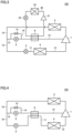
Fig. 1 is a block diagram showing a refrigeration cycle apparatus according to a first embodiment. -
Fig. 2 is a block diagram showing a refrigeration cycle apparatus according to a second embodiment. -
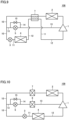
Fig. 3 is a block diagram showing a first modification of the refrigeration cycle apparatus according to the second embodiment. -
Fig. 4 is a block diagram showing a second modification of the refrigeration cycle apparatus according to the second embodiment. -
Fig. 5 is a block diagram showing a third modification of the refrigeration cycle apparatus according to the second embodiment. -
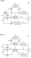
Fig. 6 is a block diagram showing a refrigeration cycle apparatus according to a third embodiment. -
Fig. 7 is a block diagram showing a first modification of the refrigeration cycle apparatus according to the third embodiment. -
Fig. 8 is a block diagram showing a second modification of the refrigeration cycle apparatus according to the third embodiment. -
Fig. 9 is a block diagram showing a third modification of the refrigeration cycle apparatus according to the third embodiment. -
Fig. 10 is a block diagram showing a refrigeration cycle apparatus according to a fourth embodiment. -
Fig. 11 is a block diagram showing a first modification of the refrigeration cycle apparatus according to the fourth embodiment. -
Fig. 12 is a block diagram showing a second modification of the refrigeration cycle apparatus according to the fourth embodiment. -
Fig. 13 is a block diagram showing a third modification of the refrigeration cycle apparatus according to the fourth embodiment. - Embodiments will be described hereinafter with reference to the drawings, in which the same or corresponding portions are denoted by the same reference numerals and description thereof will not be repeated.
- As shown in
Fig. 1 , arefrigeration cycle apparatus 100 according to a first embodiment includes a first refrigerant circuit and an intermediate pressureinjection flow path 13. The first refrigerant circuit and intermediate pressureinjection flow path 13 are filled with first refrigerant (hereinafter, simply referred to as "refrigerant"). The refrigerant may be any refrigerant.Refrigeration cycle apparatus 100 is suitable for refrigerant having a high specific heat ratio. The specific heat ratio of the refrigerant is, for example, equal to or greater than 1.16. The refrigerant includes, for example, at least one selected from the group consisting of CO2, ammonia (NH3), R32, R434A, R410A, and R407H. - The first refrigerant circuit includes a
compressor 1, acondenser 2, afirst expansion valve 3, and anevaporator 4. The first refrigerant circulates throughcompressor 1,condenser 2,first expansion valve 3, andevaporator 4 in this order. -
Compressor 1 includes a discharge port for discharging the refrigerant having a first pressure, a suction port for suctioning the refrigerant having a second pressure lower than the first pressure, and an intermediate pressure port into which the refrigerant having an intermediate pressure between the first pressure and the second pressure is injected. The discharge port is connected to a refrigerant inflow portion ofcondenser 2. The suction port is connected to a refrigerant outflow portion ofevaporator 4. The intermediate pressure port is connected to a below-described second end of intermediate pressureinjection flow path 13. -
Compressor 1 is, for example, a multistage compressor.Compressor 1 includes a high-pressure-side compression unit connected to the discharge port, a low-pressure-side compression unit connected to the suction port, and an intermediate pressure chamber connected to the intermediate pressure port and connecting the high-pressure-side compression unit and the low-pressure-side compression unit. In the low-pressure-side compression unit, the refrigerant of the second pressure suctioned from the suction port is adiabatically compressed into refrigerant having an intermediate pressure, which is discharged to the intermediate pressure chamber. In the high-pressure-side compression unit, the refrigerant of the intermediate pressure suctioned from the intermediate pressure chamber is adiabatically compressed into refrigerant having a first pressure, which is discharged through the discharge port to the outside ofcompressor 1. - In
condenser 2, the refrigerant discharged from the discharge port ofcompressor 1 condenses.Condenser 2 includes the refrigerant inflow portion into which the refrigerant flows, a heat exchange portion configured to perform heat exchange between the refrigerant and a heat medium such as air, and a refrigerant outflow portion out of which the refrigerant flows. - In
first expansion valve 3, the refrigerant condensed incondenser 2 expands adiabatically.First expansion valve 3 is, for example, an electronic expansion valve. Inevaporator 4, the refrigerant decompressed infirst expansion valve 3 evaporates.Evaporator 4 includes a refrigerant inflow portion into which the refrigerant flows, a heat exchange portion configured to perform heat exchange between the refrigerant and a heat medium such as air, and the refrigerant outflow portion out of which the refrigerant flows. The refrigerant evaporated inevaporator 4 is suctioned into the suction port ofcompressor 1. - In the first refrigerant circuit, a refrigerant flow path that connects the refrigerant outflow portion of
condenser 2 andfirst expansion valve 3 is referred to as "first flow path 10", a flow path that connectsfirst expansion valve 3 and the refrigerant inflow portion ofevaporator 4 is referred to as "second flow path 11", and a flow path that connects the refrigerant outflow portion ofevaporator 4 and the suction port ofcompressor 1 is referred to as "third flow path 12". - In the first refrigerant circuit,
condenser 2 is a heat-source-side heat exchanger andevaporator 4 is a load-side heat exchanger, for example. In this case,compressor 1,condenser 2,first expansion valve 3, asecond expansion valve 5,first flow path 10, intermediate pressureinjection flow path 13, abypass flow path 14, and anadjustment valve 15, and a part of each ofsecond flow path 11 andthird flow path 12 are arranged in a heat-source-side unit (outdoor unit).Evaporator 4, and another part of each ofsecond flow path 11 andthird flow path 12 are arranged in a load-side unit (indoor unit). A remaining part of each ofsecond flow path 11 andthird flow path 12 is arranged in a pipe that connects the heat-source-side unit and the load-side unit. - Intermediate pressure
injection flow path 13 includessecond expansion valve 5,bypass flow path 14 that bypasses the second expansion valve, andadjustment valve 15 configured to adjust a flow rate of the refrigerant flowing inbypass flow path 14. A first end of intermediate pressureinjection flow path 13 is connected tofirst flow path 10 of the first refrigerant circuit. The second end of intermediate pressureinjection flow path 13 is connected to the intermediate pressure port of the compressor. When a degree of opening ofsecond expansion valve 5 is greater than zero, intermediate pressureinjection flow path 13 returns, tocompressor 1, a part of the refrigerant condensed incondenser 2. - In
second expansion valve 5, the refrigerant flowing in intermediate pressureinjection flow path 13 expands adiabatically.Second expansion valve 5 is, for example, an electronic expansion valve. The degree of opening ofsecond expansion valve 5 is controlled by a below-describedcontroller 210 to increase and decrease. A flow rate of the refrigerant flowing in intermediate pressureinjection flow path 13 increases and decreases in accordance with the degree of opening ofsecond expansion valve 5. When the degree of opening ofsecond expansion valve 5 is zero, i.e., whensecond expansion valve 5 is closed, the whole of the refrigerant condensed incondenser 2 flows intofirst expansion valve 3 and the refrigerant does not flow in intermediate pressureinjection flow path 13. When the degree of opening ofsecond expansion valve 5 is greater than zero, a part of the refrigerant condensed incondenser 2 flows in intermediate pressureinjection flow path 13. - One end of
bypass flow path 14 is connected to a portion of intermediate pressureinjection flow path 13 located on the upstream side ofsecond expansion valve 5. The other end ofbypass flow path 14 is connected to a portion of intermediate pressureinjection flow path 13 located on the downstream side ofsecond expansion valve 5. -
Adjustment valve 15 may be arbitrarily configured as long asadjustment valve 15 can adjust the flow rate of the refrigerant flowing inbypass flow path 14. However,adjustment valve 15 is, for example, an on-off valve, and is a solenoid valve as a more specific example. A degree of opening ofadjustment valve 15 when a temperature of the high-pressure refrigerant discharged from the discharge port is higher than a determination value is higher than the degree of opening ofadjustment valve 15 when the temperature of the high-pressure refrigerant discharged from the discharge port is equal to or lower than the determination value. -
Refrigeration cycle apparatus 100 further includes atemperature sensor 200 configured to measure a temperature (discharge temperature) of the refrigerant discharged fromcompressor 1, andcontroller 210 configured to control the degrees of opening ofsecond expansion valve 5 andadjustment valve 15 in accordance with the discharge temperature.Temperature sensor 200 is, for example, a thermistor. -
Controller 210 includes a not-shown central processing unit (CPU), a not-shown memory (read only memory (ROM) and random access memory (RAM)), a not-shown input/output buffer for inputting and outputting various signals, and the like. The CPU loads programs stored in the ROM to the RAM or the like and executes the programs. The programs stored in the ROM are programs describing process procedures ofcontroller 210. In accordance with these programs,controller 210 controlssecond expansion valve 5 andadjustment valve 15. The above-described control is not limited to processing by software, and can also be performed by dedicated hardware (electronic circuit). -
Controller 210 determines whether the discharge temperature measured bytemperature sensor 200 is equal to or lower than the determination value. While the discharge temperature is equal to or lower than the determination value,controller 210 maintainssecond expansion valve 5 andadjustment valve 15 in a closed state. When the discharge temperature becomes higher than the determination value,controller 210 openssecond expansion valve 5. When the discharge temperature is still higher than the determination value aftersecond expansion valve 5 is fully opened,controller 210 opensadjustment valve 15. While the discharge temperature is higher than the determination value,controller 210 maintainssecond expansion valve 5 andadjustment valve 15 in an open state. - When the discharge temperature again becomes equal to or lower than the determination value,
controller 210 closessecond expansion valve 5.Controller 210 continuously or intermittently performs the above-described determination whilerefrigeration cycle apparatus 100 is operating. - When the discharge temperature becomes higher than the determination value,
controller 210 may open at least one ofsecond expansion valve 5 andadjustment valve 15, or may opensecond expansion valve 5 andadjustment valve 15 at the same time. - The functions and effects of
refrigeration cycle apparatus 100 will be described based on comparison with refrigeration cycle apparatuses according to comparative examples. A refrigeration cycle apparatus according to Comparative Example 1 is different fromrefrigeration cycle apparatus 100 only in that an injection flow path does not includebypass flow path 14 andadjustment valve 15. A refrigeration cycle apparatus according to Comparative Example 2 is different fromrefrigeration cycle apparatus 100 in that the refrigeration cycle apparatus according to Comparative Example 2 does not include an injection flow path, and a second expansion valve,bypass flow path 14 andadjustment valve 15 that are included in the injection flow path. - Also in the refrigeration cycle apparatus according to Comparative Example 1, a second expansion valve is opened when a discharge temperature becomes higher than a determination value. As a result, a part of the refrigerant condensed in a condenser flows into the injection flow path. The refrigerant having flown into the injection flow path expands adiabatically and is decompressed into gas-liquid two-phase refrigerant having an intermediate pressure in the second expansion valve. The gas-liquid two-phase refrigerant is injected from an intermediate pressure port of
compressor 1 into an intermediate pressure chamber. - In the refrigeration cycle apparatus according to Comparative Example 1, in the case where refrigerant having a high specific heat ratio is filled, it is difficult to decrease the discharge temperature to be equal to or lower than the determination value, even when the second expansion valve is fully opened. For example, when the specific heat ratio of the refrigerant is equal to or greater than 1.16, an evaporation temperature can be -10°C, a condensation temperature can be 45°C and a suction superheat can be 10K during operation of the refrigeration cycle apparatus according to Comparative Example 1. Under these operating conditions, the discharge temperature exceeds 100°C. Therefore, in the case where the determination value is 100°C as described above, it is difficult to decrease the discharge temperature to be equal to or lower than the determination value, even when the second expansion valve is fully opened.
- In contrast, in
refrigeration cycle apparatus 100, intermediate pressureinjection flow path 13 includesbypass flow path 14 andadjustment valve 15. Therefore, when comparison is made betweenrefrigeration cycle apparatus 100 and the refrigeration cycle apparatus according to Comparative Example 1, assuming that the degree of opening ofsecond expansion valve 5 is equivalent, the flow rate of the refrigerant flowing in intermediate pressureinjection flow path 13 ofrefrigeration cycle apparatus 100 whenadjustment valve 15 is further opened is greater than a flow rate of the refrigerant flowing in the intermediate pressure injection flow path of the refrigeration cycle apparatus according to Comparative Example 1. Therefore, as compared with the refrigeration cycle apparatus according to Comparative Example 1,refrigeration cycle apparatus 100 can reliably suppress an increase in discharge temperature even when the refrigerant having a high specific heat ratio is used. - In addition, as compared with the refrigeration cycle apparatus according to Comparative Example 1, a time period to cause the refrigerant to flow in intermediate pressure
injection flow path 13 in order to suppress an increase in discharge temperature can be shortened inrefrigeration cycle apparatus 100. That is, as compared with the refrigeration cycle apparatus according to Comparative Example 1, a time period from detection of an increase in discharge temperature to restart of the normal operation can be shortened inrefrigeration cycle apparatus 100. Therefore, as compared with the refrigeration cycle apparatus according to Comparative Example 1, a decrease in capability caused by the process for suppressing an increase in discharge temperature is suppressed inrefrigeration cycle apparatus 100. - In the refrigeration cycle apparatus according to Comparative Example 2, a so-called liquid back state in which liquid-phase refrigerant is suctioned into a compressor is implemented in order to suppress an increase in discharge temperature. In the refrigeration cycle apparatus according to Comparative Example 2, as a specific heat ratio of the filled refrigerant becomes higher, a flow rate of the liquid-phase refrigerant to be suctioned into the compressor in the above-described liquid back state becomes greater. When a large amount of liquid-phase refrigerant is returned to the compressor, dilution of oil in the compressor occurs, which leads to a decrease in reliability of the compressor.
- In contrast, in
refrigeration cycle apparatus 100, an increase in discharge temperature can be suppressed without implementing the so-called liquid back state. Therefore, the reliability ofcompressor 1 is higher inrefrigeration cycle apparatus 100 than in the refrigeration cycle apparatus according to Comparative Example 2. - The first refrigerant circuit may include a switching unit such as, for example, a four-wary valve configured to switch a flow direction of the refrigerant. In such
refrigeration cycle apparatus 100, the switching unit switches between a cooling operation in which the heat-source-side heat exchanger functions as a condenser and the load-side heat exchanger functions as an evaporator and a heating operation in which the heat-source-side heat exchanger functions as an evaporator and the load-side heat exchanger functions as a condenser. - As shown in
Fig. 2 , arefrigeration cycle apparatus 101 according to a second embodiment is configured basically similarly torefrigeration cycle apparatus 100 according to the first embodiment. However,refrigeration cycle apparatus 101 is different fromrefrigeration cycle apparatus 100 in that intermediate pressureinjection flow path 13 further includesfirst cooling unit 6. InFig. 2 ,temperature sensor 200 andcontroller 210 are not shown. - In
first cooling unit 6, the refrigerant decompressed insecond expansion valve 5 is cooled. First coolingunit 6 is arranged betweensecond expansion valve 5 and the intermediate pressure port ofcompressor 1 in intermediate pressureinjection flow path 13. Preferably,first cooling unit 6 is arranged between the above-described other end ofbypass flow path 14 and the intermediate pressure port ofcompressor 1 in intermediate pressureinjection flow path 13. In other words, the other end ofbypass flow path 14 is connected to a portion of intermediate pressureinjection flow path 13 located on the downstream side ofsecond expansion valve 5 and located on the upstream side offirst cooling unit 6. The other end ofbypass flow path 14 may be connected to a portion of intermediate pressureinjection flow path 13 located on the downstream side offirst cooling unit 6. - First cooling
unit 6 includes a refrigerant inflow portion into which the refrigerant flows, a heat exchange portion configured to perform heat exchange between the refrigerant and a cold source such as air, and a refrigerant outflow portion out of which the refrigerant flows. The refrigerant is cooled infirst cooling unit 6, and thereby, a degree of dryness of the refrigerant decreases. The refrigerant cooled infirst cooling unit 6 is suctioned from the intermediate pressure port ofcompressor 1. - Since
refrigeration cycle apparatus 101 includes intermediate pressureinjection flow path 13 includingbypass flow path 14 andadjustment valve 15,refrigeration cycle apparatus 101 can also produce effects similar to those ofrefrigeration cycle apparatus 100. - Furthermore, in
refrigeration cycle apparatus 101, intermediate pressureinjection flow path 13 includesfirst cooling unit 6. Inrefrigeration cycle apparatus 101 as well, when the discharge temperature becomes higher than the determination value,second expansion valve 5 is opened. As a result, a part of the refrigerant condensed incondenser 2 flows into intermediate pressureinjection flow path 13. The refrigerant having flown into intermediate pressureinjection flow path 13 expands adiabatically and is decompressed into gas-liquid two-phase refrigerant having an intermediate pressure insecond expansion valve 5. The gas-liquid two-phase refrigerant is cooled by the cold source infirst cooling unit 6, to thereby obtain gas-liquid two-phase refrigerant having a low temperature. The gas-liquid two-phase refrigerant having a low temperature is injected from the intermediate pressure port ofcompressor 1 into the intermediate pressure chamber. - Therefore, a temperature of the refrigerant injected from the intermediate pressure port of
compressor 1 into the intermediate pressure chamber inrefrigeration cycle apparatus 101 is lower than a temperature of the refrigerant injected from the intermediate pressure port of the compressor into the intermediate pressure chamber inrefrigeration cycle apparatus 100. Therefore, as compared withrefrigeration cycle apparatus 100, inrefrigeration cycle apparatus 101, an increase in discharge temperature can be suppressed even when a flow rate of the refrigerant in intermediate pressureinjection flow path 13 is not small. That is, as compared withrefrigeration cycle apparatus 100, inrefrigeration cycle apparatus 101, an increase in discharge temperature can be suppressed even when a specific heat ratio of the filled refrigerant is high. -
Figs. 3 to 5 are block diagrams showing first to third modifications ofrefrigeration cycle apparatus 101 shown inFig. 2 . InFigs. 3 to 5 ,temperature sensor 200 andcontroller 210 are not shown. - A
refrigeration cycle apparatus 102 shown inFig. 3 is configured basically similarly torefrigeration cycle apparatus 101. However,refrigeration cycle apparatus 102 is different fromrefrigeration cycle apparatus 101 in thatrefrigeration cycle apparatus 102 further includes a secondrefrigerant circuit 20 in which second refrigerant circulates, and the cold source for the refrigerant infirst cooling unit 6 is the second refrigerant. - The second refrigerant may be any refrigerant. A specific heat ratio of the second refrigerant is, for example, lower than the specific heat ratio of the above-described first refrigerant. The specific heat ratio of the second refrigerant may be, for example, equal to the specific heat ratio of the above-described first refrigerant.
- Second
refrigerant circuit 20 includes asecond compressor 21, asecond condenser 22, athird expansion valve 23, andfirst cooling unit 6. The second refrigerant circulates throughsecond compressor 21,second condenser 22,third expansion valve 23, andfirst cooling unit 6 in this order. Infirst cooling unit 6, the second refrigerant flowing in secondrefrigerant circuit 20 absorbs vaporization heat from the refrigerant flowing in intermediate pressureinjection flow path 13, and evaporates. In this way,first cooling unit 6 cools the refrigerant flowing in intermediate pressureinjection flow path 13 by the second refrigerant flowing in secondrefrigerant circuit 20. Operating conditions ofsecond compressor 21 andthird expansion valve 23 are set such that the second refrigerant flowing infirst cooling unit 6 can sufficiently cool the refrigerant flowing in intermediate pressureinjection flow path 13. - Since
refrigeration cycle apparatus 102 includes intermediate pressureinjection flow path 13 includingbypass flow path 14,adjustment valve 15 andfirst cooling unit 6 as described above,refrigeration cycle apparatus 102 can also produce effects similar to those ofrefrigeration cycle apparatus 101. - A
refrigeration cycle apparatus 103 shown inFig. 4 is configured basically similarly torefrigeration cycle apparatus 101. However,refrigeration cycle apparatus 103 is different fromrefrigeration cycle apparatus 101 in thatfirst cooling unit 6 is an internal heat exchanger and the cold source for the refrigerant flowing in intermediate pressureinjection flow path 13 infirst cooling unit 6 is the refrigerant flowing betweenfirst expansion valve 3 and the suction port ofcompressor 1. - In
first cooling unit 6 shown inFig. 4 , heat exchange is performed between the refrigerant flowing in intermediate pressureinjection flow path 13 and the refrigerant flowing insecond flow path 11. Inrefrigeration cycle apparatus 103, when the discharge temperature is higher than the determination value,second expansion valve 5 is opened. At this time, the degree of opening ofsecond expansion valve 5 is set such that an amount of decrease in pressure of the refrigerant insecond expansion valve 5 is smaller than an amount of decrease in pressure of the refrigerant infirst expansion valve 3. For example,second expansion valve 5 is fully opened. As a result, the flow rate of the refrigerant flowing throughsecond expansion valve 5 is maximized and the temperature of the refrigerant having adiabatically expanded insecond expansion valve 5 becomes higher than the temperature of the refrigerant having adiabatically expanded infirst expansion valve 3. Therefore, infirst cooling unit 6, a relatively large amount of refrigerant flowing in intermediate pressureinjection flow path 13 is cooled by the refrigerant flowing insecond flow path 11. - Since
refrigeration cycle apparatus 103 includes intermediate pressureinjection flow path 13 includingbypass flow path 14,adjustment valve 15 andfirst cooling unit 6 as described above,refrigeration cycle apparatus 103 can also produce effects similar to those ofrefrigeration cycle apparatus 101. - A
refrigeration cycle apparatus 104 shown inFig. 5 is configured basically similarly torefrigeration cycle apparatus 103. However,refrigeration cycle apparatus 104 is different fromrefrigeration cycle apparatus 103 in that the cold source for the refrigerant flowing in intermediate pressureinjection flow path 13 infirst cooling unit 6 is the refrigerant flowing betweenevaporator 4 and the suction port ofcompressor 1. - In
first cooling unit 6 shown inFig. 5 , heat exchange is performed between the refrigerant flowing in intermediate pressureinjection flow path 13 and the refrigerant flowing inthird flow path 12. Inrefrigeration cycle apparatus 104, when the discharge temperature is higher than the determination value,second expansion valve 5 is opened. For example,second expansion valve 5 is fully opened. As a result, the flow rate of the refrigerant flowing throughsecond expansion valve 5 is maximized. The temperature of the refrigerant having adiabatically expanded insecond expansion valve 5 becomes higher than the temperature of the refrigerant having adiabatically expanded infirst expansion valve 3 and evaporated inevaporator 4. Therefore, infirst cooling unit 6, a relatively large amount of refrigerant flowing in intermediate pressureinjection flow path 13 is cooled by the refrigerant flowing inthird flow path 12. - Since
refrigeration cycle apparatus 104 includes intermediate pressureinjection flow path 13 includingbypass flow path 14,adjustment valve 15 andfirst cooling unit 6 as described above,refrigeration cycle apparatus 104 can also produce effects similar to those ofrefrigeration cycle apparatus 101. - As shown in
Fig. 6 , arefrigeration cycle apparatus 105 according to a third embodiment is configured basically similarly torefrigeration cycle apparatus 100 according to the first embodiment. However,refrigeration cycle apparatus 105 is different fromrefrigeration cycle apparatus 100 in that the refrigerant circuit further includes asecond cooling unit 7. -
Second cooling unit 7 cools the refrigerant flowing betweencondenser 2 and the above-described first end of intermediate pressureinjection flow path 13 infirst flow path 10 by a second cold source. Insecond cooling unit 7, the refrigerant condensed incondenser 2 is supercooled.Second cooling unit 7 functions as a supercooler.Second cooling unit 7 is arranged betweencondenser 2 and the above-described first end of intermediate pressureinjection flow path 13 in the refrigerant circuit.Second cooling unit 7 includes a refrigerant inflow portion into which the refrigerant flows, a heat exchange portion configured to perform heat exchange between the refrigerant and the second cold source such as air, and a refrigerant outflow portion out of which the refrigerant flows. - When the degree of opening of
second expansion valve 5 is zero, i.e., whensecond expansion valve 5 is closed, the whole of the refrigerant condensed incondenser 2 and supercooled insecond cooling unit 7 flows intofirst expansion valve 3 and the refrigerant does not flow in intermediate pressureinjection flow path 13. When the degree of opening ofsecond expansion valve 5 is greater than zero, a part of the refrigerant condensed incondenser 2 and supercooled insecond cooling unit 7 flows in intermediate pressureinjection flow path 13. - Since
refrigeration cycle apparatus 105 includes intermediate pressureinjection flow path 13 includingbypass flow path 14 andadjustment valve 15,refrigeration cycle apparatus 105 can produce effects similar to those ofrefrigeration cycle apparatus 100. - Furthermore, since the refrigerant circuit includes
second cooling unit 7, a degree of supercooling of the refrigerant flowing intofirst expansion valve 3 inrefrigeration cycle apparatus 105 is higher than that inrefrigeration cycle apparatus 100. As a result, the performance ofrefrigeration cycle apparatus 105 is higher than the performance ofrefrigeration cycle apparatus 100. -
Figs. 7 to 9 are block diagrams showing first to third modifications ofrefrigeration cycle apparatus 105 shown inFig. 6 . InFigs. 7 to 9 ,temperature sensor 200 andcontroller 210 are not shown. - A
refrigeration cycle apparatus 106 shown inFig. 7 is configured basically similarly torefrigeration cycle apparatus 105. However,refrigeration cycle apparatus 106 is different fromrefrigeration cycle apparatus 105 in thatrefrigeration cycle apparatus 106 further includes a thirdrefrigerant circuit 30 in which third refrigerant circulates, and the cold source (second cold source) for the refrigerant flowing infirst flow path 10 insecond cooling unit 7 is the third refrigerant. - Third
refrigerant circuit 30 includes athird compressor 31, athird condenser 32, afourth expansion valve 33, andsecond cooling unit 7. The third refrigerant circulates throughthird compressor 31,third condenser 32,fourth expansion valve 33, andsecond cooling unit 7 in this order. Insecond cooling unit 7, the third refrigerant flowing in thirdrefrigerant circuit 30 absorbs vaporization heat from the refrigerant flowing infirst flow path 10, and evaporates. In this way,second cooling unit 7 cools the refrigerant flowing infirst flow path 10 by the third refrigerant flowing in thirdrefrigerant circuit 30. Operating conditions ofthird compressor 31 andfourth expansion valve 33 are set such that the third refrigerant flowing insecond cooling unit 7 can sufficiently cool the refrigerant flowing infirst flow path 10. The third refrigerant may be any refrigerant. A specific heat ratio of the third refrigerant is, for example, lower than the specific heat ratio of the above-described first refrigerant. The specific heat ratio of the third refrigerant may be, for example, equal to the specific heat ratio of the above-described first refrigerant. - A
refrigeration cycle apparatus 107 shown inFig. 8 is configured basically similarly torefrigeration cycle apparatus 105. However,refrigeration cycle apparatus 107 is different fromrefrigeration cycle apparatus 105 in that the cold source for the refrigerant flowing infirst flow path 10 insecond cooling unit 7 is the refrigerant flowing betweenfirst expansion valve 3 and the suction port ofcompressor 1. Insecond cooling unit 7, heat exchange is performed between the refrigerant flowing infirst flow path 10 and the refrigerant flowing insecond flow path 11. - A
refrigeration cycle apparatus 108 shown inFig. 9 is configured basically similarly torefrigeration cycle apparatus 105. However,refrigeration cycle apparatus 108 is different fromrefrigeration cycle apparatus 103 in that the cold source for the refrigerant flowing infirst flow path 10 insecond cooling unit 7 is the refrigerant flowing betweenevaporator 4 and the suction port ofcompressor 1. Insecond cooling unit 7, heat exchange is performed between the refrigerant flowing infirst flow path 10 and the refrigerant flowing inthird flow path 12. - Since each of
refrigeration cycle apparatuses Figs. 7 to 9 is configured such that the refrigerant circuit further includessecond cooling unit 7, each ofrefrigeration cycle apparatuses refrigeration cycle apparatus 105. - As shown in
Fig. 10 , arefrigeration cycle apparatus 109 according to a fourth embodiment is configured basically similarly torefrigeration cycle apparatus 100 according to the first embodiment. However,refrigeration cycle apparatus 109 is different fromrefrigeration cycle apparatus 100 in that intermediate pressureinjection flow path 13 further includesfirst cooling unit 6 and the refrigerant circuit further includessecond cooling unit 7. - First cooling
unit 6 ofrefrigeration cycle apparatus 109 is configured similarly tofirst cooling unit 6 ofrefrigeration cycle apparatus 101 shown inFig. 2 .Second cooling unit 7 ofrefrigeration cycle apparatus 109 is configured similarly tosecond cooling unit 7 ofrefrigeration cycle apparatus 105 shown inFig. 6 . - Since
refrigeration cycle apparatus 109 includes intermediate pressureinjection flow path 13 includingbypass flow path 14 andadjustment valve 15,refrigeration cycle apparatus 109 can produce effects similar to those ofrefrigeration cycle apparatus 100. - Furthermore, since
refrigeration cycle apparatus 109 further includesfirst cooling unit 6 shown inFig. 2 andsecond cooling unit 7 shown inFig. 6 ,refrigeration cycle apparatus 109 can produce the effects ofrefrigeration cycle apparatus 101 and the effects ofrefrigeration cycle apparatus 104 at the same time. -
Figs. 11 to 13 are block diagrams showing first to third modifications ofrefrigeration cycle apparatus 109 shown inFig. 10 . InFigs. 11 to 13 ,temperature sensor 200 andcontroller 210 are not shown. - A
refrigeration cycle apparatus 110 shown inFig. 11 is configured basically similarly torefrigeration cycle apparatus 109. However,refrigeration cycle apparatus 110 is different fromrefrigeration cycle apparatus 109 in thatfirst cooling unit 6 is configured similarly tofirst cooling unit 6 shown inFig. 3 . - A
refrigeration cycle apparatus 111 shown inFig. 12 is configured basically similarly torefrigeration cycle apparatus 109. However,refrigeration cycle apparatus 111 is different fromrefrigeration cycle apparatus 109 in thatfirst cooling unit 6 is configured similarly tofirst cooling unit 6 shown inFig. 4 andsecond cooling unit 7 is configured similarly tosecond cooling unit 7 shown inFig. 7 . - A
refrigeration cycle apparatus 112 shown inFig. 13 is configured basically similarly torefrigeration cycle apparatus 111. However,refrigeration cycle apparatus 112 is different fromrefrigeration cycle apparatus 109 in thatfirst cooling unit 6 is configured similarly tofirst cooling unit 6 shown inFig. 5 . - Since each of
refrigeration cycle apparatuses Figs. 11 to 13 includesfirst cooling unit 6 andsecond cooling unit 7 at the same time, each ofrefrigeration cycle apparatuses refrigeration cycle apparatus 109.Second cooling unit 7 in each ofrefrigeration cycle apparatuses second cooling units 7 shown inFigs. 6 to 9 . - Although the embodiments of the present disclosure have been described above, the above-described embodiments can also be variously modified. The scope of the present disclosure is not limited to the above-described embodiments. The scope of the present disclosure is defined by the terms of the claims, and is intended to include any modifications within the scope and meaning equivalent to the terms of the claims.
- 1 compressor; 2 condenser; 3 first expansion valve; 4 evaporator; 5 second expansion valve; 6 cooling unit; 7 second cooling unit; 10 first flow path; 11 second flow path; 12 third flow path; 13 intermediate pressure injection flow path; 14 bypass flow path; 15 adjustment valve; 20 second refrigerant circuit; 21 second compressor; 22 second condenser; 23 third expansion valve; 30 third refrigerant circuit; 31 third compressor; 32 third condenser; 33 fourth expansion valve; 100, 101, 102, 103, 104, 105, 106, 107, 108, 109, 110, 111, 112 refrigeration cycle apparatus; 200 temperature sensor; 210 controller.
Claims (10)
- A refrigeration cycle apparatus comprising:a first refrigerant circuit, the first refrigerant circuit comprising: a compressor; a condenser; a first expansion valve; and an evaporator, refrigerant circulating in the first refrigerant circuit in an order of the compressor, the condenser, the first expansion valve, and the evaporator,
the compressor comprising: a discharge port for discharging the refrigerant having a first pressure; a suction port for suctioning the refrigerant having a second pressure lower than the first pressure; and an intermediate pressure port into which the refrigerant having an intermediate pressure between the first pressure and the second pressure flows; andan intermediate pressure injection flow path comprising: a first end connected between the condenser and the first expansion valve in the first refrigerant circuit; and a second end connected to the intermediate pressure port of the compressor,the intermediate pressure injection flow path being configured to return, to the compressor, a part of the refrigerant flowing out of the condenser,the intermediate pressure injection flow path further comprising: a second expansion valve; a bypass flow path that bypasses the second expansion valve; and an adjustment valve configured to adjust a flow rate of the refrigerant flowing in the bypass flow path. - The refrigeration cycle apparatus according to claim 1, wherein
a degree of opening of the adjustment valve when a temperature of the refrigerant of high pressure discharged from the discharge port is higher than a determination value is higher than the degree of opening when the temperature of the refrigerant of high pressure discharged from the discharge port is equal to or lower than the determination value. - The refrigeration cycle apparatus according to claim 1 or 2, wherein
the intermediate pressure injection flow path comprises a first cooling unit configured to cool, by a cold source, the refrigerant flowing in the intermediate pressure injection flow path. - The refrigeration cycle apparatus according to claim 3, wherein
the cold source is the refrigerant flowing between the first expansion valve and the suction port of the compressor in the first refrigerant circuit. - The refrigeration cycle apparatus according to claim 4, wherein
the cold source is the refrigerant flowing between the evaporator and the suction port of the compressor in the first refrigerant circuit. - The refrigeration cycle apparatus according to claim 3, wherein
the cold source is air. - The refrigeration cycle apparatus according to claim 3, further comprising a second refrigerant circuit in which second refrigerant circulates, wherein the cold source is the second refrigerant.
- The refrigeration cycle apparatus according to any one of claims 1 to 7, wherein
the first refrigerant circuit further comprises a second cooling unit configured to cool, by a second cold source, the refrigerant flowing between the condenser and the first end of the intermediate pressure injection flow path. - The refrigeration cycle apparatus according to any one of claims 1 to 8, wherein
a specific heat ratio of the refrigerant is equal to or greater than 1.16. - The refrigeration cycle apparatus according to any one of claims 1 to 9, wherein
the refrigerant comprises carbon dioxide.
Applications Claiming Priority (1)
| Application Number | Priority Date | Filing Date | Title |
|---|---|---|---|
| PCT/JP2020/027550 WO2022013982A1 (en) | 2020-07-15 | 2020-07-15 | Refrigeration cycle device |
Publications (2)
| Publication Number | Publication Date |
|---|---|
| EP4184077A1 true EP4184077A1 (en) | 2023-05-24 |
| EP4184077A4 EP4184077A4 (en) | 2023-09-13 |
Family
ID=79555307
Family Applications (1)
| Application Number | Title | Priority Date | Filing Date |
|---|---|---|---|
| EP20945603.7A Withdrawn EP4184077A4 (en) | 2020-07-15 | 2020-07-15 | REFRIGERATING CYCLE DEVICE |
Country Status (4)
| Country | Link |
|---|---|
| EP (1) | EP4184077A4 (en) |
| JP (1) | JP7367222B2 (en) |
| CN (1) | CN115867755A (en) |
| WO (1) | WO2022013982A1 (en) |
Families Citing this family (2)
| Publication number | Priority date | Publication date | Assignee | Title |
|---|---|---|---|---|
| WO2024102371A1 (en) * | 2022-11-07 | 2024-05-16 | Johnson Controls Tyco IP Holdings LLP | Energy efficient heat pump systems and methods |
| WO2025141717A1 (en) * | 2023-12-26 | 2025-07-03 | 三菱電機株式会社 | Refrigeration cycle device |
Family Cites Families (15)
| Publication number | Priority date | Publication date | Assignee | Title |
|---|---|---|---|---|
| JP2760221B2 (en) * | 1992-07-28 | 1998-05-28 | ダイキン工業株式会社 | Discharge gas temperature control mechanism of screw compressor |
| JPH08271062A (en) * | 1995-03-31 | 1996-10-18 | Sanyo Electric Co Ltd | Refrigerator |
| JP2001091064A (en) * | 1999-09-20 | 2001-04-06 | Mitsubishi Electric Corp | Refrigeration equipment |
| JP4716832B2 (en) * | 2005-09-26 | 2011-07-06 | 三洋電機株式会社 | Refrigeration equipment |
| CN101666562B (en) * | 2006-03-27 | 2012-10-17 | 三菱电机株式会社 | Refrigerating and air-conditioning plant |
| JP2011133133A (en) * | 2009-12-22 | 2011-07-07 | Daikin Industries Ltd | Refrigerating device |
| WO2011077720A1 (en) * | 2009-12-22 | 2011-06-30 | ダイキン工業株式会社 | Refrigeration device |
| JPWO2014203354A1 (en) | 2013-06-19 | 2017-02-23 | 三菱電機株式会社 | Refrigeration cycle equipment |
| JP6241595B2 (en) * | 2013-08-23 | 2017-12-06 | サンデンホールディングス株式会社 | Air conditioner for vehicles |
| JP2017026238A (en) | 2015-07-24 | 2017-02-02 | 株式会社富士通ゼネラル | Heat pump cycle equipment |
| CN105485767A (en) * | 2015-12-22 | 2016-04-13 | 珠海格力电器股份有限公司 | Multi-split air conditioning system and control method |
| WO2018100711A1 (en) * | 2016-12-01 | 2018-06-07 | 三菱電機株式会社 | Refrigeration device |
| CN110892209B (en) * | 2017-08-04 | 2021-12-28 | 三菱电机株式会社 | Refrigeration cycle device and heat source unit |
| JP6852642B2 (en) * | 2017-10-16 | 2021-03-31 | 株式会社デンソー | Heat pump cycle |
| PL3677855T3 (en) * | 2018-06-07 | 2024-03-18 | Panasonic Intellectual Property Management Co., Ltd. | Refrigeration cycle device and liquid heating device having the same |
-
2020
- 2020-07-15 EP EP20945603.7A patent/EP4184077A4/en not_active Withdrawn
- 2020-07-15 CN CN202080102936.9A patent/CN115867755A/en active Pending
- 2020-07-15 WO PCT/JP2020/027550 patent/WO2022013982A1/en not_active Ceased
- 2020-07-15 JP JP2022536049A patent/JP7367222B2/en active Active
Also Published As
| Publication number | Publication date |
|---|---|
| EP4184077A4 (en) | 2023-09-13 |
| WO2022013982A1 (en) | 2022-01-20 |
| JPWO2022013982A1 (en) | 2022-01-20 |
| JP7367222B2 (en) | 2023-10-23 |
| CN115867755A (en) | 2023-03-28 |
Similar Documents
| Publication | Publication Date | Title |
|---|---|---|
| US8424326B2 (en) | Refrigerant vapor compression system and method of transcritical operation | |
| JP5318099B2 (en) | Refrigeration cycle apparatus and control method thereof | |
| EP2995885B1 (en) | Binary refrigeration device | |
| US8561425B2 (en) | Refrigerant vapor compression system with dual economizer circuits | |
| US9951974B2 (en) | Flash tank economizer cycle control | |
| JP2011052884A (en) | Refrigerating air conditioner | |
| US10180269B2 (en) | Refrigeration device | |
| EP2068093A1 (en) | Refrigeration device | |
| EP3617617B1 (en) | Outdoor unit and method for controlling same | |
| EP2068095A1 (en) | Refrigeration device | |
| US12085320B2 (en) | Heat source unit and refrigeration apparatus | |
| EP4184077A1 (en) | Refrigeration cycle device | |
| EP3282208A1 (en) | Refrigeration apparatus | |
| JPH09159288A (en) | Refrigeration equipment | |
| EP3306238B1 (en) | Control device, refrigerant circuit system and control method | |
| JP7466645B2 (en) | Refrigeration Cycle Equipment | |
| JP2017129320A (en) | Refrigeration equipment | |
| JP2013217602A (en) | Heat source device, refrigeration air conditioner, and control device | |
| WO2024095446A1 (en) | Refrigeration cycle device | |
| EP4113035B1 (en) | Freezing device, freezing system, and control method of freezing device | |
| EP1235043A1 (en) | Refrigerating device | |
| US20050274140A1 (en) | Refrigeration cycle | |
| JP2002031417A (en) | Refrigerating apparatus | |
| JP2025011999A (en) | Refrigerating machine and method for controlling the same | |
| WO2020202519A1 (en) | Refrigeration cycle device |
Legal Events
| Date | Code | Title | Description |
|---|---|---|---|
| STAA | Information on the status of an ep patent application or granted ep patent |
Free format text: STATUS: THE INTERNATIONAL PUBLICATION HAS BEEN MADE |
|
| PUAI | Public reference made under article 153(3) epc to a published international application that has entered the european phase |
Free format text: ORIGINAL CODE: 0009012 |
|
| STAA | Information on the status of an ep patent application or granted ep patent |
Free format text: STATUS: REQUEST FOR EXAMINATION WAS MADE |
|
| 17P | Request for examination filed |
Effective date: 20221114 |
|
| AK | Designated contracting states |
Kind code of ref document: A1 Designated state(s): AL AT BE BG CH CY CZ DE DK EE ES FI FR GB GR HR HU IE IS IT LI LT LU LV MC MK MT NL NO PL PT RO RS SE SI SK SM TR |
|
| A4 | Supplementary search report drawn up and despatched |
Effective date: 20230814 |
|
| RIC1 | Information provided on ipc code assigned before grant |
Ipc: F25B 31/00 20060101ALI20230808BHEP Ipc: F25B 40/02 20060101ALI20230808BHEP Ipc: F25B 40/00 20060101ALI20230808BHEP Ipc: F25B 1/10 20060101ALI20230808BHEP Ipc: F25B 5/02 20060101ALI20230808BHEP Ipc: F25B 1/00 20060101AFI20230808BHEP |
|
| DAV | Request for validation of the european patent (deleted) | ||
| DAX | Request for extension of the european patent (deleted) | ||
| STAA | Information on the status of an ep patent application or granted ep patent |
Free format text: STATUS: THE APPLICATION HAS BEEN WITHDRAWN |
|
| 18W | Application withdrawn |
Effective date: 20240903 |