EP4184065B1 - Innenraumeinheit - Google Patents
Innenraumeinheit Download PDFInfo
- Publication number
- EP4184065B1 EP4184065B1 EP22207446.0A EP22207446A EP4184065B1 EP 4184065 B1 EP4184065 B1 EP 4184065B1 EP 22207446 A EP22207446 A EP 22207446A EP 4184065 B1 EP4184065 B1 EP 4184065B1
- Authority
- EP
- European Patent Office
- Prior art keywords
- arm
- holder
- casing
- panel
- main body
- Prior art date
- Legal status (The legal status is an assumption and is not a legal conclusion. Google has not performed a legal analysis and makes no representation as to the accuracy of the status listed.)
- Active
Links
Images



Classifications
-
- F—MECHANICAL ENGINEERING; LIGHTING; HEATING; WEAPONS; BLASTING
- F24—HEATING; RANGES; VENTILATING
- F24F—AIR-CONDITIONING; AIR-HUMIDIFICATION; VENTILATION; USE OF AIR CURRENTS FOR SCREENING
- F24F1/00—Room units for air-conditioning, e.g. separate or self-contained units or units receiving primary air from a central station
- F24F1/0007—Indoor units, e.g. fan coil units
-
- F—MECHANICAL ENGINEERING; LIGHTING; HEATING; WEAPONS; BLASTING
- F24—HEATING; RANGES; VENTILATING
- F24F—AIR-CONDITIONING; AIR-HUMIDIFICATION; VENTILATION; USE OF AIR CURRENTS FOR SCREENING
- F24F13/00—Details common to, or for air-conditioning, air-humidification, ventilation or use of air currents for screening
- F24F13/20—Casings or covers
-
- F—MECHANICAL ENGINEERING; LIGHTING; HEATING; WEAPONS; BLASTING
- F24—HEATING; RANGES; VENTILATING
- F24F—AIR-CONDITIONING; AIR-HUMIDIFICATION; VENTILATION; USE OF AIR CURRENTS FOR SCREENING
- F24F1/00—Room units for air-conditioning, e.g. separate or self-contained units or units receiving primary air from a central station
- F24F1/0007—Indoor units, e.g. fan coil units
- F24F1/0043—Indoor units, e.g. fan coil units characterised by mounting arrangements
- F24F1/0057—Indoor units, e.g. fan coil units characterised by mounting arrangements mounted in or on a wall
Definitions
- Japanese Unexamined Patent Application, First Publication No. H7-260193 discloses a panel attachment structure for attaching a panel (inlet panel) to an opening portion of a casing of an indoor unit in a manner of being able to be opened and closed.
- a second arm having a rotation center positioned on an outer side of the casing slides with respect to a first arm inside the casing so that the inlet panel provided in the second arm is opened and closed.
- the present invention has been made in order to resolve the foregoing problems, and an object thereof is to provide an indoor unit in which arms are easily attached and detached with respect to a casing and a good appearance is not impaired when an inlet panel is closed.
- an indoor unit as defined in claim 1 includes: a casing having a front surface and holder accommodation portions opening on the front surface and recessed so as to slope upward approaching toward a back side of the casing; arm holders which are inserted into the holder accommodation portions from a front side of the casing and which are installed inside of the holder accommodation portions so as to be detachable therefrom; arms which are inserted into the holder accommodation portions from the front side of the casing and each of which a first end is held by the arm holder so that the arm is allowed to turn around an axis extending in a longitudinal direction of the casing; and an inlet panel to which a second end of each of the arms is fixed.
- the range of movement of the arms around the axis is set between a closed position where the inlet panel is disposed in a manner of overlapping the front surface of the casing and openings of the holder accommodation portions are closed by the inlet panel, and an open position where the inlet panel is disposed forward and upward from the front surface of the casing and the front surface of the casing is exposed.
- An indoor unit is an apparatus which is provided indoors and performs indoor-air conditioning through heat exchange between a refrigerant dealing with an outdoor unit provided outdoors and indoor air.
- An air conditioning apparatus is constituted of an indoor unit and an outdoor unit.
- an indoor unit 100 includes a casing 1, a fan 2, a heat exchanger 3, a Filter part 4, a control unit 5, an arm holder 6, a bolt 7, an arm 8 and an inlet panel 9.
- the casing 1 is constituted of a plurality of panels and installed on an indoor wall surface W.
- the casing 1 forms an outer shell of the indoor unit 100.
- the casing 1 accommodates various equipment and defines a space for circulating indoor air on an inner side.
- the casing 1 has a back surface panel 10, a bottom panel 20, a top surface panel 30, a pair of side surface panels 40, a front panel 50, a connection panel 70, and a flap 73.
- the back surface panel 10 is a panel fixed to the indoor wall surface W with a mounting plate or the like (not illustrated) therebetween.
- the back surface panel 10 has a back surface 11 spreading along the wall surface W and facing the wall surface W.
- an installation direction Di a direction in which the back surface 11 of the back surface panel 10 faces the wall surface W face each other. Therefore, the installation direction Di is a direction perpendicular to the wall surface W.
- the back surface 11 has an oblong shape having a direction parallel to the wall surface W, of a horizontal direction when viewed from the foreside Dif (front), as a longitudinal direction.
- the bottom panel 20 is connected to a lower edge of the back surface panel 10 and spreading in a direction intersecting the wall surface W.
- the bottom panel 20 according to the present embodiment spreads in the horizontal direction and is integrally connected to the back surface panel 10 in a manner of standing upright from the back surface panel 10.
- the bottom panel 20 has a bottom surface 21 spreading in the horizontal direction and facing below.
- the bottom surface 21 spreads in a direction perpendicular to a spreading direction of the back surface 11.
- the top surface panel 30 has a head step 31 spreading in the horizontal direction and directed to the upward side.
- the head step 31 spreads in a direction perpendicular to the spreading direction of the back surface 11.
- an end edge (side) on the head step 31 on the foreside Dif becomes a top edge 1a of the casing 1.
- the top edge 1a is positioned on the furthest upward side in the casing 1.
- a direction in which the bottom panel 20 and the top surface panel 30 face each other will be referred to as "a vertical direction Dv”.
- One side, of both sides in the vertical direction Dv, in a direction directed to the top surface panel 30 from the bottom panel 20 will be simply referred to as “an upside Dvu”, and the other side on a side opposite thereto will be simply referred to as “a downside Dvd”. Therefore, the vertical direction Dv matches with the direction of gravity.
- the bottom surface 21 of the bottom panel 20 according to the present embodiment has an oblong shape having a direction parallel to the wall surface W, of the horizontal direction when viewed from the downside Dvd (below), as the longitudinal direction.
- the head step 31 of the top surface panel 30 according to the present embodiment has an oblong shape having a direction parallel to the wall surface W, of the horizontal direction when viewed from the upside Dvu (above), as the longitudinal direction.
- a plurality of suctioning ports 32 for suctioning indoor air are formed in the top surface panel 30. That is, the top surface panel 30 has the plurality of suctioning ports 32.
- the plurality of suctioning ports 32 are arranged at equal intervals in the horizontal direction.
- Each of the suctioning ports 32 penetrates the top surface panel 30 in the vertical direction Dv.
- Each of the suctioning ports 32 has a rectangular shape (oblong shape) when viewed from the upside Dvu.
- the side surface panels 40 is a panel connecting the end edges of the back surface panel 10, the bottom panel 20, and the top surface panel 30 extending in the longitudinal direction to each other.
- a direction that matches with this longitudinal direction will be referred to as "a width direction Dw". Therefore, the width direction Dw is a direction perpendicular to both the installation direction Di and the vertical direction Dv.
- One side surface panel 40 of the pair of side surface panels 40 has a side surface 41 connecting the end edges of the back surface panel 10, the bottom panel 20, and the top surface panel 30 on the one side Dwr to each other and directed to the one side Dwr.
- the other side surface panel 40 of the pair of side surface panels 40 has another side surface 41 connecting the end edges of the back surface panel 10, the bottom panel 20, and the top surface panel 30 on the other side Dwl to each other and directed to the other side Dwl.
- the front panel 50 is disposed on the foreside Dif of the back surface panel 10 and connects the end edges of the top surface panel 30 and the pair of side surface panels 40 on the foreside Dif to each other.
- the front panel 50 spreads parallel to a spreading direction of the back surface panel 10.
- the front panel 50 has a front surface 51 spreading in a direction along the wall surface W and directed to the foreside Dif.
- the pair of holder accommodation portions 52 are arranged in the width direction Dw.
- One holder accommodation portion 52 of the pair of holder accommodation portions 52 is disposed on the one side Dwr of the main opening 53, of the pair of main openings 53 adjacent to each other in the width direction Dw, disposed on the one side Dwr.
- connection panel 70 is a panel disposed on the downside Dvd of the front panel 50 and connecting the end edges of the bottom panel 20 and the pair of side surface panels 40 on the foreside Dif and the end edge of the front panel 50 on the downside Dvd to each other.
- the flap 73 is provided in the discharge port 72 of the connection panel 70 and changes a direction of air discharged through the discharge port 72.
- the flap 73 can shift between a state of covering the discharge port 72 from the foreside Dif and a state of not covering the discharge port 72.
- the flap 73 is provided in the connection panel 70 and supported by a turning shaft (not illustrated) about a turning axis (not illustrated) extending in the width direction Dw in a manner of being able to turn around the turning axis.
- a turning amount of the flap 73 is controlled on the basis of an input signal input from the outside.
- an accommodation space R a space for accommodating various equipment and circulating indoor air is formed by each of the elements constituting the casing 1.
- this space will be referred to as "an accommodation space R".
- the fan 2 is a cross-flow fan which can introduce indoor air into the casing 1.
- the fan 2 extends in the width direction Dw inside the accommodation space R.
- the fan 2 is held by the back surface panel 10 about a rotation shaft (not illustrated) extending in the width direction Dw in a manner of being able to rotate around the rotation shaft.
- the fan 2 rotates inside the accommodation space R so as to suction air through the suctioning ports 32 of the top surface panel 30 and discharge suctioned air through the discharge port 72 of the bottom panel 20.
- a rotation frequency of the fan 2 is controlled on the basis of an input signal input from the outside.
- the heat exchanger 3 performs heat exchange between air introduced into the accommodation space R by the fan 2 and a refrigerant. That is, the heat exchanger 3 cools or warms air introduced into the accommodation space R.
- the heat exchanger 3 is constituted of a heat transfer pipe in which the refrigerant circulates, a plurality of fins through which this heat transfer pipe is inserted in the width direction Dw, and the like.
- the heat exchanger 3 is provided in a manner of surrounding the fan 2 from the upside Dvu inside the accommodation space R.
- the filter part 4 filters impurities such as dust included in air suctioned through the suctioning ports 32 of the top surface panel 30.
- the filter part 4 is disposed on the upside Dvu of the heat exchanger 3 inside the accommodation space R. That is, the filter part 4 is disposed between the casing 1 and the heat exchanger 3. Therefore, the filter part 4 supplies air from which impurities such as dust have been eliminated to the heat exchanger 3.
- the control unit 5 is a device for controlling the turning amount of the flap 73, rotation of the fan 2, and the like.
- the control unit 5 is connected to the flap 73 and the fan 2 by wire or radio.
- the control unit 5 is provided inside the accommodation space R and disposed on the one side Dwr of the fan 2, the heat exchanger 3, and the filter part 4.
- the control unit 5 when the indoor unit 100 includes a sensor (not illustrated) provided in the casing 1, the control unit 5 generates an input signal on the basis of detected information acquired by the sensor. The control unit 5 transmits a generated input signal to the flap 73 or the fan 2.
- the holder accommodation portion 52 of the pair of holder accommodation portions 52 provided in the front panel 50, disposed on the one side Dwr will be described. Description of the holder accommodation portion 52 disposed on the other side Dwl will be omitted.
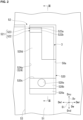
- the holder accommodation portion 52 is a recessed part opening on the front surface 51 of the front panel 50 and recessed toward the upside Dvu approaching toward the backside Dib. As illustrated in FIGS. 2 and 3 , the holder accommodation portion 52 has a holder support portion 520, a first engagement portion 521, and a side wall portion 524.
- the holder accommodation portion 52 includes an opening 50a on the front surface 51.
- the opening 50a according to the present embodiment has a rectangular shape (oblong shape) when viewed from the foreside Dif.
- the longitudinal direction of the opening 50a matches with the vertical direction Dv.
- the holder support portion 520 extends to the upside Dvu as it goes toward the backside Dib from the end edge of the opening 50a on the downside Dvd.
- the holder support portion 520 has a base end surface 520a, a fastening surface 520b, an upper surface 520c, and a support surface 520d.
- the base end surface 520a is a surface connected to the end edge of the opening 50a on the front surface 51 on the downside Dvd and inclined in a manner of being directed to the upside Dvu with respect to the front surface 51.
- a fastening hole 520e opening on the fastening surface 520b and recessed toward the backside Dib from this fastening surface 520b is formed in the holder support portion 520.
- the fastening hole 520e has a screw thread allowing the bolt 7 to be fastened thereto.
- the upper surface 520c is a surface connected to the end edge on the fastening surface 520b on the upside Dvu and spreads in the horizontal direction from the end edge.
- the support surface 520d is a surface connected to the end edge on the upper surface 520c on the backside Dib and inclined in a manner of being directed to the foreside Dif with respect to the upper surface 520c.
- the support surface 520d according to the present embodiment is formed to be inclined, for example by 40° to 50°, with respect to a virtual horizontal plane (spreading direction of the upper surface 520c).
- the first base portion 522 extends in a direction intersecting a spreading direction of the support surface 520d above the support surface 520d.
- the first base portion 522 has a forward surface 522a connected to the end edge on the support surface 520d on the backside Dib and spreading in a manner of rising toward the upside Dvu from the end edge.
- the forward surface 522a is directed to the foreside Dif and connected to the support surface 520d.
- the first claw portion 523 is a member having a flat plate shape extending to the foreside Dif as it goes toward the upside Dvu from the end edge of the first base portion 522 on the upside Dvu. Therefore, the first claw portion 523 extends in a direction intersecting the spreading direction of the support surface 520d above the support surface 520d.
- the first claw portion 523 has a first surface 523a spreading in a direction perpendicular to the spreading direction of the support surface 520d and connected to the forward surface 522a, and a restraint surface 523b directed to a side opposite to the first surface 523a.
- the side wall portion 524 spreads in a manner of connecting the end edge of the opening 50a on the other side Dwl, the holder support portion 520, and the first engagement portion 521 to each other.
- the side wall portion is formed of a material having flexibility.
- the side wall portion 524 has a side wall surface 524a spreading in a direction perpendicular to the width direction Dw and directed to the one side Dwr on the other side Dwl of the holder support portion 520 and the first engagement portion 521.
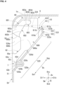
- the arm holder 6 is a member inserted into the holder accommodation portion 52 from a front side of the casing 1 and installed inside of the holder accommodation portion 52 so as to be detachable therefrom. As illustrated in FIGS. 1 and 4 , the arm holder 6 has a holding portion 60, a second engagement portion 61, and a fixed portion 62.
- the holding portion 60 has a main body portion 600 and an arm insertion portion 601 formed in the main body portion 600.
- the main body portion 600 is a member placed on the support surface 520d when being inserted into the holder accommodation portion 52, and the main body portion 600 corresponds to a main body part in the arm holder 6.
- an insertion direction Ds a direction in which the main body portion 600 is inserted into the holder accommodation portion 52
- the insertion direction Ds is a direction that matches with a direction in which the holder support portion 520 extends.
- One side, of both sides in the insertion direction Ds, in a direction away from the front surface 51 will be referred to as “a back side Dsb", and a side opposite thereto will be referred to as "a forward side Dsf".
- the main body portion 600 has a first holder surface 600a directed to the one side Dwr, a second holder surface 600b directed to the other side Dwl that is a side opposite to the first holder surface 600a, and a third holder surface 600c connecting the first holder surface 600a and the second holder surface 600b to each other and directed to the forward side Dsf.
- the second holder surface 600b faces the side wall surface 524a of the side wall portion 524 and comes into contact therewith.
- each of the elements (the arm insertion portion 601 of the holding portion 60, the second engagement portion 61, and the fixed portion 62) provided in the arm holder 6 when the holding portion 60 is inserted into the holder accommodation portion 52 and the main body portion 600 is placed on the support surface 520d will be described.
- the first guide surface 602a is a surface extending in a direction away from the front surface 51 and facing the support surface 520d of the holder support portion 520.
- the second guide surface 602b is a surface extending along the first guide surface 602a and facing the first guide surface 602a.
- the first abutment surface 602c is a surface connecting the first guide surface 602a and the second guide surface 602b to each other and directed to the one side Dwr on the other side Dwl of the first guide surface 602a and the second guide surface 602b.
- the bearing portion 603 is connected to the respective end edges of the first guide surface 602a, the second guide surface 602b, and the first abutment surface 602c on the back side Dsb from the backside Dib and holds the arm 8 guided by the guide portion 602.
- the bearing portion 603 has a bearing surface 603c, a first connection surface 603a, a second connection surface 603b, and a second abutment surface 603d.
- the bearing surface 603c is an inner circumferential surface of a half-cylinder recessed toward the backside Dib when viewed from the one side Dwr.
- the first connection surface 603a is a surface connecting the first guide surface 602a and the bearing surface 603c to each other and directed to the downside Dvd.
- the second connection surface 603b is a surface connecting the second guide surface 602b and the bearing surface 603c to each other and directed to the upside Dvu.
- the second abutment surface 603d is a surface connecting the first connection surface 603a, the second connection surface 603b, and the bearing surface 603c to each other and directed to the one side Dwr on the other side Dwl of the first guide surface 602a, the second guide surface 602b, and the bearing surface 603c.
- an inner surface of the arm insertion portion 601 serving as a groove is constituted of the first guide surface 602a, the second guide surface 602b, and the first abutment surface 602c of the guide portion 602, and the bearing surface 603c, the first connection surface 603a, the second connection surface 603b, and the second abutment surface 603d of the bearing portion 603.
- the bearing portion 603 according to the present embodiment is positioned on the upside Dvu of the opening 50a of the holder accommodation portion 52.
- the second engagement portion 61 is a member integrally formed on the main body portion 600 of the holding portion 60 so as to be protruded therefrom toward the back side Dsb from the main body portion 600 of the holding portion 60 and able to be interlocked with the first engagement portion 521.
- the second engagement portion 61 has a second base portion 610 and a second claw portion 611.
- the second base portion 610 is a member having a flat plate shape extending toward the back side Dsb from the main body portion 600.
- the second base portion 610 has a facing surface 610a facing the support surface 520d.
- the facing surface 610a spreads parallel to the spreading direction of the support surface 520d.
- the second claw portion 611 is a member having a flat plate shape extending to the backside Dib as it goes toward the downside Dvd from the end edge of the second base portion 610 on the back side Dsb.
- the second claw portion 611 according to the present embodiment has a reception surface 611b spreading in a direction perpendicular to a spreading direction of the facing surface 610a and connected to the facing surface 610a, and a second surface 611a directed to a side opposite to the reception surface 611b.
- the reception surface 611b and the second surface 611a of the second claw portion 611 spread parallel to spreading directions of the first surface 523a and the restraint surface 523b of the first claw portion 523 in the first engagement portion 521.
- the reception surface 611b and the second surface 611a of the second claw portion 611 are disposed at positions overlapping the first surface 523a and the restraint surface 523b when viewed in the insertion direction Ds.
- the first surface 523a of the first claw portion 523 receives a pressure from the second surface 611a of the second claw portion 611.
- the first engagement portion 521 since the first engagement portion 521 has flexibility, the first claw portion 523 and the first base portion 522 connected to the first claw portion 523 are bent toward the back side Dsb.
- the second surface 611a of the second claw portion 611 can go over the end edge on the first surface 523a of the first claw portion 523 and moves to the back side Dsb beyond the restraint surface 523b of the first claw portion 523. That is, the second claw portion 611 goes over the first claw portion 523 from the forward side Dsf toward the back side Dsb.
- first engagement portion 521 Since the first engagement portion 521 has flexibility, at the same time as the second claw portion 611 goes over the first claw portion 523, bending of the first claw portion 523 and the first base portion 522 toward the back side Dsb is released, and the first claw portion 523 and the first base portion 522 return to original positions.
- the restraint surface 523b of the first claw portion 523 and the reception surface 611b of the second claw portion 611 face each other in the insertion direction Ds and come into contact with each other.
- the main body portion 600 stands still on the support surface 520d. Through a series of the foregoing operation, engagement between the first engagement portion 521 and the second engagement portion 61 is completed.
- the fixed portion 62 is a member integrally formed on the main body portion 600 and fixed to the holder support portion 520.
- the fixed portion 62 itself is fixed to the holder support portion 520 so that the main body portion 600 is subjected to positioning on the support surface 520d.
- the fixed portion 62 has a fixed surface 62a extending from the main body portion 600 toward the forward side Dsf and being flush with the front surface 51 on the inner side of the opening 50a.
- a recessed groove 62b opening on the fixed surface 62a and recessed toward the backside Dib from this fixed surface 62a is formed in the fixed portion 62.
- a fixed portion fastening hole 62d opening on a groove bottom surface 62c of this recessed groove 62b and penetrating the fixed portion 62 toward the backside Dib from this groove bottom surface 62c is formed in the fixed portion 62.
- the fixed portion fastening hole 62d has a screw thread allowing the bolt 7 to be fastened thereto.
- the fixed portion 62 is subjected to spot-facing treatment such that a head portion of the bolt 7 does not protrude to the foreside Dif beyond the fixed surface 62a.
- This fixed portion fastening hole 62d provided in the fixed portion 62 is formed to have the same measurement as the fastening hole 520e provided in the holder support portion 520, is disposed from the foreside Dif with respect to this fastening hole 520e, and overlaps the fastening hole 520e in a manner of being connected thereto in the installation direction Di.
- the fixed portion 62 Due to the bolt 7 fastened to the fixed portion fastening hole 62d and the fastening hole 520e connected to each other from the foreside Dif, the fixed portion 62 is fixed to the holder support portion 520. That is, the bolt 7 is attached to the holder support portion 520 from the foreside Dif so that the fixed portion 62 is fixed to the holder support portion 520. In other words, since the bolt 7 is attached to the casing 1 from the foreside Dif, the arm holder 6 is fixed to the casing 1.
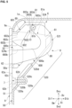
- the arm 8 is inserted into the holder accommodation portion 52 from the front side of the casing 1, and one end thereof is held by the arm holder 6 so that the arm 8 is allowed to turn around an axis O extending in the width direction Dw which is a longitudinal direction of the casing 1. As illustrated in FIGS. 1 and 5 , the arm 8 has a shaft portion 81 and an arm main body 80.
- the shaft portion 81 is a member having a columnar shape extending in the width direction Dw and having an outer circumferential surface 81a and a pair of end surfaces 81b.
- the shaft portion 81 extends in the width direction Dw in a state in which the arm 8 is inserted into the holder accommodation portion 52. That is, the end surface 81b, of the pair of end surfaces 81b arranged in the width direction Dw, on the one side Dwr is directed to the one side Dwr, and the end surface 81b, of the pair of end surfaces 81b, on the other side Dwl is directed to the other side Dwl.
- the shaft portion 81 is inserted into the holder accommodation portion 52 in a state of extending in the width direction Dw and then is inserted into the arm insertion portion 601 of the holding portion 60 in the arm holder 6.
- an insertion portion 82 a part bisecting the shaft portion 81 in the width direction Dw and positioned on the other side Dwl
- a non-insertion portion 83 a part positioned on the one side Dwr
- the shaft portion 81 in its entirety guided to the backward side Dsb by the guide portion 602 is guided to the following bearing surface 603c positioned on the backside Dib of the first connection surface 603a and the second connection surface 603b by the first connection surface 603a and the second connection surface 603b of the bearing portion 603.
- the shaft portion 81 in its entirety is held by this bearing surface 603c in a manner of being able to turn around the axis O.
- the arm main body 80 is a member connected to the shaft portion 81 and turning about the axis O in response to turning of the shaft portion 81. Specifically, one end of the arm main body 80 is fixed to the non-insertion portion 83 in the shaft portion 81. That is, the arm main body 80 integrally turns around the axis O with the shaft portion 81.
- the inlet panel 9 is a panel capable of shifting between a state of covering the front surface 51 of the front panel 50 from the foreside Dif and a state of not covering the front surface 51 in response to turning of the arms 8 around the axis O.
- the inlet panel 9 is connected to the other end of each of the arm main bodies 80.
- the end edge of the inlet panel 9 on the upside Dvu becomes a top edge 9a.
- the top edge 9a of the inlet panel 9 is positioned below the top edge 1a of the casing 1 when the inlet panel 9 is positioned at the closed position.
- the casing 1 opens on the front surface 51, and the holder accommodation portions 52 recessed toward the upside Dvu as they go toward the backside Dib are provided. Further, the arm holders 6 respectively inserted into the holder accommodation portions 52 are fixed to the insides of the holder accommodation portions 52 in an attachable/detachable manner.
- the arms 8 turnably held by the arm holders 6 turn in a manner of being able to move between the closed position where the front surface 51 is covered such that the inlet panel 9 covers the openings 50a of the holder accommodation portions 52 and the open position where the inlet panel 9 has moved forward and upward from the closed position and the front surface 51 has opened.
- the arms 8 extending from the arm holders 6 to the inlet panel 9 can be positioned farther to the downside Dvd. That is, the openings 50a of the holder accommodation portions 52 can be positioned farther to the downside Dvd.
- the inlet panel 9 when the inlet panel 9 is positioned at the closed position where the front surface 51 side is covered, the inlet panel 9 can completely cover the openings 50a of the holder accommodation portions 52 from the front side. Namely, a good appearance when the inlet panel 9 is closed is not impaired.
- the arm holders 6 are attached and detached inside the holder accommodation portions 52, the arms 8 held by these arm holders 6 and the inlet panel 9 fixed to these arms 8 can be attached and detached with respect to the casing 1 at the same time. Therefore, the arms 8 are easily attached and detached with respect to the casing 1.
- the indoor unit 100 of the embodiment when the inlet panel 9 is positioned at the closed position, the top edge 9a of the inlet panel 9 is positioned below the top edge 1a of the casing 1.
- the inlet panel 9 can be made compact and reduced in weight.
- the arm holders 6 can be fixed to the casing 1 using simple members such as bolts 7. Therefore, it is possible to curb increase in costs and man ⁇ hour related to manufacturing of the indoor unit 100.
- the indoor unit 100 of the embodiment in a condition where the holding portions 60 of the arm holders 6 are inserted into the holder accommodation portions 52, the second engagement portions 61 of the holder accommodation portions 52 are engaged with the first engagement portions 521 of the arm holders 6. Accordingly, since the holding portions 60 stand still on the support surfaces 520d, work of fixing the fixed portions 62 to the holder support portions 520 using the bolts 7 becomes easy.
- the holding portions 60 in the arm holders 6 respectively have the guide portions 602 guiding the shaft portions 81 of the arms 8 which have been inserted into the holder accommodation portions 52 to the bearing portions 603. Therefore, the arms 8 fixed to the insides of the holder accommodation portions 52 can be simply attached to the arm holders 6.
- the bearing portions 603 are positioned on the upside Dvu of the openings 50a of the holder accommodation portions 52. That is, the shaft portions 81 of the arms 8 can be rotatably held by the arm holders 6 on the upside Dvu of the openings 50a. Accordingly, a structure which is difficult to be directly formed in the casing 1 can be realized by the arm holders 6.
- first engagement portion 521 is formed of a material having flexibility
- first engagement portion 521 may not be formed of a material having flexibility
- second engagement portion 61 in place of the first engagement portion 521, may be formed of a material having flexibility
- both the first engagement portion 521 and the second engagement portion 61 may be formed of a material having flexibility.
Landscapes
- Engineering & Computer Science (AREA)
- Chemical & Material Sciences (AREA)
- Combustion & Propulsion (AREA)
- Mechanical Engineering (AREA)
- General Engineering & Computer Science (AREA)
- Air Filters, Heat-Exchange Apparatuses, And Housings Of Air-Conditioning Units (AREA)
- Compression-Type Refrigeration Machines With Reversible Cycles (AREA)
Claims (4)
- Inneneinheit (100), umfassend:ein Gehäuse (1), das eine vordere Fläche und Halteraufnahmeabschnitten (52) aufweist, die sich an der Vorderseite öffnen und zurückversetzt sind, um sich nach oben in Richtung einer Rückseite des Gehäuses zu neigen;Armhalter (6), die von einer Vorderseite des Gehäuses in die Halteraufnahmeabschnitte eingeführt werden und die innerhalb der Halteraufnahmeabschnitte installiert sind, um davon abnehmbar zu sein;Arme (8), die von der Vorderseite des Gehäuses in die Halteraufnahmeabschnitte eingesetzt werden und wovon jeweils ein erstes Ende von dem Armhalter gehalten wird, sodass es dem Arm ermöglicht ist, um eine Achse zu drehen, die sich in Längsrichtung des Gehäuses erstreckt; undeine Einlassplatte (9), an der ein zweites Ende von jedem der Arme befestigt ist,wobei der Bewegungsbereich der Arme um die Achse zwischen einer geschlossenen Position, in der die Einlassplatte auf eine Weise angeordnet ist, dass sie die vordere Fläche des Gehäuses überlappt und die Öffnungen der Halteraufnahmeabschnitte durch die Einlassplatte verschlossen sind, und einer offenen Position, in der die Einlassplatte vor und nach oben von der vorderen Fläche des Gehäuses angeordnet ist und die vordere Fläche des Gehäuses freiliegt, eingestellt ist,dadurch gekennzeichnet, dass die Inneneinheit (100) ferner Bolzen (7) umfasst, die jeweils von der Vorderseite des Gehäuses (1) daran befestigt sind, um den Armhalter (6) an dem Gehäuse zu befestigen,wobei die Halteraufnahmeabschnitte (52) jeweils Folgendes beinhalten:einen Halterstützabschnitt (520), der eine Stützfläche aufweist, die den Armhalter (6) von darunter stützt; undeinen ersten Eingriffsabschnitt (521), der flexibel ist und sich von der Stützfläche in einer die Stützfläche schneidenden Richtung nach oben erstreckt, undwobei die Armhalter jeweils Folgendes beinhalten:einen Halteabschnitt (60), der auf der Stützfläche platziert ist und den Arm (8) hält, um zu ermöglichen, dass er um die Achse gedreht wird;einen zweiten Eingriffsabschnitt (61), der einstückig an dem Halteabschnitt gebildet ist, um davon hervorzustehen, und der mit dem ersten Eingriffsabschnitt in einem Zustand in Eingriff ist, in dem der Halteabschnitt in den Halteraufnahmeabschnitt eingesetzt ist; undeinen feststehenden Abschnitt (62), der einstückig an den Halteabschnitt gebildet ist, um davon hervorzustehen, und der durch Befestigen des Bolzens (7) an dem Gehäuse (1) an dem Halterstützabschnitt installiert ist.
- Inneneinheit (100) nach Anspruch 1,
wobei eine Oberkante der Einlassplatte (9) unterhalb einer Kopfstufe des Gehäuses (1) in einem Zustand positioniert ist, in dem die Einlassplatte in der geschlossenen Position positioniert ist. - Inneneinheit (100) nach Anspruch 1 oder 2,
wobei die Arme (8) jeweils Folgendes beinhalten:einen Armhauptkörper (80), an dem die Einlassplatte (9) befestigt ist; undeinen Schaftabschnitt (81), der an dem Armhauptkörper gebildet ist, um die Achse auf einen Mittelpunkt des Schaftabschnitts einzustellen, und der es ermöglicht, den Armhauptkörper um die Achse zu drehen,wobei die Halteabschnitte (60) jeweils Folgendes beinhalten:einen Hauptkörperabschnitt (600); undeinen Armeinsetzabschnitt (601), der in dem Hauptkörperabschnitt gebildet ist, undwobei die Armeinsetzabschnitte jeweils Folgendes beinhalten:einen Führungsabschnitt (602), der gebildet ist, um den Schaftabschnitt in einer Richtung weg von der vorderen Fläche zu führen, während der Arm in den Halteraufnahmeabschnitt (52) eingesetzt wird; undeinen Lagerungsabschnitt (603), der den durch den Führungsabschnitt geführten Wellenabschnitt an dem Lagerungsabschnitt hält, um zu ermöglichen, dass der Armhauptkörper um die Achse gedreht wird. - Inneneinheit (100) nach Anspruch 3,
wobei der Lagerungsabschnitt (603) oberhalb der Öffnung des Halteraufnahmeabschnitts (52) positioniert ist.
Applications Claiming Priority (1)
| Application Number | Priority Date | Filing Date | Title |
|---|---|---|---|
| JP2021187983A JP7738464B2 (ja) | 2021-11-18 | 2021-11-18 | 室内機 |
Publications (3)
| Publication Number | Publication Date |
|---|---|
| EP4184065A1 EP4184065A1 (de) | 2023-05-24 |
| EP4184065C0 EP4184065C0 (de) | 2025-03-12 |
| EP4184065B1 true EP4184065B1 (de) | 2025-03-12 |
Family
ID=84357995
Family Applications (1)
| Application Number | Title | Priority Date | Filing Date |
|---|---|---|---|
| EP22207446.0A Active EP4184065B1 (de) | 2021-11-18 | 2022-11-15 | Innenraumeinheit |
Country Status (4)
| Country | Link |
|---|---|
| EP (1) | EP4184065B1 (de) |
| JP (1) | JP7738464B2 (de) |
| AU (1) | AU2022271410B2 (de) |
| ES (1) | ES3022133T3 (de) |
Family Cites Families (12)
| Publication number | Priority date | Publication date | Assignee | Title |
|---|---|---|---|---|
| JPH05133541A (ja) * | 1991-11-14 | 1993-05-28 | Sanyo Electric Co Ltd | 空気調和機 |
| JP3058001B2 (ja) | 1994-03-25 | 2000-07-04 | ダイキン工業株式会社 | パネルの取付構造 |
| JPH0945063A (ja) * | 1995-07-25 | 1997-02-14 | Hitachi Ltd | ビデオカセットレコーダの前面パネル |
| KR20030038954A (ko) * | 2001-11-09 | 2003-05-17 | 주식회사 엘지이아이 | 공기조화기의 흡입그릴 착탈 구조 |
| JP4265467B2 (ja) | 2004-04-15 | 2009-05-20 | パナソニック株式会社 | 換気扇 |
| JP2009097745A (ja) | 2007-10-15 | 2009-05-07 | Panasonic Corp | 分離型空気調和機の開閉装置 |
| JP2011064353A (ja) | 2009-09-15 | 2011-03-31 | Sharp Corp | 空気調和機 |
| JP5758834B2 (ja) | 2012-04-04 | 2015-08-05 | 三菱電機株式会社 | 空気調和機の室内機 |
| JP5968238B2 (ja) * | 2013-01-29 | 2016-08-10 | 三菱電機株式会社 | 空気調和機の床置き形室内機 |
| CN206847028U (zh) | 2016-01-18 | 2018-01-05 | 三菱电机株式会社 | 空调机的室内机 |
| CN207936329U (zh) | 2018-03-12 | 2018-10-02 | 广东美的制冷设备有限公司 | 空调室内机和空调器 |
| CN111503729B (zh) * | 2019-01-31 | 2022-01-28 | Lg电子株式会社 | 空气调节器的室内机及其控制方法 |
-
2021
- 2021-11-18 JP JP2021187983A patent/JP7738464B2/ja active Active
-
2022
- 2022-11-15 EP EP22207446.0A patent/EP4184065B1/de active Active
- 2022-11-15 ES ES22207446T patent/ES3022133T3/es active Active
- 2022-11-16 AU AU2022271410A patent/AU2022271410B2/en active Active
Also Published As
| Publication number | Publication date |
|---|---|
| EP4184065C0 (de) | 2025-03-12 |
| ES3022133T3 (en) | 2025-05-28 |
| EP4184065A1 (de) | 2023-05-24 |
| AU2022271410B2 (en) | 2024-02-01 |
| JP2023074839A (ja) | 2023-05-30 |
| AU2022271410A1 (en) | 2023-06-01 |
| JP7738464B2 (ja) | 2025-09-12 |
Similar Documents
| Publication | Publication Date | Title |
|---|---|---|
| EP1522795B1 (de) | Innenraumeinheit einer Klimaanlage | |
| US7275389B2 (en) | Indoor unit in air conditioner | |
| AU2004284342B2 (en) | Indoor unit in air conditioner | |
| EP2031316B1 (de) | Klimaanlage | |
| US7249466B2 (en) | Indoor unit in air conditioner | |
| EP1607690A1 (de) | Klimaanlage | |
| EP1580491B1 (de) | Innenraumeinheit einer Klimaanlage | |
| EP1533578A2 (de) | Innenraumeinheit einer Klimaanlage | |
| EP4184065A1 (de) | Innenraumeinheit | |
| JP3223164B2 (ja) | エンジンの冷却部構造 | |
| EP4187164B1 (de) | Innenraumeinheit | |
| EP3182029A1 (de) | Aussenlufteinheit für mehrfaches klimaanlagensystem | |
| EP1816403B1 (de) | Innenraumeinheit einer Klimaanlage | |
| ZA200603649B (en) | Indoor unit in air conditioner | |
| ZA200603706B (en) | Indoor unit in air conditioner | |
| KR20230111760A (ko) | 에어컨 | |
| ZA200603641B (en) | Indoor unit in air conditioner |
Legal Events
| Date | Code | Title | Description |
|---|---|---|---|
| PUAI | Public reference made under article 153(3) epc to a published international application that has entered the european phase |
Free format text: ORIGINAL CODE: 0009012 |
|
| STAA | Information on the status of an ep patent application or granted ep patent |
Free format text: STATUS: THE APPLICATION HAS BEEN PUBLISHED |
|
| AK | Designated contracting states |
Kind code of ref document: A1 Designated state(s): AL AT BE BG CH CY CZ DE DK EE ES FI FR GB GR HR HU IE IS IT LI LT LU LV MC ME MK MT NL NO PL PT RO RS SE SI SK SM TR |
|
| STAA | Information on the status of an ep patent application or granted ep patent |
Free format text: STATUS: REQUEST FOR EXAMINATION WAS MADE |
|
| 17P | Request for examination filed |
Effective date: 20231009 |
|
| RBV | Designated contracting states (corrected) |
Designated state(s): AL AT BE BG CH CY CZ DE DK EE ES FI FR GB GR HR HU IE IS IT LI LT LU LV MC ME MK MT NL NO PL PT RO RS SE SI SK SM TR |
|
| GRAP | Despatch of communication of intention to grant a patent |
Free format text: ORIGINAL CODE: EPIDOSNIGR1 |
|
| STAA | Information on the status of an ep patent application or granted ep patent |
Free format text: STATUS: GRANT OF PATENT IS INTENDED |
|
| INTG | Intention to grant announced |
Effective date: 20241121 |
|
| GRAS | Grant fee paid |
Free format text: ORIGINAL CODE: EPIDOSNIGR3 |
|
| GRAA | (expected) grant |
Free format text: ORIGINAL CODE: 0009210 |
|
| STAA | Information on the status of an ep patent application or granted ep patent |
Free format text: STATUS: THE PATENT HAS BEEN GRANTED |
|
| AK | Designated contracting states |
Kind code of ref document: B1 Designated state(s): AL AT BE BG CH CY CZ DE DK EE ES FI FR GB GR HR HU IE IS IT LI LT LU LV MC ME MK MT NL NO PL PT RO RS SE SI SK SM TR |
|
| REG | Reference to a national code |
Ref country code: GB Ref legal event code: FG4D |
|
| REG | Reference to a national code |
Ref country code: CH Ref legal event code: EP |
|
| REG | Reference to a national code |
Ref country code: DE Ref legal event code: R096 Ref document number: 602022011679 Country of ref document: DE |
|
| REG | Reference to a national code |
Ref country code: IE Ref legal event code: FG4D |
|
| U01 | Request for unitary effect filed |
Effective date: 20250318 |
|
| U07 | Unitary effect registered |
Designated state(s): AT BE BG DE DK EE FI FR IT LT LU LV MT NL PT RO SE SI Effective date: 20250324 |
|
| REG | Reference to a national code |
Ref country code: ES Ref legal event code: FG2A Ref document number: 3022133 Country of ref document: ES Kind code of ref document: T3 Effective date: 20250528 |
|
| PG25 | Lapsed in a contracting state [announced via postgrant information from national office to epo] |
Ref country code: RS Free format text: LAPSE BECAUSE OF FAILURE TO SUBMIT A TRANSLATION OF THE DESCRIPTION OR TO PAY THE FEE WITHIN THE PRESCRIBED TIME-LIMIT Effective date: 20250612 |
|
| PG25 | Lapsed in a contracting state [announced via postgrant information from national office to epo] |
Ref country code: NO Free format text: LAPSE BECAUSE OF FAILURE TO SUBMIT A TRANSLATION OF THE DESCRIPTION OR TO PAY THE FEE WITHIN THE PRESCRIBED TIME-LIMIT Effective date: 20250612 |
|
| PG25 | Lapsed in a contracting state [announced via postgrant information from national office to epo] |
Ref country code: HR Free format text: LAPSE BECAUSE OF FAILURE TO SUBMIT A TRANSLATION OF THE DESCRIPTION OR TO PAY THE FEE WITHIN THE PRESCRIBED TIME-LIMIT Effective date: 20250312 |
|
| PG25 | Lapsed in a contracting state [announced via postgrant information from national office to epo] |
Ref country code: GR Free format text: LAPSE BECAUSE OF FAILURE TO SUBMIT A TRANSLATION OF THE DESCRIPTION OR TO PAY THE FEE WITHIN THE PRESCRIBED TIME-LIMIT Effective date: 20250613 |
|
| PG25 | Lapsed in a contracting state [announced via postgrant information from national office to epo] |
Ref country code: SM Free format text: LAPSE BECAUSE OF FAILURE TO SUBMIT A TRANSLATION OF THE DESCRIPTION OR TO PAY THE FEE WITHIN THE PRESCRIBED TIME-LIMIT Effective date: 20250312 |
|
| PG25 | Lapsed in a contracting state [announced via postgrant information from national office to epo] |
Ref country code: PL Free format text: LAPSE BECAUSE OF FAILURE TO SUBMIT A TRANSLATION OF THE DESCRIPTION OR TO PAY THE FEE WITHIN THE PRESCRIBED TIME-LIMIT Effective date: 20250312 |
|
| PG25 | Lapsed in a contracting state [announced via postgrant information from national office to epo] |
Ref country code: CZ Free format text: LAPSE BECAUSE OF FAILURE TO SUBMIT A TRANSLATION OF THE DESCRIPTION OR TO PAY THE FEE WITHIN THE PRESCRIBED TIME-LIMIT Effective date: 20250312 |
|
| PG25 | Lapsed in a contracting state [announced via postgrant information from national office to epo] |
Ref country code: SK Free format text: LAPSE BECAUSE OF FAILURE TO SUBMIT A TRANSLATION OF THE DESCRIPTION OR TO PAY THE FEE WITHIN THE PRESCRIBED TIME-LIMIT Effective date: 20250312 |
|
| PG25 | Lapsed in a contracting state [announced via postgrant information from national office to epo] |
Ref country code: IS Free format text: LAPSE BECAUSE OF FAILURE TO SUBMIT A TRANSLATION OF THE DESCRIPTION OR TO PAY THE FEE WITHIN THE PRESCRIBED TIME-LIMIT Effective date: 20250712 |
|
| U20 | Renewal fee for the european patent with unitary effect paid |
Year of fee payment: 4 Effective date: 20251008 |
|
| PLBE | No opposition filed within time limit |
Free format text: ORIGINAL CODE: 0009261 |
|
| STAA | Information on the status of an ep patent application or granted ep patent |
Free format text: STATUS: NO OPPOSITION FILED WITHIN TIME LIMIT |
|
| REG | Reference to a national code |
Ref country code: CH Ref legal event code: L10 Free format text: ST27 STATUS EVENT CODE: U-0-0-L10-L00 (AS PROVIDED BY THE NATIONAL OFFICE) Effective date: 20260121 |
|
| PGFP | Annual fee paid to national office [announced via postgrant information from national office to epo] |
Ref country code: ES Payment date: 20251209 Year of fee payment: 4 |
|
| 26N | No opposition filed |
Effective date: 20251215 |