EP4183639A1 - Apparatus for releasing a parking brake of a vehicle, notably a railway vehicle, and related vehicle - Google Patents
Apparatus for releasing a parking brake of a vehicle, notably a railway vehicle, and related vehicle Download PDFInfo
- Publication number
- EP4183639A1 EP4183639A1 EP22207984.0A EP22207984A EP4183639A1 EP 4183639 A1 EP4183639 A1 EP 4183639A1 EP 22207984 A EP22207984 A EP 22207984A EP 4183639 A1 EP4183639 A1 EP 4183639A1
- Authority
- EP
- European Patent Office
- Prior art keywords
- vehicle
- parking brake
- releasing
- actuating means
- electrical motor
- Prior art date
- Legal status (The legal status is an assumption and is not a legal conclusion. Google has not performed a legal analysis and makes no representation as to the accuracy of the status listed.)
- Granted
Links
Images

Classifications
-
- B—PERFORMING OPERATIONS; TRANSPORTING
- B60—VEHICLES IN GENERAL
- B60T—VEHICLE BRAKE CONTROL SYSTEMS OR PARTS THEREOF; BRAKE CONTROL SYSTEMS OR PARTS THEREOF, IN GENERAL; ARRANGEMENT OF BRAKING ELEMENTS ON VEHICLES IN GENERAL; PORTABLE DEVICES FOR PREVENTING UNWANTED MOVEMENT OF VEHICLES; VEHICLE MODIFICATIONS TO FACILITATE COOLING OF BRAKES
- B60T7/00—Brake-action initiating means
- B60T7/02—Brake-action initiating means for personal initiation
- B60T7/08—Brake-action initiating means for personal initiation hand actuated
- B60T7/10—Disposition of hand control
- B60T7/107—Disposition of hand control with electrical power assistance
-
- B—PERFORMING OPERATIONS; TRANSPORTING
- B60—VEHICLES IN GENERAL
- B60T—VEHICLE BRAKE CONTROL SYSTEMS OR PARTS THEREOF; BRAKE CONTROL SYSTEMS OR PARTS THEREOF, IN GENERAL; ARRANGEMENT OF BRAKING ELEMENTS ON VEHICLES IN GENERAL; PORTABLE DEVICES FOR PREVENTING UNWANTED MOVEMENT OF VEHICLES; VEHICLE MODIFICATIONS TO FACILITATE COOLING OF BRAKES
- B60T13/00—Transmitting braking action from initiating means to ultimate brake actuator with power assistance or drive; Brake systems incorporating such transmitting means, e.g. air-pressure brake systems
- B60T13/74—Transmitting braking action from initiating means to ultimate brake actuator with power assistance or drive; Brake systems incorporating such transmitting means, e.g. air-pressure brake systems with electrical assistance or drive
- B60T13/746—Transmitting braking action from initiating means to ultimate brake actuator with power assistance or drive; Brake systems incorporating such transmitting means, e.g. air-pressure brake systems with electrical assistance or drive and mechanical transmission of the braking action
-
- B—PERFORMING OPERATIONS; TRANSPORTING
- B61—RAILWAYS
- B61H—BRAKES OR OTHER RETARDING DEVICES SPECIALLY ADAPTED FOR RAIL VEHICLES; ARRANGEMENT OR DISPOSITION THEREOF IN RAIL VEHICLES
- B61H13/00—Actuating rail-vehicle brakes
- B61H13/02—Hand or other personal actuation
-
- F—MECHANICAL ENGINEERING; LIGHTING; HEATING; WEAPONS; BLASTING
- F16—ENGINEERING ELEMENTS AND UNITS; GENERAL MEASURES FOR PRODUCING AND MAINTAINING EFFECTIVE FUNCTIONING OF MACHINES OR INSTALLATIONS; THERMAL INSULATION IN GENERAL
- F16D—COUPLINGS FOR TRANSMITTING ROTATION; CLUTCHES; BRAKES
- F16D2127/00—Auxiliary mechanisms
- F16D2127/02—Release mechanisms
Definitions
- the present invention concerns an apparatus for releasing a parking brake of a vehicle, notably a railway vehicle, and a vehicle comprising such an apparatus.
- the present invention is particularly suitable for being used with railways vehicles, such as train or metro convoys, and will be described hereinafter by making reference to such application without intending in any way to limit its possible use with other suitable types of vehicles; further, the term vehicle has to be understood hereinafter as encompassing a vehicle formed by one or more parts or units, such as a train including one or more cars.
- Such parking brakes are associated with suitable mechanisms adapted to release the parking brake and allow the vehicle to move from the stationary position.
- the cable is operated by a handle which is pulled by an operator; in particular, the operator has first to get off from the vehicle and then to act manually directly on the handle.
- the operator can use a special tool to pull the handle standing from the door side on board of the vehicle.
- the main aim of the present invention is to provide a release apparatus capable of mitigating such issues and offering some improvements over known solutions, while allowing to adequately and efficiently release an associated parking brake.
- an apparatus for releasing a parking brake of a vehicle apparatus for releasing a parking brake of a vehicle comprising:
- a vehicle notably a railway vehicle, comprising at least one parking brake, wherein it further comprises at least one apparatus for releasing said parking brake as above indicated, and in particular as described hereinafter and defined in the appended relevant claims.
- any component as a whole, or to any part of a component, or to a combination of components, it has to be understood that it means and encompasses correspondingly either the structure, and/or configuration and/or form and/or positioning of the related component or part thereof, or combinations, such term refers to.
- transversal or transversally when used herein, it has to be understood as encompassing an actual variation of plus or minus 5% with respect to an indicated reference value, axis or position, and when the terms transversal or transversally are hereby used, they have to be understood as encompassing a direction non-parallel to the reference part(s) or direction(s)/axis they refer to, and perpendicularity has to be considered a specific case of transverse direction.
- Figure 1 shows an apparatus indicated by the cumulative reference number 100, and hereinafter referred to also as the release apparatus 100, which is suitable to release a parking brake of a vehicle on which the apparatus itself is installed.
- the release apparatus 100 comprises a release mechanism 1 which can be actuated to move between a locking position where it locks the parking brake into a braking operative position where the parking brake holds the vehicle in a substantially still position, and a releasing position where it releases the parking brake from holding the vehicle in said still position.
- the release mechanism 1 comprises for example a valve 2 having a valve pin 3 and a hinge mechanism 4.
- the hinge mechanism 4 pulls up the valve pin 3 thus causing the parking brake to be released.
- the release apparatus 100 further comprises a plurality of actuating means which are configured and mutually arranged to selectively actuate either automatically or manually the release mechanism 1 to move from the locking position into the releasing position.
- the plurality of actuating means comprises a device 20, a cable 10, in particular a flexible cable, which has one end 12 connected to the release mechanism 1, and in particular to the hinge mechanism 4, and a second opposite end 14 which is connected to the device 20 which is adapted to be actuated either manually or automatically to stretch the flexible cable 10 and thus cause the release mechanism 1, and in particular the valve pin 3, to move from the locking position into said releasing position.
- such device 20 comprises or is constituted by a spool (hereinafter referred to by the same reference number 20 for ease of illustration) having a body configured for wrapping around it at least a portion of the cable 10.
- the release apparatus 100 comprises an electrical motor 30 which is mounted on a frame 110 of the vehicle.
- the electrical motor 30 is a geared DC motor.
- the frame 110 can be any suitable part of the vehicle, e.g. a part of a boogie of a train car.
- the motor 30 is mechanically connected to the frame 110 by using a connecting plate 112 which is fixed to the frame 110, and a mounting bracket 114 connected to the connecting plate 112.
- the electrical motor 30 comprises a motor shaft 32 which is pivotally connected to the mounting bracket 114, for example via at least one bearing 116.
- the spool 20 is mounted on the motor shaft 32.
- the spool 20 is connected to the motor shaft 32 in such a way that it can rotate solidly with the shaft 32 when the motor 30 is functioning and therefore the release apparatus 100 is carrying out automatically, and in particularly electrically, the release of the parking brake, and to freely rotate relative to the motor 30 when the motor 30 is not fed and the release of the parking brake is under manual execution, as it will be described in more details hereinafter.
- the plurality of actuating means comprises a switch 40 which is adapted to start/stop the electrical motor 30.
- the switch 40 is conveniently installed on the vehicle in a position remote from the electrical motor 30, e.g. in a position, such as the cabin of the driver, where an operator when necessary can push it in order to start feeding the motor 30, and thus initiating the release of the parking break automatically.
- the feeding power for the motor 30 can be provided for example by a power system on board of the vehicle itself.
- the plurality of actuating means comprises also one or more rechargeable batteries 15 for electrically feeding the electrical motor 30.
- the one or more batteries can be installed on board of the vehicle and connected to the motor when needed.
- the plurality of actuating means further comprises a handle 25 which is configured to be connected to the spool 20, for example in a receiving seat 27, and to be actuated manually by an operator in order to wrap around it at least a portion of the cable 10.
- the electrical motor starts rotating and drags into rotation the spool 20 rotating solidly with the motor shaft 32.
- the cable 10 is wrapped around the spool 20 and thus is stretched pulling the hinge mechanism 4.
- the hinge mechanism 4 rotates and pulls up the valve pin 3, thus causing the parking brake to be released.
- the parking brake has to be released manually, an operator can disengage the coupling between the spool 20 and the motor 30; then the handle 25 can be inserted into the seat 27, and the operator, by acting on the handle 25 can rotate the spool 20 that rotates together with the motor shaft 32 relative to the motor 30.
- the cable 10 is wrapped around the spool 20 and, similarly to the automatic release, the hinge mechanism 4 is caused to rotate by the pulling force of the cable 10 and pulls up the valve pin 3 which eventually releases the parking brake.
- the release apparatus 100 and related vehicle according to the present invention allow achieving the intended aim since the release of the parking brake can be carried automatically by using the electrically operated motor 30, thus in a faster way with respect to known solutions and without requiring any physical efforts to operators; further, the release apparatus 100 can be used also manually if desired or needed, according to a solution which in any case is simple to be used, and that requires less efforts and less execution time compared with known solutions.
- the release apparatus 100 and related vehicle thus conceived are susceptible of modifications and variations, all of which are within the scope of the inventive concept as defined in particular by the appended claims; for example, some of the components can be differently shaped or differently positioned provided that they remain compatible with the scope and functionalities there are devised for within the frame of the present invention.
Landscapes
- Engineering & Computer Science (AREA)
- Mechanical Engineering (AREA)
- Transportation (AREA)
- Regulating Braking Force (AREA)
- Braking Elements And Transmission Devices (AREA)
Abstract
Description
- The present invention concerns an apparatus for releasing a parking brake of a vehicle, notably a railway vehicle, and a vehicle comprising such an apparatus.
- The present invention is particularly suitable for being used with railways vehicles, such as train or metro convoys, and will be described hereinafter by making reference to such application without intending in any way to limit its possible use with other suitable types of vehicles; further, the term vehicle has to be understood hereinafter as encompassing a vehicle formed by one or more parts or units, such as a train including one or more cars.
- The use of parking brakes for temporarily holding for example railway vehicles immobilized in a parked position, is well known.
- Such parking brakes are associated with suitable mechanisms adapted to release the parking brake and allow the vehicle to move from the stationary position.
- At present, although known release mechanisms perform properly their functional tasks, they still present some aspects susceptible of further improvements.
- For instance, one solution currently adopted foresees the use of a cable which is manually operated in order to pull a valve and release the parking brake.
- To this end, the cable is operated by a handle which is pulled by an operator; in particular, the operator has first to get off from the vehicle and then to act manually directly on the handle.
- Alternatively, the operator can use a special tool to pull the handle standing from the door side on board of the vehicle.
- In both cases, this kind of release solution is substantially inconvenient, it demands substantial physical efforts to operators, and is highly time consuming in particular when the vehicle is a large one, e.g. in case of a train with many cars.
- The main aim of the present invention is to provide a release apparatus capable of mitigating such issues and offering some improvements over known solutions, while allowing to adequately and efficiently release an associated parking brake.
- This aim is achieved by an apparatus for releasing a parking brake of a vehicle apparatus for releasing a parking brake of a vehicle, comprising:
- a release mechanism which can be actuated to move between a locking position where it locks the parking brake into a braking operative position where the parking brake holds the vehicle in a substantially still parked position, and a releasing position where it releases the parking brake from holding the vehicle in said parked position; wherein the apparatus further comprises a plurality of actuating means which are configured and mutually arranged to selectively actuate either automatically or manually the release mechanism to move from the locking position into said releasing position.
- This aim is also achieved by a vehicle, notably a railway vehicle, comprising at least one parking brake, wherein it further comprises at least one apparatus for releasing said parking brake as above indicated, and in particular as described hereinafter and defined in the appended relevant claims.
- Further characteristics and advantages will become apparent from the description of some preferred but not exclusive exemplary embodiments of a release apparatus according to the present disclosure, illustrated only by way of non-limitative examples with the accompanying drawings, wherein:
-
Figure 1 is a perspective view schematically showing the release apparatus according to the invention; -
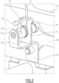
Figure 2 shows in more details some of the components of the release apparatus according to the invention, which are illustrated within the circled area "A" infigure 1 ; -
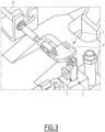
Figure 3 is a perspective view showing in more details the release mechanism of the release apparatus according to the invention, which are illustrated within the circled area "B" infigure 1 . - It should be noted that in the detailed description that follows, identical or similar components, either from a structural and/or functional point of view, may have the same or different reference numerals, regardless of whether they are shown in different embodiments of figures of the present disclosure; it should also be noted that in order to clearly and concisely describe the present disclosure, the drawings may not necessarily be to scale and certain features of the disclosure may be shown in somewhat schematic form.
- Further, when the term "adapted" or "arranged" or "configured" or "shaped", or "set" or any similar term is used herein while referring to any component as a whole, or to any part of a component, or to a combination of components, it has to be understood that it means and encompasses correspondingly either the structure, and/or configuration and/or form and/or positioning of the related component or part thereof, or combinations, such term refers to.
- In addition, when the term "about" or "substantial" or "substantially" is used herein, it has to be understood as encompassing an actual variation of plus or minus 5% with respect to an indicated reference value, axis or position, and when the terms transversal or transversally are hereby used, they have to be understood as encompassing a direction non-parallel to the reference part(s) or direction(s)/axis they refer to, and perpendicularity has to be considered a specific case of transverse direction.
-
Figure 1 shows an apparatus indicated by thecumulative reference number 100, and hereinafter referred to also as therelease apparatus 100, which is suitable to release a parking brake of a vehicle on which the apparatus itself is installed. - The
release apparatus 100 according to the invention comprises a release mechanism 1 which can be actuated to move between a locking position where it locks the parking brake into a braking operative position where the parking brake holds the vehicle in a substantially still position, and a releasing position where it releases the parking brake from holding the vehicle in said still position. - In the exemplary embodiment illustrated in
figures 1 and3 , the release mechanism 1 comprises for example avalve 2 having avalve pin 3 and ahinge mechanism 4. - As it will be described in more details hereinafter, when actuated to rotate, the
hinge mechanism 4 pulls up thevalve pin 3 thus causing the parking brake to be released. - Advantageously, the
release apparatus 100 according to the invention further comprises a plurality of actuating means which are configured and mutually arranged to selectively actuate either automatically or manually the release mechanism 1 to move from the locking position into the releasing position. - The term "automatically" has to be understood hereby as referring to an actuation that is executed without using a manual force or without requiring an intervention of a human operator, apart from the initial command needed to be imparted in order to start the release operation.
- According to a possible embodiment, the plurality of actuating means comprises a
device 20, acable 10, in particular a flexible cable, which has oneend 12 connected to the release mechanism 1, and in particular to thehinge mechanism 4, and a secondopposite end 14 which is connected to thedevice 20 which is adapted to be actuated either manually or automatically to stretch theflexible cable 10 and thus cause the release mechanism 1, and in particular thevalve pin 3, to move from the locking position into said releasing position. - Conveniently, according to a possible embodiment of the
release apparatus 100 according to the invention, as illustrated infigures 2 and3 ,such device 20 comprises or is constituted by a spool (hereinafter referred to by thesame reference number 20 for ease of illustration) having a body configured for wrapping around it at least a portion of thecable 10. - Further, as illustrated in
figures 2 and3 therelease apparatus 100 comprises anelectrical motor 30 which is mounted on aframe 110 of the vehicle. - According to a possible embodiment, the
electrical motor 30 is a geared DC motor. - The
frame 110 can be any suitable part of the vehicle, e.g. a part of a boogie of a train car. - As illustrated in more details in
figure 2 , themotor 30 is mechanically connected to theframe 110 by using a connectingplate 112 which is fixed to theframe 110, and amounting bracket 114 connected to the connectingplate 112. - According to the exemplary embodiment illustrated, the
electrical motor 30 comprises amotor shaft 32 which is pivotally connected to themounting bracket 114, for example via at least one bearing 116. - The
spool 20 is mounted on themotor shaft 32. - In particular, according to solutions readily available to those skilled in the art and therefore not described herein in details, the
spool 20 is connected to themotor shaft 32 in such a way that it can rotate solidly with theshaft 32 when themotor 30 is functioning and therefore therelease apparatus 100 is carrying out automatically, and in particularly electrically, the release of the parking brake, and to freely rotate relative to themotor 30 when themotor 30 is not fed and the release of the parking brake is under manual execution, as it will be described in more details hereinafter. - Further, as schematically illustrated in
figure 1 , the plurality of actuating means comprises aswitch 40 which is adapted to start/stop theelectrical motor 30. - In particular, the
switch 40 is conveniently installed on the vehicle in a position remote from theelectrical motor 30, e.g. in a position, such as the cabin of the driver, where an operator when necessary can push it in order to start feeding themotor 30, and thus initiating the release of the parking break automatically. - The feeding power for the
motor 30 can be provided for example by a power system on board of the vehicle itself. - According to a possible embodiment, the plurality of actuating means comprises also one or more
rechargeable batteries 15 for electrically feeding theelectrical motor 30. - The one or more batteries can be installed on board of the vehicle and connected to the motor when needed.
- Usefully, in the
release apparatus 100 according to the invention, the plurality of actuating means further comprises ahandle 25 which is configured to be connected to thespool 20, for example in a receivingseat 27, and to be actuated manually by an operator in order to wrap around it at least a portion of thecable 10. - In practice, when it is necessary to release the parking brake, an operator can push the
switch 40 thus triggering the onboard power system or the one or moreelectrical batteries 15 to feed theelectrical motor 30. - The electrical motor starts rotating and drags into rotation the
spool 20 rotating solidly with themotor shaft 32. During the rotation, thecable 10 is wrapped around thespool 20 and thus is stretched pulling thehinge mechanism 4. As a consequence thehinge mechanism 4 rotates and pulls up thevalve pin 3, thus causing the parking brake to be released. - If for whatever reason, e.g. due to lack of available electrical power, the parking brake has to be released manually, an operator can disengage the coupling between the
spool 20 and themotor 30; then thehandle 25 can be inserted into theseat 27, and the operator, by acting on thehandle 25 can rotate thespool 20 that rotates together with themotor shaft 32 relative to themotor 30. - In this way, the
cable 10 is wrapped around thespool 20 and, similarly to the automatic release, thehinge mechanism 4 is caused to rotate by the pulling force of thecable 10 and pulls up thevalve pin 3 which eventually releases the parking brake. - Hence, it is evident from the foregoing description that the
release apparatus 100 and related vehicle according to the present invention allow achieving the intended aim since the release of the parking brake can be carried automatically by using the electrically operatedmotor 30, thus in a faster way with respect to known solutions and without requiring any physical efforts to operators; further, therelease apparatus 100 can be used also manually if desired or needed, according to a solution which in any case is simple to be used, and that requires less efforts and less execution time compared with known solutions. - These results are achieved according to a solution which can be realized in a simpler way with respect to known solutions, and is very easy to be installed in principle in any suitable type of new or existing vehicles.
- The
release apparatus 100 and related vehicle thus conceived are susceptible of modifications and variations, all of which are within the scope of the inventive concept as defined in particular by the appended claims; for example, some of the components can be differently shaped or differently positioned provided that they remain compatible with the scope and functionalities there are devised for within the frame of the present invention. - All the details may furthermore be replaced with technically equivalent elements.
Claims (11)
- An apparatus (100) for releasing a parking brake of a vehicle, comprising:- a release mechanism (1) which can be actuated to move between a locking position where it locks the parking brake into a braking operative position where the parking brake holds the vehicle in a substantially still parked position, and a releasing position where it releases the parking brake from holding the vehicle in said parked position; wherein the apparatus (100) further comprises a plurality of actuating means which are configured and mutually arranged to selectively actuate either automatically or manually the release mechanism (1) to move from the locking position into said releasing position.
- The apparatus (100) as in claim 1, wherein the plurality of actuating means comprises at least a device (20), a flexible cable (10) having one end (12) connected to said release mechanism (1) and a second opposite end (14) connected to said device (20), and wherein said device (20) is adapted to be actuated manually or automatically to stretch the flexible cable (10) and cause the release mechanism (1) to move from the locking position into said releasing position.
- The apparatus (100) as in claim 2, wherein said device (20) is constituted or comprises a spool having a body configured for wrapping around it at least a portion of said flexible cable (10).
- The apparatus (100) as in any of the preceding claims, wherein the plurality of actuating means further comprises an electrical motor (30) mounted on a frame (110) of the vehicle.
- The apparatus (100) as in claims 3 and 4, wherein said electrical motor (30) comprises a motor shaft (32) and said spool is mounted on said rotor shaft (32).
- The apparatus (100) as in any of claims 4 to 5, wherein the plurality of actuating means further comprises a switch (40) adapted to start/stop said electrical motor (30).
- The apparatus (100) as in claim 6, wherein said switch (40) is mounted on the vehicle in a position remote from said electrical motor (30).
- The apparatus (100) as in any of the claims 4 to 6, wherein said electrical motor (30) is a geared DC motor.
- The apparatus (100) as in in any one of the claims 4 to 7, wherein the plurality of actuating means further comprises one or more rechargeable batteries (15) for electrically feeding said electrical motor (30).
- The apparatus (100) as in claim 3, wherein the plurality of actuating means further comprises a handle (25) which is configured to be connected to said spool and to be actuated manually by an operator to wrap around it at least a portion of said flexible cable (10).
- A vehicle comprising at least one parking brake, wherein it further comprises at least one apparatus (100) for releasing said parking brake as in any of the preceding claims.
Applications Claiming Priority (1)
| Application Number | Priority Date | Filing Date | Title |
|---|---|---|---|
| IN202141053310 | 2021-11-19 |
Publications (2)
| Publication Number | Publication Date |
|---|---|
| EP4183639A1 true EP4183639A1 (en) | 2023-05-24 |
| EP4183639B1 EP4183639B1 (en) | 2025-02-26 |
Family
ID=84359280
Family Applications (1)
| Application Number | Title | Priority Date | Filing Date |
|---|---|---|---|
| EP22207984.0A Active EP4183639B1 (en) | 2021-11-19 | 2022-11-17 | Apparatus for releasing a parking brake of a vehicle, notably a railway vehicle, and related vehicle |
Country Status (2)
| Country | Link |
|---|---|
| EP (1) | EP4183639B1 (en) |
| ES (1) | ES3020343T3 (en) |
Citations (6)
| Publication number | Priority date | Publication date | Assignee | Title |
|---|---|---|---|---|
| WO2002036408A2 (en) * | 2000-11-02 | 2002-05-10 | Graham-White Manufacturing Company | Locomotive parking brake |
| US20030070884A1 (en) * | 2000-02-11 | 2003-04-17 | Nui Wang | Electric brake actuator |
| US6913325B2 (en) * | 2003-02-05 | 2005-07-05 | Ellcon National, Inc. | Electrically operable vehicle parking brake drive |
| US20060016647A1 (en) * | 2003-09-09 | 2006-01-26 | Engle Thomas H | Automatic parking brake for a rail vehicle |
| EP1462330B1 (en) * | 2003-03-26 | 2007-06-27 | Dura Global Technologies, Inc. | Self adjusting electrically powered parking brake actuator mechanism with manual release |
| DE102007033007B4 (en) * | 2007-07-16 | 2019-05-23 | Robert Bosch Gmbh | Parking brake system for a vehicle |
-
2022
- 2022-11-17 ES ES22207984T patent/ES3020343T3/en active Active
- 2022-11-17 EP EP22207984.0A patent/EP4183639B1/en active Active
Patent Citations (6)
| Publication number | Priority date | Publication date | Assignee | Title |
|---|---|---|---|---|
| US20030070884A1 (en) * | 2000-02-11 | 2003-04-17 | Nui Wang | Electric brake actuator |
| WO2002036408A2 (en) * | 2000-11-02 | 2002-05-10 | Graham-White Manufacturing Company | Locomotive parking brake |
| US6913325B2 (en) * | 2003-02-05 | 2005-07-05 | Ellcon National, Inc. | Electrically operable vehicle parking brake drive |
| EP1462330B1 (en) * | 2003-03-26 | 2007-06-27 | Dura Global Technologies, Inc. | Self adjusting electrically powered parking brake actuator mechanism with manual release |
| US20060016647A1 (en) * | 2003-09-09 | 2006-01-26 | Engle Thomas H | Automatic parking brake for a rail vehicle |
| DE102007033007B4 (en) * | 2007-07-16 | 2019-05-23 | Robert Bosch Gmbh | Parking brake system for a vehicle |
Also Published As
| Publication number | Publication date |
|---|---|
| ES3020343T3 (en) | 2025-05-22 |
| EP4183639B1 (en) | 2025-02-26 |
Similar Documents
| Publication | Publication Date | Title |
|---|---|---|
| US3937295A (en) | Brake control apparatus for automatically engaging and disengaging the park brakes of a vehicle | |
| CN102395493B (en) | Method for operating a braking system, braking system and motor vehicle having braking system | |
| AU2020201936B2 (en) | Locomotive parking brake | |
| CN107054324B (en) | Parking brake assist device and vehicle | |
| US20190112845A1 (en) | Door handle arrangement of a motor vehicle | |
| KR101755699B1 (en) | Electronic parking brake system | |
| CN110306886B (en) | An in-vehicle emergency unlocking device for a passenger compartment door system | |
| EP4183639B1 (en) | Apparatus for releasing a parking brake of a vehicle, notably a railway vehicle, and related vehicle | |
| CN101296827A (en) | Braking System | |
| CN106985800B (en) | Braking device and road cleaning vehicle | |
| US20120024104A1 (en) | Parking brake drive unit | |
| KR102262170B1 (en) | Compulsory brake release device for railway vehicles | |
| KR101316380B1 (en) | Electronic Parking brake | |
| JPH0813543B2 (en) | Braking device for printing machine main drive motor | |
| KR100380612B1 (en) | Push button automatic parking system | |
| KR100198093B1 (en) | When the door is opened, | |
| KR100380933B1 (en) | Electricmotive Parking Brake Apparatus for Vehicle | |
| KR100387820B1 (en) | The electric driven tension adjuster of an automotive parking brake | |
| KR200167968Y1 (en) | A parking brake | |
| KR200229911Y1 (en) | Operation device of break machine for freight car | |
| CN201002594Y (en) | Automatic train stop | |
| KR100387871B1 (en) | The parking brake using a transmission gear shift | |
| JPS645223Y2 (en) | ||
| KR960001185Y1 (en) | The brake devices for rail vehicles | |
| KR19980043193A (en) | Unlocking device of parking brake lever |
Legal Events
| Date | Code | Title | Description |
|---|---|---|---|
| PUAI | Public reference made under article 153(3) epc to a published international application that has entered the european phase |
Free format text: ORIGINAL CODE: 0009012 |
|
| STAA | Information on the status of an ep patent application or granted ep patent |
Free format text: STATUS: THE APPLICATION HAS BEEN PUBLISHED |
|
| AK | Designated contracting states |
Kind code of ref document: A1 Designated state(s): AL AT BE BG CH CY CZ DE DK EE ES FI FR GB GR HR HU IE IS IT LI LT LU LV MC ME MK MT NL NO PL PT RO RS SE SI SK SM TR |
|
| STAA | Information on the status of an ep patent application or granted ep patent |
Free format text: STATUS: REQUEST FOR EXAMINATION WAS MADE |
|
| 17P | Request for examination filed |
Effective date: 20230531 |
|
| RBV | Designated contracting states (corrected) |
Designated state(s): AL AT BE BG CH CY CZ DE DK EE ES FI FR GB GR HR HU IE IS IT LI LT LU LV MC ME MK MT NL NO PL PT RO RS SE SI SK SM TR |
|
| P01 | Opt-out of the competence of the unified patent court (upc) registered |
Effective date: 20230822 |
|
| GRAP | Despatch of communication of intention to grant a patent |
Free format text: ORIGINAL CODE: EPIDOSNIGR1 |
|
| STAA | Information on the status of an ep patent application or granted ep patent |
Free format text: STATUS: GRANT OF PATENT IS INTENDED |
|
| RIC1 | Information provided on ipc code assigned before grant |
Ipc: F16D 127/02 20120101ALN20241002BHEP Ipc: B61H 13/02 20060101ALI20241002BHEP Ipc: B60T 13/74 20060101ALI20241002BHEP Ipc: B60T 7/10 20060101AFI20241002BHEP |
|
| INTG | Intention to grant announced |
Effective date: 20241104 |
|
| RIN1 | Information on inventor provided before grant (corrected) |
Inventor name: NARAYANA KURUP, SAJAN KUMAR |
|
| GRAS | Grant fee paid |
Free format text: ORIGINAL CODE: EPIDOSNIGR3 |
|
| GRAA | (expected) grant |
Free format text: ORIGINAL CODE: 0009210 |
|
| STAA | Information on the status of an ep patent application or granted ep patent |
Free format text: STATUS: THE PATENT HAS BEEN GRANTED |
|
| AK | Designated contracting states |
Kind code of ref document: B1 Designated state(s): AL AT BE BG CH CY CZ DE DK EE ES FI FR GB GR HR HU IE IS IT LI LT LU LV MC ME MK MT NL NO PL PT RO RS SE SI SK SM TR |
|
| REG | Reference to a national code |
Ref country code: GB Ref legal event code: FG4D |
|
| REG | Reference to a national code |
Ref country code: CH Ref legal event code: EP |
|
| REG | Reference to a national code |
Ref country code: DE Ref legal event code: R096 Ref document number: 602022011063 Country of ref document: DE |
|
| REG | Reference to a national code |
Ref country code: IE Ref legal event code: FG4D |
|
| REG | Reference to a national code |
Ref country code: ES Ref legal event code: FG2A Ref document number: 3020343 Country of ref document: ES Kind code of ref document: T3 Effective date: 20250522 |
|
| REG | Reference to a national code |
Ref country code: NL Ref legal event code: MP Effective date: 20250226 |
|
| PG25 | Lapsed in a contracting state [announced via postgrant information from national office to epo] |
Ref country code: RS Free format text: LAPSE BECAUSE OF FAILURE TO SUBMIT A TRANSLATION OF THE DESCRIPTION OR TO PAY THE FEE WITHIN THE PRESCRIBED TIME-LIMIT Effective date: 20250526 |
|
| PG25 | Lapsed in a contracting state [announced via postgrant information from national office to epo] |
Ref country code: FI Free format text: LAPSE BECAUSE OF FAILURE TO SUBMIT A TRANSLATION OF THE DESCRIPTION OR TO PAY THE FEE WITHIN THE PRESCRIBED TIME-LIMIT Effective date: 20250226 |
|
| PG25 | Lapsed in a contracting state [announced via postgrant information from national office to epo] |
Ref country code: PL Free format text: LAPSE BECAUSE OF FAILURE TO SUBMIT A TRANSLATION OF THE DESCRIPTION OR TO PAY THE FEE WITHIN THE PRESCRIBED TIME-LIMIT Effective date: 20250226 |
|
| REG | Reference to a national code |
Ref country code: LT Ref legal event code: MG9D |
|
| PG25 | Lapsed in a contracting state [announced via postgrant information from national office to epo] |
Ref country code: NO Free format text: LAPSE BECAUSE OF FAILURE TO SUBMIT A TRANSLATION OF THE DESCRIPTION OR TO PAY THE FEE WITHIN THE PRESCRIBED TIME-LIMIT Effective date: 20250526 Ref country code: IS Free format text: LAPSE BECAUSE OF FAILURE TO SUBMIT A TRANSLATION OF THE DESCRIPTION OR TO PAY THE FEE WITHIN THE PRESCRIBED TIME-LIMIT Effective date: 20250626 |
|
| PG25 | Lapsed in a contracting state [announced via postgrant information from national office to epo] |
Ref country code: NL Free format text: LAPSE BECAUSE OF FAILURE TO SUBMIT A TRANSLATION OF THE DESCRIPTION OR TO PAY THE FEE WITHIN THE PRESCRIBED TIME-LIMIT Effective date: 20250226 |
|
| PG25 | Lapsed in a contracting state [announced via postgrant information from national office to epo] |
Ref country code: HR Free format text: LAPSE BECAUSE OF FAILURE TO SUBMIT A TRANSLATION OF THE DESCRIPTION OR TO PAY THE FEE WITHIN THE PRESCRIBED TIME-LIMIT Effective date: 20250226 |
|
| PG25 | Lapsed in a contracting state [announced via postgrant information from national office to epo] |
Ref country code: PT Free format text: LAPSE BECAUSE OF FAILURE TO SUBMIT A TRANSLATION OF THE DESCRIPTION OR TO PAY THE FEE WITHIN THE PRESCRIBED TIME-LIMIT Effective date: 20250626 Ref country code: LV Free format text: LAPSE BECAUSE OF FAILURE TO SUBMIT A TRANSLATION OF THE DESCRIPTION OR TO PAY THE FEE WITHIN THE PRESCRIBED TIME-LIMIT Effective date: 20250226 |
|
| PG25 | Lapsed in a contracting state [announced via postgrant information from national office to epo] |
Ref country code: BG Free format text: LAPSE BECAUSE OF FAILURE TO SUBMIT A TRANSLATION OF THE DESCRIPTION OR TO PAY THE FEE WITHIN THE PRESCRIBED TIME-LIMIT Effective date: 20250226 Ref country code: GR Free format text: LAPSE BECAUSE OF FAILURE TO SUBMIT A TRANSLATION OF THE DESCRIPTION OR TO PAY THE FEE WITHIN THE PRESCRIBED TIME-LIMIT Effective date: 20250527 |
|
| PG25 | Lapsed in a contracting state [announced via postgrant information from national office to epo] |
Ref country code: SE Free format text: LAPSE BECAUSE OF FAILURE TO SUBMIT A TRANSLATION OF THE DESCRIPTION OR TO PAY THE FEE WITHIN THE PRESCRIBED TIME-LIMIT Effective date: 20250226 |
|
| PG25 | Lapsed in a contracting state [announced via postgrant information from national office to epo] |
Ref country code: SM Free format text: LAPSE BECAUSE OF FAILURE TO SUBMIT A TRANSLATION OF THE DESCRIPTION OR TO PAY THE FEE WITHIN THE PRESCRIBED TIME-LIMIT Effective date: 20250226 |
|
| PG25 | Lapsed in a contracting state [announced via postgrant information from national office to epo] |
Ref country code: DK Free format text: LAPSE BECAUSE OF FAILURE TO SUBMIT A TRANSLATION OF THE DESCRIPTION OR TO PAY THE FEE WITHIN THE PRESCRIBED TIME-LIMIT Effective date: 20250226 |
|
| PG25 | Lapsed in a contracting state [announced via postgrant information from national office to epo] |
Ref country code: EE Free format text: LAPSE BECAUSE OF FAILURE TO SUBMIT A TRANSLATION OF THE DESCRIPTION OR TO PAY THE FEE WITHIN THE PRESCRIBED TIME-LIMIT Effective date: 20250226 |
|
| PG25 | Lapsed in a contracting state [announced via postgrant information from national office to epo] |
Ref country code: RO Free format text: LAPSE BECAUSE OF FAILURE TO SUBMIT A TRANSLATION OF THE DESCRIPTION OR TO PAY THE FEE WITHIN THE PRESCRIBED TIME-LIMIT Effective date: 20250226 |
|
| PG25 | Lapsed in a contracting state [announced via postgrant information from national office to epo] |
Ref country code: SK Free format text: LAPSE BECAUSE OF FAILURE TO SUBMIT A TRANSLATION OF THE DESCRIPTION OR TO PAY THE FEE WITHIN THE PRESCRIBED TIME-LIMIT Effective date: 20250226 |
|
| REG | Reference to a national code |
Ref country code: DE Ref legal event code: R097 Ref document number: 602022011063 Country of ref document: DE |
|
| REG | Reference to a national code |
Ref country code: CH Ref legal event code: U11 Free format text: ST27 STATUS EVENT CODE: U-0-0-U10-U11 (AS PROVIDED BY THE NATIONAL OFFICE) Effective date: 20251201 |
|
| PLBE | No opposition filed within time limit |
Free format text: ORIGINAL CODE: 0009261 |
|
| STAA | Information on the status of an ep patent application or granted ep patent |
Free format text: STATUS: NO OPPOSITION FILED WITHIN TIME LIMIT |
|
| PGFP | Annual fee paid to national office [announced via postgrant information from national office to epo] |
Ref country code: DE Payment date: 20251119 Year of fee payment: 4 |
|
| PGFP | Annual fee paid to national office [announced via postgrant information from national office to epo] |
Ref country code: AT Payment date: 20260113 Year of fee payment: 4 |
|
| PGFP | Annual fee paid to national office [announced via postgrant information from national office to epo] |
Ref country code: IT Payment date: 20251201 Year of fee payment: 4 |
|
| PGFP | Annual fee paid to national office [announced via postgrant information from national office to epo] |
Ref country code: CH Payment date: 20251201 Year of fee payment: 4 |
|
| PGFP | Annual fee paid to national office [announced via postgrant information from national office to epo] |
Ref country code: CZ Payment date: 20251111 Year of fee payment: 4 |
|
| PGFP | Annual fee paid to national office [announced via postgrant information from national office to epo] |
Ref country code: ES Payment date: 20251229 Year of fee payment: 4 |
|
| 26N | No opposition filed |
Effective date: 20251127 |