EP4182918B1 - Noise barrier and apparatus comprising the noise barrier - Google Patents
Noise barrier and apparatus comprising the noise barrier Download PDFInfo
- Publication number
- EP4182918B1 EP4182918B1 EP21742428.2A EP21742428A EP4182918B1 EP 4182918 B1 EP4182918 B1 EP 4182918B1 EP 21742428 A EP21742428 A EP 21742428A EP 4182918 B1 EP4182918 B1 EP 4182918B1
- Authority
- EP
- European Patent Office
- Prior art keywords
- noise barrier
- holes
- airflow
- foam
- noise
- Prior art date
- Legal status (The legal status is an assumption and is not a legal conclusion. Google has not performed a legal analysis and makes no representation as to the accuracy of the status listed.)
- Active
Links
Images




Classifications
-
- G—PHYSICS
- G10—MUSICAL INSTRUMENTS; ACOUSTICS
- G10K—SOUND-PRODUCING DEVICES; METHODS OR DEVICES FOR PROTECTING AGAINST, OR FOR DAMPING, NOISE OR OTHER ACOUSTIC WAVES IN GENERAL; ACOUSTICS NOT OTHERWISE PROVIDED FOR
- G10K11/00—Methods or devices for transmitting, conducting or directing sound in general; Methods or devices for protecting against, or for damping, noise or other acoustic waves in general
- G10K11/16—Methods or devices for protecting against, or for damping, noise or other acoustic waves in general
- G10K11/172—Methods or devices for protecting against, or for damping, noise or other acoustic waves in general using resonance effects
-
- G—PHYSICS
- G10—MUSICAL INSTRUMENTS; ACOUSTICS
- G10K—SOUND-PRODUCING DEVICES; METHODS OR DEVICES FOR PROTECTING AGAINST, OR FOR DAMPING, NOISE OR OTHER ACOUSTIC WAVES IN GENERAL; ACOUSTICS NOT OTHERWISE PROVIDED FOR
- G10K11/00—Methods or devices for transmitting, conducting or directing sound in general; Methods or devices for protecting against, or for damping, noise or other acoustic waves in general
- G10K11/16—Methods or devices for protecting against, or for damping, noise or other acoustic waves in general
- G10K11/161—Methods or devices for protecting against, or for damping, noise or other acoustic waves in general in systems with fluid flow
-
- G—PHYSICS
- G10—MUSICAL INSTRUMENTS; ACOUSTICS
- G10K—SOUND-PRODUCING DEVICES; METHODS OR DEVICES FOR PROTECTING AGAINST, OR FOR DAMPING, NOISE OR OTHER ACOUSTIC WAVES IN GENERAL; ACOUSTICS NOT OTHERWISE PROVIDED FOR
- G10K11/00—Methods or devices for transmitting, conducting or directing sound in general; Methods or devices for protecting against, or for damping, noise or other acoustic waves in general
- G10K11/16—Methods or devices for protecting against, or for damping, noise or other acoustic waves in general
- G10K11/162—Selection of materials
-
- F—MECHANICAL ENGINEERING; LIGHTING; HEATING; WEAPONS; BLASTING
- F24—HEATING; RANGES; VENTILATING
- F24F—AIR-CONDITIONING; AIR-HUMIDIFICATION; VENTILATION; USE OF AIR CURRENTS FOR SCREENING
- F24F13/00—Details common to, or for air-conditioning, air-humidification, ventilation or use of air currents for screening
- F24F13/24—Means for preventing or suppressing noise
- F24F2013/242—Sound-absorbing material
Definitions
- the present invention relates to a noise barrier as defined in the preamble of claim 1.
- a noise barrier is known, for example, from EP 0 664 659 A2 .
- Noise barriers can be used to attenuate this propagation of sound out of the installation, apparatus or equipment, either in the direction of said airflow or in the opposite direction. They can in particular be used in air-cooled apparatuses wherein an airflow is generated for cooling purposes.
- the apparatus may for example be a genset (i.e. an engine-generator used to generate electricity), an air compressor, a data storage compartment, a refrigerator, etc.
- the noise barriers can also be used in other apparatuses which generate an airflow, for example in a dust collector, a vacuum cleaner, and a heating/ventilation/air conditioning apparatus (HVAC) or wherein an airflow is generated, for example in a ventilation apparatus.
- HVAC heating/ventilation/air conditioning apparatus
- US 7 712 576 discloses noise barriers, more particularly sound absorbing structures for electronic equipment.
- the electronic equipment comprises a blower for blowing cooling air along the equipment.
- a drawback of such a noise barrier is the required thickness of the foam, which puts restrictions on the installation space, handling, etc.
- US 7 712 576 proposes to make louvers of polyurethane foam and to fix them to one another in an inclined position relative to the airflow so that the noise cannot pass in a straight line through the slots in the noise barrier. The noise can therefore not pass through the noise barrier without hitting the foam material and being absorbed thereby.
- the louvers themselves can not only be inclined but may also have a V-shape or a U-shape in a cross-sectional view.
- thermoplastic polymer foams for use as a sound deadening material. These foams are mechanically punched with needles to open the cells in order to obtain a sufficiently low airflow resistivity to be suitable for use as a sound absorption material. In general, it was found that the smaller the specific air flow resistance, the greater the sound absorption coefficient of the punched foam. The airflow resistivity of the punched foam was most preferably smaller than 50 000 N.s/m 4 .
- US 5 504 281 discloses a noise barrier which does not comprise a polymeric foam but which consists instead a porous material comprised of particles sintered and/or bonded together at their points of contact.
- the porous material has an interstitial porosity of only about 20 to about 60 percent. It has a very high Young's modulus which is equal to 82 737 kPa or even much higher. If the modulus would be lower, the sound attenuation would become poor. The attenuation of the sound by this acoustical material was comparable to mass law performance. In the examples through holes were made in the noise barrier which occupied only a few percent of the surface area of the noise barrier. By using glass microbubbles as particles, the porous material enabled to achieve comparable insertion loss values but better back pressure performance with less mass when compared to non-porous particle board. The porous material however still had a density of about 200 kg/m 3 .
- An object of the present invention is to provide a new noise barrier which has improved sound attenuating properties.
- the noise barrier according to the present invention is characterised in that it is made of at least one sound attenuating polymeric foam.
- the polymeric foam is defined as a cellular foam formed by a polymeric material, the cells of the foam being formed by a foaming process.
- the present inventors have done acoustic tests, more particularly transmission loss tests, with noise barriers made of polymeric foams having different airflow resistivities. They found rather surprisingly that when further increasing the airflow resistivity of the polymeric foam to values higher than 50 000 Ns/m 4 , the acoustic performance of the perforated noise barrier was still considerably improved.
- said polymeric foam is a polyurethane foam.
- said polymeric foam has an open porosity of at least 80%, preferably of at least 90%, as measured according to the publication "Méthode de la masse manquante” as published in the Journal of Applied Physics 101 (12), 2007 .
- the open porosity is defined as the fraction of the interconnected air volume to the total volume of the polymeric foam.
- the open porosity was found to improve the noise attenuating properties of the noise barrier which is provided with through holes.
- the open porosity enables the noise to pass more easily through the foam itself but nevertheless it was found to improve the noise attenuating properties of the foam when provided with through holes.
- a higher open porosity was found to increase the noise absorption and to enable less noise to pass the noise barrier through the holes thereof.
- said polymeric foam has a dynamic Young's modulus, measured in accordance with ISO 18437-5:2011, lower than 400 kPa.
- said airflow resistivity is higher than 80 000 Ns/m 4 , preferably higher than 140.000 Ns/m 4 and more preferably higher than 200 000 Ns/m 4 .
- the present inventors have found rather surprisingly that when further increasing the airflow resistivity of the polymeric foam to such high values, the acoustic performance of the perforated noise barrier was still considerably improved notwithstanding the increased reflection of the sound waves by the polymeric foam of the noise barrier.
- said airflow resistivity is lower than 1 000 000 Ns/m 4 , preferably lower than 800.000 Ns/m 4 and more preferably lower than 600 000 Ns/m 4 .
- the airflow resistivity is preferably kept below these upper limits to maintain a suitable balance between the reflection and absorption properties of the polymeric foam so that an improved acoustic performance of the noise barrier is achieved.
- said polymeric foam has a dynamic Young's modulus, measured in accordance with ASTM 18437-5:2011, lower than 250 kPa, preferably lower than 200 kPa.
- the transmission loss showed a peak in the low frequency range, i.e. in the range of 100 to 2000 Hz and that this peak could be avoided by using a polymeric foam having a lower dynamic Young's modulus.
- said polymeric foam has a static Young's modulus, measured in accordance with ISO 14125:1998/Amd 1:2011, higher than 20 kPa, preferably higher than 30kPa and more preferably higher than 50 kPa.
- said sum of said smallest cross-sectional areas is larger than 20% and preferably larger than 30% of said predetermined surface area.
- This embodiment enables a higher airflow through the noise barrier. Especially for such a higher open surface, the higher airflow resistance of the polymeric foam of the noise barrier enables to achieve improved noise attenuating properties.
- said sum of said smallest cross-sectional areas is smaller than 60% and preferably smaller than 50% of said predetermined surface area.
- Open surface contents below said upper limits enable to achieve better noise attenuating properties, in particular a larger acoustic transmission loss.
- said through holes have at the location of their smallest cross-sectional area, and measured in said plane perpendicular to their centreline at their smallest cross-sectional area, a longest diameter passing through said centreline and a shortest diameter passing through said centreline, which shortest diameter is larger than 30%, preferably larger than 50% of said longest diameter.
- an advantage of such a cross-sectional shape of the through holes is that the polymeric foam separating the through holes has a larger mechanical strength so that the noise barrier may resist higher airflow rates, especially in case the polymeric foam has a static Young's modulus between the hereinabove defined upper and lower limits. It has been found that for example louvers, as described and illustrated in US 7 712 576 , have a smaller mechanical strength compared to through holes which are cut in the polymeric foam and which do not have such a large length.
- more than 80% of the sum of said smallest cross-sectional areas is formed by less than 20, preferably less than 15 and more preferably less than 10 of the through holes which have the largest ones of said smallest cross-sectional areas.
- said through holes have an inlet and an outlet for said airflow, and comprise through holes which have a cross-sectional area, measured in a plane perpendicular to their centreline at the location of their inlet, which is larger than their cross-sectional area, measured in a plane perpendicular to their centreline at the location of their outlet.
- Such holes which are preferably conical, can offer an improved acoustic performance compared to a through hole which has a constant cross-section and which has a same airflow resistance.
- said through holes comprise through holes having such a shape that no straight line passes therethrough.
- the noise barrier Since the noise cannot pass along a straight line through these holes, the sound attenuating properties, in particular the transmission loss, of the noise barrier is improved compared to a noise barrier having through holes wherein a straight line can pass through.
- said through holes comprise through holes having a centreline which is not rectilinear and/or which forms an angle smaller than 80° with said fitted plane.
- Such non-rectilinear through holes or such inclined through holes, will increase the absorption of the sound passing through the holes.
- said through holes are made by removing material from said foam, said through holes being preferably cut in said foam.
- the noise barrier does not need to be assembled from different foam pieces. Cutting the through holes is not only easier and cheaper than assembling different pieces but the polymeric foam may also have a smaller stiffness as the noise barrier is made of one piece. Moreover, a cut foam surface has a higher roughness and may therefore absorb more acoustic energy. This is especially advantageous for the noise barrier of the present invention wherein the polymeric foam has a quite high airflow resistance so that the sound waves penetrate less easily into the polymeric foam to be absorbed therein.
- the noise barrier according to the present invention, or according to any one of the preceding embodiments, it mainly consists of said polymeric foam.
- the noise barrier is thus easy to produce since it has only to be produced from the polymeric foam. It may for example be cut out of a plate of a block of the polymeric foam.
- the expression "mainly consists” means in particular that the noise barrier, in particular that portion thereof which is placed in the airflow, consists for at least 80 wt.%, preferably for at least 90 wt.% of the polymeric foam.
- said foam has a density of less than 100 kg/m 3 , preferably of less than 80 kg/m 3 .
- the density of the foam is higher than 15 kg/m 3 and more preferably higher than 20 kg/m 3 .
- polymeric foams are available having the properties within the ranges defined hereinabove and having also the required mechanical properties for being used as a noise barrier which can resist to the airflow wherein it is placed.
- the noise barrier In an embodiment of the noise barrier according to the present invention, or according to any one of the preceding embodiments, it is placed in the path of an airflow for attenuating sound propagated along this path.
- the noise barrier according to the present invention, or according to any one of the preceding embodiments, it is placed in the path of an airflow wherein noise is propagated.
- said one or more through holes comprise at least one through hole of which said smallest cross-sectional area is larger than 0.2 cm 2 , or larger than 1.0 cm 2 , or larger than 5.0 cm 2 , or larger than 10.0 cm 2 .
- the smallest cross-sectional area of this through hole is smaller than 500 cm 2 , or smaller than 400 cm 2 or smaller than 300 cm 2 .
- Through holes having such minimum cross-sectional areas are effective to allow the airflow to pass. Larger through holes offer relatively less resistance to the flow of air so that the total open surface, defined by the sum of said minimal cross-sectional areas, may be reduced. In this way, the acoustic performance of the noise barrier can be improved.
- the present invention also relates to an apparatus which produces noise during operation and which comprises at least one blower for generating an airflow along a path through the apparatus.
- this apparatus is characterised in that it comprises a noise barrier according to the invention which is placed in said path of said airflow.
- said apparatus is an air-cooled apparatus which is cooled by said airflow.
- said apparatus is an air blowing and/or an air sucking apparatus configured to suck in air from the environment and/or to blow air into the environment, the apparatus being in particular a dust collector or a heating and/or a cooling apparatus.
- the present invention generally relates to a noise barrier 1.
- the noise barrier 1 is configured to be placed in the path of an airflow and is provided with one or more through holes 2 to enable the airflow to pass through the noise barrier 1.
- the noise barrier 1 itself is made of a sound attenuating polymeric foam, preferably a polyurethane foam.
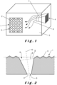
- Figure 1 illustrates schematically such an apparatus. It generally has an enclosure 3 which is provided with an air inlet 4 and an air outlet 5. Within the enclosure 3 there is an airflow 6 from the air inlet 4 to the air outlet 5.
- the different apparatuses can be divided in three groups.
- a first group comprises apparatuses which do not generate the airflow themselves.
- Those apparatuses may for example be ventilation devices which simply provide openings/channels for enabling an airflow to pass.
- the air may come for example from the outside and may flow through the ventilation device to the inside of for example a building. Noise generated outside the building, for example traffic noise, can thus be attenuated before it comes into the building.
- the apparatuses wherein the noise barrier is applied comprise at least one blower 7, in particular a ventilator, for generating the airflow 6 through the apparatus.
- Such apparatuses also produce noise.
- this noise may not only be produced by the blower 7 but also by other elements present in the apparatus.
- the apparatus may be an air blowing and/or an air sucking apparatus configured to suck in air from the environment and/or to blow air into the environment.
- the apparatus may for example be a dust collector, in particular a vacuum cleaner, the air inlet 4 of which may be at the end of a hose.
- the apparatus may also be a HVAC apparatus (Heating Ventilating Air Conditioning). These have an inlet 4 for the air and an outlet 5 for the heated, cooled or dried (or humidified) air.
- the apparatus may also be an air-cooled apparatus which comprises a device which needs to be cooled with air. It may comprise for example a combustion engine. It may also comprise a compressor, in particular an air compressor or a generator for producing electricity, which also generates heat so that these need to be cooled.
- the noise barrier 1 which is placed or which is to be placed in the path of said airflow 6, either at the location of the inlet 4, at the location of the outlet 5 or in between them, is made of a polymeric foam and has through holes 2 for enabling the airflow 6 to pass through the noise barrier 1.
- Figure 2 schematically illustrates a cross-section of the noise barrier 1 at the location of a through hole 2.
- the through hole 2 has an inlet 8 and an outlet 9 which is smaller than the inlet 8.
- the through hole 2 has a mainly conical shape. It has a centreline 10 which is defined as the imaginary axis which runs longitudinally along the through hole 2 through the midpoint of its diameter. It is the line connecting the centres of gravity of the different cross-sections through the hole 2 according to planes which are perpendicular to the centreline 10.
- the hole 2 has its smallest cross-sectional area.
- the smallest cross-sectional area of the hole 2 is at the location of its outlet 9 whilst the largest cross-sectional area of the hole 2 is at the location of its inlet 8, namely in plane ⁇ indicated in Figure 2 .
- the surface section 11 of the noise barrier 1 which is hit by the airflow 6 has been provided in Figure 2 with a surface relief, namely with pyramids.
- a plane ⁇ has been fitted to this surface section 11, more particularly to the portion of this surface section which is situated between the inlets 8 of the through holes 2. This is done by a weighted total least-squares fitting technique.
- Such a technique is for example described in point 2.1 of the article " Diagnostic-robust statistical analysis for local surface fitting in 3D point cloud data" of A. Nurunnabi et al. in ISPR Annals of the Photogrammetry, Remote Sensing and Spatial Information Sciences, Volume I-3, 2012 , which is included herein by way of reference.
- the sum of the smallest cross-sectional areas of the different through holes 2 of the noise barrier 1, i.e. the open surface of the noise barrier, is larger than 10% of the surface area of the orthogonal projection of the surface section 11 on the plane ⁇ fitted to this surface section 11. In this way, a substantial airflow 6 can pass through the noise barrier 1.
- the sum of the smallest cross-sectional areas of the different through holes 2 of the noise barrier 1 is preferably larger than 20%, more preferably larger than 30% of the surface area of the orthogonal projection of the surface section 11 on the plane ⁇ .
- the sum of the smallest cross-sectional areas of the different through holes 2 of the noise barrier 1 is preferably smaller than 60%, more preferably smaller than 50% of the surface area of the orthogonal projection of the surface section 11 on the plane ⁇ .
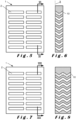
- the through holes 2 have a circular shape in a cross-section perpendicular to their centreline 10. More generally, the through holes 2 have at the location of their smallest cross-sectional areas, and measured in said planes ⁇ perpendicular to their centrelines at their smallest cross-sectional area, a longest diameter passing through said centreline and a shortest diameter passing through said centreline, which shortest diameter is larger than 30%, preferably larger than 50% of said longest diameter. In this way, the mechanical strength of the polymeric foam can be optimally maintained. This is for example the case for the honeycomb structure, illustrated in Figures 3 and 4 , wherein the through holes 2 are squared in cross-section.
- the through holes 2 are formed by elongated slots which are V-shaped in a longitudinal section through the noise barrier 1.
- two of such noise barriers are combined to achieve a noise barrier having slots which are W-shaped in a longitudinal section.
- the through holes 2 have such a shape that no straight line passes through the through holes 2. In this way, more noise is absorbed by the polymeric foam since the noise cannot pass straight through the noise barrier but instead hits the walls of the through holes 2.
- the centrelines 10 of the through holes 2 are not rectilinear and form an angle smaller than 80° with the plane ⁇ fitted to the surface of the noise barrier 1 (which coincides in the case of Figures 3 to 8 with the surface of the noise barrier 1).
- the through holes 2 are preferably cut in the polymeric foam so that the walls of the through holes are not formed by a more closed moulded skin and so that the sound absorption properties of the polymeric foam are the same at the location of the walls of the through holes. The noise is thus more effectively absorbed in the through holes themselves compared to moulded through holes.
- the noise barrier 1 is made entirely of the polymeric foam, in particular of the polyurethane foam.
- the problem to be solved with the noise barriers 1 to which the invention relates is that they should enable a sufficiently large flow of air through the noise barrier 1 while attenuating as much as possible the noise which is also transmitted along the path of the airflow.
- the noise barrier according to the present invention appeared to have better sound attenuating properties when the airflow resistivity of the polymeric foam was quite high, namely higher than 50 000 N.s/m 4 .
- Noise barriers were made having a width of 740 mm and a length of 830 mm. Transmission losses were measured in coupled room experiments following the EN ISO 15186-1 (2003) standard.
- the emission room was a reverberant room containing the source of sound
- the reception room was a hemi-anechoic room containing microphones to measure the sound intensity. The sound transmission between the two rooms only occurred through the noise barrier.
- Noise barriers having a honeycomb structure as illustrated schematically in Figures 3 and 4 were made with Foam 3 and Foam 5.
- the straight square holes had a constant cross-sectional area of about 36 cm 2 (6 ⁇ 6 cm).
- the surface area of the holes was equal to 24.7% of the total surface area of the noise barrier.
- the noise barriers were made in thicknesses of 100 mm and 200 mm.
- FIG 16 shows the transmission loss values obtained with the honey comb noise barriers having a thickness of 100 mm. It can be seen that the transmission losses that are obtained are larger for Foam 3 than for Foam 5. The transmission losses obtained with a noise barrier of 200 mm, which are shown in the graph in Figure 17 , are considerably higher. Foam 3 again offers better acoustic properties than Foam 5. This was due to the higher airflow resistivity of Foam 3. The AFR of Foam 3 was indeed about 85 000 Ns/m 4 whilst the AFR of Foam 5 was only equal to about 15 000 Ns/m 4 .
- Noise barriers having a V-shape structure as illustrated in Figures 5 and 6 were made with Foam 3 and Foam 5.
- the noise barriers had a thickness of 100 mm.
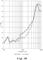
- the V-shaped slots had a width of 33 mm and their inlets (measured in the plane of the front side of the noise barrier) formed 41.1% of the total surface of the noise barrier.
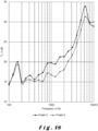
- the transmission loss values are indicated for both foams in Figure 18 . It can be seen that similar transmission loss values can be obtained as with the honeycomb structures, having the same thickness, notwithstanding the fact that the total surface area of the inlets of the slots (41.1%) is much larger than the total surface area of the inlets of the honeycomb structure (24.7%). Again, Foam 3 offered considerably better acoustic attenuating properties than Foam 5.
- Noise barriers having a W-shape structure as illustrated in Figures 7 and 8 were made with Foam 3 and Foam 5. This was done by putting two noise barriers have the V-shaped structure on top of one another. The noise barriers thus had a thickness of 200 mm.
- Cylindrical noise barriers were made having a diameter of 100 mm and a thickness of 45 mm. Transmission losses were measured following the ASTM E2611-17 standard for the transfer matrix method with the impedance tube.
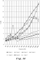
- Foams 2 and 4 showed a maximum transmission loss or a peak for frequencies around 1000 to 1250 Hz. They both had a dynamic Young's modulus of around 350 kPa. For such frequencies and higher, Foams 1 and 3 provided much better results. They had a dynamic Young's modulus respectively around 100 kPa and 150 kPa.
- Foam 1 was again the best foam, but also Foams 3 and 4, which had a lower AFR value than Foam 1, were better than the other foams.
- Foam 1 gave the best acoustic performance results
- Foam 3 may be the preferred foam material for producing the noise barrier. It has indeed a much higher static/bending Young's modulus so that the noise barrier will have a better mechanical strength to resist to the airflow. Moreover, it has a relatively low dynamic Young's modulus so that no maximum/peak is achieved in the low frequency range (see Figure 14 ) and even not at higher frequencies (apart from a small peak which may be due to resonance effects of the foam structure itself).
- Table 1 the global transmission loss values, calculated over the same frequency range as in the previous examples, namely from 80 to 2000 Hz, are given for noise barriers, made of Foam 1 and having an open surface of about 10% provided with cylindrical holes of 5 mm ( Figure 9 ), 10 mm ( Figure 10 ), 15 mm ( Figure 11a ), 20 mm ( Figure 12 ) and 25 mm ( Figure 13 ).
- Table 1 global transmission losses obtained with noise barriers made of Foam 1 having the same open surface (about 10 %) but different sizes of holes.
- Hole diameter (mm) Number of holes Global TL (in dB) 5 40 7.95 10 10 7.40 15 4 8.21 20 3 6.59 25 2 6.99
Landscapes
- Physics & Mathematics (AREA)
- Engineering & Computer Science (AREA)
- Acoustics & Sound (AREA)
- Multimedia (AREA)
- Chemical & Material Sciences (AREA)
- Aviation & Aerospace Engineering (AREA)
- Combustion & Propulsion (AREA)
- Fluid Mechanics (AREA)
- Soundproofing, Sound Blocking, And Sound Damping (AREA)
Applications Claiming Priority (2)
| Application Number | Priority Date | Filing Date | Title |
|---|---|---|---|
| EP20186431 | 2020-07-17 | ||
| PCT/EP2021/069953 WO2022013421A1 (en) | 2020-07-17 | 2021-07-16 | Noise barrier and apparatus comprising the noise barrier |
Publications (3)
| Publication Number | Publication Date |
|---|---|
| EP4182918A1 EP4182918A1 (en) | 2023-05-24 |
| EP4182918C0 EP4182918C0 (en) | 2024-06-19 |
| EP4182918B1 true EP4182918B1 (en) | 2024-06-19 |
Family
ID=71670094
Family Applications (1)
| Application Number | Title | Priority Date | Filing Date |
|---|---|---|---|
| EP21742428.2A Active EP4182918B1 (en) | 2020-07-17 | 2021-07-16 | Noise barrier and apparatus comprising the noise barrier |
Country Status (6)
| Country | Link |
|---|---|
| US (1) | US20230267905A1 (pl) |
| EP (1) | EP4182918B1 (pl) |
| CN (1) | CN116420187A (pl) |
| ES (1) | ES2985606T3 (pl) |
| PL (1) | PL4182918T3 (pl) |
| WO (1) | WO2022013421A1 (pl) |
Families Citing this family (3)
| Publication number | Priority date | Publication date | Assignee | Title |
|---|---|---|---|---|
| US20230332603A1 (en) * | 2020-10-16 | 2023-10-19 | Hitachi Industrial Equipment Systems Co., Ltd. | Package-type compressor |
| JP7737874B2 (ja) * | 2021-11-19 | 2025-09-11 | 三菱重工業株式会社 | 騒音抑制装置 |
| DE102022204585A1 (de) | 2022-05-11 | 2023-11-16 | Robert Bosch Gesellschaft mit beschränkter Haftung | Vorrichtung zum Kühlen und/oder Erwärmen eines Mediums und Abdeckung |
Family Cites Families (13)
| Publication number | Priority date | Publication date | Assignee | Title |
|---|---|---|---|---|
| US3980912A (en) * | 1975-05-27 | 1976-09-14 | Lord Corporation | Silencer for a fan-cooled electric motor |
| US5658656A (en) * | 1992-01-10 | 1997-08-19 | Minnesota Mining And Manufacturing Company | Use of materials comprising microbubbles as acoustical barriers |
| US5504281A (en) * | 1994-01-21 | 1996-04-02 | Minnesota Mining And Manufacturing Company | Perforated acoustical attenuators |
| JP2002524635A (ja) | 1998-09-17 | 2002-08-06 | ザ ダウ ケミカル カンパニー | 穴のある発泡体 |
| US6668970B1 (en) * | 2001-06-06 | 2003-12-30 | Acoustic Horizons, Inc. | Acoustic attenuator |
| US7070848B2 (en) * | 2002-10-21 | 2006-07-04 | Cascade Engineering, Inc. | Vehicle acoustic barrier |
| US7431127B2 (en) * | 2004-09-21 | 2008-10-07 | Durr Systems, Inc. | Compact noise silencer for an air blower |
| JP4935443B2 (ja) | 2007-03-19 | 2012-05-23 | 株式会社日立製作所 | 電子機器の吸音構造 |
| WO2009036784A1 (en) * | 2007-09-19 | 2009-03-26 | Henkel Ag & Co. Kgaa | Highly damping expandable material and devices |
| IT1403738B1 (it) * | 2011-02-07 | 2013-10-31 | Urbantech S R L | Assorbitore acustico ad elevate prestazioni per rendere fonoassorbenti barriere antirumore costituite da un materiale prettamente fonoisolante. |
| DE202013105639U1 (de) * | 2013-12-11 | 2014-01-15 | Dr. Schneider Kunststoffwerke Gmbh | Schallabsorbierendes Element für einen Luftausströmer |
| CA2933840C (en) * | 2013-12-19 | 2022-01-11 | Dow Global Technologies Llc | Fiber mesh reinforced shear wall |
| US20200223171A1 (en) * | 2017-10-06 | 2020-07-16 | 3M Innovative Properties Company | Acoustic composite and methods thereof |
-
2021
- 2021-07-16 ES ES21742428T patent/ES2985606T3/es active Active
- 2021-07-16 PL PL21742428.2T patent/PL4182918T3/pl unknown
- 2021-07-16 US US18/005,587 patent/US20230267905A1/en not_active Abandoned
- 2021-07-16 WO PCT/EP2021/069953 patent/WO2022013421A1/en not_active Ceased
- 2021-07-16 CN CN202180055651.9A patent/CN116420187A/zh active Pending
- 2021-07-16 EP EP21742428.2A patent/EP4182918B1/en active Active
Also Published As
| Publication number | Publication date |
|---|---|
| ES2985606T3 (es) | 2024-11-06 |
| PL4182918T3 (pl) | 2024-11-04 |
| WO2022013421A1 (en) | 2022-01-20 |
| EP4182918C0 (en) | 2024-06-19 |
| US20230267905A1 (en) | 2023-08-24 |
| CN116420187A (zh) | 2023-07-11 |
| EP4182918A1 (en) | 2023-05-24 |
Similar Documents
| Publication | Publication Date | Title |
|---|---|---|
| US20230267905A1 (en) | Noise barrier and apparatus comprising the noise barrier | |
| US9759447B1 (en) | Acoustic metamaterial noise control method and apparatus for ducted systems | |
| US10352210B2 (en) | Acoustic device | |
| CN108458467B (zh) | 分离器以及包括该分离器的消声器 | |
| US20160071507A1 (en) | Air passage type or water passage type soundproof wall having acoustic isolation resonance chamber formed in air passage channel or water passage channel | |
| CN214533437U (zh) | 消音装置及冰箱 | |
| KR101960823B1 (ko) | 무향실용 흡음구조체 및 이를 포함하는 무향실 | |
| US20210164690A1 (en) | Silencing system | |
| CN109147750A (zh) | 一种低频耦合吸声结构 | |
| US5658656A (en) | Use of materials comprising microbubbles as acoustical barriers | |
| US11097828B2 (en) | Shroud | |
| US11402123B2 (en) | Microperforated conduit | |
| US9253556B1 (en) | Dissipative system for increasing audio entropy thereby diminishing auditory perception | |
| KR20100128304A (ko) | 가스 유동 시스템 내의 가청 음향 주파수 관리를 위한 방법 | |
| CN113096626A (zh) | 静音箱 | |
| Herrin et al. | A guide to the application of microperforated panel absorbers | |
| US20190244598A1 (en) | Soundproof structure and method of manufacturing soundproof structure | |
| US20020153199A1 (en) | Sound absorbing foam | |
| KR101979378B1 (ko) | 스플리터 및 이를 포함하는 소음기 | |
| KR102904393B1 (ko) | 성형체, 흡음재, 및 진동 흡수재 | |
| CN116825063A (zh) | 声学超材料大面积短通道宽频通风隔音器和屏障 | |
| Tee et al. | Numerical analysis on vibro-acoustic characterisation of hybrid honeycomb structure with flow permeability | |
| CN112856797B (zh) | 吸音隔音复合结构及空调压缩机 | |
| CN113496692B (zh) | 用于吸声体的调频面板及包括其的吸声体和消声器 | |
| CN212618388U (zh) | 一种新型声波吹灰器 |
Legal Events
| Date | Code | Title | Description |
|---|---|---|---|
| STAA | Information on the status of an ep patent application or granted ep patent |
Free format text: STATUS: UNKNOWN |
|
| STAA | Information on the status of an ep patent application or granted ep patent |
Free format text: STATUS: THE INTERNATIONAL PUBLICATION HAS BEEN MADE |
|
| PUAI | Public reference made under article 153(3) epc to a published international application that has entered the european phase |
Free format text: ORIGINAL CODE: 0009012 |
|
| STAA | Information on the status of an ep patent application or granted ep patent |
Free format text: STATUS: REQUEST FOR EXAMINATION WAS MADE |
|
| 17P | Request for examination filed |
Effective date: 20230214 |
|
| AK | Designated contracting states |
Kind code of ref document: A1 Designated state(s): AL AT BE BG CH CY CZ DE DK EE ES FI FR GB GR HR HU IE IS IT LI LT LU LV MC MK MT NL NO PL PT RO RS SE SI SK SM TR |
|
| DAV | Request for validation of the european patent (deleted) | ||
| DAX | Request for extension of the european patent (deleted) | ||
| GRAP | Despatch of communication of intention to grant a patent |
Free format text: ORIGINAL CODE: EPIDOSNIGR1 |
|
| STAA | Information on the status of an ep patent application or granted ep patent |
Free format text: STATUS: GRANT OF PATENT IS INTENDED |
|
| GRAJ | Information related to disapproval of communication of intention to grant by the applicant or resumption of examination proceedings by the epo deleted |
Free format text: ORIGINAL CODE: EPIDOSDIGR1 |
|
| STAA | Information on the status of an ep patent application or granted ep patent |
Free format text: STATUS: REQUEST FOR EXAMINATION WAS MADE |
|
| INTG | Intention to grant announced |
Effective date: 20231109 |
|
| INTC | Intention to grant announced (deleted) | ||
| GRAP | Despatch of communication of intention to grant a patent |
Free format text: ORIGINAL CODE: EPIDOSNIGR1 |
|
| STAA | Information on the status of an ep patent application or granted ep patent |
Free format text: STATUS: GRANT OF PATENT IS INTENDED |
|
| INTG | Intention to grant announced |
Effective date: 20240117 |
|
| RAP3 | Party data changed (applicant data changed or rights of an application transferred) |
Owner name: CARPENTER ENGINEERED FOAMS BELGIUM BV |
|
| GRAS | Grant fee paid |
Free format text: ORIGINAL CODE: EPIDOSNIGR3 |
|
| GRAA | (expected) grant |
Free format text: ORIGINAL CODE: 0009210 |
|
| STAA | Information on the status of an ep patent application or granted ep patent |
Free format text: STATUS: THE PATENT HAS BEEN GRANTED |
|
| AK | Designated contracting states |
Kind code of ref document: B1 Designated state(s): AL AT BE BG CH CY CZ DE DK EE ES FI FR GB GR HR HU IE IS IT LI LT LU LV MC MK MT NL NO PL PT RO RS SE SI SK SM TR |
|
| REG | Reference to a national code |
Ref country code: GB Ref legal event code: FG4D |
|
| REG | Reference to a national code |
Ref country code: CH Ref legal event code: EP |
|
| REG | Reference to a national code |
Ref country code: DE Ref legal event code: R096 Ref document number: 602021014619 Country of ref document: DE |
|
| U01 | Request for unitary effect filed |
Effective date: 20240626 |
|
| U07 | Unitary effect registered |
Designated state(s): AT BE BG DE DK EE FI FR IT LT LU LV MT NL PT SE SI Effective date: 20240705 |
|
| PG25 | Lapsed in a contracting state [announced via postgrant information from national office to epo] |
Ref country code: HR Free format text: LAPSE BECAUSE OF FAILURE TO SUBMIT A TRANSLATION OF THE DESCRIPTION OR TO PAY THE FEE WITHIN THE PRESCRIBED TIME-LIMIT Effective date: 20240619 |
|
| PG25 | Lapsed in a contracting state [announced via postgrant information from national office to epo] |
Ref country code: GR Free format text: LAPSE BECAUSE OF FAILURE TO SUBMIT A TRANSLATION OF THE DESCRIPTION OR TO PAY THE FEE WITHIN THE PRESCRIBED TIME-LIMIT Effective date: 20240920 |
|
| U20 | Renewal fee for the european patent with unitary effect paid |
Year of fee payment: 4 Effective date: 20240925 |
|
| PG25 | Lapsed in a contracting state [announced via postgrant information from national office to epo] |
Ref country code: NO Free format text: LAPSE BECAUSE OF FAILURE TO SUBMIT A TRANSLATION OF THE DESCRIPTION OR TO PAY THE FEE WITHIN THE PRESCRIBED TIME-LIMIT Effective date: 20240919 Ref country code: HR Free format text: LAPSE BECAUSE OF FAILURE TO SUBMIT A TRANSLATION OF THE DESCRIPTION OR TO PAY THE FEE WITHIN THE PRESCRIBED TIME-LIMIT Effective date: 20240619 Ref country code: GR Free format text: LAPSE BECAUSE OF FAILURE TO SUBMIT A TRANSLATION OF THE DESCRIPTION OR TO PAY THE FEE WITHIN THE PRESCRIBED TIME-LIMIT Effective date: 20240920 Ref country code: RS Free format text: LAPSE BECAUSE OF FAILURE TO SUBMIT A TRANSLATION OF THE DESCRIPTION OR TO PAY THE FEE WITHIN THE PRESCRIBED TIME-LIMIT Effective date: 20240919 |
|
| REG | Reference to a national code |
Ref country code: ES Ref legal event code: FG2A Ref document number: 2985606 Country of ref document: ES Kind code of ref document: T3 Effective date: 20241106 |
|
| PG25 | Lapsed in a contracting state [announced via postgrant information from national office to epo] |
Ref country code: IS Free format text: LAPSE BECAUSE OF FAILURE TO SUBMIT A TRANSLATION OF THE DESCRIPTION OR TO PAY THE FEE WITHIN THE PRESCRIBED TIME-LIMIT Effective date: 20241019 |
|
| PG25 | Lapsed in a contracting state [announced via postgrant information from national office to epo] |
Ref country code: SK Free format text: LAPSE BECAUSE OF FAILURE TO SUBMIT A TRANSLATION OF THE DESCRIPTION OR TO PAY THE FEE WITHIN THE PRESCRIBED TIME-LIMIT Effective date: 20240619 |
|
| PG25 | Lapsed in a contracting state [announced via postgrant information from national office to epo] |
Ref country code: SM Free format text: LAPSE BECAUSE OF FAILURE TO SUBMIT A TRANSLATION OF THE DESCRIPTION OR TO PAY THE FEE WITHIN THE PRESCRIBED TIME-LIMIT Effective date: 20240619 |
|
| PG25 | Lapsed in a contracting state [announced via postgrant information from national office to epo] |
Ref country code: SM Free format text: LAPSE BECAUSE OF FAILURE TO SUBMIT A TRANSLATION OF THE DESCRIPTION OR TO PAY THE FEE WITHIN THE PRESCRIBED TIME-LIMIT Effective date: 20240619 Ref country code: SK Free format text: LAPSE BECAUSE OF FAILURE TO SUBMIT A TRANSLATION OF THE DESCRIPTION OR TO PAY THE FEE WITHIN THE PRESCRIBED TIME-LIMIT Effective date: 20240619 Ref country code: IS Free format text: LAPSE BECAUSE OF FAILURE TO SUBMIT A TRANSLATION OF THE DESCRIPTION OR TO PAY THE FEE WITHIN THE PRESCRIBED TIME-LIMIT Effective date: 20241019 |
|
| PG25 | Lapsed in a contracting state [announced via postgrant information from national office to epo] |
Ref country code: MC Free format text: LAPSE BECAUSE OF FAILURE TO SUBMIT A TRANSLATION OF THE DESCRIPTION OR TO PAY THE FEE WITHIN THE PRESCRIBED TIME-LIMIT Effective date: 20240619 |
|
| PG25 | Lapsed in a contracting state [announced via postgrant information from national office to epo] |
Ref country code: MC Free format text: LAPSE BECAUSE OF FAILURE TO SUBMIT A TRANSLATION OF THE DESCRIPTION OR TO PAY THE FEE WITHIN THE PRESCRIBED TIME-LIMIT Effective date: 20240619 |
|
| PLBE | No opposition filed within time limit |
Free format text: ORIGINAL CODE: 0009261 |
|
| STAA | Information on the status of an ep patent application or granted ep patent |
Free format text: STATUS: NO OPPOSITION FILED WITHIN TIME LIMIT |
|
| 26N | No opposition filed |
Effective date: 20250320 |
|
| PGFP | Annual fee paid to national office [announced via postgrant information from national office to epo] |
Ref country code: PL Payment date: 20250621 Year of fee payment: 5 |
|
| PG25 | Lapsed in a contracting state [announced via postgrant information from national office to epo] |
Ref country code: IE Free format text: LAPSE BECAUSE OF NON-PAYMENT OF DUE FEES Effective date: 20240716 |
|
| U20 | Renewal fee for the european patent with unitary effect paid |
Year of fee payment: 5 Effective date: 20250728 |
|
| PGFP | Annual fee paid to national office [announced via postgrant information from national office to epo] |
Ref country code: ES Payment date: 20250827 Year of fee payment: 5 |
|
| PGFP | Annual fee paid to national office [announced via postgrant information from national office to epo] |
Ref country code: TR Payment date: 20250708 Year of fee payment: 5 |
|
| PGFP | Annual fee paid to national office [announced via postgrant information from national office to epo] |
Ref country code: GB Payment date: 20250724 Year of fee payment: 5 |
|
| PGFP | Annual fee paid to national office [announced via postgrant information from national office to epo] |
Ref country code: CH Payment date: 20250801 Year of fee payment: 5 |
|
| PGFP | Annual fee paid to national office [announced via postgrant information from national office to epo] |
Ref country code: CZ Payment date: 20250708 Year of fee payment: 5 |
|
| PGFP | Annual fee paid to national office [announced via postgrant information from national office to epo] |
Ref country code: RO Payment date: 20250709 Year of fee payment: 5 |
|
| PG25 | Lapsed in a contracting state [announced via postgrant information from national office to epo] |
Ref country code: CY Free format text: LAPSE BECAUSE OF FAILURE TO SUBMIT A TRANSLATION OF THE DESCRIPTION OR TO PAY THE FEE WITHIN THE PRESCRIBED TIME-LIMIT; INVALID AB INITIO Effective date: 20210716 |
|
| PG25 | Lapsed in a contracting state [announced via postgrant information from national office to epo] |
Ref country code: HU Free format text: LAPSE BECAUSE OF FAILURE TO SUBMIT A TRANSLATION OF THE DESCRIPTION OR TO PAY THE FEE WITHIN THE PRESCRIBED TIME-LIMIT; INVALID AB INITIO Effective date: 20210716 |