EP4182767B1 - Membrandruckminderer - Google Patents
Membrandruckminderer Download PDFInfo
- Publication number
- EP4182767B1 EP4182767B1 EP21754830.4A EP21754830A EP4182767B1 EP 4182767 B1 EP4182767 B1 EP 4182767B1 EP 21754830 A EP21754830 A EP 21754830A EP 4182767 B1 EP4182767 B1 EP 4182767B1
- Authority
- EP
- European Patent Office
- Prior art keywords
- pressure reducer
- diaphragm
- seat
- air vent
- vent passage
- Prior art date
- Legal status (The legal status is an assumption and is not a legal conclusion. Google has not performed a legal analysis and makes no representation as to the accuracy of the status listed.)
- Active
Links
Images

Classifications
-
- E—FIXED CONSTRUCTIONS
- E03—WATER SUPPLY; SEWERAGE
- E03B—INSTALLATIONS OR METHODS FOR OBTAINING, COLLECTING, OR DISTRIBUTING WATER
- E03B7/00—Water main or service pipe systems
- E03B7/07—Arrangement of devices, e.g. filters, flow controls, measuring devices, siphons or valves, in the pipe systems
- E03B7/075—Arrangement of devices for control of pressure or flow rate
-
- F—MECHANICAL ENGINEERING; LIGHTING; HEATING; WEAPONS; BLASTING
- F16—ENGINEERING ELEMENTS AND UNITS; GENERAL MEASURES FOR PRODUCING AND MAINTAINING EFFECTIVE FUNCTIONING OF MACHINES OR INSTALLATIONS; THERMAL INSULATION IN GENERAL
- F16K—VALVES; TAPS; COCKS; ACTUATING-FLOATS; DEVICES FOR VENTING OR AERATING
- F16K24/00—Devices, e.g. valves, for venting or aerating enclosures
- F16K24/06—Devices, e.g. valves, for venting or aerating enclosures for aerating only
-
- G—PHYSICS
- G05—CONTROLLING; REGULATING
- G05D—SYSTEMS FOR CONTROLLING OR REGULATING NON-ELECTRIC VARIABLES
- G05D16/00—Control of fluid pressure
- G05D16/04—Control of fluid pressure without auxiliary power
- G05D16/06—Control of fluid pressure without auxiliary power the sensing element being a flexible membrane, yielding to pressure, e.g. diaphragm, bellows, capsule
- G05D16/063—Control of fluid pressure without auxiliary power the sensing element being a flexible membrane, yielding to pressure, e.g. diaphragm, bellows, capsule the sensing element being a membrane
- G05D16/0644—Control of fluid pressure without auxiliary power the sensing element being a flexible membrane, yielding to pressure, e.g. diaphragm, bellows, capsule the sensing element being a membrane the membrane acting directly on the obturator
- G05D16/0655—Control of fluid pressure without auxiliary power the sensing element being a flexible membrane, yielding to pressure, e.g. diaphragm, bellows, capsule the sensing element being a membrane the membrane acting directly on the obturator using one spring-loaded membrane
- G05D16/0661—Control of fluid pressure without auxiliary power the sensing element being a flexible membrane, yielding to pressure, e.g. diaphragm, bellows, capsule the sensing element being a membrane the membrane acting directly on the obturator using one spring-loaded membrane characterised by the loading mechanisms of the membrane
-
- G—PHYSICS
- G05—CONTROLLING; REGULATING
- G05D—SYSTEMS FOR CONTROLLING OR REGULATING NON-ELECTRIC VARIABLES
- G05D16/00—Control of fluid pressure
- G05D16/04—Control of fluid pressure without auxiliary power
- G05D16/06—Control of fluid pressure without auxiliary power the sensing element being a flexible membrane, yielding to pressure, e.g. diaphragm, bellows, capsule
- G05D16/063—Control of fluid pressure without auxiliary power the sensing element being a flexible membrane, yielding to pressure, e.g. diaphragm, bellows, capsule the sensing element being a membrane
- G05D16/0644—Control of fluid pressure without auxiliary power the sensing element being a flexible membrane, yielding to pressure, e.g. diaphragm, bellows, capsule the sensing element being a membrane the membrane acting directly on the obturator
- G05D16/0655—Control of fluid pressure without auxiliary power the sensing element being a flexible membrane, yielding to pressure, e.g. diaphragm, bellows, capsule the sensing element being a membrane the membrane acting directly on the obturator using one spring-loaded membrane
Definitions
- the object of the present invention is a diaphragm pressure reducer, intended to be mounted in a water system to adjust the pressure of the water in the system.
- Diaphragm pressure reducers are known that are installed on the private water network to reduce and stabilize the pressure entering from the public network.
- the pressure of the water coming from the public network is in fact normally too high and variable to be used correctly in domestic systems.
- the pressure reducer has a shutter pushed to open by a spring which is contrasted by an elastic diaphragm on which the water pressure acts to push the shutter to close.
- the diaphragm inside the body of the pressure reducer is interposed between two chambers and sealingly divides them.
- a first chamber the pressurized water that acts on the diaphragm is present, whereas air at atmospheric pressure is present in the second chamber.
- This second chamber communicates with the outside via a vent hole to avoid air being compressed therein, which would compromise the correct operation of the diaphragm.
- This rupture of the diaphragm can be caused mainly by overpressure of the water in the area of the diaphragm due for example to an increase in the water temperature in the private water network, or can also be caused by chemical corrosion because of the presence in the pressure reducer of substances used for example for disinfection.
- the object of the present invention is to propose a diaphragm pressure reducer that is able to resolve the aforesaid problem when the external devices are missing or do not work.
- the preamble of the first claim refers to JP2006318339A .
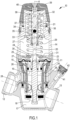
- the diaphragm pressure reducer illustrated in Fig.1 is intended to be installed in a private water network.
- the pressure reducer 10 has a hollow body 11, substantially beaker-shaped, in which a water inlet connection 12 and a water outlet connection 13 are obtained.
- the body 11 is sealingly closed above by a bell-shaped cover 14.
- a hollow insert 15 that has a central conduit 16 directed along the X axis of the pressure reducer 10, is fixed.
- the central conduit 16 is in communication with the water inlet connection 12 through suitable inner passages obtained in the insert 15 and leads into a bottom chamber 17 of the body 11 which is in turn in communication with the water outlet connection 13.
- the passage of the water from the central conduit 16 to the bottom chamber 17 is adjusted by a shutter 18 that acts on the outlet of the central conduit 16.
- a piston 19 slidable inside the central conduit 16 and connected to the shutter 18 through a rod 20 is provided.
- the rod 20 is guided inside a hollow cylinder 21 that is integral with the cover 14 inside the hollow cylinder 21.
- an elastic diaphragm 22 acts that is sealingly fixed, at the edges, to the body 11 by means of a plate 23 and sealingly fixed in a central portion to the piston 19 by means of a bush 24 and a washer 25.
- the elastic diaphragm 22 defines inside the diaphragm pressure reducer 10 a lower chamber 26 inside the body 11 and an upper chamber 27 inside the cover 14, that are sealingly separated from the diaphragm 22.
- the lower chamber 26 communicates with the bottom chamber 17 through small peripheral conduits 28 parallel to the X axis, that are obtained in the insert 15.
- a coil spring 29 acts on the elastic diaphragm 22 through a washer 30 that passes through a central hole 31 of the plate 23. On the opposite side, the spring 29 reacts on another washer, 32, screwed to the guide cylinder 21 in the upper portion of the latter.
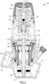
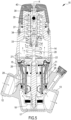
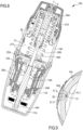
- the inside of the guide cylinder 21 has a first seat 33 in which an upper portion of the rod 20 is slidable, and a second seat 34, of lesser diameter than the first seat 33. In this second seat 34 an elastically deformable ball 35 is received having greater diameter than the diameter of this second seat 34. As shown in Figs 2,3 , the seat 34 has longitudinal peripheral channels 36 for the passage of the air.
- the inside of the cylinder 21 has moreover an air conduit 37 communicating with the seat 34 and of smaller diameter than the latter. The conduit 37 narrows at the upper end and communicates with a threaded hole 38 that opens outside.
- an adjustment knob 39 that is fixed to the cylinder 21 by means of a screw 40 that is screwed in the hole 38.
- the body 11 also has a transverse conduit 41 that leads outside and is closed by a plug 42.
- the operation of the pressure reducer 10 is the following.
- the elastic fitting of the ball 35 closes the communication gap with the hole 38, preventing the water from exiting to the outside through the threaded coupling between the hole 38 and the screw 40.
- the plug 42 can be removed and the connector of a pressure gauge can be inserted into the seat thereof, that pressure gauge is thus connected to the bottom chamber 17 through the conduit 41.
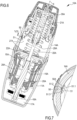
- the diaphragm pressure reducer illustrated in Fig.6 indicated generically by 10A, has a structure substantially corresponding to the pressure reducer 10 of Fig. 1 , and for this reason the same reference numbers as for the pressure reducer 10 followed by the letter A are used.
- an exhaust hole 50 obtained in the cover 14A there is an exhaust hole 50 obtained in the cover 14A.
- an elastically deformable plug 51 acts, with a substantially T-shaped section, consisting of an arched head 51.1 and of a rectilinear stem 51.2.
- the stem 51.2 is inserted into the exhaust hole 50 and has an annular projection 51.3 which interacts with a narrowing 50A of the exhaust hole 50 to keep the plug 51 constrained on the hole 50.
- the arched head 51.1 rests on the wall of the cover 14A in which the hole 50 is obtained.
- the air present in the chamber 27A in case of pressure that is greater than atmospheric pressure, vents outside through the passage that forms between the plug 51 and the hole 50, the plug 51 being simply retained on the hole 50.
- the pressurized water that flows into the chamber 27A pushes the head 51.1 of the plug 51 against the inner wall of the cover 14A, as well shown in Fig.9 where it is shown the deformation of the head 51.1 that goes to adhere to the aforesaid inner wall. In this manner, the plug 51 closes the hole 50, preventing the water from exiting the pressure reducer 10A.
- the longitudinal peripheral channels 36 for the passage of the air can also be omitted.
Landscapes
- Physics & Mathematics (AREA)
- Engineering & Computer Science (AREA)
- Fluid Mechanics (AREA)
- General Physics & Mathematics (AREA)
- Automation & Control Theory (AREA)
- General Engineering & Computer Science (AREA)
- Hydrology & Water Resources (AREA)
- Health & Medical Sciences (AREA)
- Life Sciences & Earth Sciences (AREA)
- Public Health (AREA)
- Water Supply & Treatment (AREA)
- Mechanical Engineering (AREA)
- Safety Valves (AREA)
- Making Paper Articles (AREA)
- Measuring Fluid Pressure (AREA)
Claims (5)
- Druckminderer (10) vom Membrantyp, der im Inneren einen Verschluss (18) umfasst, der den Flüssigkeitsdurchgang zwischen einem Einlass (12) und einem Auslass (13) regelt, wobei der Verschluss (18) durch eine Feder (29) zum Öffnen gedrückt wird, der eine elastische Membran (22) gegenübersteht, auf die der Flüssigkeitsdruck einwirkt, um den Verschluss (18) zum Schließen zu drücken, wobei die Membran (22) zwischen zwei Innenkammern (26, 27) des Druckminderers angeordnet ist und diese dicht trennt, wobei die auf die Membran (22) wirkende Druckflüssigkeit in einer ersten Kammer (26) vorhanden ist und eine zweite Kammer (27) durch einen Entlüftungsdurchgang mit der Außenseite in Verbindung steht, umfassend ein elastisch verformbares Element (35), das an dem Entlüftungsdurchgang im Inneren des Druckminderers angeordnet ist, wobei das elastisch verformbare Element (35) während des Normalbetriebs des Druckminderers den Luftstrom in dem Entlüftungsdurchgang ermöglicht und im Falle eines Bruchs der Membran (22) durch den Schub des Wasserdrucks verformt wird, um den vorgenannten Entlüftungskanal zu verschließen, dadurch gekennzeichnet, dass :- das elastisch verformbare Element (35) kugelförmig ist;- der Entlüftungskanal ist zylindrisch ist und das Kugelelement (35) in einem Sitz (34) des Entlüftungskanals aufgenommen wird;- sich der Durchmesser des Entlüftungskanals fortschreitend verringert, um im Falle eines Bruchs der Membran (22) die elastische Verformung des Kugelelements (35) und dessen elastische Einpassung in den Entlüftungskanal zu bestimmen und so den Entlüftungskanal zu schließen.
- Druckminderer nach Anspruch 1, wobei der Sitz (34) periphere Kanäle (36) für den Luftdurchgang aufweist.
- Druckminderer nach Anspruch 1, wobei der Verschluss (18) mit einer Stange (20) verbunden ist, die in einem Führungszylinder (21) gleitet, und wobei der Luftdurchgang im Zylinder (21) erfolgt.
- Druckminderer nach Anspruch 3, wobei das Innere des Führungszylinders (21) einen ersten Sitz (33) aufweist, in dem ein oberer Abschnitt der Stange (20) gleiten kann, und einen zweiten Sitz (34) mit kleinerem Durchmesser als der erste Sitz (33), in dem das Kugelelement (35) aufgenommen ist, wobei der Durchmesser größer ist als der Durchmesser des zweiten Sitzes (34), wobei das Innere des Führungszylinders (21) außerdem eine Luftleitung (37) aufweist, die mit dem zweiten Sitz (34) kommuniziert und einen kleineren Durchmesser hat als der Durchmesser des zweiten Sitzes (34), und wobei die Leitung (37) sich am oberen Ende verengt und mit einem Gewindeloch (38) kommuniziert, das nach außen führt und mit einer externen Befestigungsschraube (40) einer Komponente (39) des Druckminderers verbunden ist.
- Druckminderer nach Anspruch 4, wobei die Komponente ein Knopf (39) zum Einstellen der Vorspannung der Feder (29) ist.
Applications Claiming Priority (2)
| Application Number | Priority Date | Filing Date | Title |
|---|---|---|---|
| IT102020000017599A IT202000017599A1 (it) | 2020-07-20 | 2020-07-20 | Riduttore di pressione a membrana |
| PCT/IB2021/056295 WO2022018575A1 (en) | 2020-07-20 | 2021-07-13 | Diaphragm pressure reducer |
Publications (3)
| Publication Number | Publication Date |
|---|---|
| EP4182767A1 EP4182767A1 (de) | 2023-05-24 |
| EP4182767C0 EP4182767C0 (de) | 2024-08-21 |
| EP4182767B1 true EP4182767B1 (de) | 2024-08-21 |
Family
ID=73005651
Family Applications (1)
| Application Number | Title | Priority Date | Filing Date |
|---|---|---|---|
| EP21754830.4A Active EP4182767B1 (de) | 2020-07-20 | 2021-07-13 | Membrandruckminderer |
Country Status (5)
| Country | Link |
|---|---|
| US (1) | US12061488B2 (de) |
| EP (1) | EP4182767B1 (de) |
| AU (1) | AU2021311107A1 (de) |
| IT (1) | IT202000017599A1 (de) |
| WO (1) | WO2022018575A1 (de) |
Family Cites Families (12)
| Publication number | Priority date | Publication date | Assignee | Title |
|---|---|---|---|---|
| US162948A (en) * | 1875-05-04 | Improvement in gas-regulators | ||
| US2208261A (en) * | 1937-11-15 | 1940-07-16 | Sherman Jackson Roose Company | Gas pressure regulator |
| US2359111A (en) * | 1941-09-08 | 1944-09-26 | Reynolds Gas Regulator Company | Automatic vent for fluid pressure regulators |
| US2871879A (en) * | 1955-07-07 | 1959-02-03 | C A Olsen Mfg Company | Gas pressure control means |
| US3062525A (en) * | 1959-06-04 | 1962-11-06 | Penn Controls | Adjusting device for pressure regulator valve |
| US3149828A (en) * | 1962-02-13 | 1964-09-22 | Penn Controls | Adjusting device for pressure regulator valve |
| US3746263A (en) * | 1971-04-05 | 1973-07-17 | W Reeder | Weeper assembly and method for use in a slow diffusion type irrigation system |
| US4074694A (en) * | 1976-04-09 | 1978-02-21 | Leemco, Inc. | Pressure regulator with soft valve seat |
| ITMI20021879A1 (it) * | 2002-09-03 | 2004-03-04 | Cavagna Group S P A Divisione Reca Ora Cavagna Gr | Dispositivo di regolazione del flusso di gas verso l'utilizzazione. |
| JP2006318339A (ja) * | 2005-05-16 | 2006-11-24 | Yoshitake Inc | 減圧弁 |
| US9658625B2 (en) * | 2014-07-07 | 2017-05-23 | Sensus Usa Inc. | Add-on chamber for improved response of gas pressure regulators |
| US10723610B2 (en) * | 2016-09-26 | 2020-07-28 | Gate Cfv Solutions, Inc. | Magnetically controlled valve using a blocking device and a movement device |
-
2020
- 2020-07-20 IT IT102020000017599A patent/IT202000017599A1/it unknown
-
2021
- 2021-07-13 WO PCT/IB2021/056295 patent/WO2022018575A1/en not_active Ceased
- 2021-07-13 AU AU2021311107A patent/AU2021311107A1/en active Pending
- 2021-07-13 US US18/005,890 patent/US12061488B2/en active Active
- 2021-07-13 EP EP21754830.4A patent/EP4182767B1/de active Active
Also Published As
| Publication number | Publication date |
|---|---|
| WO2022018575A1 (en) | 2022-01-27 |
| EP4182767C0 (de) | 2024-08-21 |
| US12061488B2 (en) | 2024-08-13 |
| AU2021311107A1 (en) | 2023-03-02 |
| IT202000017599A1 (it) | 2022-01-20 |
| US20230315132A1 (en) | 2023-10-05 |
| EP4182767A1 (de) | 2023-05-24 |
Similar Documents
| Publication | Publication Date | Title |
|---|---|---|
| US8286660B2 (en) | Valve body with dual sense mechanism | |
| US6068022A (en) | Jet pump with improved control valve and pressure relief valve therefore | |
| US11746917B2 (en) | Pressure regulator with outlet overpressure security | |
| EP2898386B1 (de) | Ausgeglichener regler mit einer einlassdruckmesssonde | |
| JP2016157469A (ja) | 負荷調整装置とともに使用するための内部逃し弁装置 | |
| US5209253A (en) | Emergency shutoff valve and regulator assembly | |
| EP2689169B1 (de) | Haubenvorrichtung zur verwendung mit flüssigkeitsregulatoren | |
| US9581354B2 (en) | Relief valve | |
| JPH0242284A (ja) | 高温用安全逃し装置 | |
| EP3108320B1 (de) | Ausgeglichener regler mit ausgeglichener trimmung mit variablem druckempfindlichem bereich | |
| US20040065368A1 (en) | Internally piloted dome loaded regulator | |
| EP3226097A1 (de) | Axialventil zur kontrolle des differnezdrucks zwischen einem vorlauf- und einem rücklaufzweig einer hydraulischen schaltung | |
| EP4182767B1 (de) | Membrandruckminderer | |
| US6675824B2 (en) | Valve with wilder opening and pressure regulator equipped with such a valve | |
| US4111223A (en) | Control line relief valve | |
| WO2016130129A1 (en) | Relief valve | |
| US11035482B2 (en) | Pressure relief valve | |
| US11668405B2 (en) | Fluid dispensing device with safety valve | |
| JP7190732B2 (ja) | 減圧弁 | |
| JP2022140159A (ja) | 減圧弁 |
Legal Events
| Date | Code | Title | Description |
|---|---|---|---|
| STAA | Information on the status of an ep patent application or granted ep patent |
Free format text: STATUS: UNKNOWN |
|
| STAA | Information on the status of an ep patent application or granted ep patent |
Free format text: STATUS: THE INTERNATIONAL PUBLICATION HAS BEEN MADE |
|
| PUAI | Public reference made under article 153(3) epc to a published international application that has entered the european phase |
Free format text: ORIGINAL CODE: 0009012 |
|
| STAA | Information on the status of an ep patent application or granted ep patent |
Free format text: STATUS: REQUEST FOR EXAMINATION WAS MADE |
|
| 17P | Request for examination filed |
Effective date: 20230217 |
|
| AK | Designated contracting states |
Kind code of ref document: A1 Designated state(s): AL AT BE BG CH CY CZ DE DK EE ES FI FR GB GR HR HU IE IS IT LI LT LU LV MC MK MT NL NO PL PT RO RS SE SI SK SM TR |
|
| DAV | Request for validation of the european patent (deleted) | ||
| DAX | Request for extension of the european patent (deleted) | ||
| GRAP | Despatch of communication of intention to grant a patent |
Free format text: ORIGINAL CODE: EPIDOSNIGR1 |
|
| STAA | Information on the status of an ep patent application or granted ep patent |
Free format text: STATUS: GRANT OF PATENT IS INTENDED |
|
| RIC1 | Information provided on ipc code assigned before grant |
Ipc: F16K 24/06 20060101ALI20240212BHEP Ipc: G05D 16/06 20060101AFI20240212BHEP |
|
| INTG | Intention to grant announced |
Effective date: 20240314 |
|
| GRAS | Grant fee paid |
Free format text: ORIGINAL CODE: EPIDOSNIGR3 |
|
| GRAA | (expected) grant |
Free format text: ORIGINAL CODE: 0009210 |
|
| STAA | Information on the status of an ep patent application or granted ep patent |
Free format text: STATUS: THE PATENT HAS BEEN GRANTED |
|
| AK | Designated contracting states |
Kind code of ref document: B1 Designated state(s): AL AT BE BG CH CY CZ DE DK EE ES FI FR GB GR HR HU IE IS IT LI LT LU LV MC MK MT NL NO PL PT RO RS SE SI SK SM TR |
|
| REG | Reference to a national code |
Ref country code: GB Ref legal event code: FG4D |
|
| REG | Reference to a national code |
Ref country code: CH Ref legal event code: EP |
|
| REG | Reference to a national code |
Ref country code: IE Ref legal event code: FG4D |
|
| REG | Reference to a national code |
Ref country code: DE Ref legal event code: R096 Ref document number: 602021017594 Country of ref document: DE |
|
| U01 | Request for unitary effect filed |
Effective date: 20240920 |
|
| U07 | Unitary effect registered |
Designated state(s): AT BE BG DE DK EE FI FR IT LT LU LV MT NL PT RO SE SI Effective date: 20241018 |
|
| PG25 | Lapsed in a contracting state [announced via postgrant information from national office to epo] |
Ref country code: NO Free format text: LAPSE BECAUSE OF FAILURE TO SUBMIT A TRANSLATION OF THE DESCRIPTION OR TO PAY THE FEE WITHIN THE PRESCRIBED TIME-LIMIT Effective date: 20241121 |
|
| PG25 | Lapsed in a contracting state [announced via postgrant information from national office to epo] |
Ref country code: PL Free format text: LAPSE BECAUSE OF FAILURE TO SUBMIT A TRANSLATION OF THE DESCRIPTION OR TO PAY THE FEE WITHIN THE PRESCRIBED TIME-LIMIT Effective date: 20240821 Ref country code: GR Free format text: LAPSE BECAUSE OF FAILURE TO SUBMIT A TRANSLATION OF THE DESCRIPTION OR TO PAY THE FEE WITHIN THE PRESCRIBED TIME-LIMIT Effective date: 20241122 |
|
| PG25 | Lapsed in a contracting state [announced via postgrant information from national office to epo] |
Ref country code: IS Free format text: LAPSE BECAUSE OF FAILURE TO SUBMIT A TRANSLATION OF THE DESCRIPTION OR TO PAY THE FEE WITHIN THE PRESCRIBED TIME-LIMIT Effective date: 20241221 |
|
| PG25 | Lapsed in a contracting state [announced via postgrant information from national office to epo] |
Ref country code: HR Free format text: LAPSE BECAUSE OF FAILURE TO SUBMIT A TRANSLATION OF THE DESCRIPTION OR TO PAY THE FEE WITHIN THE PRESCRIBED TIME-LIMIT Effective date: 20240821 |
|
| PG25 | Lapsed in a contracting state [announced via postgrant information from national office to epo] |
Ref country code: RS Free format text: LAPSE BECAUSE OF FAILURE TO SUBMIT A TRANSLATION OF THE DESCRIPTION OR TO PAY THE FEE WITHIN THE PRESCRIBED TIME-LIMIT Effective date: 20241121 Ref country code: ES Free format text: LAPSE BECAUSE OF FAILURE TO SUBMIT A TRANSLATION OF THE DESCRIPTION OR TO PAY THE FEE WITHIN THE PRESCRIBED TIME-LIMIT Effective date: 20240821 |
|
| PG25 | Lapsed in a contracting state [announced via postgrant information from national office to epo] |
Ref country code: RS Free format text: LAPSE BECAUSE OF FAILURE TO SUBMIT A TRANSLATION OF THE DESCRIPTION OR TO PAY THE FEE WITHIN THE PRESCRIBED TIME-LIMIT Effective date: 20241121 Ref country code: PL Free format text: LAPSE BECAUSE OF FAILURE TO SUBMIT A TRANSLATION OF THE DESCRIPTION OR TO PAY THE FEE WITHIN THE PRESCRIBED TIME-LIMIT Effective date: 20240821 Ref country code: NO Free format text: LAPSE BECAUSE OF FAILURE TO SUBMIT A TRANSLATION OF THE DESCRIPTION OR TO PAY THE FEE WITHIN THE PRESCRIBED TIME-LIMIT Effective date: 20241121 Ref country code: IS Free format text: LAPSE BECAUSE OF FAILURE TO SUBMIT A TRANSLATION OF THE DESCRIPTION OR TO PAY THE FEE WITHIN THE PRESCRIBED TIME-LIMIT Effective date: 20241221 Ref country code: HR Free format text: LAPSE BECAUSE OF FAILURE TO SUBMIT A TRANSLATION OF THE DESCRIPTION OR TO PAY THE FEE WITHIN THE PRESCRIBED TIME-LIMIT Effective date: 20240821 Ref country code: GR Free format text: LAPSE BECAUSE OF FAILURE TO SUBMIT A TRANSLATION OF THE DESCRIPTION OR TO PAY THE FEE WITHIN THE PRESCRIBED TIME-LIMIT Effective date: 20241122 Ref country code: ES Free format text: LAPSE BECAUSE OF FAILURE TO SUBMIT A TRANSLATION OF THE DESCRIPTION OR TO PAY THE FEE WITHIN THE PRESCRIBED TIME-LIMIT Effective date: 20240821 |
|
| PG25 | Lapsed in a contracting state [announced via postgrant information from national office to epo] |
Ref country code: SM Free format text: LAPSE BECAUSE OF FAILURE TO SUBMIT A TRANSLATION OF THE DESCRIPTION OR TO PAY THE FEE WITHIN THE PRESCRIBED TIME-LIMIT Effective date: 20240821 |
|
| PG25 | Lapsed in a contracting state [announced via postgrant information from national office to epo] |
Ref country code: CZ Free format text: LAPSE BECAUSE OF FAILURE TO SUBMIT A TRANSLATION OF THE DESCRIPTION OR TO PAY THE FEE WITHIN THE PRESCRIBED TIME-LIMIT Effective date: 20240821 |
|
| PG25 | Lapsed in a contracting state [announced via postgrant information from national office to epo] |
Ref country code: SK Free format text: LAPSE BECAUSE OF FAILURE TO SUBMIT A TRANSLATION OF THE DESCRIPTION OR TO PAY THE FEE WITHIN THE PRESCRIBED TIME-LIMIT Effective date: 20240821 |
|
| PLBE | No opposition filed within time limit |
Free format text: ORIGINAL CODE: 0009261 |
|
| STAA | Information on the status of an ep patent application or granted ep patent |
Free format text: STATUS: NO OPPOSITION FILED WITHIN TIME LIMIT |
|
| 26N | No opposition filed |
Effective date: 20250522 |
|
| U20 | Renewal fee for the european patent with unitary effect paid |
Year of fee payment: 5 Effective date: 20250731 |
|
| PGFP | Annual fee paid to national office [announced via postgrant information from national office to epo] |
Ref country code: GB Payment date: 20250728 Year of fee payment: 5 |