EP4182558B1 - Windkraftanlage mit generatorgetriebe und rotorwellenanordnung - Google Patents
Windkraftanlage mit generatorgetriebe und rotorwellenanordnung Download PDFInfo
- Publication number
- EP4182558B1 EP4182558B1 EP21740569.5A EP21740569A EP4182558B1 EP 4182558 B1 EP4182558 B1 EP 4182558B1 EP 21740569 A EP21740569 A EP 21740569A EP 4182558 B1 EP4182558 B1 EP 4182558B1
- Authority
- EP
- European Patent Office
- Prior art keywords
- rotor shaft
- output shaft
- curved
- shaft
- wind turbine
- Prior art date
- Legal status (The legal status is an assumption and is not a legal conclusion. Google has not performed a legal analysis and makes no representation as to the accuracy of the status listed.)
- Active
Links
Images
Classifications
-
- F—MECHANICAL ENGINEERING; LIGHTING; HEATING; WEAPONS; BLASTING
- F03—MACHINES OR ENGINES FOR LIQUIDS; WIND, SPRING, OR WEIGHT MOTORS; PRODUCING MECHANICAL POWER OR A REACTIVE PROPULSIVE THRUST, NOT OTHERWISE PROVIDED FOR
- F03D—WIND MOTORS
- F03D15/00—Transmission of mechanical power
-
- F—MECHANICAL ENGINEERING; LIGHTING; HEATING; WEAPONS; BLASTING
- F16—ENGINEERING ELEMENTS AND UNITS; GENERAL MEASURES FOR PRODUCING AND MAINTAINING EFFECTIVE FUNCTIONING OF MACHINES OR INSTALLATIONS; THERMAL INSULATION IN GENERAL
- F16D—COUPLINGS FOR TRANSMITTING ROTATION; CLUTCHES; BRAKES
- F16D3/00—Yielding couplings, i.e. with means permitting movement between the connected parts during the drive
- F16D3/16—Universal joints in which flexibility is produced by means of pivots or sliding or rolling connecting parts
- F16D3/18—Universal joints in which flexibility is produced by means of pivots or sliding or rolling connecting parts the coupling parts (1) having slidably-interengaging teeth
- F16D3/185—Universal joints in which flexibility is produced by means of pivots or sliding or rolling connecting parts the coupling parts (1) having slidably-interengaging teeth radial teeth connecting concentric inner and outer coupling parts
-
- B—PERFORMING OPERATIONS; TRANSPORTING
- B33—ADDITIVE MANUFACTURING TECHNOLOGY
- B33Y—ADDITIVE MANUFACTURING, i.e. MANUFACTURING OF THREE-DIMENSIONAL [3D] OBJECTS BY ADDITIVE DEPOSITION, ADDITIVE AGGLOMERATION OR ADDITIVE LAYERING, e.g. BY 3D PRINTING, STEREOLITHOGRAPHY OR SELECTIVE LASER SINTERING
- B33Y50/00—Data acquisition or data processing for additive manufacturing
-
- F—MECHANICAL ENGINEERING; LIGHTING; HEATING; WEAPONS; BLASTING
- F05—INDEXING SCHEMES RELATING TO ENGINES OR PUMPS IN VARIOUS SUBCLASSES OF CLASSES F01-F04
- F05B—INDEXING SCHEME RELATING TO WIND, SPRING, WEIGHT, INERTIA OR LIKE MOTORS, TO MACHINES OR ENGINES FOR LIQUIDS COVERED BY SUBCLASSES F03B, F03D AND F03G
- F05B2250/00—Geometry
- F05B2250/20—Geometry three-dimensional
- F05B2250/24—Geometry three-dimensional ellipsoidal
- F05B2250/241—Geometry three-dimensional ellipsoidal spherical
-
- F—MECHANICAL ENGINEERING; LIGHTING; HEATING; WEAPONS; BLASTING
- F05—INDEXING SCHEMES RELATING TO ENGINES OR PUMPS IN VARIOUS SUBCLASSES OF CLASSES F01-F04
- F05B—INDEXING SCHEME RELATING TO WIND, SPRING, WEIGHT, INERTIA OR LIKE MOTORS, TO MACHINES OR ENGINES FOR LIQUIDS COVERED BY SUBCLASSES F03B, F03D AND F03G
- F05B2260/00—Function
- F05B2260/40—Transmission of power
- F05B2260/403—Transmission of power through the shape of the drive components
- F05B2260/4031—Transmission of power through the shape of the drive components as in toothed gearing
- F05B2260/40311—Transmission of power through the shape of the drive components as in toothed gearing of the epicyclic, planetary or differential type
-
- F—MECHANICAL ENGINEERING; LIGHTING; HEATING; WEAPONS; BLASTING
- F16—ENGINEERING ELEMENTS AND UNITS; GENERAL MEASURES FOR PRODUCING AND MAINTAINING EFFECTIVE FUNCTIONING OF MACHINES OR INSTALLATIONS; THERMAL INSULATION IN GENERAL
- F16H—GEARING
- F16H57/00—General details of gearing
- F16H57/02—Gearboxes; Mounting gearing therein
- F16H2057/02039—Gearboxes for particular applications
- F16H2057/02078—Gearboxes for particular applications for wind turbines
-
- Y—GENERAL TAGGING OF NEW TECHNOLOGICAL DEVELOPMENTS; GENERAL TAGGING OF CROSS-SECTIONAL TECHNOLOGIES SPANNING OVER SEVERAL SECTIONS OF THE IPC; TECHNICAL SUBJECTS COVERED BY FORMER USPC CROSS-REFERENCE ART COLLECTIONS [XRACs] AND DIGESTS
- Y02—TECHNOLOGIES OR APPLICATIONS FOR MITIGATION OR ADAPTATION AGAINST CLIMATE CHANGE
- Y02E—REDUCTION OF GREENHOUSE GAS [GHG] EMISSIONS, RELATED TO ENERGY GENERATION, TRANSMISSION OR DISTRIBUTION
- Y02E10/00—Energy generation through renewable energy sources
- Y02E10/70—Wind energy
- Y02E10/72—Wind turbines with rotation axis in wind direction
Definitions
- the invention relates to a wind turbine with a multi-blade rotor, which is rotatably arranged on a nacelle and is connected to a generator transmission via a main shaft in a torque-transmitting manner, the generator transmission having a transmission unit and a generator unit detachably connected thereto, which transmits torque via a rotor shaft arrangement with an output shaft and a rotor shaft are connected to each other.
- the publication US 2011/272214 A1 discloses a generator transmission that includes a transmission unit and a generator unit.
- a sun shaft of a planetary stage is provided with teeth at one end on the generator side, which belong to a clutch that establishes a connection to a rotor shaft.
- the coupling is curved to compensate for an offset between the sun shaft and the rotor shaft.
- the rotor shaft is mounted radially from the toothing via bearings that can support any axial forces that occur.
- the International Patent Application WO 02/081280 A1 shows a vehicle drive in which a rotor shaft of a drive motor is connected to a gearbox via a curved tooth clutch.
- the rotor shaft is housed in the curved tooth coupling in an internally toothed component that is connected to a gear pinion.
- Curved tooth couplings are known in which covers are arranged next to the curved teeth at the axial ends of a coupling intermediate piece. The covers ensure that the curved tooth coupling is sealed against the escape of lubricant.
- a wind turbine with a multi-blade rotor which is rotatably arranged on a nacelle and is connected to a generator gearbox in a torque-transmitting manner via a main shaft, whereby the generator transmission comprises a transmission unit and a generator unit detachably connected thereto, which are connected to one another in a torque-transmitting manner via a rotor shaft arrangement.
- the rotor shaft assembly includes an output shaft for the transmission unit and a rotor shaft for the generator unit. When assembled, the transmission unit and the generator unit are connected to each other in a torque-transmitting manner using a curved tooth clutch. For this purpose, the curved tooth coupling is connected to the output shaft and the rotor shaft.
- the output shaft can be partially accommodated in the rotor shaft by means of the curved tooth coupling or the rotor shaft can be partially accommodated in the output shaft by means of the curved tooth coupling.
- the curved tooth coupling also includes at least one support element.
- the at least one support element is designed for axial positioning of the curved tooth coupling and is releasably attached.
- the at least one support element is designed to limit a relative axial mobility of the curved tooth clutch, and thus of the rotor shaft, with respect to the output shaft.
- the at least one support element has a counter surface which supports axial forces of the curved tooth coupling, the counter surface being designed to be slidable on a corresponding support surface of the output shaft or the rotor shaft when the output shaft is tilted relative to the rotor shaft.
- This allows the output shaft to tilt relative to the rotor shaft in order to compensate for an angular offset, while at the same time a transfer of axial forces is provided via the at least one support element in order to limit an axial relative movement of the output shaft to the rotor shaft and in particular an axial migration of the output shaft to prevent a torque-transmitting coupling with the rotor shaft. Accordingly, axial migration of the rotor shaft on the output shaft can be avoided during operation.
- the curved tooth clutch can be designed to be compact along an axial direction, i.e. essentially along a main axis of rotation of the transmission unit and/or generator unit.
- the rotor shaft can also be accommodated in a floating bearing.
- the axial positioning of the curved tooth coupling ensures smooth mobility and enables adjustable, in particular angularly adjustable, behavior between the output shaft and the rotor shaft.
- the at least one support element can be produced separately in a simple manner and allows quick assembly and disassembly of a generator gear with a gear unit and generator unit.
- the at least one support element can comprise a first support element and/or a second support element.
- the quantity of the at least one support element can include exactly one first support element, exactly one second support element and both the first support element and the second support element.
- only the first support element and the second support element are provided at the same time, so that a third support element and further support elements are avoided.
- first support element and the second support element are provided at different axial ends of the curved tooth coupling, wherein in particular the first support element and the second support element can be moved towards one another during assembly with a proportion of movement in the axial direction in order to ensure axial play of the rotor shaft with respect to the output shaft, particularly in the area of the curved tooth coupling, to eliminate or limit it to a predefined axial play, for example in order to provide an axial clearance fit and/or to be able to compensate for axial thermal expansion of the rotor shaft and/or output shaft that is expected during operation.
- the first support element and the second support element can be provided at a predefined axial distance from one another.
- the axial relative position of the support elements relative to the rotor shaft and the output shaft is not predefined, but instead depends on an angular offset to be compensated for by the curved tooth coupling.
- a support point of the respective support element pointing away from the curved tooth coupling can be designed to be axially displaceable, for example with the help of a with the rotor shaft or with the screwing device acting on the output shaft.
- the at least one support element in particular the first support element and/or the second support element, has the counter surface that can be slid on the curved tooth coupling when the output shaft tilts relative to the rotor shaft to compensate for an angular offset with the aid of the curved tooth coupling, which can slide on the corresponding support surface of the output shaft or the rotor shaft in the area of the curved tooth coupling.
- the curved tooth coupling can have a curved area that is provided with a toothing in an inner part and forms the support surface that interacts with the at least one support element in an outer part that adjoins the inner part through the output shaft or the rotor shaft.
- the support surface is preferably formed by an untoothed curved area of the coupling partner of the curved tooth coupling formed by the output shaft or the rotor shaft.
- the support surface and the counter surface are designed as spherical caps that can slide on one another, in particular ring-shaped.
- the support surface and the curved tooth coupling can slide on one another in the manner of a ball socket bearing.
- the output shaft is tilt relative to the rotor shaft in order to compensate for an angular offset, while at the same time the transfer of axial forces is provided via the at least one support element in order to limit an axial relative movement of the output shaft to the rotor shaft and in particular to prevent the output shaft from axially drifting away from a torque-transmitting coupling with the rotor shaft.
- the output shaft is coupled to the rotor shaft in an axially captive manner by the at least one support element.
- first support element and the second support element with the associated support surfaces form a ball joint bearing for the curved tooth coupling.
- Axial play can be minimized in this way, At the same time, tilting of the output shaft relative to the rotor shaft is permitted to compensate for an angular misalignment, but occurring axial forces can already be supported in the area of the curved tooth coupling on the formed ball joint bearing.
- the at least one support element forms an axial play of the output shaft relative to the rotor shaft to compensate for axial thermal expansions to be expected during operation.
- an axial play in particular of the order of a clearance fit, is provided between the respective support surfaces and the mating surface of the respective support element which interacts with the respective support surface, so that the curved tooth coupling cannot jam between the first support element and the second support element when thermal expansion effects are to be expected.
- a first support element is arranged on a side of the curved tooth clutch facing the gear unit. Accordingly, the mobility between the rotor shaft and the output shaft can be easily restricted on one side and the curved tooth coupling can be centered in a proper position.
- a second support element can be arranged on a side of the curved tooth coupling facing the generator unit. This means that the mobility between the rotor shaft and the output shaft can be easily restricted on one side. This also puts the curved tooth coupling in a proper position, which ensures smooth angle adjustment between the rotor shaft and the output shaft.
- a combination of the first and second support elements offers particularly precise axial positioning of the curved tooth coupling.
- the support elements also determine the angular offset between the rotor shaft and the output shaft. A correspondingly precise axial positioning of the curved tooth coupling allows its teeth to engage optimally to hold, thereby enabling increased transmission of torque while ensuring angle adjustability. Furthermore, the first and second support elements support an axial load that acts on the output shaft. The axial load acting on the output shaft depends on the pitch of a helical gear that introduces torque into the output shaft.
- At least one support surface can be formed on the output shaft or the rotor shaft.
- the support surface is designed to support the at least one support element.
- the support surface is an area of the output shaft or the rotor shaft which is designed in terms of shape and hardness to be suitable for contact with the at least one support element.
- the support surface can be formed integrally with the output shaft or the rotor shaft or as an area of a separate, detachably mounted component.
- a support surface formed integrally with the rotor shaft or output shaft can be manufactured with increased accuracy, which ensures precise axial positioning of the curved tooth coupling.
- a support surface formed on a separate component enables cost-efficient separate production and easy interchangeability. Furthermore, a particularly high-performance and cost-intensive material can be used in accordance with requirements and therefore economically.
- the at least one support surface is designed as a shoulder in the area of a curved toothing, which belongs to the curved tooth coupling.
- the shoulder can be connected directly to the curved toothing and/or arranged directly adjacent to it.
- Curved teeth can be formed in one piece with the rotor shaft and/or the output shaft, which ensures that the curved teeth can withstand particular stress.
- a shoulder that is suitable as a support surface can be easily integrated into an existing manufacturing process.
- the shoulder is suitable for ensuring load introduction into the rotor shaft or output shaft in accordance with the load.
- shoulders on the rotor shaft or output shaft can be adjusted in terms of curvature.
- the rotor shaft arrangement can be adapted to different mechanical stresses and different space requirements.
- the rotor shaft arrangement is accordingly scalable and has a wide range of uses.
- the at least one detachably attached support element can have an at least partially circumferentially concave section of the counter surface for axially positioning the curved tooth coupling.
- the concave section serves as a counterpart to the support surface, which is arranged opposite it.
- the at least partially circumferentially concave section of the support element can be designed to correspond with a spherical section, i.e. can be spherical.
- the support surface can be at least partially circumferentially convex.
- the support surface can be convex to correspond with the support element, so that precise guidance is ensured when an angular offset occurs between the rotor shaft and the output shaft.
- the support surface can be designed to correspond with a spherical section, i.e. can have a spherical shape. Such shapes can be manufactured precisely and cost-effectively and offer high mechanical strength.
- the at least partially circumferentially convex The support surface and/or the at least partially circumferentially concave section of the support element can have a common center point that corresponds to a tilting axis of the curved tooth coupling. This ensures in particular a consistently smooth angle adjustment between the rotor shaft and the output shaft.
- the output shaft and/or the rotor shaft can be designed as a hollow shaft.
- An output shaft and/or rotor shaft designed as a hollow shaft allows the other shaft to be accommodated and/or another shaft, such as a pitch tube, to be passed through.
- the rotor shaft arrangement can thus be designed to be compact in the axial direction.
- a rotor in the generator unit can be placed close to the gear unit in the axial direction.
- the rotor shaft can also be designed as a separate component that can be easily connected to other rotor components.
- the curved toothing on the output shaft is designed as external toothing or as internal toothing.
- the curved toothing on the rotor shaft is designed as internal toothing or as external toothing.
- a curved tooth coupling designed in this way offers high mechanical strength for transmitting torque in a compact manner and allows easy assembly.
- the at least one support element and the support surface can be at least partially made of different materials.
- the support element can be made from a plain bearing material or can be provided with a plain bearing material. This can be implemented, for example, with a friction-reducing coating. With a support surface that is made, for example, from a steel or a steel alloy, there is reduced friction between the support surface and the support element, which in turn leads to reduced wear.
- the support surface and/or the support element can be heat treated, whereby the friction present there is further reduced.
- the support surface can also be made at least partially from a plain bearing material or can be provided with plain bearing material.
- the output shaft can be designed as a sun shaft of a planetary stage of the transmission unit.
- the rotor shaft can be designed as a hollow shaft.
- the output shaft forms external teeth for the curved tooth clutch, while the rotor shaft forms internal teeth for the curved tooth clutch.
- the entire curved tooth coupling is therefore formed radially within the rotor shaft.
- the rotor shaft arrangement thereby allows the gear unit to be connected in a simple manner to the generator unit of a corresponding gear generator.
- the transmission unit is coupled to one another directly on the output side via the output shaft and the generator unit on the input side via the rotor shaft, that is, without interposed torque-transmitting components.
- the output shaft can be partially inserted into the interior of the rotor shaft designed as a hollow shaft, so that the rotor shaft, viewed in the radial direction, can cover part of the output shaft and in particular the entire curved toothing.
- the rotor shaft is directly connected to the rotor and can be mounted on the output shaft. This avoids complicated handling of the entire generator unit, which also includes a housing. The production of a gear generator with gear unit and generator unit is consequently accelerated and can therefore be carried out cost-effectively.
- the transmission unit is suitable for being connected directly, i.e. without a separate clutch, to a generator unit to form a generator gearbox, so that they form an integrated unit.
- the transmission unit in particular includes at least one planetary stage, i.e.
- the at least one planetary stage has a shaft which is connected to a rotatable transmission component, i.e. a sun gear, a planetary carrier or a ring gear of the planetary stage, and serves as an output shaft of the transmission unit.
- a curved toothing is formed on a section facing the generator unit, which is suitable for forming a curved tooth clutch.
- at least one support surface is formed, which is suitable for adjustable axial positioning of the curved toothing in the curved tooth coupling.
- Adjustable axial positioning means that an angular offset between the output shaft and a rotor shaft connected to it in the assembled state can be compensated for by the curved tooth coupling.
- the adjustment mobility can be an angular adjustment mobility.
- Axial positioning also means holding the curved toothing in a position that ensures easy angular adjustment between the output shaft and the rotor shaft.
- the transmission unit is designed to be combined with a rotor shaft arrangement according to at least one of the embodiments outlined above.
- the transmission unit has three or more planetary stages connected in series.
- a series connection is a torque-transmitting connection between the planetary stages, through which a drive power supplied to the transmission unit is carried out without branching.
- Such series connections are described, among other things, in the international application WO 2020/001942 A1 disclosed.
- the gear unit offers a high level of mechanical performance with a compact design, reduced weight and high cost-effectiveness.
- the underlying task is solved by a non-claimed computer program product that is designed to simulate an operating behavior of a rotor shaft arrangement.
- the computer program product can include data on the kinematics of the output shaft, the rotor shaft and the curved tooth coupling.
- the computer program product can include simulation routines that are designed to determine a vibration behavior of the rotor shaft arrangement based on information on the dimensions of the rotor shaft, the output shaft and/or the curved tooth coupling.
- the computer program product can also have a data interface via which operating parameters, such as a speed of the output shaft, a torque transported via the output shaft, or orientation of the output shaft, can be specified.
- the computer program product can also have a data interface for outputting simulation results.
- the rotor shaft arrangement is designed according to at least one of the embodiments outlined above.
- the computer program product can be designed, for example, as a so-called digital twin. Such digital twins are described, among other things, in the published patent application US 2017/0286572 A1 shown.
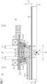
- FIG 1 is a schematic longitudinal section of a first embodiment a rotor shaft arrangement 30 is shown, which comprises an output shaft 10, which is designed as a hollow shaft 11, and a rotor shaft 20, which is also designed as a hollow shaft 21 and is rotatably received in rotor shaft bearings 28 on a housing 34, not shown in detail.
- a torque 25 is supplied via the output shaft 10 with respect to a main axis of rotation 15, which torque is applied to the Rotor shaft 20 is to be transmitted.
- the output shaft 10 is assigned to a gear unit 51 (not shown in detail) on a gear side 31 and the rotor shaft 20 to a generator unit 53 (not shown in detail) on a generator side 33.
- the output shaft 10 is provided with a curved toothing 12 on an end facing the generator side 33, which is designed as an external toothing 13.
- the rotor shaft 20 is correspondingly provided with a curved toothing 22, which is designed as an internal toothing 23 and meshes with the curved toothing 12 of the rotor shaft 10.
- the curved toothings 12, 22 on the output shaft 10 and the rotor shaft 20 thus belong to a curved tooth coupling 40, which allows an angular offset between the output shaft 10 and the rotor shaft 20 about a pivot point 45.
- the angular offset can be adjusted for the output shaft 10 and the rotor shaft 20 in relation to the main axis of rotation 15. This achieves an angle adjustment mobility 49 which FIG 1 symbolized by the correspondingly designated double arrow.
- a vertex 17 of the curved toothing 12 on the output shaft 10 and a vertex 27 of the curved toothing 22 on the rotor shaft 20 are positioned substantially flush in a radial direction 37.
- the curved tooth coupling 40 also includes support elements 42, which are designed to be circumferential and are arranged in the area of the curved toothings 12, 22. When assembled, the support elements 42 are fastened with locking rings 48. The support elements 42 are detachably mounted, with a first support element 44, based on the curved tooth clutch 40, being arranged on the transmission side 31 and a second support element 46 on the generator side 33. By arranging the support elements 42, 44, 46 in an area 41 of the Curved toothings 12, 22, the angular adjustment mobility 49, i.e. the maximum achievable angular offset, is determined.
- the support elements 42, 44, 46 each have a counter surface 43, which is circumferential and essentially concave, and is arranged opposite a support surface 16 on the output shaft 10 is.
- the support surfaces 16 are formed in one piece with the output shaft 10 and each belong to a shoulder 18, which is also formed in one piece with the output shaft 10.
- the support surfaces 16 are each essentially convex, with the shape of the support surfaces 16 corresponding to the concave shape of the counter surfaces 43 on the rotor shaft 20.
- the support surfaces 16 and the counter surfaces 43 are spherical and have the pivot point 45 of the angle adjustability 49 as the center point. Such a spherical shape of the curved tooth coupling 40 offers particular ease of movement for the angle adjustability 49.
- At least one of the support elements 42, 44, 46 in the area of the counter surface 43 must be made of a different material than a corresponding support surface 16 on the output shaft 10. At least one of the support elements 42, 44, 46 is made of a plain bearing material, which minimizes friction between the corresponding support surface 16 and the support element 42, 44, 46.
- the curved tooth coupling 40 i.e. the curved toothings 12, 22, is positioned on the output shaft 10 and the rotor shaft 20 along an axial direction 35 by the support elements 42, 44, 46. The axial positioning by the support elements 42, 44, 46 ensures that the curved toothings 12, 22 are minimized in width, i.e. their dimensions along the axial direction 35.
- a pitch tube 36 is rotatably accommodated in the output shaft 10 designed as a hollow shaft 11.
- a generator-side end face 14 of the output shaft 10 lies along the axial direction 35 in the area of the rotor shaft 20.
- the output shaft 10 is thus arranged without bearings on the generator side 33, which in turn reduces the number of components in the rotor shaft arrangement 30 and simplifies its assembly.
- the rotor shaft assembly 30 in FIG 1 is further reproduced in a computer program product 80, which is designed to simulate the operating behavior of the rotor shaft arrangement 30.
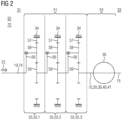
- FIG 2 A first embodiment of a generator gear 50 is shown in FIG 2 shown schematically in their structure.
- the generator gear 50 includes a gear unit 51 which is detachably connected to a generator unit 53.
- the transmission unit 51 includes three planetary stages 55, which are connected in series, so that a torque 25, which is supplied via an input shaft 19, is transported between the planetary stages 55 to the generator unit 53 in an unbranched manner.
- the input shaft 19 is rotatable about a main axis of rotation 15 of the generator gear 50 and is designed as a main shaft 74 of a wind turbine 70, not shown in detail.
- the first, second and third planetary stages 55.1, 55.2, 55.3 each have a ring gear 57, a planet carrier 56 with at least one planet gear 58, and a sun gear 59.
- the ring gears 57 are fastened in a housing 34 which at least partially encloses the gear unit 51.
- the supplied torque 25 is accordingly transported from the transmission side 31 towards the generator side 33, with an output shaft 10 of the transmission unit 51 being connected to a generator 39 on the generator unit 53 in a torque-transmitting manner.
- the output shaft 10 is designed as a sun shaft 47 of one of the planetary stages 55, in particular the third planetary stage 55.3.
- the output shaft 10 belongs to a rotor shaft arrangement 30, which also includes a rotor shaft 20, the output shaft 10 and the rotor shaft 20 being connected to one another by means of a curved tooth clutch 40.
- the rotor shaft arrangement 30 is designed according to one of the embodiments described above.
- a gear unit 51 with three planetary stages 55, 55.1, 55.2, 55.3, which is directly connected to a generator 39 via a sun shaft 47 serving as an output shaft 10, offers a special level of performance, economy and reliability for a wind turbine 70.
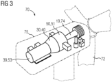
- FIG 3 shows the structure of a first embodiment of a claimed one Wind turbine 70 in a sectioned oblique view.
- the wind turbine 70 includes a multi-blade rotor 72, which is rotatably attached to a nacelle 75 and is connected to a main shaft 74 in a torque-transmitting manner.
- the main shaft 75 serves as an input shaft 19 of a generator transmission 50, which includes a transmission unit 51 and a generator unit 53 with a generator 39.
- the transmission unit 51 and the generator unit 53 are connected to one another in a torque-transmitting manner via a rotor shaft arrangement 30.
- the rotor shaft arrangement 30 includes a curved tooth clutch 40, which ensures angular adjustability 49 between the gear unit 51 and the generator unit 53.
- the rotor shaft arrangement 30 is designed according to at least one of the embodiments outlined above.
Landscapes
- Engineering & Computer Science (AREA)
- General Engineering & Computer Science (AREA)
- Mechanical Engineering (AREA)
- Life Sciences & Earth Sciences (AREA)
- Sustainable Development (AREA)
- Sustainable Energy (AREA)
- Chemical & Material Sciences (AREA)
- Combustion & Propulsion (AREA)
- Wind Motors (AREA)
- Connection Of Motors, Electrical Generators, Mechanical Devices, And The Like (AREA)
Description
- Die Erfindung betrifft eine Windkraftanlage mit einen Mehrblattrotor, der drehbar an einer Gondel angeordnet ist und über eine Hauptwelle mit einem Generatorgetriebe drehmomentübertragend verbunden ist, wobei das Generatorgetriebe eine Getriebeeinheit und eine damit lösbar verbundene Generatoreinheit, die drehmomentübertragend über eine Rotorwellenanordnung mit einer Ausgangswelle und einer Rotorwelle miteinander verbunden sind, umfasst.
- Die Druckschrift
US 2011/272214 A1 offenbart ein Generatorgetriebe, das eine Getriebeeinheit und eine Generatoreinheit umfasst. Eine Sonnenwelle einer Planetenstufe ist an einem generatorseitigen Ende mit einer Verzahnung versehen, die zu einer Kupplung gehört, die eine Verbindung zu einer Rotorwelle herstellt. Die Kupplung ist gewölbt ausgebildet, um einen Versatz zwischen der Sonnenwelle und der Rotorwelle auszugleichen. Radial zu der Verzahnung beabstandet ist die Rotorwelle über Lager gelagert, die auftretende Axialkräfte abstützen können. - Die Internationale Patentanmeldung
WO 02/081280 A1 - Es sind Bogenzahnkupplungen bekannt, bei denen an axialen Enden eines Kupplungszwischenstücks Deckel neben den Bogenverzahnungen angeordnet sind. Durch die Deckel wird eine Abdichtung der Bogenzahnkupplung gegen einen Austritt von Schmierstoff gewährleistet.
- Aus
DE 10 2009 048735 A1 ,DE 11 42 473 B undUS 3 142 972 A sind Wellenkupplungen mit einer Bogenzahnkupplung bekannt. In unterschiedlichen Anwendungen besteht Bedarf an Verbindungen zwischen Wellen, die dazu geeignet ist, hohe Antriebsleistungen zu übertragen und einen Winkelversatz auszugleichen. Gleichzeitig besteht die Zielsetzung, derartige Verbindungen kompakt auszubilden. Dies gilt in besonderem Ausmaß für Windkraftanlagen, in denen ein Getriebe mit einem Generator zu verbinden ist, beispielsweise in einem integrierten Generatorgetriebe. Ebenso wird eine einfache und wirtschaftliche Herstellung solcher Lösungen angestrebt. Der Erfindung liegt die Aufgabenstellung zugrunde, eine Rotorwellenanordnung bereitzustellen, die in zumindest einem der skizzierten Punkte eine Verbesserung bietet. - Die Lösung der Aufgabe erfolgt durch eine Windkraftanlage mit den Merkmalen des Anspruchs 1.
- Bevorzugte Ausgestaltungen der Erfindung sind in den Unteransprüchen definiert.
- Eine Beschreibung eines Merkmals gemeinsam mit einem anderen Merkmal erfolgt nur aus Gründen der vereinfachten Darstellung und soll nicht ausschließen, dass das jeweilige Merkmal auch ohne das andere Merkmal eine Weiterbildung der Erfindung darstellen kann.
- Die Aufgabenstellung wird gelöst durch eine erfindungsgemäße Windkraftanlage, mit einem Mehrblattrotor, der drehbar an einer Gondel angeordnet ist und über eine Hauptwelle mit einem Generatorgetriebe drehmomentübertragend verbunden ist, wobei das Generatorgetriebe eine Getriebeeinheit und eine damit lösbar verbundene Generatoreinheit umfasst, die drehmomentübertragend über eine Rotorwellenanordnung miteinander verbunden sind. Die Rotorwellenanordnung umfasst eine Ausgangswelle für die Getriebeeinheit und eine Rotorwelle für die Generatoreinheit. Die Getriebeeinheit und die Generatoreinheit sind im montierten Zustand mit einer Bogenzahnkupplung drehmomentübertragend miteinander verbunden. Dazu ist die Bogenzahnkupplung mit der Ausgangswelle und der Rotorwelle verbunden. Dabei kann die Ausgangswelle mittels der Bogenzahnkupplung teilweise in der Rotorwelle aufgenommen sein oder die Rotorwelle mittels der Bogenzahnkupplung teilweise in der Ausgangswelle aufgenommen sein. Die Bogenzahnkupplung umfasst auch zumindest ein Stützelement. Das zumindest eine Stützelement ist zu einem axialen Positionieren der Bogenzahnkupplung ausgebildet und ist lösbar befestigt. Das zumindest eine Stützelement ist zu einem Begrenzen einer relativen axialen Beweglichkeit der Bogenzahnkupplung, und damit der Rotorwelle bezüglich der Ausgangswelle, ausgebildet. Das mindestens eine Stützelement weist eine Axialkräfte der Bogenzahnkupplung abstützende Gegenfläche auf, wobei die Gegenfläche bei einem Verkippen der Ausgangswelle relativ zur Rotorwelle an einer korrespondierenden Stützfläche der Ausgangswelle oder der Rotorwelle abgleitbar ausgestaltet ist. Dadurch kann ein Verkippen der Ausgangswelle relativ zur Rotorwelle zugelassen werden, um einen Winkelversatz auszugleichen, wobei gleichzeitig eine Abtragung von Axialkräften über das mindestens eine Stützelement bereitgestellt wird, um eine axiale Relativbewegung des Ausgangswelle zur Rotorwelle zu begrenzen und insbesondere ein axiales Wegwandern der der Ausgangswelle aus einer drehmomentübertragenden Koppelung mit der Rotorwelle zu verhindern. Dementsprechend kann im Betrieb ein axiales Wandern der Rotorwelle auf der Ausgangswelle vermieden werden. Dementsprechend kann die Bogenzahnkupplung entlang einer Axialrichtung, also im Wesentlichen entlang einer Hauptdrehachse der Getriebeeinheit und/oder Generatoreinheit, kompakt ausgebildet werden. Ebenso ist die Rotorwelle damit in einer fliegenden Lagerung aufnehmbar. Das axiale Positionieren der Bogenzahnkupplung gewährleistet eine leichtgängige Beweglichkeit und ermöglicht ein einstellbewegliches, insbesondere winkeleinstellbewegliches, Verhalten zwischen der Ausgangswelle und der Rotorwelle. Das zumindest eine Stützelement ist separat in einfacher Weise herstellbar und erlaubt eine schnelle Montage und Demontage eines Generatorgetriebes mit einer Getriebeeinheit und Generatoreinheit.
- Das zumindest eine Stützelement kann ein erstes Stützelement und/oder ein zweites Stützelement umfassen. Das heißt, die Menge des zumindest einen Stützelements kann genau ein erstes Stützelement, genau ein zweites Stützelement sowie sowohl das erste Stützelement als auch das zweite Stützelement umfassen. Vorzugsweise ist gleichzeitig nur das erste Stützelement und das zweite Stützelement vorgesehen, so dass ein drittes Stützelement und weitere Stützelemente vermieden sind. Insbesondere sind das erste Stützelement und das zweite Stützelement an unterschiedlichen axialen Enden der Bogenzahnkupplung vorgesehen, wobei insbesondere das erste Stützelement und das zweite Stützelement bei der Montage mit einem Bewegungsanteil in axialer Richtung aufeinander zu bewegbar sind, um ein axiales Spiel der Rotorwelle bezüglich der Ausgangswelle, insbesondere im Bereich der Bogenzahnkupplung, zu eliminieren oder auf ein vordefiniertes axiales Spiel zu begrenzen, beispielsweise um eine axiale Spielpassung vorzusehen und/oder eine im laufenden Betrieb zu erwartende axiale Wärmedehnung der Rotorwelle und/oder Ausgangswelle ausgleichen zu können.
- Das erste Stützelement und das zweite Stützelement können auf einem vordefinierten axialen Abstand zueinander vorgesehen sein. Grundsätzlich ist es möglich, dass die axiale Relativlage der Stützelemente relativ zur Rotorwelle und zur Ausgangswelle nicht vordefiniert ist, sondern stattdessen von einem durch die Bogenzahnkupplung auszugleichenden Winkelversatz abhängt. Hierzu kann eine von der Bogenzahnkupplung wegweisende Abstützstelle des jeweiligen Stützelements axial verlagerbar ausgestaltet sein, beispielsweise mit Hilfe einer mit der Rotorwelle oder mit der Ausgangswelle angreifenden Schraubeinrichtung.
- Das mindestens eine Stützelement, insbesondere das erste Stützelement und/oder das zweite Stützelement, weist die bei einem Verkippen der Ausgangswelle relativ zur Rotorwelle zum Ausgleich eines Winkelversatzes mit Hilfe der Bogenzahnkupplung an der Bogenzahnkupplung abgleitbare Gegenfläche auf, die an der korrespondierenden Stützfläche der Ausgangswelle oder der Rotorwelle im Bereich der Bogenzahnkupplung abgleiten kann. Die Bogenzahnkupplung kann einen gebogenen Bereich aufweisen, der in einem inneren Teilbereich mit einer Verzahnung versehen ist und an einem sich an dem inneren Teilbereich anschließenden äußeren Teilbereich durch die Ausgangswelle oder die Rotorwelle die mit dem mindestens einen Stützelement zusammenwirkende Stützfläche ausbildet. Vorzugsweise ist die Stützfläche durch einen unverzahnten gebogenen Bereich der von der Ausgangswelle oder von der Rotorwelle ausgebildeten Kupplungspartner der Bogenzahnkupplung ausgebildet. Beispielsweise sind die Stützfläche und die Gegenfläche als aneinander abgleitbare, insbesondere ringförmige, Kugelkalotten ausgestaltet. Die Stützfläche und die Bogenzahnkupplung können in der Art einer Kugelpfannenlagerung aneinander abgleiten. Dadurch kann ein Verkippen der Ausgangswelle relativ zur Rotorwelle zugelassen werden, um einen Winkelversatz auszugleichen, wobei gleichzeitig die Abtragung von Axialkräften über das mindestens eine Stützelement bereitgestellt wird, um eine axiale Relativbewegung des Ausgangswelle zur Rotorwelle zu begrenzen und insbesondere ein axiales Wegwandern der der Ausgangswelle aus einer drehmomentübertragenden Koppelung mit der Rotorwelle zu verhindern. Vorzugsweise ist die Ausgangswelle mit der Rotorwelle durch das mindestens eine Stützelement axial verliersicher gekoppelt.
- Besondres bevorzugt ist vorgesehen, dass das erste Stützelement und das zweite Stützelement mit den zugeordneten Stützflächen eine Kugelgelenklagerung für die Bogenzahnkupplung ausbilden. Ein axiales Spiel kann dadurch minimiert werden, wobei gleichzeitig ein Verkippen der Ausgangswelle relativ zur Rotorwelle zum Ausgleich eines Winkelversatzes zugelassen ist, aber auftretende Axialkräfte bereits im Bereich der Bogenzahnkupplung an der ausgebildeten Kugelgelenklagerung abgestützt werden können.
- Insbesondere bildet das zumindest eine Stützelement ein zum Ausgleich von im laufenden Betrieb zu erwartenden axialen Wärmedehnungen ausgleichendes axiales Spiel der Ausgangswelle relativ zur Rotorwelle aus. Insbesondere ist zwischen den jeweiligen Stützflächen und der mit der jeweiligen Stützfläche zusammenwirkenden Gegenfläche des jeweiligen Stützelements ein axiales Spiel, insbesondere in der Größenordnung einer Spielpassung, vorgesehen, so dass die Bogenzahnkupplung bei zu erwartenden Wärmedehnungseffekten nicht zwischen dem ersten Stützelement und dem zweiten Stützelement verklemmen kann.
- In einer weiteren Ausführungsform der Rotorwellenanordnung ist ein erstes Stützelement einer der Getriebeeinheit zugewandten Seite der Bogenzahnkupplung angeordnet. Dementsprechend ist die Beweglichkeit zwischen der Rotorwelle und der Ausgangswelle in einfacher Weise einseitig einschränkbar und die Bogenzahnkupplung in einer bestimmungsgemäßen Lage zentrierbar. Alternativ oder ergänzend kann ein zweites Stützelement auf einer der Generatoreinheit zugewandten Seite der Bogenzahnkupplung angeordnet sein. Dadurch ist die Beweglichkeit zwischen der Rotorwelle und der Ausgangswelle in einfacher Weise einseitig einschränkbar. Auch hierdurch wird die Bogenzahnkupplung in einer bestimmungsgemäßen Lage, die eine leichtgängige Winkeleinstellbarkeit zwischen der Rotorwelle und der Ausgangswelle gewährleistet. Eine Kombination des ersten und zweiten Stützelements bietet ein besonders genaues axialen Positionieren der Bogenzahnkupplung. Durch die Stützelemente wird jeweils auch der Winkelversatz zwischen der Rotorwelle und der Ausgangswelle bestimmt. Ein entsprechend genaues axiales Positionieren der Bogenzahnkupplung erlaubt es, deren Verzahnungen in einem optimalen Eingriff zu halten, wodurch eine erhöhte Übertragung von Drehmoment ermöglicht wird und gleichzeitig die Winkeleinstellbarkeit gewährleistet ist. Ferner stützen das erste bzw. zweite Stützelement eine Axiallast ab, die auf die Ausgangswelle einwirkt. Die Axiallast, die auf die Ausgangswelle einwirkt, hängt davon an, welche Steigung eine Schrägverzahnung aufweist, durch die ein Drehmoment in die Ausgangswelle eingeleitet wird.
- Des Weiteren kann in der Rotorwellenanordnung zumindest eine Stützfläche an der Ausgangswelle oder der Rotorwelle ausgebildet sein. Die Stützfläche ist zu einem Abstützen des zumindest einen Stützelements ausgebildet. Die Stützfläche ist ein Bereich der Ausgangswelle bzw. der Rotorwelle, der in puncto Formgebung und Härte zu einem Kontakt mit dem zumindest einen Stützelement geeignet ausgebildet ist. Die Stützfläche kann einstückig mit der Ausgangswelle bzw. der Rotorwelle ausgebildet sein oder als Bereich einer separaten lösbar montierten Komponente. Eine mit der Rotorwelle bzw. Ausgangswelle einstückig ausgebildete Stützfläche ist mit einer erhöhten Genauigkeit herstellbar, was ein präzises axiales Positionieren der Bogenzahnkupplung gewährleistet. Eine an einer separaten Komponente ausgebildete Stützfläche ermöglicht eine kosteneffiziente separate Fertigung und einfache Austauschbarkeit. Ferner kann dabei auch ein besonders leistungsfähiger und kostenintensiver Werkstoff anforderungsgerecht, und dementsprechend wirtschaftlich, eingesetzt werden.
- In einer weiteren Weiterbildung der Rotorwellenanordnung ist die zumindest eine Stützfläche als Schulter im Bereich einer Bogenverzahnung, die zur Bogenzahnkupplung gehört, ausgebildet. Insbesondere kann die Schulter unmittelbar mit der Bogenverzahnung verbunden sein und/oder unmittelbar benachbart zu dieser angeordnet sein. Bogenverzahnungen können einstückig mit der Rotorwelle und/oder der Ausgangswelle ausgebildet sein, was eine besondere Beanspruchbarkeit der Bogenverzahnung gewährleistet. Beim Herstellen der Bogenverzahnung ist eine Schulter, die als Stützfläche geeignet ist, in einfacher Weise in einen vorhandenen Fertigungsprozess integrierbar. Ferner ist die Schulter dazu geeignet, eine belastungsgerechte Lasteinleitung in die Rotorwelle bzw. Ausgangswelle zu gewährleisten. Darüber hinaus sind Schultern an der Rotorwelle bzw. Ausgangswelle in puncto Krümmung anpassbar. Durch eine geeignete Formgebung der Schulter ist die Rotorwellenanordnung an unterschiedliche mechanische Beanspruchungen und unterschiedliche Platzerfordernisse anpassbar. Je länger die Schulter in Axialrichtung ausgebildet ist, umso geringer ist ein Spiel für die Winkeleinstellbarkeit der Bogenzahnkupplung. Die Rotorwellenanordnung ist dementsprechend skalierbar und weist ein breites Einsatzspektrum auf.
- Des Weiteren kann in der Rotorwellenanordnung das zumindest eine lösbar befestigte Stützelement einen zumindest teilweise umlaufend konkav ausgebildeten Abschnitt der Gegenfläche zum axialen Positionieren der Bogenzahnkupplung aufweisen. Der konkav gebildete Abschnitt dient dabei als Gegenstück zur Stützfläche, die diesem gegenüberliegend angeordnet ist. Der zumindest teilweise umlaufende konkave Abschnitt des Stützelements kann mit einem Kugelabschnitt korrespondierend ausgebildet sein, also eine sphärisch ausgebildet sein. Eine derartige Formgebung des Stützelements erlaubt eine leichtgängige Winkeleinstellbarkeit zwischen der Rotorwelle und der Ausgangswelle und gleichzeitig eine vorteilhaft präzise axiale Positionierwirkung. Alternativ oder ergänzend kann die Stützfläche zumindest teilweise umlaufend konvex ausgebildet sein. Insbesondere kann die Stützfläche korrespondierend zum Stützelement konvex ausgebildet sein, so dass eine präzise Führung bei einem sich einstellenden Winkelversatz zwischen der Rotorwelle und der Ausgangswelle gewährleistet ist. Insbesondere kann die Stützfläche mit einem Kugelabschnitt korrespondierend ausgebildet sein, also eine sphärische Form aufweisen. Derartige Formen sind präzise und kosteneffizient herstellbar und bieten eine hohe mechanische Beanspruchbarkeit. Die zumindest teilweise umlaufend konvexe Stützfläche und/oder der zumindest teilweise umlaufend konkave Abschnitt des Stützelements können einen gemeinsamen Mittelpunkt aufweisen, der einer Kippachse der Bogenzahnkupplung entspricht. Dadurch wird insbesondere eine durchgehend leichtgängige Winkeleinstellbarkeit zwischen der Rotorwelle und der Ausgangswelle gewährleistet.
- Ferner kann in der Rotorwellenanordnung die Ausgangswelle und/oder die Rotorwelle als Hohlwelle ausgebildet sein. Eine als Hohlwelle ausgebildete Ausgangswelle und/oder Rotorwelle erlaubt es, die jeweilige andere Welle aufzunehmen und/oder eine weitere Welle, wie beispielsweise ein Pitch-Rohr, durchzuführen. Die Rotorwellenanordnung kann dadurch in Axialrichtung kompakt ausgebildet werden. Ebenso ist ein Rotor in der Generatoreinheit so in Axialrichtung nahe an der Getriebeeinheit platzierbar. Die Rotorwelle kann ferner als separate Komponente ausgebildet werden, die in einfacher Weise mit weiteren Rotorkomponenten verbindbar ist.
- In einer weiteren Ausführungsform der Rotorwellenanordnung ist die Bogenverzahnung an der Ausgangswelle als Außenverzahnung oder als Innenverzahnung ausgebildet. Korrespondierend dazu ist die Bogenverzahnung an der Rotorwelle als Innenverzahnung oder als Außenverzahnung ausgebildet. Eine derart ausgebildete Bogenzahnkupplung bietet in kompakter Weise eine hohe mechanische Beanspruchbarkeit zur Übertragung von Drehmoment und erlaubt eine einfache Montage.
- Darüber hinaus können das zumindest eine Stützelement und die Stützfläche zumindest teilweise aus unterschiedlichen Werkstoffen hergestellt sein. Beispielsweise kann das Stützelement aus einem Gleitlagerwerkstoff hergestellt sein oder mit einem Gleitlagerwerkstoff versehen sein. Dies kann beispielsweise durch eine reibungsvermindernde Beschichtung umgesetzt werden. Bei einer Stützfläche, die beispielsweise aus einem Stahl oder einer Stahllegierung hergestellt ist, ergibt sich eine reduzierte Reibung zwischen der Stützfläche und dem Stützelement, was wiederum zu reduziertem Verschleiß führt.
- Alternativ oder ergänzend können die Stützfläche und/oder das Stützelement wärmebehandelt sein, wodurch die dort vorliegende Reibung weiter reduziert wird. Darüber hinaus kann auch die Stützfläche zumindest teilweise aus einem Gleitlagerwerkstoff hergestellt sein oder mit Gleitlagerwerkstoff versehen sein.
- In einer weiteren Ausführungsform der Rotorwellenanordnung kann die Ausgangswelle als eine Sonnenwelle einer Planetenstufe der Getriebeeinheit ausgebildet sein. Die Rotorwelle kann als Hohlwelle ausgebildet sein. Die Ausgangswelle bildet eine Außenverzahnung für die Bogenzahnkupplung aus, während die Rotorwelle eine Innenverzahnung für die Bogenzahnkupplung ausbildet. Die gesamte Bogenzahnkupplung ist dadurch radial innerhalb der Rotorwelle ausgebildet. Die Rotorwellenanordnung erlaubt es dadurch, die Getriebeeinheit in einfacher Weise mit der Generatoreinheit eines entsprechenden Getriebegenerators zu verbinden. Vorzugsweise sind die Getriebeeinheit ausgangsseitig über die Ausgangswelle und die Generatoreinheit eingangsseitig über die Rotorwelle unmittelbar, das heißt ohne dazwischengeschaltete drehmomentübertragende Bauteile, miteinander gekoppelt. Die Ausgangswelle kann in das Innere der als Hohlwelle ausgestalteten Rotorwelle teilweise eingeschoben sein, so dass die Rotorwelle in radialer Richtung betrachtet einen Teil der Ausgangswelle und insbesondere die gesamte Bogenverzahnung überdecken kann. Insbesondere ist die Rotorwelle unmittelbar mit dem Rotor verbunden auf der Ausgangswelle montierbar. Eine aufwendige Handhabung der gesamten Generatoreinheit, die auch ein Gehäuse umfasst, wird so vermieden. Die Herstellung eines Getriebegenerators mit Getriebeeinheit und Generatoreinheit wird folglich beschleunigt, und ist dadurch kosteneffizient durchführbar. Die Getriebeeinheit ist dazu geeignet, unmittelbar, also frei von einer separaten Kupplung, mit einer Generatoreinheit zu einem Generatorgetriebe verbunden zu werden, so dass diese eine integrierte Einheit bilden. Die Getriebeeinheit umfasst insbesondere zumindest eine Planetenstufe, also eine Getriebestufe die als Planetengetriebe ausgebildet ist. Die zumindest eine Planetenstufe weist eine Welle auf, die mit einer drehbaren Getriebekomponente, also einem Sonnenrad, einem Planetenträger oder einem Hohlrad der Planetenstufe, verbunden ist und als Ausgangswelle der Getriebeeinheit dient. An der Ausgangswelle ist an einem der Generatoreinheit zugewandten Abschnitt eine Bogenverzahnung ausgebildet, die zu einem Bilden einer Bogenzahnkupplung geeignet ist. In einem Bereich der Bogenverzahnung ist zumindest eine Stützfläche ausgebildet, die die einem einstellbeweglichen axialen Positionieren der Bogenverzahnung in der Bogenzahnkupplung geeignet ist. Unter einem einstellbeweglichen axialen Positionieren ist zu verstehen, dass durch die Bogenzahnkupplung ein Winkelversatz zwischen der Ausgangswelle und einer damit im montierten Zustand verbunden Rotorwelle ausgleichbar ist. Die Einstellbeweglichkeit kann dabei eine Winkeleinstellbeweglichkeit sein. Unter dem axialen Positionieren ist ferner ein Halten der Bogenverzahnung in einer Position zu verstehen, die eine leichtgängige Winkeleinstellbarkeit zwischen der Ausgangswelle und der Rotorwelle gewährleistet. Die Getriebeeinheit ist dazu mit einer Rotorwellenanordnung gemäß zumindest einer der oben skizzierten Ausführungsformen kombiniert ausgebildet.
- Bei einer Ausgangswelle, die als Sonnenwelle einer Planetenstufe ausgebildet ist, wird durch die Rotorwellenanordnung für die Ausgangswelle eine vorteilhafte Winkeleinstellbarkeit erzielt. Dementsprechend ist eine sich selbsttätig einstellende vorteilhafte Ausrichtung der Sonnenwelle erzielbar, bei der eine gleichmäßige Lastverteilung Planetenräder erreicht wird, die mit der Sonnenwelle kämmen. Dadurch wird Verschleiß in der Getriebeeinheit minimiert.
- Vorzugsweise weist die Getriebeeinheit drei oder mehr hintereinandergeschaltete Planetenstufen auf. Eine Hintereinanderschaltung ist hierbei eine drehmomentübertragende Verbindung zwischen den Planetenstufen, durch die eine in die Getriebeeinheit zugeführte Antriebsleistung unverzweigt durchgeführt wird. Derartige Hintereinanderschaltungen sind unter anderem in der Internationalen Anmeldung
WO 2020/001942 A1 offenbart. - Die Getriebeeinheit bietet ein hohes Maß an mechanischer Leistungsfähigkeit bei gleichzeitig kompakter Bauform, reduziertem Gewicht und hoher Wirtschaftlichkeit.
- Darüber hinaus wird die zugrundeliegende Aufgabenstellung durch ein nicht beanspruchtes Computerprogrammprodukt gelöst, das zu einem Simulieren eines Betriebsverhaltens einer Rotorwellenanordnung ausgebildet ist. Dazu kann das Computerprogrammprodukt Daten zur Kinematik der Ausgangswelle, der Rotorwelle und der Bogenzahnkupplung umfassen. Ferner kann das Computerprogrammprodukt Simulationsroutinen umfassen, die dazu ausgebildet sind, basierend auf Angaben zu Abmessungen der Rotorwelle, der Ausgangswelle und/oder der Bogenzahnkupplung ein Schwingungsverhalten der Rotorwellenanordnung zu ermitteln. Das Computerprogrammprodukt kann auch eine Datenschnittstelle aufweisen, über die Betriebsparameter, wie beispielsweise eine Drehzahl der Ausgangswelle, ein über die Ausgangswelle transportiertes Drehmoment, oder Ausrichtung der Ausgangswelle vorgebbar sind. Ebenso kann das Computerprogrammprodukt auch eine Datenschnittstelle zum Ausgeben von Simulationsergebnissen aufweisen. Erfindungsgemäß ist die Rotorwellenanordnung, deren Betriebsverhalten mittels des Computerprogrammprodukts simulierbar ist, gemäß mindestens einer der oben skizzierten Ausführungsformen ausgebildet. Das Computerprogrammprodukt kann dazu beispielsweise als sogenannter Digitaler Zwilling ausgebildet sein. Derartige Digitale Zwillinge sind unter anderem in der Offenlegungsschrift
US 2017/0286572 A1 dargestellt. - Die Erfindung wird im Folgenden anhand einzelner Ausführungsformen in Figuren näher erläutert. Die Figuren sind insoweit in gegenseitiger Ergänzung zu lesen, dass gleiche Bezugszeichen in unterschiedlichen Figuren die gleiche technische Bedeutung haben. Die Merkmale der einzelnen Ausführungsformen sind untereinander auch kombinierbar. Ferner sind die in den Figuren gezeigten Ausführungsformen mit den oben skizzierten Merkmalen kombinierbar. Es zeigen im Einzelnen:
- FIG 1
- schematisch eine erste Ausführungsform einer
- FIG 2
- Rotorwellenanordnung im Längsschnitt; einen schematischen Aufbau einer ersten Ausführungsform eines Generatorgetriebes;
- FIG 3
- eine erste Ausführungsform der beanspruchten Windkraftanlage in einer geschnittenen Schrägansicht.
- In
FIG 1 ist schematisch ein Längsschnitt einer ersten Ausführungsform einer Rotorwellenanordnung 30 dargestellt, die eine Ausgangswelle 10 umfasst, die als Hohlwelle 11 ausgebildet ist, und eine Rotorwelle 20, die auch als Hohlwelle 21 ausgebildet ist und in Rotorwellenlagern 28 an einem nicht näher dargestellten Gehäuse 34 drehbar aufgenommen ist. Über die Ausgangswelle 10 wird bezogen auf eine Hauptdrehachse 15 ein Drehmoment 25 zugeführt, das auf die Rotorwelle 20 zu übertragen ist. Die Ausgangswelle 10 ist einer nicht näher dargestellten Getriebeeinheit 51 auf einer Getriebeseite 31 zugeordnet und die Rotorwelle 20 einer nicht näher gezeigten Generatoreinheit 53 auf einer Generatorseite 33. Die Ausgangswelle 10 ist an einem der Generatorseite 33 zugewandten Ende mit einer Bogenverzahnung 12 versehen, die als Außenverzahnung 13 ausgebildet ist. Die Rotorwelle 20 ist korrespondierend mit einer Bogenverzahnung 22 versehen, die als Innenverzahnung 23 ausgebildet ist und mit der Bogenverzahnung 12 der Rotorwelle 10 kämmt. Die Bogenverzahnungen 12, 22 an der Ausgangswelle 10 und der Rotorwelle 20 gehören damit zu einer Bogenzahnkupplung 40, die um einen Drehpunkt 45 einen Winkelversatz zwischen der Ausgangswelle 10 und der Rotorwelle 20 erlaubt. Der Winkelversatz kann sich dabei jeweils für die Ausgangswelle 10 und die Rotorwelle 20 bezogen auf die Hauptdrehachse 15 einstellen. Dadurch wird eine Winkeleinstellbeweglichkeit 49 erzielt, die inFIG 1 durch den entsprechend bezeichneten Doppelpfeil versinnbildlicht ist. In einem optimal ausgerichteten Zustand, wie inFIG 1 gezeigt, sind ein Scheitelpunkt 17 der Bogenverzahnung 12 an der Ausgangswelle 10 und ein Scheitelpunkt 27 der Bogenverzahnung 22 an der Rotorwelle 20 in eine Radialrichtung 37 im Wesentlichen fluchtend positioniert. - Die Bogenzahnkupplung 40 umfasst auch Stützelemente 42, die umlaufend ausgebildet sind und im Bereich der Bogenverzahnungen 12, 22 angeordnet sind. Im montierten Zustand sind die Stützelemente 42 mit Sicherungsringen 48 befestigt. Die Stützelemente 42 sind lösbar montiert, wobei eine erstes Stützelement 44, bezogen auf die Bogenzahnkupplung 40, auf der Getriebeseite 31 angeordnet ist und eine zweites Stützelement 46 auf der Generatorseite 33. Durch das Anordnen der Stützelemente 42, 44, 46 in einem Bereich 41 der Bogenverzahnungen 12, 22 wird die Winkeleinstellbeweglichkeit 49, also der maximal erreichbare Winkelversatz, bestimmt. Die Stützelemente 42, 44, 46 verfügen jeweils über eine Gegenfläche 43, die umlaufend und im Wesentlichen konkav ausgebildet ist, und einer Stützfläche 16 an der Ausgangwelle 10 gegenüberliegend angeordnet ist. Die Stützflächen 16 sind einstückig mit der Ausgangswelle 10 ausgebildet und gehören jeweils zu einer Schulter 18, die auch einstückig mit der Ausgangswelle 10 ausgebildet ist. Die Stützflächen 16 sind jeweils im Wesentlichen konvex ausgebildet, wobei die Form der Stützflächen 16 mit der konkaven Form der Gegenflächen 43 an der Rotorwelle 20 korrespondieren. Die Stützflächen 16 und die Gegenflächen 43 sind sphärisch ausgebildet und weisen den Drehpunkt 45 der Winkeleinstellbarkeit 49 als Mittelpunkt auf. Eine derartige sphärische Form der Bogenzahnkupplung 40 bietet für die Winkeleinstellbarkeit 49 eine besondere Leichtgängigkeit. Fernern ist zumindest eines der Stützelemente 42, 44, 46 im Bereich der Gegenfläche 43 aus einem anderen Werkstoff als eine korrespondierende Stützfläche 16 an der Ausgangswelle 10 hergestellt sein. Zumindest eines der Stützelemente 42, 44, 46 ist aus einem Gleitlagerwerkstoff hergestellt, durch die Reibung zwischen der entsprechenden Stützfläche 16 und der Stützelement 42, 44, 46 minimiert wird. Des Weiteren wird die Bogenzahnkupplung 40, also die Bogenverzahnungen 12, 22 an der Ausgangswelle 10 und der Rotorwelle 20 entlang einer Axialrichtung 35 durch die Stützelemente 42, 44, 46 positioniert. Das axiale Positionieren durch die Stützelemente 42, 44, 46 gewährleistet, dass die Bogenverzahnungen 12, 22 in der Breite, also ihrer Abmessung entlang der Axialrichtung 35, minimiert wird. Dadurch ist gewährleistet, dass eine maximale Überdeckung der Bogenverzahnungen 12, 22 im Eingriff, also beim Kämmen, vorliegt. Dementsprechend genügt eine minimale Breite für die Bogenverzahnungen 12, 22. Ferner ist in der als Hohlwelle 11 ausgebildeten Ausgangswelle 10 ein Pitchrohr 36 drehbar aufgenommen. Eine generatorseitige Stirnseite 14 der Ausgangswelle 10 liegt entlang der Axialrichtung 35 im Bereich der Rotorwelle 20. Die Ausgangswelle 10 ist damit auf der Generatorseite 33 lagerfrei angeordnet, das wiederum die Anzahl an Bauteilen in der Rotorwellenanordnung 30 reduziert und deren Montage vereinfacht. Die Rotorwellenanordnung 30 in
FIG 1 ist ferner in einem Computerprogrammprodukt 80 nachgebildet, das dazu ausgebildet ist, das Betriebsverhalten der Rotorwellenanordnung 30 zu simulieren. - Eine erste Ausführungsform eines Generatorgetriebes 50 ist in
FIG 2 in ihrem Aufbau schematisch abgebildet. Das Generatorgetriebe 50 umfasst eine Getriebeeinheit 51, die lösbar mit einer Generatoreinheit 53 verbunden ist. Die Getriebeeinheit 51 umfasst drei Planetenstufen 55, die hintereinandergeschaltet sind, so dass ein Drehmoment 25, das über eine Eingangswelle 19 zugeführt wird, zwischen den Planetenstufen 55 unverzweigt zur Generatoreinheit 53 transportiert wird. Die Eingangswelle 19 ist um eine Hauptdrehachse 15 des Generatorgetriebes 50 drehbar und ist dabei als eine Hauptwelle 74 einer nicht näher gezeigten Windkraftanlage 70 ausgebildet. Die erste, zweite und dritte Planetenstufe 55.1, 55.2, 55.3 weisen jeweils ein Hohlrad 57, einen Planetenträger 56 mit mindestens einem Planetenrad 58, und ein Sonnenrad 59 auf. Die Hohlräder 57 sind in einem Gehäuse 34 befestigt, das die Getriebeeinheit 51 zumindest teilweise umschließt. Das zugeführte Drehmoment 25 wird dementsprechend von der Getriebeseite 31 in Richtung der Generatorseite 33 transportiert, wobei eine Ausgangswelle 10 der Getriebeeinheit 51 mit einem Generator 39 auf der Generatoreinheit 53 drehmomentübertragend verbunden ist. Die Ausgangswelle 10 ist als eine Sonnenwelle 47 einer der Planetenstufen 55, insbesondere der dritten Planetenstufe 55.3, ausgebildet. Ferner gehört die Ausgangswelle 10 zu einer Rotorwellenanordnung 30, die auch eine Rotorwelle 20 umfasst, wobei die Ausgangswelle 10 und die Rotorwelle 20 mittels einer Bogenzahnkupplung 40 miteinander verbunden sind. Die Rotorwellenanordnung 30 ist dabei gemäß einer der oben beschriebenen Ausführungsformen ausgebildet. Eine Getriebeeinheit 51 mit drei Planetenstufen 55, 55.1, 55.2, 55.3, die über eine als Ausgangswelle 10 dienende Sonnenwelle 47 unmittelbar mit einem Generator 39 verbunden ist, bietet ein besonderes Maß an Leistungsfähigkeit, Wirtschaftlichkeit und Zuverlässigkeit für eine Windkraftanlage 70. -
FIG 3 zeigt den Aufbau einer ersten Ausführungsform einer beanspruchten Windkraftanlage 70 in einer geschnittenen Schrägansicht. Die Windkraftanlage 70 umfasst einen Mehrblattrotor 72, der drehbar an einer Gondel 75 angebracht ist und drehmomentübertragend mit einer Hauptwelle 74 verbunden ist. Die Hauptwelle 75 dient als Eingangswelle 19 eines Generatorgetriebes 50, das eine Getriebeeinheit 51 und eine Generatoreinheit 53 mit einem Generator 39 umfasst. Die Getriebeeinheit 51 und die Generatoreinheit 53 sind über eine Rotorwellenanordnung 30 drehmomentübertragend miteinander verbunden. Die Rotorwellenanordnung 30 umfasst eine Bogenzahnkupplung 40, durch die eine Winkeleinstellbarkeit 49 zwischen der Getriebeeinheit 51 und der Generatoreinheit 53 gewährleistet ist. Die Rotorwellenanordnung 30 ist dabei gemäß zumindest einer der oben skizzierten Ausführungsformen ausgebildet.
Claims (12)
- Windkraftanlage (70), umfassend einen Mehrblattrotor (72), der drehbar an einer Gondel (75) angeordnet ist und über eine Hauptwelle (74) mit einem Generatorgetriebe (50) drehmomentübertragend verbunden ist, wobei das Generatorgetriebe eine Getriebeeinheit (51) und eine damit lösbar verbundene Generatoreinheit (53), die drehmomentübertragend über eine Rotorwellenanordnung (30) miteinander verbunden sind, umfasst und die Rotorwellenanordnung (30) eine Ausgangswelle (10) für die Getriebeeinheit (51) und eine Rotorwelle (20) für die Generatoreinheit (53), die über eine Bogenzahnkupplung (40) miteinander verbunden sind, umfasst, dadurch gekennzeichnet, dass die Bogenzahnkupplung (40) zumindest ein lösbar befestigtes Stützelement (42,44,46) zu einem axialen Positionieren der Bogenzahnkupplung (40) aufweist, wobei das mindestens eine Stützelement (42,44,46) eine Axialkräfte der Bogenzahnkupplung (40) abstützende Gegenfläche aufweist, wobei die Gegenfläche bei einem Verkippen der Ausgangswelle (10) relativ zur Rotorwelle an einer korrespondierenden Stützfläche (16) der Ausgangswelle (10) oder der Rotorwelle (20) abgleitbar ausgestaltet ist.
- Windkraftanlage (70) nach Anspruch 1, dadurch gekennzeichnet, dass ein erstes Stützelement (44) des zumindest einen Stützelements (42,44,46) auf einer der Getriebeeinheit (51) zugewandten Seite (31) der Bogenzahnkupplung (40) angeordnet ist.
- Windkraftanlage (70) nach Anspruch 1 oder 2, da-durch gekennzeichnet, dass ein zweites Stützelement (46) des zumindest einen Stützelements (42,44,46) auf einer der Generatoreinheit (53) zugewandten Seite (33) der Bogenzahnkupplung (40) angeordnet ist.
- Windkraftanlage (70) nach der Kombination der Ansprüche 2 und 3, dadurch gekennzeichnet, dass das erste Stützelement (44) und das zweite Stützelement (46) mit den zugeordneten Stützflächen (16) eine Kugelgelenklagerung für die Bogenzahnkupplung (40) ausbilden.
- Windkraftanlage (70) nach einem der Ansprüche 1 bis 4, dadurch gekennzeichnet, dass das zumindest eine Stützelement (42,44,46) ein zum Ausgleich von im laufenden Betrieb zu erwartenden axialen Wärmedehnungen ausgleichendes axiales Spiel der Ausgangswelle (10) relativ zur Rotorwelle (20) ausbildet.
- Windkraftanlage (70) nach einem der Ansprüche 1 bis 5, dadurch gekennzeichnet, dass die Ausgangswelle (10) mit der Rotorwelle (20) durch das mindestens eine Stützelement (42, 44, 46) verliersicher gekoppelt ist.
- Windkraftanlage (70) nach einem der Ansprüche 1 bis 6, dadurch gekennzeichnet, dass die zumindest eine Stützfläche (16) als Schulter (18) im Bereich einer Bogenverzahnung (12,22) ausgebildet ist, wobei insbesondere die Schulter (18) unmittelbar mit der Bogenverzahnung (12, 22) verbunden ist und/oder unmittelbar benachbart zu der Bogenverzahnung (12, 22) angeordnet ist.
- Windkraftanlage (70) nach einem der Ansprüche 1 bis 7, dadurch gekennzeichnet, dass die zumindest eine Stützfläche (16) zumindest teilweise umlaufend konvex, insbesondere als ringförmige Kugelkalotte, ausgebildet ist.
- Windkraftanlage (70) nach einem der Ansprüche 1 bis 8, dadurch gekennzeichnet, dass das das zumindest eine Stützelement (42,44,46) und die Stützfläche (16) zumindest teilweise aus unterschiedlichen Werkstoffen hergestellt sind.
- Windkraftanlage (70) nach einem der Ansprüche 1 bis 9, dadurch gekennzeichnet, dass das zumindest eine lösbar befestigte Stützelement (42,44,46) einen zumindest teilweise umlaufend konkav ausgebildeten Abschnitt der Gegenfläche zum axialen Positionieren der Bogenzahnkupplung (40) aufweist.
- Windkraftanlage (70) nach einem der Ansprüche 1 bis 10, dadurch gekennzeichnet, dass die Ausgangswelle (10) als eine Sonnenwelle (47) einer Planetenstufe (55,55.1,55.2,55.3) der Getriebeeinheit (51) und die die Rotorwelle (20) als Hohlwelle (11,21) ausgebildet sind, wobei die Ausgangswelle (10) eine Außenverzahnung (13) für die Bogenzahnkupplung (40) und die Rotorwelle (20) eine Innenverzahnung (23) für die Bogenzahnkupplung (40) ausbildet, wobei die gesamte Bogenzahnkupplung (40) radial innerhalb der Rotorwelle (20) ausgebildet ist.
- Windkraftanlage (70) nach einem der Ansprüche 1 bis 11 dadurch gekennzeichnet, dass die Getriebeeinheit (51) zumindest eine Planetenstufe (55,55.1,55.2,55.3) mit der Ausgangswelle (10) umfasst, an der die Bogenverzahnung (12,22) ausgebildet ist, wobei im Bereich der Bogenverzahnung (12,22) zumindest eine Stützfläche (16) zu einem winkelbeweglichen axialen Positionieren der Bogenverzahnung (12,22) in einer Bogenzahnkupplung (40) ausgebildet ist.
Applications Claiming Priority (2)
| Application Number | Priority Date | Filing Date | Title |
|---|---|---|---|
| EP20186499.8A EP3940228A1 (de) | 2020-07-17 | 2020-07-17 | Einstellbewegliche rotorwellenanordnung, getriebeeinheit, generatorgetriebe und windkraftanlage |
| PCT/EP2021/069460 WO2022013219A1 (de) | 2020-07-17 | 2021-07-13 | Einstellbewegliche rotorwellenanordnung, datenagglomerat, generatorgetriebe und windkraftanlage |
Publications (2)
| Publication Number | Publication Date |
|---|---|
| EP4182558A1 EP4182558A1 (de) | 2023-05-24 |
| EP4182558B1 true EP4182558B1 (de) | 2024-04-03 |
Family
ID=71670137
Family Applications (2)
| Application Number | Title | Priority Date | Filing Date |
|---|---|---|---|
| EP20186499.8A Withdrawn EP3940228A1 (de) | 2020-07-17 | 2020-07-17 | Einstellbewegliche rotorwellenanordnung, getriebeeinheit, generatorgetriebe und windkraftanlage |
| EP21740569.5A Active EP4182558B1 (de) | 2020-07-17 | 2021-07-13 | Windkraftanlage mit generatorgetriebe und rotorwellenanordnung |
Family Applications Before (1)
| Application Number | Title | Priority Date | Filing Date |
|---|---|---|---|
| EP20186499.8A Withdrawn EP3940228A1 (de) | 2020-07-17 | 2020-07-17 | Einstellbewegliche rotorwellenanordnung, getriebeeinheit, generatorgetriebe und windkraftanlage |
Country Status (5)
| Country | Link |
|---|---|
| US (1) | US12092078B2 (de) |
| EP (2) | EP3940228A1 (de) |
| CN (1) | CN116134232A (de) |
| ES (1) | ES2985720T3 (de) |
| WO (1) | WO2022013219A1 (de) |
Citations (4)
| Publication number | Priority date | Publication date | Assignee | Title |
|---|---|---|---|---|
| EP2216547A2 (de) | 2009-01-16 | 2010-08-11 | General Electric Company | Kompakter Zahnradantriebsstrang für Windturbine |
| EP2273112A2 (de) | 2009-06-30 | 2011-01-12 | General Electric Company | Triebstrang für einen Windturbinengenerator |
| EP2933483A1 (de) | 2014-04-15 | 2015-10-21 | Siemens Aktiengesellschaft | Antriebssystem einer Windkraftanlage |
| DE102016213476A1 (de) | 2016-07-22 | 2018-01-25 | Zf Friedrichshafen Ag | Passverzahnung mit Axialsicherung |
Family Cites Families (13)
| Publication number | Priority date | Publication date | Assignee | Title |
|---|---|---|---|---|
| DE1142473B (de) * | 1955-07-25 | 1963-01-17 | Buckau Wolf Maschf R | Wellenkupplung fuer achsparallele und winklige Wellenverlagerungen |
| US3142972A (en) * | 1962-09-10 | 1964-08-04 | Bunting Brass & Bronze Co | Misalignment coupling |
| DE3722097C1 (de) * | 1987-07-03 | 1988-08-11 | Netzsch Mohnopumpen Gmbh | Drehgelenkkupplung |
| DE10117749A1 (de) | 2001-04-09 | 2002-11-21 | Siemens Ag | Fahrzeugantrieb mit Bogenzahnkupplung |
| NO327565B1 (no) * | 2008-01-14 | 2009-08-17 | Angle Wind As | Anordning ved vindmolle |
| DE102009008340A1 (de) * | 2008-12-19 | 2010-06-24 | Robert Bosch Gmbh | Strömungskraftanlage |
| DE102009048735A1 (de) * | 2009-10-08 | 2011-04-14 | Robert Bosch Gmbh | Antriebsstrang und Windkraftanlage |
| ES2730717T5 (en) | 2010-05-06 | 2025-11-07 | The Switch Eng Oy | An electromechanical device |
| AU2012294255B2 (en) | 2011-08-10 | 2016-03-17 | Precision Planting Llc | Yield monitoring apparatus, systems, and methods |
| US20170286572A1 (en) | 2016-03-31 | 2017-10-05 | General Electric Company | Digital twin of twinned physical system |
| EP3587863A1 (de) | 2018-06-25 | 2020-01-01 | Flender GmbH | Planetengetriebe, antriebsstrang, windkraftanlage und industrie-applikation |
| US10363705B1 (en) * | 2018-10-12 | 2019-07-30 | Capital One Services, Llc | Determining a printing anomaly related to a 3D printed object |
| US11267191B2 (en) * | 2019-05-07 | 2022-03-08 | GM Global Technology Operations LLC | Methods for composite part manufacturing |
-
2020
- 2020-07-17 EP EP20186499.8A patent/EP3940228A1/de not_active Withdrawn
-
2021
- 2021-07-13 US US18/016,228 patent/US12092078B2/en active Active
- 2021-07-13 EP EP21740569.5A patent/EP4182558B1/de active Active
- 2021-07-13 ES ES21740569T patent/ES2985720T3/es active Active
- 2021-07-13 CN CN202180060783.0A patent/CN116134232A/zh active Pending
- 2021-07-13 WO PCT/EP2021/069460 patent/WO2022013219A1/de not_active Ceased
Patent Citations (4)
| Publication number | Priority date | Publication date | Assignee | Title |
|---|---|---|---|---|
| EP2216547A2 (de) | 2009-01-16 | 2010-08-11 | General Electric Company | Kompakter Zahnradantriebsstrang für Windturbine |
| EP2273112A2 (de) | 2009-06-30 | 2011-01-12 | General Electric Company | Triebstrang für einen Windturbinengenerator |
| EP2933483A1 (de) | 2014-04-15 | 2015-10-21 | Siemens Aktiengesellschaft | Antriebssystem einer Windkraftanlage |
| DE102016213476A1 (de) | 2016-07-22 | 2018-01-25 | Zf Friedrichshafen Ag | Passverzahnung mit Axialsicherung |
Non-Patent Citations (2)
| Title |
|---|
| DUDLEY DARLE W.: "When Splines need Stress Control", PRODUCT ENGINEERING, 1 January 1957 (1957-01-01), pages 316 - 319, XP093253801 |
| MARANO DAVIDE ET AL: "Misalignment Compensation Spline Design", AGMA TECHNICAL PAPER, 1 October 2019 (2019-10-01), pages 1 - 17, XP093253800 |
Also Published As
| Publication number | Publication date |
|---|---|
| WO2022013219A1 (de) | 2022-01-20 |
| US20230340943A1 (en) | 2023-10-26 |
| EP4182558A1 (de) | 2023-05-24 |
| ES2985720T3 (es) | 2024-11-07 |
| CN116134232A (zh) | 2023-05-16 |
| EP3940228A1 (de) | 2022-01-19 |
| US12092078B2 (en) | 2024-09-17 |
Similar Documents
| Publication | Publication Date | Title |
|---|---|---|
| EP3351830B2 (de) | Planetengetriebe mit verbesserter planetenträgerlagerung | |
| EP3489549B1 (de) | Planetengetriebe und gleitlagerstift für ein planetengetriebe | |
| DE102018104685B4 (de) | Antriebsvorrichtung mit einem Elektromotor und einem Getriebe | |
| EP3489550A1 (de) | Planetengetriebe und gleitlagerstift für ein planetengetriebe | |
| WO2009030189A2 (de) | Rotorlagerung für eine windenergieanlage | |
| EP0459352A1 (de) | Verzweigungsgetriebe | |
| WO2022179845A1 (de) | Sonnenrad für ein planetenradgetriebe | |
| DE10017548B4 (de) | Generatorgetriebe | |
| EP1559928B1 (de) | Umlaufgetriebe für eine Windenergieanlage | |
| DE10302192B4 (de) | Planetengetriebe mit einer Ausgleichskupplung | |
| EP4182558B1 (de) | Windkraftanlage mit generatorgetriebe und rotorwellenanordnung | |
| EP2255104A1 (de) | Getriebe | |
| EP3828442A1 (de) | Getriebe mit einem flexiblen zahnrad | |
| EP0719964B1 (de) | Stirnräderplanetengetriebe | |
| EP0025901A2 (de) | Elastische Kupplung | |
| DE102011103495A1 (de) | Kupplungswelle,Aktor,Nockenwellenverstellgetriebe und Nockenwellensteller | |
| EP3230622B1 (de) | Gelenkig gelagerter planetenschaft | |
| DE102014008377A1 (de) | Radflansch-Gelenkgehäuseanordnung für eine Seitenwelle eines Fahrzeugs | |
| DE2361614A1 (de) | Zahnrad-baugruppe | |
| EP3816478A1 (de) | Koaxialgetriebe mit axial beweglichen zähnen | |
| EP1886047B1 (de) | Differentialanordnung mit montageöffnungen | |
| EP1939478B1 (de) | Schaltkupplung für Schalt-/Synchronisiereinrichtung, insbesondere für Schaltgetriebe eines Kraftfahrzeugs | |
| DE102015017188B4 (de) | Spannungswellengetriebe | |
| DE10063467B4 (de) | Verstellvorrichtung | |
| EP4653716A1 (de) | Welle-nabe-verbindung mit axialsicherung |
Legal Events
| Date | Code | Title | Description |
|---|---|---|---|
| STAA | Information on the status of an ep patent application or granted ep patent |
Free format text: STATUS: UNKNOWN |
|
| STAA | Information on the status of an ep patent application or granted ep patent |
Free format text: STATUS: THE INTERNATIONAL PUBLICATION HAS BEEN MADE |
|
| PUAI | Public reference made under article 153(3) epc to a published international application that has entered the european phase |
Free format text: ORIGINAL CODE: 0009012 |
|
| STAA | Information on the status of an ep patent application or granted ep patent |
Free format text: STATUS: REQUEST FOR EXAMINATION WAS MADE |
|
| 17P | Request for examination filed |
Effective date: 20230213 |
|
| AK | Designated contracting states |
Kind code of ref document: A1 Designated state(s): AL AT BE BG CH CY CZ DE DK EE ES FI FR GB GR HR HU IE IS IT LI LT LU LV MC MK MT NL NO PL PT RO RS SE SI SK SM TR |
|
| DAV | Request for validation of the european patent (deleted) | ||
| DAX | Request for extension of the european patent (deleted) | ||
| GRAP | Despatch of communication of intention to grant a patent |
Free format text: ORIGINAL CODE: EPIDOSNIGR1 |
|
| STAA | Information on the status of an ep patent application or granted ep patent |
Free format text: STATUS: GRANT OF PATENT IS INTENDED |
|
| INTG | Intention to grant announced |
Effective date: 20240124 |
|
| GRAS | Grant fee paid |
Free format text: ORIGINAL CODE: EPIDOSNIGR3 |
|
| GRAA | (expected) grant |
Free format text: ORIGINAL CODE: 0009210 |
|
| STAA | Information on the status of an ep patent application or granted ep patent |
Free format text: STATUS: THE PATENT HAS BEEN GRANTED |
|
| AK | Designated contracting states |
Kind code of ref document: B1 Designated state(s): AL AT BE BG CH CY CZ DE DK EE ES FI FR GB GR HR HU IE IS IT LI LT LU LV MC MK MT NL NO PL PT RO RS SE SI SK SM TR |
|
| REG | Reference to a national code |
Ref country code: CH Ref legal event code: EP |
|
| REG | Reference to a national code |
Ref country code: DE Ref legal event code: R096 Ref document number: 502021003229 Country of ref document: DE |
|
| REG | Reference to a national code |
Ref country code: IE Ref legal event code: FG4D Free format text: LANGUAGE OF EP DOCUMENT: GERMAN |
|
| REG | Reference to a national code |
Ref country code: LT Ref legal event code: MG9D |
|
| REG | Reference to a national code |
Ref country code: NL Ref legal event code: MP Effective date: 20240403 |
|
| PG25 | Lapsed in a contracting state [announced via postgrant information from national office to epo] |
Ref country code: NL Free format text: LAPSE BECAUSE OF FAILURE TO SUBMIT A TRANSLATION OF THE DESCRIPTION OR TO PAY THE FEE WITHIN THE PRESCRIBED TIME-LIMIT Effective date: 20240403 |
|
| PG25 | Lapsed in a contracting state [announced via postgrant information from national office to epo] |
Ref country code: NL Free format text: LAPSE BECAUSE OF FAILURE TO SUBMIT A TRANSLATION OF THE DESCRIPTION OR TO PAY THE FEE WITHIN THE PRESCRIBED TIME-LIMIT Effective date: 20240403 |
|
| PG25 | Lapsed in a contracting state [announced via postgrant information from national office to epo] |
Ref country code: IS Free format text: LAPSE BECAUSE OF FAILURE TO SUBMIT A TRANSLATION OF THE DESCRIPTION OR TO PAY THE FEE WITHIN THE PRESCRIBED TIME-LIMIT Effective date: 20240803 |
|
| PG25 | Lapsed in a contracting state [announced via postgrant information from national office to epo] |
Ref country code: BG Free format text: LAPSE BECAUSE OF FAILURE TO SUBMIT A TRANSLATION OF THE DESCRIPTION OR TO PAY THE FEE WITHIN THE PRESCRIBED TIME-LIMIT Effective date: 20240403 |
|
| PG25 | Lapsed in a contracting state [announced via postgrant information from national office to epo] |
Ref country code: HR Free format text: LAPSE BECAUSE OF FAILURE TO SUBMIT A TRANSLATION OF THE DESCRIPTION OR TO PAY THE FEE WITHIN THE PRESCRIBED TIME-LIMIT Effective date: 20240403 Ref country code: FI Free format text: LAPSE BECAUSE OF FAILURE TO SUBMIT A TRANSLATION OF THE DESCRIPTION OR TO PAY THE FEE WITHIN THE PRESCRIBED TIME-LIMIT Effective date: 20240403 |
|
| PG25 | Lapsed in a contracting state [announced via postgrant information from national office to epo] |
Ref country code: GR Free format text: LAPSE BECAUSE OF FAILURE TO SUBMIT A TRANSLATION OF THE DESCRIPTION OR TO PAY THE FEE WITHIN THE PRESCRIBED TIME-LIMIT Effective date: 20240704 |
|
| PG25 | Lapsed in a contracting state [announced via postgrant information from national office to epo] |
Ref country code: PT Free format text: LAPSE BECAUSE OF FAILURE TO SUBMIT A TRANSLATION OF THE DESCRIPTION OR TO PAY THE FEE WITHIN THE PRESCRIBED TIME-LIMIT Effective date: 20240805 |
|
| PG25 | Lapsed in a contracting state [announced via postgrant information from national office to epo] |
Ref country code: CZ Free format text: LAPSE BECAUSE OF FAILURE TO SUBMIT A TRANSLATION OF THE DESCRIPTION OR TO PAY THE FEE WITHIN THE PRESCRIBED TIME-LIMIT Effective date: 20240403 |
|
| PG25 | Lapsed in a contracting state [announced via postgrant information from national office to epo] |
Ref country code: PL Free format text: LAPSE BECAUSE OF FAILURE TO SUBMIT A TRANSLATION OF THE DESCRIPTION OR TO PAY THE FEE WITHIN THE PRESCRIBED TIME-LIMIT Effective date: 20240403 |
|
| PG25 | Lapsed in a contracting state [announced via postgrant information from national office to epo] |
Ref country code: LV Free format text: LAPSE BECAUSE OF FAILURE TO SUBMIT A TRANSLATION OF THE DESCRIPTION OR TO PAY THE FEE WITHIN THE PRESCRIBED TIME-LIMIT Effective date: 20240403 |
|
| PG25 | Lapsed in a contracting state [announced via postgrant information from national office to epo] |
Ref country code: PT Free format text: LAPSE BECAUSE OF FAILURE TO SUBMIT A TRANSLATION OF THE DESCRIPTION OR TO PAY THE FEE WITHIN THE PRESCRIBED TIME-LIMIT Effective date: 20240805 Ref country code: PL Free format text: LAPSE BECAUSE OF FAILURE TO SUBMIT A TRANSLATION OF THE DESCRIPTION OR TO PAY THE FEE WITHIN THE PRESCRIBED TIME-LIMIT Effective date: 20240403 Ref country code: NO Free format text: LAPSE BECAUSE OF FAILURE TO SUBMIT A TRANSLATION OF THE DESCRIPTION OR TO PAY THE FEE WITHIN THE PRESCRIBED TIME-LIMIT Effective date: 20240703 Ref country code: LV Free format text: LAPSE BECAUSE OF FAILURE TO SUBMIT A TRANSLATION OF THE DESCRIPTION OR TO PAY THE FEE WITHIN THE PRESCRIBED TIME-LIMIT Effective date: 20240403 Ref country code: IS Free format text: LAPSE BECAUSE OF FAILURE TO SUBMIT A TRANSLATION OF THE DESCRIPTION OR TO PAY THE FEE WITHIN THE PRESCRIBED TIME-LIMIT Effective date: 20240803 Ref country code: HR Free format text: LAPSE BECAUSE OF FAILURE TO SUBMIT A TRANSLATION OF THE DESCRIPTION OR TO PAY THE FEE WITHIN THE PRESCRIBED TIME-LIMIT Effective date: 20240403 Ref country code: GR Free format text: LAPSE BECAUSE OF FAILURE TO SUBMIT A TRANSLATION OF THE DESCRIPTION OR TO PAY THE FEE WITHIN THE PRESCRIBED TIME-LIMIT Effective date: 20240704 Ref country code: FI Free format text: LAPSE BECAUSE OF FAILURE TO SUBMIT A TRANSLATION OF THE DESCRIPTION OR TO PAY THE FEE WITHIN THE PRESCRIBED TIME-LIMIT Effective date: 20240403 Ref country code: CZ Free format text: LAPSE BECAUSE OF FAILURE TO SUBMIT A TRANSLATION OF THE DESCRIPTION OR TO PAY THE FEE WITHIN THE PRESCRIBED TIME-LIMIT Effective date: 20240403 Ref country code: BG Free format text: LAPSE BECAUSE OF FAILURE TO SUBMIT A TRANSLATION OF THE DESCRIPTION OR TO PAY THE FEE WITHIN THE PRESCRIBED TIME-LIMIT Effective date: 20240403 Ref country code: RS Free format text: LAPSE BECAUSE OF FAILURE TO SUBMIT A TRANSLATION OF THE DESCRIPTION OR TO PAY THE FEE WITHIN THE PRESCRIBED TIME-LIMIT Effective date: 20240703 |
|
| REG | Reference to a national code |
Ref country code: ES Ref legal event code: FG2A Ref document number: 2985720 Country of ref document: ES Kind code of ref document: T3 Effective date: 20241107 |
|
| REG | Reference to a national code |
Ref country code: DE Ref legal event code: R026 Ref document number: 502021003229 Country of ref document: DE |
|
| PLBI | Opposition filed |
Free format text: ORIGINAL CODE: 0009260 |
|
| PG25 | Lapsed in a contracting state [announced via postgrant information from national office to epo] |
Ref country code: DK Free format text: LAPSE BECAUSE OF FAILURE TO SUBMIT A TRANSLATION OF THE DESCRIPTION OR TO PAY THE FEE WITHIN THE PRESCRIBED TIME-LIMIT Effective date: 20240403 |
|
| PLAX | Notice of opposition and request to file observation + time limit sent |
Free format text: ORIGINAL CODE: EPIDOSNOBS2 |
|
| PG25 | Lapsed in a contracting state [announced via postgrant information from national office to epo] |
Ref country code: EE Free format text: LAPSE BECAUSE OF FAILURE TO SUBMIT A TRANSLATION OF THE DESCRIPTION OR TO PAY THE FEE WITHIN THE PRESCRIBED TIME-LIMIT Effective date: 20240403 |
|
| PG25 | Lapsed in a contracting state [announced via postgrant information from national office to epo] |
Ref country code: SK Free format text: LAPSE BECAUSE OF FAILURE TO SUBMIT A TRANSLATION OF THE DESCRIPTION OR TO PAY THE FEE WITHIN THE PRESCRIBED TIME-LIMIT Effective date: 20240403 Ref country code: RO Free format text: LAPSE BECAUSE OF FAILURE TO SUBMIT A TRANSLATION OF THE DESCRIPTION OR TO PAY THE FEE WITHIN THE PRESCRIBED TIME-LIMIT Effective date: 20240403 |
|
| PG25 | Lapsed in a contracting state [announced via postgrant information from national office to epo] |
Ref country code: SM Free format text: LAPSE BECAUSE OF FAILURE TO SUBMIT A TRANSLATION OF THE DESCRIPTION OR TO PAY THE FEE WITHIN THE PRESCRIBED TIME-LIMIT Effective date: 20240403 |
|
| 26 | Opposition filed |
Opponent name: ZF FRIEDRICHSHAFEN AG Effective date: 20241220 |
|
| PG25 | Lapsed in a contracting state [announced via postgrant information from national office to epo] |
Ref country code: SM Free format text: LAPSE BECAUSE OF FAILURE TO SUBMIT A TRANSLATION OF THE DESCRIPTION OR TO PAY THE FEE WITHIN THE PRESCRIBED TIME-LIMIT Effective date: 20240403 Ref country code: SK Free format text: LAPSE BECAUSE OF FAILURE TO SUBMIT A TRANSLATION OF THE DESCRIPTION OR TO PAY THE FEE WITHIN THE PRESCRIBED TIME-LIMIT Effective date: 20240403 Ref country code: RO Free format text: LAPSE BECAUSE OF FAILURE TO SUBMIT A TRANSLATION OF THE DESCRIPTION OR TO PAY THE FEE WITHIN THE PRESCRIBED TIME-LIMIT Effective date: 20240403 Ref country code: EE Free format text: LAPSE BECAUSE OF FAILURE TO SUBMIT A TRANSLATION OF THE DESCRIPTION OR TO PAY THE FEE WITHIN THE PRESCRIBED TIME-LIMIT Effective date: 20240403 Ref country code: DK Free format text: LAPSE BECAUSE OF FAILURE TO SUBMIT A TRANSLATION OF THE DESCRIPTION OR TO PAY THE FEE WITHIN THE PRESCRIBED TIME-LIMIT Effective date: 20240403 |
|
| PG25 | Lapsed in a contracting state [announced via postgrant information from national office to epo] |
Ref country code: MC Free format text: LAPSE BECAUSE OF FAILURE TO SUBMIT A TRANSLATION OF THE DESCRIPTION OR TO PAY THE FEE WITHIN THE PRESCRIBED TIME-LIMIT Effective date: 20240403 |
|
| REG | Reference to a national code |
Ref country code: CH Ref legal event code: PL |
|
| PG25 | Lapsed in a contracting state [announced via postgrant information from national office to epo] |
Ref country code: LU Free format text: LAPSE BECAUSE OF NON-PAYMENT OF DUE FEES Effective date: 20240713 |
|
| PG25 | Lapsed in a contracting state [announced via postgrant information from national office to epo] |
Ref country code: LU Free format text: LAPSE BECAUSE OF NON-PAYMENT OF DUE FEES Effective date: 20240713 |
|
| PG25 | Lapsed in a contracting state [announced via postgrant information from national office to epo] |
Ref country code: SI Free format text: LAPSE BECAUSE OF FAILURE TO SUBMIT A TRANSLATION OF THE DESCRIPTION OR TO PAY THE FEE WITHIN THE PRESCRIBED TIME-LIMIT Effective date: 20240403 Ref country code: CH Free format text: LAPSE BECAUSE OF NON-PAYMENT OF DUE FEES Effective date: 20240731 |
|
| PG25 | Lapsed in a contracting state [announced via postgrant information from national office to epo] |
Ref country code: FR Free format text: LAPSE BECAUSE OF NON-PAYMENT OF DUE FEES Effective date: 20240731 |
|
| PLBB | Reply of patent proprietor to notice(s) of opposition received |
Free format text: ORIGINAL CODE: EPIDOSNOBS3 |
|
| PG25 | Lapsed in a contracting state [announced via postgrant information from national office to epo] |
Ref country code: IE Free format text: LAPSE BECAUSE OF NON-PAYMENT OF DUE FEES Effective date: 20240713 |
|
| PG25 | Lapsed in a contracting state [announced via postgrant information from national office to epo] |
Ref country code: SE Free format text: LAPSE BECAUSE OF FAILURE TO SUBMIT A TRANSLATION OF THE DESCRIPTION OR TO PAY THE FEE WITHIN THE PRESCRIBED TIME-LIMIT Effective date: 20240403 |
|
| PGFP | Annual fee paid to national office [announced via postgrant information from national office to epo] |
Ref country code: ES Payment date: 20250827 Year of fee payment: 5 |
|
| PGFP | Annual fee paid to national office [announced via postgrant information from national office to epo] |
Ref country code: DE Payment date: 20250728 Year of fee payment: 5 |
|
| PGFP | Annual fee paid to national office [announced via postgrant information from national office to epo] |
Ref country code: BE Payment date: 20250721 Year of fee payment: 5 |
|
| PGFP | Annual fee paid to national office [announced via postgrant information from national office to epo] |
Ref country code: AT Payment date: 20251020 Year of fee payment: 5 |
|
| PG25 | Lapsed in a contracting state [announced via postgrant information from national office to epo] |
Ref country code: CY Free format text: LAPSE BECAUSE OF FAILURE TO SUBMIT A TRANSLATION OF THE DESCRIPTION OR TO PAY THE FEE WITHIN THE PRESCRIBED TIME-LIMIT; INVALID AB INITIO Effective date: 20210713 |
|
| PG25 | Lapsed in a contracting state [announced via postgrant information from national office to epo] |
Ref country code: IT Free format text: LAPSE BECAUSE OF FAILURE TO SUBMIT A TRANSLATION OF THE DESCRIPTION OR TO PAY THE FEE WITHIN THE PRESCRIBED TIME-LIMIT Effective date: 20240403 |
|
| PG25 | Lapsed in a contracting state [announced via postgrant information from national office to epo] |
Ref country code: HU Free format text: LAPSE BECAUSE OF FAILURE TO SUBMIT A TRANSLATION OF THE DESCRIPTION OR TO PAY THE FEE WITHIN THE PRESCRIBED TIME-LIMIT; INVALID AB INITIO Effective date: 20210713 |
|
| GBPC | Gb: european patent ceased through non-payment of renewal fee |
Effective date: 20250713 |
|
| PLCK | Communication despatched that opposition was rejected |
Free format text: ORIGINAL CODE: EPIDOSNREJ1 |