EP4182405B1 - Verfahren zur pyrolyse von abfallstoffen in einem industriellen verfahren - Google Patents
Verfahren zur pyrolyse von abfallstoffen in einem industriellen verfahren Download PDFInfo
- Publication number
- EP4182405B1 EP4182405B1 EP21740617.2A EP21740617A EP4182405B1 EP 4182405 B1 EP4182405 B1 EP 4182405B1 EP 21740617 A EP21740617 A EP 21740617A EP 4182405 B1 EP4182405 B1 EP 4182405B1
- Authority
- EP
- European Patent Office
- Prior art keywords
- mass
- reactor
- screw arrangement
- exit
- during
- Prior art date
- Legal status (The legal status is an assumption and is not a legal conclusion. Google has not performed a legal analysis and makes no representation as to the accuracy of the status listed.)
- Active
Links
Images


Classifications
-
- C—CHEMISTRY; METALLURGY
- C10—PETROLEUM, GAS OR COKE INDUSTRIES; TECHNICAL GASES CONTAINING CARBON MONOXIDE; FUELS; LUBRICANTS; PEAT
- C10B—DESTRUCTIVE DISTILLATION OF CARBONACEOUS MATERIALS FOR PRODUCTION OF GAS, COKE, TAR, OR SIMILAR MATERIALS
- C10B47/00—Destructive distillation of solid carbonaceous materials with indirect heating, e.g. by external combustion
- C10B47/28—Other processes
- C10B47/32—Other processes in ovens with mechanical conveying means
- C10B47/44—Other processes in ovens with mechanical conveying means with conveyor-screws
-
- B—PERFORMING OPERATIONS; TRANSPORTING
- B29—WORKING OF PLASTICS; WORKING OF SUBSTANCES IN A PLASTIC STATE IN GENERAL
- B29C—SHAPING OR JOINING OF PLASTICS; SHAPING OF MATERIAL IN A PLASTIC STATE, NOT OTHERWISE PROVIDED FOR; AFTER-TREATMENT OF THE SHAPED PRODUCTS, e.g. REPAIRING
- B29C48/00—Extrusion moulding, i.e. expressing the moulding material through a die or nozzle which imparts the desired form; Apparatus therefor
- B29C48/14—Extrusion moulding, i.e. expressing the moulding material through a die or nozzle which imparts the desired form; Apparatus therefor characterised by the particular extruding conditions, e.g. in a modified atmosphere or by using vibration
- B29C48/147—Extrusion moulding, i.e. expressing the moulding material through a die or nozzle which imparts the desired form; Apparatus therefor characterised by the particular extruding conditions, e.g. in a modified atmosphere or by using vibration after the die nozzle
- B29C48/1472—Extrusion moulding, i.e. expressing the moulding material through a die or nozzle which imparts the desired form; Apparatus therefor characterised by the particular extruding conditions, e.g. in a modified atmosphere or by using vibration after the die nozzle at the die nozzle exit zone
-
- C—CHEMISTRY; METALLURGY
- C10—PETROLEUM, GAS OR COKE INDUSTRIES; TECHNICAL GASES CONTAINING CARBON MONOXIDE; FUELS; LUBRICANTS; PEAT
- C10B—DESTRUCTIVE DISTILLATION OF CARBONACEOUS MATERIALS FOR PRODUCTION OF GAS, COKE, TAR, OR SIMILAR MATERIALS
- C10B47/00—Destructive distillation of solid carbonaceous materials with indirect heating, e.g. by external combustion
- C10B47/28—Other processes
- C10B47/32—Other processes in ovens with mechanical conveying means
-
- C—CHEMISTRY; METALLURGY
- C10—PETROLEUM, GAS OR COKE INDUSTRIES; TECHNICAL GASES CONTAINING CARBON MONOXIDE; FUELS; LUBRICANTS; PEAT
- C10B—DESTRUCTIVE DISTILLATION OF CARBONACEOUS MATERIALS FOR PRODUCTION OF GAS, COKE, TAR, OR SIMILAR MATERIALS
- C10B53/00—Destructive distillation, specially adapted for particular solid raw materials or solid raw materials in special form
- C10B53/07—Destructive distillation, specially adapted for particular solid raw materials or solid raw materials in special form of solid raw materials consisting of synthetic polymeric materials, e.g. tyres
-
- C—CHEMISTRY; METALLURGY
- C10—PETROLEUM, GAS OR COKE INDUSTRIES; TECHNICAL GASES CONTAINING CARBON MONOXIDE; FUELS; LUBRICANTS; PEAT
- C10B—DESTRUCTIVE DISTILLATION OF CARBONACEOUS MATERIALS FOR PRODUCTION OF GAS, COKE, TAR, OR SIMILAR MATERIALS
- C10B57/00—Other carbonising or coking processes; Features of destructive distillation processes in general
- C10B57/08—Non-mechanical pretreatment of the charge, e.g. desulfurization
- C10B57/10—Drying
-
- C—CHEMISTRY; METALLURGY
- C10—PETROLEUM, GAS OR COKE INDUSTRIES; TECHNICAL GASES CONTAINING CARBON MONOXIDE; FUELS; LUBRICANTS; PEAT
- C10B—DESTRUCTIVE DISTILLATION OF CARBONACEOUS MATERIALS FOR PRODUCTION OF GAS, COKE, TAR, OR SIMILAR MATERIALS
- C10B7/00—Coke ovens with mechanical conveying means for the raw material inside the oven
- C10B7/10—Coke ovens with mechanical conveying means for the raw material inside the oven with conveyor-screws
-
- C—CHEMISTRY; METALLURGY
- C10—PETROLEUM, GAS OR COKE INDUSTRIES; TECHNICAL GASES CONTAINING CARBON MONOXIDE; FUELS; LUBRICANTS; PEAT
- C10B—DESTRUCTIVE DISTILLATION OF CARBONACEOUS MATERIALS FOR PRODUCTION OF GAS, COKE, TAR, OR SIMILAR MATERIALS
- C10B47/00—Destructive distillation of solid carbonaceous materials with indirect heating, e.g. by external combustion
- C10B47/28—Other processes
- C10B47/32—Other processes in ovens with mechanical conveying means
- C10B47/34—Other processes in ovens with mechanical conveying means with rotary scraping devices
-
- Y—GENERAL TAGGING OF NEW TECHNOLOGICAL DEVELOPMENTS; GENERAL TAGGING OF CROSS-SECTIONAL TECHNOLOGIES SPANNING OVER SEVERAL SECTIONS OF THE IPC; TECHNICAL SUBJECTS COVERED BY FORMER USPC CROSS-REFERENCE ART COLLECTIONS [XRACs] AND DIGESTS
- Y02—TECHNOLOGIES OR APPLICATIONS FOR MITIGATION OR ADAPTATION AGAINST CLIMATE CHANGE
- Y02P—CLIMATE CHANGE MITIGATION TECHNOLOGIES IN THE PRODUCTION OR PROCESSING OF GOODS
- Y02P20/00—Technologies relating to chemical industry
- Y02P20/141—Feedstock
- Y02P20/143—Feedstock the feedstock being recycled material, e.g. plastics
Definitions
- the present invention generally relates to the pyrolysis of waste material, for example plastic waste.
- the invention provides a solution for an industrial process allowing to produce high-quality pyrolysis products in a time and energy efficient manner.
- the volatile fraction comprises hydrocarbon chains of various lengths, which, at the high pyrolysis temperature, are all in gaseous form.
- the carbonized fraction comprises char, which remains, for example, as ashes.
- a part of the volatile fraction that is, the long-chain hydrocarbons, may be condensed by cooling into liquid oils, which can be used as liquid fuel, for example in engines.
- Long chains are typically chains of at least five or six carbon atoms (C5 - C6).
- the remaining hydrocarbons present in the pyrolysis products that is, those with shorter chains, form a non-condensable gas, which entails that they remain gaseous upon cooling to a normal temperature and under conventional process conditions. Except for plastic, pyrolysis can be carried out in an analogous way for recycling other types of waste material, for example, organic waste, rubber, etc.
- pyrolysis takes place in a reactor.
- the simplest type of reactor is a batch reactor, namely a sealed reservoir or container in which waste material is heated in the absence of oxygen, by heating the wall of the reservoir.
- the reservoir can be installed vertically or horizontally. Often an arrangement is present in the reservoir to mix the mass present. In a vertically arranged reservoir, this is typically a central stirring rod, in case of a horizontally arranged reservoir, a mixer with blades.
- Such type of reactor can be used in batch, where a new charge is added to the reactor only after termination of pyrolysis of the previous charge, or in continuous operation, where new material to be pyrolyzed is continuously added into the reactor during pyrolysis.
- reactor types are also known in which the mass to be pyrolyzed is moved through the reactor in a continuous process.
- a rotating cylinder in which the mass is advanced, or of a screw which moves the mass within a cylinder.
- the heating of the cylinder wall typically in successive zones, causes a gradual degradation of the material during its movement through the reactor.
- the quality of the obtained pyrolysis products is also a challenge.
- This quality refers to several aspects.
- it refers to the distribution of hydrocarbons present within the volatile fraction: preferably the distribution is such that a peak occurs in those chains that are most desired as a final product, for example a large presence of chains that may be condensed and can be used as fuel in engines (for example C5 - C10).
- a high quality of pyrolysis products refers to the purest possible volatile fraction, that is, the lowest possible presence of pollutants in the pyrolysis products.
- Chlorines (CI) present in PVC or bleached paper give rise to Chlorides in the pyrolysis products
- Bromines (Br) present in flame retardants give rise to Bromides in the pyrolysis products.
- the presence of such pollutants is detrimental to the quality of the resulting final product.
- the corrosivity of Chlorides is problematic in further processing the oil or when using it in an engine.
- a method for pyrolysis of a mass of waste material as defined by claim 1, comprising:
- a waste material refers to a carbonaceous waste material.
- a waste material is a mixture of plastic waste, in which various types of plastic may be present, for example PE (Polyethylene), PP (Polypropylene), PVC (Polyvinyl chloride), PET (Polyethylene terephthalate), PS (Polystyrene), etc.
- PE Polyethylene
- PP Polypropylene
- PVC Polyvinyl chloride
- PET Polyethylene terephthalate
- PS Polystyrene
- Other examples are organic waste, food waste, animal feed, rubber, wood, textiles, etc.
- Pyrolysis of the waste material refers to the formation of hydrocarbons with a smaller molecular weight than the original polymers, by thermal degradation.
- a screw arrangement is a unit comprising one or more screws, typically located within a barrel.
- a screw arrangement is a single screw extruder, or a twin-screw extruder with two screws.
- the mass is fed into the entrance of the screw arrangement so that it is located between the screw or screws and the wall of the barrel, thereby being moved towards the exit of the screw arrangement.
- shear or friction is created in the mass, so that a heating of the mass occurs through viscous dissipation.
- the drive of the screw or screws supplies all the energy for heating the mass.
- there are also heating elements adapted to heat the wall of the barrel via an external heat source. The heating of the mass then takes place partly by mechanical shear and partly by heat transfer due to the heated wall.
- the screw or screws to be heated.
- the method involves heating of the mass in the screw arrangement, up to an exit temperature, thereby at least partially melting the mass.
- the waste material is fed into the screw arrangement in solid state.
- a pre-processing has occurred, wherein, for example, plastic waste was processed into smaller pieces of plastic in the solid state, before feeding into the screw arrangement.
- the heating in the screw arrangement by mechanical shear, possibly supplemented by a heated barrel, the waste material within the screw arrangement begins to melt. Melting refers to the transition from a solid to a liquid state. Often, this is not a sharply defined transition, but the mass is going first from a solid form to a semi-solid, viscous paste.
- the method involves providing a reactor after the screw arrangement, adapted to supply heat to the mass in the absence of oxygen by heating the reactor wall with an external heat source.
- the reactor is located after the screw arrangement, which entails that the mass after its stay in the screw arrangement is transported to the reactor, via a connection between the screw arrangement and the reactor. Given the liquid state, there is typically a flow transport through one or more tubes between the screw arrangement and the reactor. Within the reactor, a further heating of the mass takes place.
- the heat supply comes from a heated reactor wall.
- the reactor wall is heated by means of an external heat source, for example an electrical heating or heat from combustion of a fuel.
- an external heat source for example an electrical heating or heat from combustion of a fuel.
- the reactor comprises a reservoir or container, into which a mass can be fed to a certain filling level, but wherein the mass is not transported through the reactor.
- a mass can be fed to a certain filling level, but wherein the mass is not transported through the reactor.
- Such type of reactor may also be referred to as a batch reactor.
- a movement of the mass is possible as a result of mixing, for example by means of a stirring rod or mixer arranged within the reservoir.
- the method involves thermal degradation of the mass in the reactor whereby carbon-carbon bonds in the mass are broken by pyrolysis and volatile hydrocarbons are formed.
- the reactor is heated in such a way that a pyrolysis temperature prevails inside the reactor.
- Thermal degradation takes place by heating the mass within the reactor to the pyrolysis temperature in the absence of oxygen.
- carbon-carbon bonds are broken, so that hydrocarbons are formed with a lower molecular weight than the original polymers.
- a volatile fraction is formed on the one hand and a fraction of carbonized products on the other.
- the volatile fraction comprises hydrocarbon chains of various lengths, which are all gaseous at the high pyrolysis temperature. A part of the volatile fraction can be condensed into liquid oils by cooling in a further process step.
- a reservoir or container which is used in batch. This means that a new batch of mass is only fed into the reservoir after pyrolysis of the previous batch has ended.
- a reservoir or container which is operated in a continuous mode. This means that while pyrolysis is in progress in the reservoir, new material is continuously fed into the reservoir. The rate of feeding must then be matched to the rate at which mass disappears from the reactor in the form of volatile hydrocarbons.
- An alternation between batch mode and continuous mode is also possible when using a reservoir or container as a reactor.
- a reactor type is used in which the mass is advanced through the reactor. Each time, new mass is supplied to one end of the reactor, and degradation takes place during transport through the reactor towards the other end.
- a connecting element is provided, typically one or more pipes or tubes connected to the exit of the screw arrangement, in which the mass arrives after leaving said exit.
- the connecting element provides for a direct connection between the exit of the screw arrangement and the reactor.
- a buffer tank may be present between the screw arrangement and the reactor, wherein the connecting element connects the screw arrangement to the buffer tank. The buffer tank then serves as a temporary storage, from which mass can be pumped to the reactor through a second connection.
- the mass is heated to the highest possible temperature when leaving the screw arrangement.
- the highest possible temperature here refers to reaching a temperature level that is close to a threshold value, or even slightly exceeds that threshold value.
- This threshold value is the temperature level at which the breaking of carbon-carbon bonds starts, so the temperature level at which the easiest to be cracked components present in the mass start to degrade, and hydrocarbon vapors are released.
- some components will be very close to degradation at the threshold value specified, while other components will only begin to degrade at a higher temperature level than this threshold value.
- the threshold value has just been exceeded, maybe temporarily, however without having a substantial amount of pyrolysis during presence of the mass within the screw arrangement.
- the prevailing pressure influences the temperature level at which breaking of carbon-carbon bonds starts. At a higher pressure, this temperature level will be higher than at a lower pressure. Consequently, sufficiently increasing the pressure by the screw arrangement ensures that the mass can highly be heated and destabilized, while preventing that substantial pyrolysis would already occur.
- the threshold value is also influenced by the prevailing atmosphere, for example an oxygen-rich atmosphere versus an inert atmosphere under nitrogen. In one embodiment, nitrogen is injected into the screw arrangement, near the output or at multiple locations, and/or in the connection to the reactor to prevent ignition. The threshold value is typically higher in an inert atmosphere than in an oxygen-rich atmosphere.
- the expansion involves a pressure drop from the exit pressure at the exit of the screw arrangement to a lower pressure value.
- This lower pressure value may be the reactor pressure, in case a direct connection is provided between the screw arrangement and the reactor, or it may be the pressure in a buffer tank, if such a buffer tank is present between the screw arrangement and the reactor.
- gaseous hydrocarbons are formed, for example occurring as gas bubbles in the melted mass in the connecting pipe.
- the pyrolysis during the expansion involves an abrupt change of state of the material, as a fast pyrolysis occurs comparable to a flash pyrolysis.
- the connecting element has a closed wall or sleeve, the gas bubbles included in the molten mass are carried by the flowing medium towards the reactor or buffer tank.
- the buffer tank may comprise arrangements to evacuate the already formed gaseous hydrocarbons for further processing.
- the gases being formed in the connecting pipe arrive in the reactor, where they can be evacuated for further processing.
- components in the mass that were already close to degradation at the exit of the screw arrangement will disintegrate very quickly when being fed into the reactor, where the pyrolysis temperature prevails.
- Other components in the mass that were not yet close to degradation when leaving the screw arrangement will still require a certain warming-up inside the reactor before disintegrating.
- the above-mentioned threshold value refers to the breaking of carbon-carbon bonds.
- the breaking of other bonds for example bonds between carbon and halogens, will typically already be initiated during destabilization of the mass in the screw arrangement.
- typically halogens will be released within the screw arrangement, which can be evacuated as HCl vapors via an outlet port.
- the method is characterized by an occurring pyrolysis during the expansion in the connecting element, this being a prove that the targeted extreme condition was reached in the screw arrangement. In other words, whenever no such formation of gaseous hydrocarbons occurs in the connecting element, this means that the targeted extreme condition was not realized by the screw arrangement, the latter thereby not being maximally exploited.
- a first advantage of the invention is an improved energy and time efficiency.
- the reactor is only used for its intended purpose, that is, for pyrolysis, and not for an inefficient preheating.
- the mass is already heated up strongly within the screw arrangement, it is already in a liquid state upon introduction into the reactor. Such a liquid state is optimal for a good heat transfer inside the reactor, since good contact with the wall is possible at all places of the wall, and since heat can be transported well through the mass.
- the use of a screw arrangement is the most efficient way of achieving the necessary heat supply.
- the friction or shear realized forms an efficient way of heating the mass, and there are few surfaces present within the screw arrangement along which heat losses can occur.
- the mass present within the screw arrangement is compacted, so that air present between the fragments of waste material and hindering the heat transfer is removed.
- the necessary heat to be supplied to the mass is distributed most efficiently between the screw arrangement and the reactor. This contributes on the one hand to a shorter residence time in the reactor, and thus an improved time efficiency, throughput and production capacity.
- the method according to the invention thus provides a time and energy efficient solution for any type of reactor. No special type of reactor or a special design of the reactor is required, even the simplest form of reactor, such as a reservoir or container is sufficient.
- Another advantage of the invention concerns an improved quality of the pyrolysis products. This quality improvement is situated on several levels. First, because the mass is fed into the reactor at the highest possible temperature, the residence time in the reactor is lower. As a result, less re-cracking of pyrolysis products will occur, so that a larger fraction of condensable hydrocarbons with longer chains is created. The condensable hydrocarbons are typically the desired products, for example for use as liquid fuel. Secondly, when use is made of a reservoir as a reactor, and it is used in a continuous mode, then the maximum heating up in the screw arrangement results in a smaller temperature difference between the new material that is fed into the reactor and material already present in the reactor.
- the method according to the invention is advantageous in terms of realized yield.
- the invention causes the screw arrangement to be maximally used, but still preventing substantial pyrolysis to occur in the screw arrangement. In this way, it is avoided that too much gaseous hydrocarbons would already be formed in the screw arrangement, where they cannot be recovered.
- hydrocarbon vapors that are released in the connecting element are carried with the mass until reaching the reactor, where they can be recovered in the common way. In other words, it is possible to operate the screw arrangement at a critical, optimal condition, with pyrolysis during the subsequent expansion, while preventing that gaseous hydrocarbons released during the expansion would be lost.
- the abovementioned advantages are obtained when the process is designed in such a way that in the screw arrangement the targeted extreme condition is reached, characterized by pyrolysis during expansion in the subsequent connecting element.
- that extreme condition is not realized by the screw arrangement, such that a too large safety margin is taken and start of pyrolysis is delayed too much.
- the mentioned advantages are not obtained or to a lesser extent.
- the method also comprises appropriately setting of the screw arrangement. This involves selecting a particular setting for the screw arrangement.
- the setting may depend on the composition of the mass, thus on which type of waste material is pyrolyzed. This does not mean that limited variations over time in the composition, because of the heterogeneity in the waste mix, always give rise to new settings of the screw arrangement.
- the screw arrangement is set differently.
- the screw arrangement is set based on an average composition of the waste material.
- Setting the screw arrangement refers to adjusting the operating conditions.
- the screw arrangement is set by adjusting a parameter indicative of a screw speed, and/or a motor power, and/or a heating of the wall of the screw arrangement, and/or a heating of a screw of the screw arrangement.
- a parameter indicative of a screw speed is, for example, a speed of revolution or rotational speed of the one or more screws of the screw arrangement.
- a parameter indicative of a motor power refers to a power of the drive motor of the screw arrangement, expressed in absolute figures, as a percentage of a maximum or nominal power, etc.
- a parameter indicative of a heating of the screw arrangement wall refers to a setting of the external heat source which is responsible for heating the drum wall of the screw arrangement. Another example is the distribution of the heat supply between different zones on the drum wall.
- a parameter indicative of a heating of a screw of the screw arrangement refers, for example, to the control of an external heat source or heating medium, for example heated oil, which is responsible for heating the one or more screws present in the screw arrangement.
- the screw arrangement is set empirically for reaching the extreme condition. For example, the settings of the screw arrangement are gradually varied to detect when the breaking of carbon-carbon bonds, with release of volatile hydrocarbons, is initiated in the connecting element. In another embodiment, the setting of the screw arrangement is based on a measurement that detects the release of volatile hydrocarbons in the screw arrangement.
- the setting of the screw arrangement is via a control unit, for example the screw arrangement comprises an input screen for entering setting parameters and a controller or PLC for setting the screw arrangement accordingly.
- determining the optimal setting of the screw arrangement, and/or determining a desired output temperature takes place in a computing unit such as a computer, controller or PLC.
- increasing the pressure through the screw arrangement is such that during the heating in the screw arrangement pyrolysis of the mass is avoided, or such that at most 1 % mass percentage of the hydrocarbons present in the mass at the entrance of the screw arrangement is converted into gaseous hydrocarbons during the heating in the screw arrangement.
- This fraction typically leaves the screw arrangement via an outlet port on the screw arrangement.
- the other hydrocarbons leave the screw arrangement as a molten mass via the exit of the screw arrangement, where they arrive in the connecting element.
- the gaseous hydrocarbons released during the heating in the screw arrangement leave the screw arrangement via one or more outlet ports on the screw arrangement.
- the screw arrangement is provided with an additional outlet port, specially intended for evacuating hydrocarbon vapors.
- use is made of an outlet port through which also gaseous halogens are leaving the screw arrangement.
- the method further comprises:
- the connecting element provides a direct connection between the screw arrangement and the reactor, and the pressure drop is from the exit pressure to a reactor pressure lower than the exit pressure.
- the screw arrangement realizes an exit pressure between 50 bar and 80 bar
- the reactor pressure is a value between 1 bar and 10 bar.
- the connecting element provides a connection between the screw arrangement and a buffer tank placed between the screw arrangement and the reactor, and the pressure drop is from the exit pressure to a pressure in the buffer tank lower than the exit pressure.
- the method comprises transporting the mass through the connecting element, wherein the gaseous hydrocarbons formed during the pressure drop, are carried by the mass flowing towards the reactor or towards the buffer tank.
- the connecting element for example a pipe or one or more tubes, thus has two open ends and a closed wall or sleeve. The gas bubbles present in the molten mass are thus carried through the pipe, and can only leave the pipe via the second open end.
- the gaseous hydrocarbons formed in the connecting element during the pressure drop occur as gas bubbles present within the melted mass.
- the pyrolysis occurring during the expansion involves a sudden state change, wherein gas bubbles arise in the molten mass. Potentially, this may involve foaming of the mass.
- the presence of gas bubbles in the mass may for example be visually observed, in the connecting element, or where the connecting element discharges into the reactor or a buffer tank.
- the pressure difference between the exit pressure and the lower pressure causes the mass to flow, thereby transporting the mass through the connecting element.
- the waste material consists for at least 80% of its mass percentage of PolyEthylene and/or PolyPropylene, and the exit temperature at the exit of the screw arrangement is higher than 330°C, preferably between 340°C and 380°C.
- the exit temperature is 350°C.
- the waste material is thus a mix of plastic, mainly PE (PolyEthylene) and PP (PolyPropylene).
- the waste material also comprises pollution, for example inert materials such as glass, sand, Aluminum, ..., organic waste, traces of PVC, etc.
- the screw arrangement is designed and set in such a way that the exit temperature is higher than 330°C, preferably between 340°C and 380°C, for example 350°C.
- the reactor is a reservoir adapted to be filled to a filling level with the mass, wherein inside the reservoir
- the mass is continuously mixed and moved along the reactor wall during the thermal degradation by means of the mixing arrangement present inside the batch reactor.
- the reactor comprises a mixing arrangement placed inside the reactor wall.
- the mixing arrangement is such that it ensures mixing of the mass and movement of the mass along the reactor wall.
- it concerns a horizontally arranged reactor containing a mixer comprising blades mounted on a horizontal axis, with certain blades scraping along the reactor wall.
- the use of such a mixing arrangement has the advantage that during the pyrolysis, the mass is continuously mixed, which results in a homogeneous temperature distribution within the mass and consequently a large fraction of desired pyrolysis products.
- mass adhering to the wall is continuously loosened again, so that carbonization is avoided. This results in a higher yield and avoids ash particles being entrained in the pyrolysis products.
- new mass is fed into the reactor during the thermal degradation of other mass already present in the batch reactor, with mixing of the new mass and the other mass.
- the reactor is a reservoir or container in which pyrolysis takes place, while new mass is fed into the reservoir in the meantime.
- the reactor can be operated in continuous mode, or in semi-continuous mode.
- new mass is mixed with the other mass already present.
- the new mass is at a temperature close to the exit temperature obtained at the exit of the screw arrangement.
- it is advantageous that the new mass is fed at a temperature as high as possible, wherein the present other mass is at a higher temperature than the new mass, but the temperature difference between both is limited.
- This limited temperature difference has the advantage that the ongoing pyrolysis of the other mass present is minimally disturbed when new mass is fed at a lower temperature. In this way, components present in the mass that are difficult to degrade can still be pyrolyzed within a reasonable residence time. Also, the heat already present in the reactor is used to rapidly degrade the newly supplied mass.
- the batch reactor is operated alternately in continuous mode and in batch mode, wherein:
- the continuous mode is switched to the batch mode in the case of a preset fill level reached in the reactor, and the batch mode is ended when no formation of volatile hydrocarbons occurs.
- the reactor wall is heated such that inside the reactor a pyrolysis temperature prevails higher than the aforementioned exit temperature, preferably 50°C to 150°C higher than the exit temperature.
- a pyrolysis temperature prevails higher than the aforementioned exit temperature, preferably 50°C to 150°C higher than the exit temperature.
- the mass inside the screw arrangement is heated to an exit temperature close to degradation.
- an even higher temperature prevails, that is, the pyrolysis temperature.
- components in the mass that are already close to degradation at the output of the screw arrangement immediately degrade when fed into the reactor, forming volatile hydrocarbons.
- other components in the mass will first heat up further to the pyrolysis temperature in the reactor and then start to degrade. In this way, the most complete degradation possible is obtained, and this within a short residence time in the reactor.
- the waste material consists for at least 80% of its mass percentage of PolyEthylene and/or PolyPropylene, and the pyrolysis temperature remains at least during part of the time between 400°C and 450°C, preferably between 410°C and 430°C, for example 420°C.
- the pyrolysis temperature in the reactor is higher during the batch mode than during the continuous mode, preferably 60°C to 100°C higher.
- the reactor wall temperature is controlled to a higher value during the batch mode than during the continuous mode.
- the same temperature of the reactor wall is maintained during the continuous and batch mode, and the higher pyrolysis temperature arises in the reactor during the batch mode, since no new mass at a lower temperature is fed into the reactor.
- Such a difference in the pyrolysis temperature during the continuous and batch mode has the advantage that during the continuous mode components in the mass that are already close to degradation when fed into the reactor quickly crack in the reactor, without much risk of re-cracking.
- the pyrolysis temperature is thus sufficiently high, but not too high, to avoid the formation of many chains of short length.
- components that are difficult to crack are given the chance to heat up extra during the batch mode, and in this way to also degrade in a limited time.
- the waste material consists for at least 80% of its mass percentage of PolyEthylene and/or PolyPropylene, and the pyrolysis temperature during the batch mode is between 400°C and 450°C, preferably between 410°C and 430°C and the pyrolysis temperature during the continuous mode is between 460°C and 550°C, preferably between 490°C and 510°C, for example 500°C.
- a system for pyrolysis of a mass of waste material comprising:
- the system according to the invention thus comprises a screw arrangement, a connecting element and a reactor.
- the screw arrangement, the connecting element and the reactor are defined as described above for the method according to claim 1 of the invention.
- the screw arrangement is designed and dimensioned in such a way that it allows to heat the mass up to an exit temperature and to increase the pressure up to an exit pressure, such that an extreme condition is reached at the exit of the screw arrangement.
- the extreme condition is defined as described above for the method according to claim 1 of the invention.
- the extreme condition is such that during expansion in the connecting element, after leaving the screw arrangement, pyrolysis occurs.
- the screw arrangement further comprises three different outlet ports, typically arranged at different length positions. The length direction is the direction of moving forward through the screw arrangement.
- the outlet ports are adapted to let escape any vapors being formed from the mass during residence in the screw arrangement. Those vapors are e.g. water vapor, gases comprising halogens and gaseous hydrocarbons being already formed inside the screw arrangement.
- the connecting element has a closed wall, such that gaseous hydrocarbons formed during expansion in the connecting element, are carried along until reaching the reactor or a buffer tank.
- the connecting element is such that the molten mass including gaseous hydrocarbons can flow through the connecting element, such a flow being driven by the pressure difference between the screw arrangement exit and the lower pressure in the reactor or a buffer tank.
- the connecting element comprises one or more pipes, wherein the inner surface of the one or more pipes is provided with a coating having anti-sticking properties, said coating being adapted to reduce sticking of the mass to the inner surface.
- the mass is in a viscous, slimy or syrupy state. Because of that, the mass is sticky and tends to stick to a surface, in particular to the inner wall of the connecting pipe.
- Providing a coating with anti-stick properties has the advantage that the tendency of sticking is reduced or eliminated, thereby allowing the mass to slide over the coated surface.
- the coating comprises glass, or it is a glass-like coating applied as a layer onto the surface.
- the mass Due to the presence of the coating, flowing of the mass in the connecting pipe is facilitated, and it is avoided that over time mass would attach to the inner surface of the pipe, thereby hampering the transfer of subsequent mass.
- Obtaining a fluent flow of the mass inside the connecting element is not straightforward due to the non-uniform condition of the mass.
- the mass comprises on the one hand a molten portion, including long and short chains, and on the other hand gaseous hydrocarbons, e.g. gas bubbles present in the molten mass.
- the gas bubbles thus result in a volume increase, and the non-uniform behavior of the mass hampers the creation of a uniform flow towards the reactor.
- the system comprises a measurement adapted to detect gaseous hydrocarbons being released from the mass in the screw arrangement.
- a measurement that detects the release of volatile hydrocarbons in the screw arrangement is a measurement that monitors the composition of the vapors leaving the screw arrangement through an outlet port. Such an outlet port may be present to allow for dehalogenation, or an additional outlet port may be present.
- use is made of a measurement which allows to determine the presence of condensed hydrocarbons at a surface in or around the screw arrangement, resulting from released volatile hydrocarbons. Such a measurement allows to check whether the process is operated under the desired, optimal conditions.
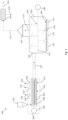
- Fig. 1 illustrates the elements present in a system 100 according to an embodiment of the invention, and the steps included in the corresponding method.
- the system 100 comprises a screw arrangement 200, and a reactor 101.
- the screw arrangement 200 is connected to the reactor 101 via a connecting element 127.
- the screw arrangement 200 is a twin-screw extruder comprising a twin screw 201, inside a drum 208 and driven by a motor 103.
- another type of screw arrangement is possible, for example with a single screw.
- a mass of waste material can be fed into the screw arrangement 200 via an input 102.
- the waste material is, for example, a mixture of plastic waste, in which various types of plastic may be present, for example PE (Polyethylene), PP (Polypropylene), PVC (Polyvinyl chloride), PET (Polyethylene terephthalate), PS (Polystyrene), etc.
- PE Polyethylene
- PP Polypropylene
- PVC Polyvinyl chloride
- PET Polyethylene terephthalate
- PS Polystyrene
- Other examples of waste material are organic waste, food residues, offal, animal feed, rubber, wood, textiles, etc.
- a certain pre-processing of the original mix of waste material can possibly be taking place.
- plastic waste may first undergo a selection, or may be converted to pellets before entering the input 102. Inside the screw arrangement, the supplied mass is advanced, pressurized and heated by turning the screws 201.
- warming takes place purely by mechanical shearing, as a result of friction created by the turning of the screws 201 inside the drum 208.
- the drum wall 208 is heated by means of an external heat source, or wherein the screws 201 are heated.
- the supplied mass of waste material melts.
- the connecting element 127 is a pipe, having a closed wall and two open ends, that connects the exit of the screw arrangement 200 to the reactor 101.
- the pipe 127 is thermally isolated, such that heat loss from the mass towards the environment is limited. Possibly also an external heat source is used, to supply heat towards the pipe, such that the mass in the pipe doesn't cool down and even may be slightly heated up during the transport in the connecting pipe 127.
- mass leaving the screw arrangement is pushed into the connecting pipe 127, such that the mass flows towards the reactor 101.
- a pump may be used to convey the mass towards the reactor 101.
- the reactor 101 is a batch type reactor, comprising a reservoir or container that can be filled to a certain filling level, and where there is no transport of the mass through the reactor.
- the reactor 101 is a horizontal reactor, which can be arranged flat or with a certain inclination relative to the ground level.
- the reactor 101 comprises a cylindrical reservoir, with a reactor wall 104.
- An electrical heater, consisting of several segments 112, is present to heat the reactor wall 104.
- the heating elements 112 are shown in Fig. 1 purely schematically. Heating the reactor wall provides the supply of heat to the mass contained inside the reservoir. This happens in the absence of oxygen, so pyrolysis takes place.
- a mixing arrangement 105 is present in the cylindrical reservoir, which is driven by means of a motor 106.
- the mixing device 105 is a plowshare mixer, schematically represented in Fig. 1 .
- the mixer 105 includes a shaft 125 on which blades 124 are mounted. Driving the shaft 125, via the motor 106, causes the blades 104 to move along the reactor wall 104. When a content is present inside the reservoir, the content is mixed by this movement, and reactor content in the vicinity of the wall 104 is set in motion. In other embodiments, other types of mixing arrangements are possible, or no such mixing arrangement is present.
- One or more input ports 110 are present on the reactor 101, adapted for feeding mass into the reactor 101, as shown schematically in Fig. 1 .
- a discharge port is also present to discharge ashes and any optional catalyst or auxiliary material from the reactor.
- a thermometer and/or pressure meters are present to measure the temperature of the reactor contents or the pressure inside the reactor 101, respectively.
- a scale may also be present to measure the weight of the reactor 101 and thus monitor the amount of waste material to be pyrolyzed inside the reactor.
- the gaseous pyrolysis products 117 which are formed by pyrolysis of the waste material inside the reactor 101, are collected, see 107.
- the system 100 is part of a petrochemical installation.
- Such installation includes the arrangements for further treating and converting the pyrolysis products 117, which are derived from the reactor 101.
- Known technology can be used for this.
- a cooling arrangement 114 is represented schematically, adapted to convert via cooling the condensable hydrocarbons present in the pyrolysis products 117, for example in the range from C5 to C45, into liquid products 115.
- the non-condensable hydrocarbons in the pyrolysis products 117 in the range from C1 to C4, result in gaseous products 116.
- the cooling arrangement 114 may comprise multiple installations, such as different types of heat exchangers, a quench column, etc.
- the screw arrangement 200 includes an input port 111 and 126.
- the input port 111 is used to inject nitrogen, for creating an inert atmosphere inside the extruder 108.
- the input port 126 is used to inject hydrogen into the extruder 108, so as to bind released halogens such as Chlorines and form hydrogen chloride.
- An outlet port 119 is also present on the extruder 108 through which hydrogen chloride vapors can leave the extruder 108.
- an outlet port 118 is also present, through which water vapor that forms inside the extruder 108 can escape during heating. In this way, the drying of the polymer present inside the extruder 108 is promoted.
- a third outlet port 128 is present, through which hydrocarbon vapors, which are formed to a limited extent during residence of the mass in the extruder 200, can be evacuated. Additionally, hydrogen chloride vapors may leave the extruder 200 via the third outlet port 128.
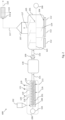
- Fig. 2 shows another embodiment of the system 600.
- the system 600 comprises a buffer tank 130, placed between the screw arrangement 200 and the reactor 101.
- a connecting element 131 for example a pipe, connects the exit of the screw arrangement 200 with the buffer tank 130.
- the mass may be temporarily stored before feeding into the reactor 101.
- the transfer towards the reactor is done by means of a pump 109, via a second connection 132.
- Fig.3 illustrates schematically the different step of the method according to the invention.
- the steps as shown in Fig. 3 are executed by means of a system 100 as presented in Fig. 1 .
- the method may be divided into three successive stages, each time involving a substantial change in the state of the mass to be pyrolyzed.
- a first stage, 503 the mass is transferred through the screw arrangement, see 500. On the one side, during this stage the mass is heated to an exit temperature, thereby being melted. On the other hand, pressure is built up as the mass moves towards the exit of the screw arrangement, up to an exit pressure. This results in reaching an extreme condition 506 at the exit of the screw arrangement.
- This extreme condition is such that during the residence in the screw arrangement 200, an important amount of heat is supplied to the mass, but still substantial pyrolysis in the screw arrangement 200 is avoided, due to the increased pressure. It is possible that during residence in the screw arrangement 200, a limited amount of hydrocarbon vapors is formed. For example, at most 1% of the hydrocarbons present in the supplied waste material, may evaporate during residence in the screw arrangement 200.
- Those gaseous hydrocarbons 129 can be evacuated from the screw arrangement via a third outlet port 128. Possibly, a measurement is present that detects to which extent hydrocarbon vapors 129 are being formed in the screw arrangement 200. During heating in the screw arrangement 200, also water vapor 120 and hydrogen chloride vapors 121 are formed, which leave the screw arrangement via outlet ports 118 and 119 respectively.
- the molten mass is in an unstable, critical condition.
- the mass arrives in the connecting element 127. Because of the high pressure at the exit of the screw arrangement, the mass is being pushed into the connecting pipe 127, thereby causing a flow transport through the pipe 127, see 501.
- an expansion is taken place. During the expansion the pressure decreases from the exit pressure reached at the exit of the screw arrangement 200 to a lower pressure prevailing in the reactor 101. Because of the unstable condition of the mass at the exit of the screw arrangement 200, and the sudden pressure drop in the connecting element 127, pyrolysis of the mass occurs.
- the connecting pipe 127 typically a slight temperature change of the material will occur. This may be a limited cooling, due to heat loss via the wall of the pipe 127, or a limited heating, due to heat supply towards the pipe 127 by means of an external heat source. Typically, the pipe 127 is thermally isolated to avoid heat losses as much as possible. Finally remark that the length of the connecting pipe 127 depends on the type of extruder 200 that is being used. When using a twin-extruder, only having a pumping function to a smaller extent, the length of the connecting pipe 127 needs to be limited, in order to ensure a flow transport up to the reactor 101.
- the design of the installation preferably avoids that the mass needs to be transferred to a higher point, e.g. by using a horizontal connecting pipe 127.
- the extruder 200 with a single screw the extruder is better able to push forward the mass, such that a longer connecting pipe 127 can be used.
- the mass arrives in the reactor 101, where the pyrolysis temperature prevails and the third stage 505 takes place.
- Components being close to degradation when leaving the screw arrangement 200 are quickly transformed into hydrocarbon vapors 117.
- Other components remain some time in the molten condition 502 in the reactor 101, and start to pyrolyze after sufficient heating.
- an arrangement is present at the entry of the reactor 101 to ensure a stable pressure within the reactor 101.
- valves and/or pressure controllers are used to establish a constant reactor pressure, and to ensure that the prevailing conditions in the reactor 101 are not disturbed by what is happening upstream.
- Fig. 3 schematically shows how the process needs to be designed in order to take advantage of the invention.
- the mass is to be brought into an extreme condition by the screw arrangement 200, such that during the subsequent expansion pyrolysis occurs.
- an extreme condition has the advantage that a relatively large portion of the required heat is already absorbed by the mass in the screw arrangement.
- 60 to 70% of the heat that is absorbed by the mass during the process from entry into the screw arrangement to output of the reactor, is absorbed in the screw arrangement.
- the remaining 30 to 40% is then absorbed in the reactor.
- the screw arrangement is maximally deployed, in that part of the warm-up where it can more efficiently realize heat transfer than in a reactor.
- the high fluidity of the material in the reactor and the good contact with the reactor wall there also provides a more efficient heat transfer.
- less energy has to be supplied to the process, for example via the drive of the screw arrangement and the fuel or electrical energy of the reactor heating. This contributes to an improved energy efficiency.
- the necessary residence time in the reactor which is a bottleneck in the process, is reduced, which contributes to an improved time efficiency or capacity.
- a buffer tank 130 like in the embodiment of Fig. 2 , the expansion occurs in the connecting element 131 between the exit of the screw arrangement 200 and the buffer tank 130, with a pressure drop from the exit pressure to a lower pressure in the buffer tank 130. Gaseous hydrocarbons being formed during the expansion are transferred to the buffer tank 130. Possible the buffer tank comprises arrangements to evacuate these gaseous hydrocarbons and to recover them.
- the waste material is a mix of plastic, consisting mainly of PE and PP.
- the mass percentage of PE and PP together in the mix is at least 80%.
- the reactor used for pyrolysis is a reactor 101 as described in Fig. 1 : a batch reactor with horizontally arranged reservoir, without transporting the mass within the reactor, with the presence of a plowshare mixer 105, and use of electric heating 112.
- the mass present in the reactor is continuously mixed by means of the mixer 105.
- the used extruder 108 is a twin-screw extruder with two screws 201 rotating in the same direction.
- a twin-screw extruder having closely meshing screws 201, which allows to create mechanical shear to a large extent.
- Such type of extruder is described, for example, in EP0852533 .
- the engine power is in the order of 2 MW at a propeller speed of 850 rpm.
- the extruder has three injection points through which N2 is injected. Between the extruder and the reactor, there is a pipe, establishing a direct connection between both of them. After the screw arrangement 200, the molten mass is pushed into the connecting pipe 127.
- the extruder 200 is designed and set in such a way that at the exit the mass is at a temperature of 350°C on average.
- the average refers to an average over time as well as to a spatial average over the cross section.
- the mass leaving the extruder 108 is almost completely in a molten state.
- pressure is increased in the mass, up to about 50 bar at the exit of the extruder.
- Vapors comprising released halogens leave the extruder through the outlet port 119. Such vapors arise from about 190°C and dechlorination mainly takes place at a temperature from about 210°C.
- hydrocarbon vapors leave the extruder 200, typically together with additional hydrogen chloride vapors.
- the said hydrocarbon vapors are formed due to limited pyrolysis already taking place in the extruder 200. Extraction of those hydrocarbon vapors from the extruder 200 happens when the mass has a temperature of about 330°C. Depending on the specific mix of material, the mass percentage hydrocarbons already evaporating in the extruder is between 0% and 1%. In the last part of the heating, between 330 °C and 350°C no degassing takes place anymore.
- the pyrolysis is carried out in a semi-continuous process, with the use of the reactor 101 in continuous mode, in a first stage, and use of the reactor 101 in batch mode in a second phase.
- the reactor is used at atmospheric pressure.
- new mass 110 is continuously fed into the reactor 101, while pyrolysis of already present mass in the reactor 101 is in progress.
- the pyrolysis temperature inside the reactor is about 420°C during the continuous mode. Components present in the mass that degrade at the threshold value start degrading shortly after feeding into the reactor 101, that is, carbon-carbon bonds are broken. This produces pyrolysis products 117, which are gaseous at the prevailing temperature, and are collected in the unit 107.
- the energy absorbed by the mass for heating from 20°C to 350°C, with melting is approximately 840 kJ/kg, and the energy absorbed by the mass upon further heating from 350°C to 420°C, to pyrolyzed state, approximately 500 kJ/kg. This means that approximately 63% of the heat to be supplied to the mass in the process is supplied via the screw arrangement 200. The remaining 37% is supplied via the reactor 101.
- the gaseous pyrolysis products 117 leaving the unit 107 are cooled to about 70°C.
- Various types of liquid oils can be formed, such as for example paraffins, isoparaffins, aromatics, fuel similar to diesel, etc.
- the condensate, at a temperature of about 70°C, is collected in a crude oil reservoir, for example.
- the method according to the invention in the first place requires a selection or design of the screw arrangement 200 that is able to establish the intended extreme condition.
- the screw arrangement 200 is controlled by a control unit 113, for example a PLC, regulator or controller.
- the control or setting of the screw arrangement 200 takes place via a signal 123 with which, for example, the speed of the motor 103 is changed, or the set power of the motor 103 is changed, or heating zones on the drum wall 108 are adjusted.
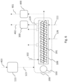
- the control unit 113 in turn receives a signal, which can be interpreted in various ways, see the signal 206, 301 or 403 as illustrated in the embodiments of Figs. 4 , Fig. 5 and Fig. 6 , respectively.
- a computing unit 203 for example a computer, processor or PLC.
- the computing unit 203 receives input 204 which indicates the type of waste material.
- One type of waste material is for example: a mix of PE and PP, a mix of PE, PP and PVC, rubber, etc.
- the mass of waste material can have a heterogeneous composition, in the sense that different types of components are present.
- One type of waste material has an approximately constant composition, averaged over time. For example, the type of waste material is entered via a setting screen.
- the computing unit 203 may further take into account a number of parameter values 205 known beforehand.
- a desired output temperature is determined.
- the desired output temperature is then communicated to the control unit 113, see signal 206.
- the control unit 113 computes how the screw arrangement 200 should be set in order to realize the desired output temperature 206, for example which speed or engine power is optimal, and thus controls the screw arrangement 200, see 123.
- a measuring unit 300 which determines the composition of vapors released from the screw arrangement 200, at a position close to the output.
- the outlet port 128 is used.
- a signal 301 is communicated to the control unit 113, which adjusts the setting of the screw arrangement to avoid further exceeding the threshold value.
- a measuring unit 300 is used, which determines the composition of vapors 129 leaving the screw arrangement 200, analogously to the embodiment of Fig. 5 . It is hereby detected whether or not there are volatile hydrocarbons, see 402.
- a measuring unit 400 present which measures the temperature 401 of mass at the output of the screw arrangement 200.
- the settings of the screw arrangement are gradually adjusted, via communication with the control unit 113, see 403. For example, if the speed is gradually increased, and hydrocarbons are detected from a certain speed, then the targeted extreme condition is reached.
- Such an experimental setup can be performed once, if, for example, the same type of waste material continues to be used. After the experimental determination of the extreme condition, the screw arrangement is then set once, and the setting is not changed anymore during the operational process.
Landscapes
- Chemical & Material Sciences (AREA)
- Engineering & Computer Science (AREA)
- Oil, Petroleum & Natural Gas (AREA)
- Materials Engineering (AREA)
- Organic Chemistry (AREA)
- Combustion & Propulsion (AREA)
- Mechanical Engineering (AREA)
- Separation, Recovery Or Treatment Of Waste Materials Containing Plastics (AREA)
- Production Of Liquid Hydrocarbon Mixture For Refining Petroleum (AREA)
Claims (13)
- Verfahren zur Pyrolyse einer Masse an Abfallstoffen, umfassend:- Bereitstellen einer Schneckenanordnung (200), die dazu geeignet ist, der Masse durch mechanisches Scheren Wärme zuzuführen;- Bereitstellen eines Verbindungselements (127), das mit dem Austritt der Schneckenanordnung (200) verbunden ist;- Bereitstellen eines Reaktors (101) nach dem Verbindungselement (127), der dazu geeignet ist, der Masse in Abwesenheit von Sauerstoff Wärme zuzuführen, indem die Reaktorwand (104) mit einer externen Wärmequelle (112) erwärmt wird;- Fördern der Masse durch die Schneckenanordnung (200) in Richtung des Austritts der Schneckenanordnung (200), während die Masse zumindest durch mechanisches Scheren erwärmt wird und während der Druck der Masse erhöht wird, so dass die Masse am Austritt der Schneckenanordnung (200) geschmolzen ist und die Masse in einen Austrittszustand mit einer Austrittstemperatur und einem Austrittsdruck gebracht ist;- Ausdehnen der Masse in dem Verbindungselement (127) mit einem Druckabfall von dem Austrittsdruck auf einen niedrigeren Druck;- Transportieren der Masse durch das Verbindungselement (127) in Richtung des Reaktors;- thermisches Abbauen der Masse in dem Reaktor (101), wobei Kohlenstoff-Kohlenstoff-Bindungen in der Masse durch Pyrolyse aufgebrochen werden und flüchtige Kohlenwasserstoffe gebildet werden,DADURCH GEKENNZEICHNET, DASS:- der Reaktor (101) einen Behälter und eine Mischanordnung (105) umfasst, wobei der Reaktor (101) zur Pyrolyse einer Masse geeignet ist, die den Behälter bis zu einem gewissen Füllstand füllt, ohne die Masse durch den Reaktor zu transportieren, wobei eine Bewegung der Masse relativ zu der Reaktorwand (104) aus dem Mischen innerhalb des Behälters resultiert, wobei der Reaktor (101) während des thermischen Abbaus im kontinuierlichen Modus, im Batch-Modus oder abwechselnd im kontinuierlichen und im Batch-Modus betrieben wird, wobei im kontinuierlichen Modus während des thermischen Abbaus kontinuierlich Masse in den Behälter gespeist wird und im Batch-Modus während des thermischen Abbaus keine Masse in den Behälter gespeist wird;- die Austrittsbedingung einer Extrembedingung entspricht,wobei die Extrembedingung derart ist, dass:- ein Anteil der Masse während des Verweilens der Masse in der Schneckenanordnung (200) in gasförmige Kohlenwasserstoffe (129) umgewandelt wird, wobei der Anteil höchstens 1 % Masseprozente der in der Masse am Eintritt der Schneckenanordnung (200) vorhandenen Kohlenwasserstoffe beträgt, und- während des Druckabfalls in dem Verbindungselement (127) eine Pyrolyse erfolgt, wodurch gasförmige Kohlenwasserstoffe innerhalb des Verbindungselements (127) gebildet werden;und wobei das Verfahren ferner Folgendes umfasst:- Abführen von gasförmigen Kohlenwasserstoffen (129), die während des Verweilens in der Schneckenanordnung (200) gebildet werden, aus der Masse über eine oder mehrere Auslassöffnungen (128) an der Schneckenanordnung (200);- Fördern von während des Druckabfalls gebildeten gasförmigen Kohlenwasserstoffen zusammen mit der geschmolzenen Masse, wobei die während des Druckabfalls gebildeten gasförmigen Kohlenwasserstoffe beim Strömen in dem Verbindungselement (127) durch die Masse mitgeführt werden.
- Verfahren nach einem der vorhergehenden Ansprüche,
wobei das Verfahren Folgendes umfasst:- Abführen von Wasserdampf (120), der während des Erhitzens in der Schneckenanordnung (200) aus der Masse freigesetzt wird, über eine erste Auslassöffnung (118) an der Schneckenanordnung (200);- Abführen von Halogen umfassenden Gasen (120), die während des Erhitzens in der Schneckenanordnung (200) aus der Masse freigesetzt werden, über eine zweite Auslassöffnung (119) an der Schneckenanordnung (200);- Abführen von gasförmigen Kohlenwasserstoffen (129), die während des Erhitzens in der Schneckenanordnung (200) aus der Masse freigesetzt werden, über eine dritte Auslassöffnung (128) an der Schneckenanordnung (200). - Verfahren nach einem der vorhergehenden Ansprüche,wobei das Verbindungselement (127) eine direkte Verbindung zwischen der Schneckenanordnung (200) und dem Reaktor (101) bereitstellt und der Druckabfall von dem Austrittsdruck auf einen Reaktordruck, der niedriger als der Austrittsdruck ist, erfolgt,oder das Verbindungselement (131) eine Verbindung zwischen der Schneckenanordnung (200) und einem Puffertank (130) bereitstellt, der zwischen der Schneckenanordnung (200) und dem Reaktor (101) platziert ist, und der Druckabfall von dem Austrittsdruck auf einen Druck in dem Puffertank (130), der niedriger als der Austrittsdruck ist, erfolgt.
- Verfahren nach Anspruch 3,
wobei das Verfahren Folgendes umfasst:
Transportieren der Masse durch das Verbindungselement (127, 131), wobei die während des Druckabfalls gebildeten gasförmigen Kohlenwasserstoffe durch die Masse mitgeführt werden, die in Richtung des Reaktors (101) oder des Puffertanks (131) strömt. - Verfahren nach einem der vorhergehenden Ansprüche,
wobei die während des Druckabfalls in dem Verbindungselement (127) gebildeten gasförmigen Kohlenwasserstoffe als in der geschmolzenen Masse vorhandene Gasblasen auftreten. - Verfahren nach einem der vorhergehenden Ansprüche,
wobei der Druckunterschied zwischen dem Austrittsdruck und dem niedrigeren Druck ein Strömen der Masse bewirkt, wodurch die Masse durch das Verbindungselement (127) transportiert wird. - Verfahren nach einem der vorhergehenden Ansprüche,
wobei die Abfallstoffe zu mindestens 80 % ihrer Massenprozente aus Polyethylen und/oder Polypropylen bestehen und die Ausgangstemperatur höher als 330 °C ist, vorzugsweise zwischen 340 °C und 380 °C. - Verfahren nach einem der vorhergehenden Ansprüche,
wobei der Reaktor (101) einen Behälter umfasst, der dazu geeignet ist, bis zu einem Füllstand mit der Masse gefüllt zu werden, wobei innerhalb des Behälters- eine Mischanordnung (105) vorhanden ist, die zum Mischen der Masse innerhalb des Behälters geeignet ist;- keine Anordnung zum Transportieren der Masse durch den Behälter vorhanden ist. - Verfahren nach Anspruch 8,
wobei der Reaktor (101) abwechselnd im kontinuierlichen Modus und im Batch-Modus betrieben wird, wobei- im kontinuierlichen Modus während des thermischen Abbaus kontinuierlich Masse in den Reaktor (101) gespeist wird und- im Batch-Modus während des thermischen Abbaus keine Masse in den Reaktor (101) gespeist wird. - Verfahren nach einem der vorhergehenden Ansprüche,
wobei während des thermischen Abbaus die Reaktorwand (104) so erhitzt wird, dass innerhalb des Reaktors (101) eine Pyrolysetemperatur herrscht, die höher als die Austrittstemperatur ist, vorzugsweise 50 °C bis 150 °C höher als die Austrittstemperatur, und wobei die Pyrolysetemperatur in dem Reaktor (101) während des Batch-Modus höher ist als während des kontinuierlichen Modus, vorzugsweise 60 °C bis 100 °C höher. - Verfahren nach einem der vorhergehenden Ansprüche,
wobei- die Schneckenanordnung (200) drei verschiedene Auslassöffnungen (118, 119, 128) umfasst, die dazu geeignet sind, Wasserdampf, Halogen umfassende Gase und gasförmige Kohlenwasserstoffe aus der Schneckenanordnung (200) abzuführen;- das Verbindungselement (127) eine geschlossene Wand umfasst und zum Transportieren der Masse, die gasförmige Kohlenwasserstoffe umfasst, die während der Ausdehnung gebildet werden, geeignet ist, indem es ermöglicht, dass die Masse in Gegenwart des Austrittsdrucks durch das Verbindungselement strömt. - Verfahren nach Anspruch 11,
wobei das Verbindungselement (127) ein oder mehrere Rohre umfasst, und wobei die innere Oberfläche des einen oder der mehreren Rohre mit einer Beschichtung mit Antihafteigenschaften versehen ist, wobei die Beschichtung dazu geeignet ist, ein Anhaften der Masse an der inneren Oberfläche zu verringern. - Verfahren nach einem der vorhergehenden Ansprüche,
wobei das System (100) eine Messung (300) umfasst, die dazu geeignet ist, eine Freisetzung gasförmiger Kohlenwasserstoffe aus der Masse in der Schneckenanordnung (200) zu erkennen.
Applications Claiming Priority (2)
| Application Number | Priority Date | Filing Date | Title |
|---|---|---|---|
| BE20205538A BE1028485B1 (nl) | 2020-07-17 | 2020-07-17 | Methode voor pyrolyse van afvalmateriaal in industrieel proces |
| PCT/IB2021/056251 WO2022013712A1 (en) | 2020-07-17 | 2021-07-12 | Method for pyrolysis of waste material in an industrial process |
Publications (3)
| Publication Number | Publication Date |
|---|---|
| EP4182405A1 EP4182405A1 (de) | 2023-05-24 |
| EP4182405C0 EP4182405C0 (de) | 2024-09-11 |
| EP4182405B1 true EP4182405B1 (de) | 2024-09-11 |
Family
ID=71833086
Family Applications (1)
| Application Number | Title | Priority Date | Filing Date |
|---|---|---|---|
| EP21740617.2A Active EP4182405B1 (de) | 2020-07-17 | 2021-07-12 | Verfahren zur pyrolyse von abfallstoffen in einem industriellen verfahren |
Country Status (6)
| Country | Link |
|---|---|
| US (1) | US12338393B2 (de) |
| EP (1) | EP4182405B1 (de) |
| BE (2) | BE1028485B1 (de) |
| CA (1) | CA3184984A1 (de) |
| NL (1) | NL2028704B1 (de) |
| WO (1) | WO2022013712A1 (de) |
Families Citing this family (5)
| Publication number | Priority date | Publication date | Assignee | Title |
|---|---|---|---|---|
| BE1028485B1 (nl) | 2020-07-17 | 2022-02-15 | Cct Int | Methode voor pyrolyse van afvalmateriaal in industrieel proces |
| JP2025508756A (ja) * | 2022-02-18 | 2025-04-10 | ブライトマーク・プラスティックス・レニューアル・テクノロジーズ・エルエルシー | 熱分解したプラスチック廃棄物原料から化学化合物および/またはガスを生成するためのバッチシステム |
| KR20250010039A (ko) | 2022-05-10 | 2025-01-20 | 메이킨 퍼스트 | 잔류 플라스틱 생성물로부터 탄화수소 화합물의 생산을 위한 열분해 시스템 |
| EP4556545A1 (de) | 2023-11-14 | 2025-05-21 | Makeen Energy A/S | Kohlenwasserstoff-verbundmischung mit verbesserten eigenschaften aus kunststoffabfällen |
| US20250320409A1 (en) | 2024-01-29 | 2025-10-16 | Nexus Circular LLC | Systems and methods for making hydrocarbon compositions derived from pyrolysis of post-consumer and/or post-industrial plastics |
Citations (1)
| Publication number | Priority date | Publication date | Assignee | Title |
|---|---|---|---|---|
| WO2020070343A1 (es) * | 2018-10-02 | 2020-04-09 | Evoluciones Tecnológicas Madrileñas, S. L. | Procedimiento de pirólisis con descompresión rápida |
Family Cites Families (20)
| Publication number | Priority date | Publication date | Assignee | Title |
|---|---|---|---|---|
| US3947256A (en) * | 1971-05-10 | 1976-03-30 | Kabushiki Kaisha Niigata Tekrosho | Method for decomposition of polymers into fuels |
| US5608136A (en) * | 1991-12-20 | 1997-03-04 | Kabushiki Kaisha Toshiba | Method and apparatus for pyrolytically decomposing waste plastic |
| US5686055A (en) * | 1993-12-27 | 1997-11-11 | Mazda Motor Corporation | Process for recovering phthalic anhydride and hydrogen chloride from plastic materials |
| DE19536289C2 (de) | 1995-09-29 | 1999-01-07 | Krupp Werner & Pfleiderer Gmbh | Verfahren zur Durchführung von kontinuierlichen Aufbereitungsprozessen mit gleichsinnig drehenden, dicht kämmenden Doppelschneckenextrudern |
| ES2130040B1 (es) * | 1996-04-29 | 1999-12-01 | Olmos Ibanez Desamparados | Procedimiento para la recuperacion de aluminio y energia a partir de envases usados tipo "tetrabrick" y horno para realizarlo. |
| US6048380A (en) * | 1996-06-11 | 2000-04-11 | Nkk Corporation | Method for disposing synthetic resinous material |
| US6534689B1 (en) * | 2001-08-24 | 2003-03-18 | Pyrocat Ltd. | Process for the conversion of waste plastics to produce hydrocarbon oils |
| JP4210222B2 (ja) * | 2004-01-15 | 2009-01-14 | 乕 吉村 | 廃プラスチックの油化還元装置 |
| US7144558B2 (en) * | 2004-07-01 | 2006-12-05 | Biogas Technologies, Inc. | Wood gasification apparatus |
| US8187428B2 (en) * | 2006-05-25 | 2012-05-29 | Blest Co., Ltd. | Liquefying apparatus |
| US7893307B2 (en) | 2007-02-23 | 2011-02-22 | Smith David G | Apparatus and process for converting feed material into reusable hydrocarbons |
| DE102008029305A1 (de) | 2008-06-20 | 2009-12-24 | Bayer Technology Services Gmbh | Schneckenelemente mit reduziertem Kammwinkel |
| MY152962A (en) * | 2008-08-20 | 2014-12-15 | Fuel Ltd P | Disposal of electrical and electronic equipment |
| WO2011009074A2 (en) * | 2009-07-16 | 2011-01-20 | Champagne Gary E | Vacuum pyrolytic gasification and liquefaction to produce liquid and gaseous fuels from biomass |
| US20120266529A1 (en) * | 2011-04-22 | 2012-10-25 | John Scahill | Fast pyrolysis system |
| ES2938584T3 (es) | 2012-02-15 | 2023-04-12 | Neste Oyj | Aparato de pirólisis delineado por zonas, de etapa dual |
| IL263806B (en) * | 2016-06-21 | 2022-09-01 | Braven Env Llc | System and method for coal separation |
| MX2018015964A (es) * | 2016-07-05 | 2019-05-16 | Golden Renewable Energy Llc | Sistema y proceso para convertir plastico de desecho en combustible. |
| GB2590061B (en) * | 2019-11-04 | 2022-05-11 | Recycling Tech Ltd | Improvements in and relating to reactor feed systems |
| BE1028485B1 (nl) | 2020-07-17 | 2022-02-15 | Cct Int | Methode voor pyrolyse van afvalmateriaal in industrieel proces |
-
2020
- 2020-07-17 BE BE20205538A patent/BE1028485B1/nl active IP Right Grant
-
2021
- 2021-07-12 EP EP21740617.2A patent/EP4182405B1/de active Active
- 2021-07-12 CA CA3184984A patent/CA3184984A1/en active Pending
- 2021-07-12 WO PCT/IB2021/056251 patent/WO2022013712A1/en not_active Ceased
- 2021-07-12 NL NL2028704A patent/NL2028704B1/nl active
- 2021-07-12 US US18/016,296 patent/US12338393B2/en active Active
- 2021-07-12 BE BE20215543A patent/BE1028424B1/nl active IP Right Grant
Patent Citations (2)
| Publication number | Priority date | Publication date | Assignee | Title |
|---|---|---|---|---|
| WO2020070343A1 (es) * | 2018-10-02 | 2020-04-09 | Evoluciones Tecnológicas Madrileñas, S. L. | Procedimiento de pirólisis con descompresión rápida |
| EP3862410A1 (de) * | 2018-10-02 | 2021-08-11 | Evoluciones Tecnológicas Madrileñas, S. L. | Pyrolyseverfahren mit schneller dekompression |
Also Published As
| Publication number | Publication date |
|---|---|
| EP4182405C0 (de) | 2024-09-11 |
| US12338393B2 (en) | 2025-06-24 |
| BE1028424B1 (nl) | 2022-10-27 |
| CA3184984A1 (en) | 2022-01-20 |
| WO2022013712A1 (en) | 2022-01-20 |
| EP4182405A1 (de) | 2023-05-24 |
| NL2028704B1 (nl) | 2022-07-22 |
| NL2028704A (nl) | 2022-04-29 |
| BE1028485B1 (nl) | 2022-02-15 |
| US20230265348A1 (en) | 2023-08-24 |
| BE1028485A1 (nl) | 2022-02-08 |
| BE1028424A1 (nl) | 2022-01-25 |
Similar Documents
| Publication | Publication Date | Title |
|---|---|---|
| EP4182405B1 (de) | Verfahren zur pyrolyse von abfallstoffen in einem industriellen verfahren | |
| US12018213B2 (en) | Reactor feed systems | |
| KR101298819B1 (ko) | 무수 무용매 중합체의 제조 방법 | |
| JP2024503111A (ja) | 廃プラスチックの石油化学製品への変換 | |
| CN116018203B (zh) | 塑料转换进料系统 | |
| WO2013171510A1 (en) | Processing waste polymeric material | |
| JP2023507514A (ja) | プラスチック材料を熱分解するための方法およびそのシステム | |
| KR20240044482A (ko) | 수명 만료 플라스틱의 열분해를 위한 시스템 및 장치 | |
| JP2023548389A (ja) | 廃棄プラスチック材料を有用な生成物に変換するためのシステム及び方法、並びに固形物圧縮ユニット | |
| WO2017220409A1 (en) | Removal of char in a process for conversion of waste hydrocarbon material into fuel | |
| EP3347436A2 (de) | Flash-pyrolysereaktor | |
| NL1009664C2 (nl) | Werkwijze voor gefaseerde warmtebehandeling en inrichting voor het uitvoeren van die werkwijze. | |
| KR100808123B1 (ko) | 누벽식 열분해 반응기 | |
| JP3321640B2 (ja) | 熱分解装置および熱分解方法 | |
| CN121843801A (zh) | 用于处理塑料废物的方法 | |
| CN115305103A (zh) | 一种增强有机固废热裂解过程中表观传热系数的反应装置 | |
| CH720107A2 (fr) | Dispositif de réaction pour améliorer le coefficient de transfert de chaleur apparent dans le processus de pyrolyse de déchets solides organiques. | |
| WO2025037405A1 (ja) | 脱塩ユニット及び脱塩方法 | |
| CA3256225A1 (en) | A method for pyrolysing plastic material and a system therefor | |
| JP2025169674A (ja) | 樹脂成形体の製造方法および製造設備 | |
| WO2024232366A1 (ja) | 廃プラスチックの油化システム及び熱分解炉の出口部分の配管 | |
| NO20240711A1 (de) | ||
| BE884302A (fr) | Procede et appareil de production d'une masse de caoutchouc fondue |
Legal Events
| Date | Code | Title | Description |
|---|---|---|---|
| STAA | Information on the status of an ep patent application or granted ep patent |
Free format text: STATUS: UNKNOWN |
|
| STAA | Information on the status of an ep patent application or granted ep patent |
Free format text: STATUS: THE INTERNATIONAL PUBLICATION HAS BEEN MADE |
|
| PUAI | Public reference made under article 153(3) epc to a published international application that has entered the european phase |
Free format text: ORIGINAL CODE: 0009012 |
|
| STAA | Information on the status of an ep patent application or granted ep patent |
Free format text: STATUS: REQUEST FOR EXAMINATION WAS MADE |
|
| 17P | Request for examination filed |
Effective date: 20230217 |
|
| AK | Designated contracting states |
Kind code of ref document: A1 Designated state(s): AL AT BE BG CH CY CZ DE DK EE ES FI FR GB GR HR HU IE IS IT LI LT LU LV MC MK MT NL NO PL PT RO RS SE SI SK SM TR |
|
| DAV | Request for validation of the european patent (deleted) | ||
| DAX | Request for extension of the european patent (deleted) | ||
| GRAP | Despatch of communication of intention to grant a patent |
Free format text: ORIGINAL CODE: EPIDOSNIGR1 |
|
| STAA | Information on the status of an ep patent application or granted ep patent |
Free format text: STATUS: GRANT OF PATENT IS INTENDED |
|
| INTG | Intention to grant announced |
Effective date: 20240415 |
|
| GRAS | Grant fee paid |
Free format text: ORIGINAL CODE: EPIDOSNIGR3 |
|
| GRAA | (expected) grant |
Free format text: ORIGINAL CODE: 0009210 |
|
| STAA | Information on the status of an ep patent application or granted ep patent |
Free format text: STATUS: THE PATENT HAS BEEN GRANTED |
|
| RAP3 | Party data changed (applicant data changed or rights of an application transferred) |
Owner name: CCT INTERNATIONAL |
|
| AK | Designated contracting states |
Kind code of ref document: B1 Designated state(s): AL AT BE BG CH CY CZ DE DK EE ES FI FR GB GR HR HU IE IS IT LI LT LU LV MC MK MT NL NO PL PT RO RS SE SI SK SM TR |
|
| REG | Reference to a national code |
Ref country code: GB Ref legal event code: FG4D |
|
| REG | Reference to a national code |
Ref country code: CH Ref legal event code: EP |
|
| REG | Reference to a national code |
Ref country code: DE Ref legal event code: R096 Ref document number: 602021018692 Country of ref document: DE |
|
| REG | Reference to a national code |
Ref country code: IE Ref legal event code: FG4D |
|
| U01 | Request for unitary effect filed |
Effective date: 20240917 |
|
| U07 | Unitary effect registered |
Designated state(s): AT BE BG DE DK EE FI FR IT LT LU LV MT NL PT RO SE SI Effective date: 20241009 |
|
| PG25 | Lapsed in a contracting state [announced via postgrant information from national office to epo] |
Ref country code: NO Free format text: LAPSE BECAUSE OF FAILURE TO SUBMIT A TRANSLATION OF THE DESCRIPTION OR TO PAY THE FEE WITHIN THE PRESCRIBED TIME-LIMIT Effective date: 20241211 |
|
| PG25 | Lapsed in a contracting state [announced via postgrant information from national office to epo] |
Ref country code: GR Free format text: LAPSE BECAUSE OF FAILURE TO SUBMIT A TRANSLATION OF THE DESCRIPTION OR TO PAY THE FEE WITHIN THE PRESCRIBED TIME-LIMIT Effective date: 20241212 |
|
| PG25 | Lapsed in a contracting state [announced via postgrant information from national office to epo] |
Ref country code: HR Free format text: LAPSE BECAUSE OF FAILURE TO SUBMIT A TRANSLATION OF THE DESCRIPTION OR TO PAY THE FEE WITHIN THE PRESCRIBED TIME-LIMIT Effective date: 20240911 |
|
| PG25 | Lapsed in a contracting state [announced via postgrant information from national office to epo] |
Ref country code: ES Free format text: LAPSE BECAUSE OF FAILURE TO SUBMIT A TRANSLATION OF THE DESCRIPTION OR TO PAY THE FEE WITHIN THE PRESCRIBED TIME-LIMIT Effective date: 20240911 |
|
| PG25 | Lapsed in a contracting state [announced via postgrant information from national office to epo] |
Ref country code: NO Free format text: LAPSE BECAUSE OF FAILURE TO SUBMIT A TRANSLATION OF THE DESCRIPTION OR TO PAY THE FEE WITHIN THE PRESCRIBED TIME-LIMIT Effective date: 20241211 Ref country code: HR Free format text: LAPSE BECAUSE OF FAILURE TO SUBMIT A TRANSLATION OF THE DESCRIPTION OR TO PAY THE FEE WITHIN THE PRESCRIBED TIME-LIMIT Effective date: 20240911 Ref country code: GR Free format text: LAPSE BECAUSE OF FAILURE TO SUBMIT A TRANSLATION OF THE DESCRIPTION OR TO PAY THE FEE WITHIN THE PRESCRIBED TIME-LIMIT Effective date: 20241212 Ref country code: ES Free format text: LAPSE BECAUSE OF FAILURE TO SUBMIT A TRANSLATION OF THE DESCRIPTION OR TO PAY THE FEE WITHIN THE PRESCRIBED TIME-LIMIT Effective date: 20240911 |
|
| PG25 | Lapsed in a contracting state [announced via postgrant information from national office to epo] |
Ref country code: IS Free format text: LAPSE BECAUSE OF FAILURE TO SUBMIT A TRANSLATION OF THE DESCRIPTION OR TO PAY THE FEE WITHIN THE PRESCRIBED TIME-LIMIT Effective date: 20250111 |
|
| PG25 | Lapsed in a contracting state [announced via postgrant information from national office to epo] |
Ref country code: SM Free format text: LAPSE BECAUSE OF FAILURE TO SUBMIT A TRANSLATION OF THE DESCRIPTION OR TO PAY THE FEE WITHIN THE PRESCRIBED TIME-LIMIT Effective date: 20240911 |
|
| PG25 | Lapsed in a contracting state [announced via postgrant information from national office to epo] |
Ref country code: CZ Free format text: LAPSE BECAUSE OF FAILURE TO SUBMIT A TRANSLATION OF THE DESCRIPTION OR TO PAY THE FEE WITHIN THE PRESCRIBED TIME-LIMIT Effective date: 20240911 Ref country code: PL Free format text: LAPSE BECAUSE OF FAILURE TO SUBMIT A TRANSLATION OF THE DESCRIPTION OR TO PAY THE FEE WITHIN THE PRESCRIBED TIME-LIMIT Effective date: 20240911 |
|
| PG25 | Lapsed in a contracting state [announced via postgrant information from national office to epo] |
Ref country code: SK Free format text: LAPSE BECAUSE OF FAILURE TO SUBMIT A TRANSLATION OF THE DESCRIPTION OR TO PAY THE FEE WITHIN THE PRESCRIBED TIME-LIMIT Effective date: 20240911 |
|
| PLBE | No opposition filed within time limit |
Free format text: ORIGINAL CODE: 0009261 |
|
| STAA | Information on the status of an ep patent application or granted ep patent |
Free format text: STATUS: NO OPPOSITION FILED WITHIN TIME LIMIT |
|
| 26N | No opposition filed |
Effective date: 20250612 |
|
| U20 | Renewal fee for the european patent with unitary effect paid |
Year of fee payment: 5 Effective date: 20250731 |
|
| PGFP | Annual fee paid to national office [announced via postgrant information from national office to epo] |
Ref country code: GB Payment date: 20250722 Year of fee payment: 5 |
|
| REG | Reference to a national code |
Ref country code: CH Ref legal event code: H13 Free format text: ST27 STATUS EVENT CODE: U-0-0-H10-H13 (AS PROVIDED BY THE NATIONAL OFFICE) Effective date: 20260224 |